EP2500708B1 - Anordnung und Verfahren zur Baugruppenprüfung, insbesondere zur Achsdämpfungsprüfung, in Fahrzeugen - Google Patents
Anordnung und Verfahren zur Baugruppenprüfung, insbesondere zur Achsdämpfungsprüfung, in Fahrzeugen Download PDFInfo
- Publication number
- EP2500708B1 EP2500708B1 EP12158992.3A EP12158992A EP2500708B1 EP 2500708 B1 EP2500708 B1 EP 2500708B1 EP 12158992 A EP12158992 A EP 12158992A EP 2500708 B1 EP2500708 B1 EP 2500708B1
- Authority
- EP
- European Patent Office
- Prior art keywords
- vehicle
- adapter
- measurement data
- acceleration
- measuring
- Prior art date
- Legal status (The legal status is an assumption and is not a legal conclusion. Google has not performed a legal analysis and makes no representation as to the accuracy of the status listed.)
- Active
Links
Images

Classifications
-
- G—PHYSICS
- G01—MEASURING; TESTING
- G01M—TESTING STATIC OR DYNAMIC BALANCE OF MACHINES OR STRUCTURES; TESTING OF STRUCTURES OR APPARATUS, NOT OTHERWISE PROVIDED FOR
- G01M17/00—Testing of vehicles
- G01M17/007—Wheeled or endless-tracked vehicles
- G01M17/04—Suspension or damping
Definitions
- the invention relates to a method for component testing, in which a vibration of a vehicle is excited and measurement data are generated by measuring the acceleration, deceleration or vibration behavior by means of at least one sensor which is introduced into the vehicle and / or is connected to the vehicle.
- the invention also relates to an arrangement for carrying out the method with an excitation means for exciting a vibration of a vehicle and a measuring means for measuring the acceleration, deceleration or vibration behavior by means of sensors incorporated into the vehicle and / or connected to the vehicle.
- test data are recorded from a vehicle of the same type as the vehicle under test under real driving conditions and then passed on to the test vehicle on the bus via which the components are connected to one another.
- This is always a diagnosis of one and the same vehicle type, the bus protocol and the interface configurations, including the configuration of the vehicle diagnosis interface, are known and remain unchanged.
- DE 10258265 A1 relates to a method for monitoring spring-damper systems in which the vibration behavior of the spring-damper unit is sensed while driving and from the vibration behavior a malfunction of the spring-damper unit (s), such as a defect, a malfunction or a deviation of the properties from the Normal range, etc. is determined, and in which the decay behavior of an oscillation curve and / or its oscillation frequency is observed as a result of an, in particular time-limited, mechanical excitation of the spring damper units in order to identify the malfunction.
- s such as a defect, a malfunction or a deviation of the properties from the Normal range, etc.
- EP 0997720 A2 relates to a method for brake testing by means of deceleration measurement of motor vehicles, in which the vehicle is braked to a standstill from a specific movement.
- the linear deceleration of the vehicle is measured and registered as a function of time using a linear accelerator in the direction of the longitudinal axis of the vehicle, and the lateral acceleration is measured and recorded, and the relevant associated braking forces are determined therefrom, with the braking as full braking from a specific one Speed out to a standstill and without intervention on the steering wheel and the accelerometers are rigidly connected to the vehicle for testing purposes.
- the vehicle's nodding towards the brake pad is determined and evaluated to evaluate the quality of the wheel suspension, in particular the shock absorber.
- US 2002/0111718 A1 describes a method for predicting the sound and vibration levels inside a vehicle traveling on a floor with one or more obstacles or on a floor with a given grain size.
- the vehicle travels at a given speed V on a floor which is provided with at least one obstacle of a predetermined size.
- the method has a first step of determining a global transfer function of the vehicle equipped with a reference connection system with the ground, and a second step in which forces are measured at the connection points of the prototype connection system to the floor with the structure.
- a global transfer function characteristic of the vehicle is calculated for each speed around the speed V, which is derived from a first transfer function , which makes it possible to determine the sound pressure in the vehicle interior, taking into account the forces at the connection points with the body, and there is a second transfer function, which, taking into account the same forces at the connection points with the body, enables the vibration levels on the steering wheel and on the floor of the vehicle.
- the difference between a first physical quantity and a second physical quantity, each of which affects a human body, in particular in its sitting position, is a measure of the driving comfort of a person in a vehicle.
- the first physical quantity is formed by a vibration that acts directly on the human body and the second physical quantity by a difference in the time delay of a vibration in all directions that is added to the human body.
- vehicle should be understood to mean any type of vehicle, such as generally motor vehicles or commercial vehicles, motorcycles, motor vehicle trailers, etc., and the combinations thereof.
- a vehicle is excited to vibrate.
- the acceleration, deceleration or vibration behavior is measured by means of at least one sensor that is introduced into the vehicle and / or connected to the vehicle.
- This measurement data is evaluated using a learning-based classification algorithm.
- This serves to classify the functionality of axle dampers in terms of usability.
- a training set of measurement data is created by measuring the acceleration, deceleration or vibration behavior in a defined measurement environment for a vehicle and / or a vehicle type.
- the classification algorithm is trained using the training set of measurement data and on the basis of known axle damping parameters. Once the training of the classification algorithm has been completed, measured values are evaluated in the current axle damping measurement process using the classification algorithm.
- the classification result is in the form of a dichotomous decision about the functional state of the axle damper and / or a degree of degradation of the functionality of the Axle damper issued.
- the classification can also be done with a provided, already trained classification algorithm.
- the training set it is also possible for the training set to be expanded with classified measurement data from a current measurement.
- the training of the classification algorithm for the classification of subsequent measurement data is then carried out using this extended training set.
- initial measurements are used for training, but also the current measurements themselves.
- Another aspect of the invention relates to vibration excitation. This can be done by a single stimulus from an obstacle such as a threshold, a pothole or a ramp. When driving over the obstacle, the axes are excited to vibrate once and the course of the vibration is recorded by means of an acceleration and / or rotation rate sensor. Furthermore, the vibration can be excited periodically. Several similar obstacles, which follow each other at certain intervals, are run over. Here, a statement is made about the level of the vibration amplitude at the resonance frequency. This in turn allows conclusions to be drawn about the damping of the system. In addition, the vibration can be excited when braking, in particular by combining the dynamic brake test and damping test. Here, the vehicle is braked sharply, causing the vehicle to nod.
- the vehicle When the vehicle has come to a standstill, the vehicle changes from the dozed position to the idle state. This transition follows a damped oscillation.
- the vibration excitation can also be stochastic during normal driving. Here, the inspector drives over an undefined route over an undefined time. The course of the vibration is recorded and evaluated. A suitable method is used to make a statement about the quality of the system's dampers.
- the measurement results can preferably be classified by comparison with known error-free measurement result patterns.
- One aspect of the invention relates to the evaluation of the measurement data in the form of an evaluation of the vibration behavior. This is preferably done in the direction of gravitational acceleration and in the transverse direction, using individual vibration parameters such as decay constant, degree of damping, period of oscillation, frequency.
- the vibration behavior is measured in the time domain.
- the classification can, however, take place after a transformation in the frequency domain.
- Another aspect of the invention relates to the alignment of the sensor. These are carried out numerically on the basis of measuring the acceleration due to gravity when stationary and the acceleration during a change in speed, preferably by means of a coordinate transformation.
- the gravitational acceleration vector is determined by averaging the acceleration values, which are shown in the coordinate system of the SKS sensor.
- the angle between this vector and the unit vector in the direction of the Z axis and the normal vector (axis of rotation) to the plane which these two vectors span are determined.
- a first rotation matrix is calculated from this and a second coordinate system SKS * is created.
- the vehicle acceleration vector is determined by averaging the X and Y values shown in the second coordinate system SKS * and determining the angle between the vector of the mean values and the unit vector in the direction of the X axis. With the angle and the axis of rotation that now corresponds to the unit vector in the direction of the Z axis, a second rotation matrix can be calculated with which the second coordinate system SKS * can be converted into the vehicle coordinate system FKS.
- the two rotation matrices can be combined by means of matrix multiplication, and the raw acceleration and rotation rate data from the SKS coordinate system can now be mapped directly in the vehicle coordinate system FKS using the resulting matrix.
- One aspect of the invention relates to the evaluation of the measured values obtained by means of the sensor. These are analyzed in combination with further measurement values obtained by means of further sensors, preferably the brake pressure, preferably with regard to the plausibility of the measurement results obtained.
- One embodiment of the invention provides that the measured values are stored.
- the measured values may be transmitted from the adapter to an evaluation unit via an interface.
- Another aspect of the invention relates to vibration excitation.
- the resulting vibration is based on avoidable errors such as skewed opening and / or incorrect calibration and / or an unsuitable, e.g. a too high or too low, speed checked.
- the arrangement-based solution of the task consists in a device which excitation means for exciting a vibration of a vehicle, measuring means for measuring the Has acceleration, deceleration or vibration behavior by means of sensors and evaluation means, which are introduced into the vehicle and / or connected to the vehicle, for evaluating the measurement data by means of the learning-based classification algorithm described in the method.
- an adapter that can be inserted into a vehicle or that can be connected to the vehicle is provided with a 3-axis acceleration and / or a 3-axis rotation rate sensor that is connected to means for recording measured values.
- an acceleration sensor preferably a 3-D acceleration sensor and / or a rotation rate sensor, preferably a 3-D rotation rate sensor, in the adapter makes it possible to carry out physical-dynamic tests, such as a brake reference test or a structural vibration test, with the adapter .
- Another option for extending the use is to query external sensors for the adapter. This makes it possible to query sensors inside the vehicle, in particular via the vehicle communication bus. But values from external diagnostic devices or external test benches or sensors can also be transferred to the adapter. Conventional wireless connections such as WLAN UMTS or Bluetooth are suitable for this. A wire connection, for example via USB or LAN, is also possible.
- a microphone as an external sensor to the adapter, for example for checking a noise level or a specific background noise in the passenger compartment or outside of it.
- recorded current noise images can be used for comparison with target noise images. Deviations of the two noise patterns from each other are usually significant for certain types of errors or wear or wrong components, such as mufflers that are not approved.
- the adapter can also be used to provide information on errors or wear conditions or impermissible components.
- an adapter 1 is proposed according to the invention, which is provided with a 3-axis acceleration and / or a 3-axis rotation rate sensor 6. This makes it possible to record accelerations, decelerations and vibrations in the vehicle, as described below by way of example.
- the adapter gets its name because, if necessary, it can also be connected to a vehicle bus 5 via a suitable interface, for example a vehicle diagnostic interface 2.
- adapter-specific (adapter-internal) sensors 6 are used.
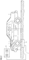
- the vehicle is decelerated very strongly during a test drive.
- the adapter 1 uses the in-vehicle sensor system in the form of a control unit 7, which controls the brake pressure on the brake line 8, and continuously reads out the brake pressure in the vehicle 4 by sending a query command and evaluating the respective reaction signal.
- the adapter-internal sensor system namely the 3D acceleration sensor 6, is used to determine the deceleration of the vehicle 4.
- adapter-external sensors in the form of a brake test bench 9 are used.
- the braking power 8 of the vehicle 4 is measured with the vehicle 4 on a brake test bench 9.
- the measurement data of the braking power 8 determined by the brake test bench 9 are transmitted to the adapter 1 via suitable interfaces 10 such as Bluetooth. Incidentally, these are also transmitted via a data display line 11 to a display device 12 of the brake test bench 9 and are displayed there.
- the adapter 1 uses the in-vehicle sensor system 7 during braking and continuously reads the brake pressure in the vehicle 4. This is done by sending a query command and evaluating the respective reaction signal.
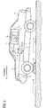
- FIG. 3 A shock absorber test using internal sensors 6 is shown.
- a vibration measurement is carried out after excitation by driving through an external physical excitation 13 in the form of a threshold, ramp or the like, by evaluating the decay behavior.
- the physical excitation 13 can also be carried out periodically by crossing a plurality of buckles 14 in order to resonate the vehicle body. Reaching the resonance depends, on the one hand, on the distance between the knuckles 14 and, on the other hand, the speed at which the vehicle 4 is crossing.
- the level of resonance allows statements to be made about the state of the axle damping.
- the vibration is recorded by means of a 3-axis acceleration and / or a 3-axis rotation rate sensor 6.
- the system is then evaluated for suitable vibration damper sizes, such as decay constant, damping factor or damping quality.
- the alignment of the adapter 1 in the car 4 itself is carried out by determining the gravitational acceleration vector and by the acceleration vector during the speed increase of the vehicle (positive acceleration).
- the values determined can be based on their quality or the assessability are classified. This is done by recognizing avoidable measuring errors or compensating for measuring errors using suitable mathematical methods. Such measurement errors can occur due to sloping driving, interference vibrations due to uneven road surface, incorrect calibration due to cornering or excessive speed. A clever evaluation is an axle or wheel specific Assignment or separation of the measured values possible.
- An advantage of the method according to the invention is the basic detectability of damage or defects on a large number of further vehicle assemblies, such as wheel suspension, spring damper mounting, springs and joints. In particular, a spring break can be seen. The method can also be used to detect and classify tire damage.
Landscapes
- Physics & Mathematics (AREA)
- General Physics & Mathematics (AREA)
- Measurement Of Mechanical Vibrations Or Ultrasonic Waves (AREA)
- Vehicle Body Suspensions (AREA)
Priority Applications (1)
| Application Number | Priority Date | Filing Date | Title |
|---|---|---|---|
| PL12158992T PL2500708T3 (pl) | 2011-03-16 | 2012-03-12 | Układ i sposób do testowania podzespołów, zwłaszcza do testowania amortyzacji osi, w pojazdach |
Applications Claiming Priority (2)
| Application Number | Priority Date | Filing Date | Title |
|---|---|---|---|
| DE102011005628 | 2011-03-16 | ||
| DE102012200194A DE102012200194A1 (de) | 2011-03-16 | 2012-01-09 | Anordnung und Verfahren zur Baugruppenprüfung, insbesondere zur Achsdämpfungsprüfung, in Fahrzeugen |
Publications (2)
| Publication Number | Publication Date |
|---|---|
| EP2500708A1 EP2500708A1 (de) | 2012-09-19 |
| EP2500708B1 true EP2500708B1 (de) | 2020-05-06 |
Family
ID=45992030
Family Applications (1)
| Application Number | Title | Priority Date | Filing Date |
|---|---|---|---|
| EP12158992.3A Active EP2500708B1 (de) | 2011-03-16 | 2012-03-12 | Anordnung und Verfahren zur Baugruppenprüfung, insbesondere zur Achsdämpfungsprüfung, in Fahrzeugen |
Country Status (6)
| Country | Link |
|---|---|
| EP (1) | EP2500708B1 (pl) |
| DE (1) | DE102012200194A1 (pl) |
| ES (1) | ES2804054T3 (pl) |
| LT (1) | LT2500708T (pl) |
| PL (1) | PL2500708T3 (pl) |
| PT (1) | PT2500708T (pl) |
Families Citing this family (11)
| Publication number | Priority date | Publication date | Assignee | Title |
|---|---|---|---|---|
| DE102012221491A1 (de) * | 2012-11-23 | 2014-05-28 | Brt Automotive Gmbh & Co Kg | Messanordnung und Verfahren zur Prüfung von Fahrwerken von Fahrzeugen |
| DE102013112976A1 (de) * | 2013-09-30 | 2015-04-02 | Hochschule für Technik und Wirtschaft Dresden | Anordnung und Verfahren zur Ermittlung von Fahrwerks- und anderen Eigenschaften eines Fahrzeugs |
| CN104021375B (zh) * | 2014-05-29 | 2017-11-07 | 银江股份有限公司 | 一种基于机器学习的车型识别方法 |
| DE102014226490A1 (de) * | 2014-12-18 | 2016-06-23 | Volkswagen Aktiengesellschaft | Vorrichtung und Verfahren zur Meldung einer extraordinären Beanspruchung eines Fahrwerkes eines Fortbewegungsmittels |
| DE102014119393B3 (de) | 2014-12-22 | 2016-05-12 | Fsd Fahrzeugsystemdaten Gmbh | Verfahren und Vorrichtung zur Ermittlung der dynamischen Radaufstandskraft |
| DE102015014840B4 (de) * | 2015-11-14 | 2021-12-16 | Audi Ag | Verfahren zum Prüfen einer elektrischen Parkbremse, Scheibenersatzstück sowie Messadapter |
| US10275955B2 (en) * | 2016-03-25 | 2019-04-30 | Qualcomm Incorporated | Methods and systems for utilizing information collected from multiple sensors to protect a vehicle from malware and attacks |
| DE102019135488A1 (de) * | 2019-12-20 | 2021-06-24 | Trumpf Werkzeugmaschinen Gmbh + Co. Kg | Verfahren und System zur Ermittlung des dynamischen Verhaltens einer Maschine |
| DE102020204918A1 (de) | 2020-04-17 | 2021-10-21 | Zf Friedrichshafen Ag | Verfahren zum Überprüfen eines Fahrwerks |
| DE102022209307B4 (de) | 2022-09-07 | 2023-08-03 | Zf Friedrichshafen Ag | Verfahren zur Zustandsüberwachung |
| CN119779707B (zh) * | 2024-12-27 | 2025-12-02 | 北京东方中科集成科技股份有限公司 | 智能悬架检测方法、装置和计算机设备 |
Citations (6)
| Publication number | Priority date | Publication date | Assignee | Title |
|---|---|---|---|---|
| DE4019501A1 (de) * | 1989-09-30 | 1991-04-11 | Lehn F Heinrich | Verfahren und vorrichtung zur schwingungsueberwachung der radsysteme von kraftfahrzeugen waehrend des fahrbetriebs |
| DE4440413A1 (de) * | 1994-11-11 | 1996-05-15 | Fichtel & Sachs Ag | Anordnung zur Überwachung der Wirksamkeit eines Fahrzeugstoßdämpfers |
| DE19814357A1 (de) * | 1998-03-31 | 1999-10-07 | Maha Gmbh & Co Kg | Meßgerät zur Fahrzeugdiagnose |
| WO2004024521A1 (de) * | 2002-08-27 | 2004-03-25 | Continental Teves Ag & Co. Ohg | Verfahren zur überwachung von fahrwerksfunktionen und fahrwerksbauteilen |
| DE10320809A1 (de) * | 2003-05-08 | 2004-11-25 | Conti Temic Microelectronic Gmbh | Verfahren zur Erkennung und Überwachung der Bewegung bei Fahrzeugen |
| US20110054733A1 (en) * | 2009-08-28 | 2011-03-03 | Hyundai Motor Company | Gravity sensor circuit system for vehicle |
Family Cites Families (6)
| Publication number | Priority date | Publication date | Assignee | Title |
|---|---|---|---|---|
| JP3518238B2 (ja) * | 1997-03-31 | 2004-04-12 | 株式会社豊田中央研究所 | 乗り心地評価装置 |
| DE19850079A1 (de) | 1998-10-30 | 2000-05-11 | Bosch Gmbh Robert | Verfahren und Anordnung zur Bremsenprüfung mittels Verzögerungsmessung bei Kraftfahrzeugen |
| CN1164917C (zh) * | 1999-07-13 | 2004-09-01 | 米其林技术公司 | 用于预测安装有悬挂系统的汽车的舒适性能的方法 |
| DE10258265A1 (de) | 2002-01-25 | 2003-08-21 | Continental Teves Ag & Co Ohg | Verfahren zur Überwachung von Feder-Dämpfersystemen |
| DE102004012143B3 (de) | 2004-03-12 | 2005-09-15 | Audi Ag | Verfahren zum Testen der Funktion von in einem Kraftfahrzeug eines bestimmten Typs verbauten, über einen Kommunikationsbus adressierbaren elektronischen und elektrischen Komponenten |
| DE202006019993U1 (de) | 2006-07-13 | 2007-07-12 | Berger Elektronik Ing.-Büro und Vertriebs GmbH | Diagnosegerät für Kraftfahrzeuge |
-
2012
- 2012-01-09 DE DE102012200194A patent/DE102012200194A1/de not_active Ceased
- 2012-03-12 PT PT121589923T patent/PT2500708T/pt unknown
- 2012-03-12 LT LTEP12158992.3T patent/LT2500708T/lt unknown
- 2012-03-12 ES ES12158992T patent/ES2804054T3/es active Active
- 2012-03-12 PL PL12158992T patent/PL2500708T3/pl unknown
- 2012-03-12 EP EP12158992.3A patent/EP2500708B1/de active Active
Patent Citations (6)
| Publication number | Priority date | Publication date | Assignee | Title |
|---|---|---|---|---|
| DE4019501A1 (de) * | 1989-09-30 | 1991-04-11 | Lehn F Heinrich | Verfahren und vorrichtung zur schwingungsueberwachung der radsysteme von kraftfahrzeugen waehrend des fahrbetriebs |
| DE4440413A1 (de) * | 1994-11-11 | 1996-05-15 | Fichtel & Sachs Ag | Anordnung zur Überwachung der Wirksamkeit eines Fahrzeugstoßdämpfers |
| DE19814357A1 (de) * | 1998-03-31 | 1999-10-07 | Maha Gmbh & Co Kg | Meßgerät zur Fahrzeugdiagnose |
| WO2004024521A1 (de) * | 2002-08-27 | 2004-03-25 | Continental Teves Ag & Co. Ohg | Verfahren zur überwachung von fahrwerksfunktionen und fahrwerksbauteilen |
| DE10320809A1 (de) * | 2003-05-08 | 2004-11-25 | Conti Temic Microelectronic Gmbh | Verfahren zur Erkennung und Überwachung der Bewegung bei Fahrzeugen |
| US20110054733A1 (en) * | 2009-08-28 | 2011-03-03 | Hyundai Motor Company | Gravity sensor circuit system for vehicle |
Also Published As
| Publication number | Publication date |
|---|---|
| EP2500708A1 (de) | 2012-09-19 |
| DE102012200194A1 (de) | 2012-09-20 |
| LT2500708T (lt) | 2020-10-26 |
| PL2500708T3 (pl) | 2020-12-28 |
| PT2500708T (pt) | 2020-07-07 |
| ES2804054T3 (es) | 2021-02-02 |
Similar Documents
| Publication | Publication Date | Title |
|---|---|---|
| EP2500708B1 (de) | Anordnung und Verfahren zur Baugruppenprüfung, insbesondere zur Achsdämpfungsprüfung, in Fahrzeugen | |
| DE102017112322B4 (de) | Computerimplementiertes Verfahren und Vorrichtung zur autonomen Überwachung der Intaktheit eines Fahrzeugs | |
| DE102018123821A1 (de) | Systeme und verfahren zur erfassung von störungen in einem fahrzeugfederungssystem | |
| DE102014113669A1 (de) | Verfahren zur Zustandsermittlung in einem Schienenfahrzeug | |
| WO2016102377A1 (de) | System und verfahren zur ermittlung wenigstens eines, eine abmessung eines reifenlatsches an einem reifen eines rades eines fahrzeuges charakterisierenden reifenlatschparameters | |
| DE102017221891B4 (de) | Verfahren zum Bestimmen eines Schadens, der bei einem Unfall zwischen einem Fahrzeug und einem Stoßpartner an dem Fahrzeug auftritt | |
| DE102012218426B4 (de) | Verfahren, Steuergerät und System zum Ermitteln eines, einen Zustand zumindest einer Komponente eines Kraftfahrzeugs kennzeichnenden Parameters | |
| EP2132548B1 (de) | Anordnung und verfahren zur erfassung und/oder auswertung von schwingungen bewegter und/oder einen antrieb aufweisender körper und/oder strukturen | |
| DE102008053005A1 (de) | Verfahren und System zur Beeinflussung der Bewegung eines in seinen Bewegungsabläufen steuerbaren oder regelbaren Fahrzeugaufbaus eines Kraftfahrzeuges und Fahrzeug | |
| DE10020521A1 (de) | Verfahren und Vorrichtung zum Überwachen des Fahrverhaltens von Schienenfahrzeugen | |
| EP2101156B1 (de) | Verfahren und Vorrichtung zum Überwachen von Fahrwerkregelsystemen | |
| DE102010038971A1 (de) | Verfahren und Vorrichtung zum Bewerten eines Zustands eines Fahrwerks eines Fahrzeugs | |
| EP3052919B1 (de) | Anordnung und verfahren zur ermittlung von fahrwerks- und anderen eigenschaften eines fahrzeugs | |
| DE112017007213T5 (de) | Fahrzeuginsassenerkennung | |
| DE102020211410B4 (de) | Verfahren zum Betreiben eines Gewichtserfassungssystems für ein Kraftfahrzeug oder einen Anhänger, entsprechendes Gewichtserfassungssystem und Kraftfahrzeug und Anhänger | |
| EP2801487A1 (de) | Anhängekupplung mit einer Auswerteeinrichtung | |
| DE102012219762A1 (de) | Verfahren und Vorrichtung zum Bewerten des Zustands mindestens eines Stoßdämpfers eines Fahrzeugs | |
| DE102015223970B4 (de) | Verfahren und Vorrichtung zur Bestimmung einer Radlast an einem Fahrzeugrad | |
| DE10062602B4 (de) | Verfahren und Vorrichtung zum Überwachen des Fahrverhaltens von Schienenfahrzeugen und zur Diagnose von Komponenten von Schienenfahrzeugen | |
| DE102013021875B4 (de) | Sensorvorrichtung und Verfahren zum Erzeugen von wegezustandsabhängig aufbereiteten Betätigungssignalen | |
| DE10337212B4 (de) | System und Verfahren zur Ermittlung eines Beladungszustandes eines Fahrzeugs oder eines Anhängers | |
| DE102018132952A1 (de) | Verfahren und vorrichtung zum erleichtern einer reifenkraftschätzung | |
| DE102014214995A1 (de) | Verfahren, Vorrichtung und System zum Betreiben eines Kraftfahrzeugs | |
| DE102018113462B4 (de) | Verfahren für die Erkennung einer defekten Dämpfervorrichtung eines Fahrzeugs | |
| EP2367155A1 (de) | Anordnung und Verfahren zur Fahrzeugzustandsuntersuchung |
Legal Events
| Date | Code | Title | Description |
|---|---|---|---|
| PUAI | Public reference made under article 153(3) epc to a published international application that has entered the european phase |
Free format text: ORIGINAL CODE: 0009012 |
|
| AK | Designated contracting states |
Kind code of ref document: A1 Designated state(s): AL AT BE BG CH CY CZ DE DK EE ES FI FR GB GR HR HU IE IS IT LI LT LU LV MC MK MT NL NO PL PT RO RS SE SI SK SM TR |
|
| AX | Request for extension of the european patent |
Extension state: BA ME |
|
| RAP1 | Party data changed (applicant data changed or rights of an application transferred) |
Owner name: FSD FAHRZEUGSYSTEMDATEN GMBH |
|
| 17P | Request for examination filed |
Effective date: 20130319 |
|
| 17Q | First examination report despatched |
Effective date: 20160308 |
|
| GRAP | Despatch of communication of intention to grant a patent |
Free format text: ORIGINAL CODE: EPIDOSNIGR1 |
|
| STAA | Information on the status of an ep patent application or granted ep patent |
Free format text: STATUS: GRANT OF PATENT IS INTENDED |
|
| INTG | Intention to grant announced |
Effective date: 20191126 |
|
| GRAS | Grant fee paid |
Free format text: ORIGINAL CODE: EPIDOSNIGR3 |
|
| RIN1 | Information on inventor provided before grant (corrected) |
Inventor name: USSATH, ROBERT Inventor name: BOENNINGER, JUERGEN Inventor name: STERNBERG, VOLKER Inventor name: DRECHSEL, FRANK |
|
| GRAA | (expected) grant |
Free format text: ORIGINAL CODE: 0009210 |
|
| STAA | Information on the status of an ep patent application or granted ep patent |
Free format text: STATUS: THE PATENT HAS BEEN GRANTED |
|
| AK | Designated contracting states |
Kind code of ref document: B1 Designated state(s): AL AT BE BG CH CY CZ DE DK EE ES FI FR GB GR HR HU IE IS IT LI LT LU LV MC MK MT NL NO PL PT RO RS SE SI SK SM TR |
|
| REG | Reference to a national code |
Ref country code: GB Ref legal event code: FG4D Free format text: NOT ENGLISH |
|
| REG | Reference to a national code |
Ref country code: AT Ref legal event code: REF Ref document number: 1267556 Country of ref document: AT Kind code of ref document: T Effective date: 20200515 Ref country code: CH Ref legal event code: EP |
|
| REG | Reference to a national code |
Ref country code: DE Ref legal event code: R096 Ref document number: 502012016044 Country of ref document: DE |
|
| REG | Reference to a national code |
Ref country code: IE Ref legal event code: FG4D Free format text: LANGUAGE OF EP DOCUMENT: GERMAN |
|
| REG | Reference to a national code |
Ref country code: PT Ref legal event code: SC4A Ref document number: 2500708 Country of ref document: PT Date of ref document: 20200707 Kind code of ref document: T Free format text: AVAILABILITY OF NATIONAL TRANSLATION Effective date: 20200630 |
|
| REG | Reference to a national code |
Ref country code: NL Ref legal event code: FP |
|
| REG | Reference to a national code |
Ref country code: SE Ref legal event code: TRGR |
|
| REG | Reference to a national code |
Ref country code: EE Ref legal event code: FG4A Ref document number: E019494 Country of ref document: EE Effective date: 20200714 |
|
| PG25 | Lapsed in a contracting state [announced via postgrant information from national office to epo] |
Ref country code: FI Free format text: LAPSE BECAUSE OF FAILURE TO SUBMIT A TRANSLATION OF THE DESCRIPTION OR TO PAY THE FEE WITHIN THE PRESCRIBED TIME-LIMIT Effective date: 20200506 Ref country code: NO Free format text: LAPSE BECAUSE OF FAILURE TO SUBMIT A TRANSLATION OF THE DESCRIPTION OR TO PAY THE FEE WITHIN THE PRESCRIBED TIME-LIMIT Effective date: 20200806 Ref country code: GR Free format text: LAPSE BECAUSE OF FAILURE TO SUBMIT A TRANSLATION OF THE DESCRIPTION OR TO PAY THE FEE WITHIN THE PRESCRIBED TIME-LIMIT Effective date: 20200807 Ref country code: IS Free format text: LAPSE BECAUSE OF FAILURE TO SUBMIT A TRANSLATION OF THE DESCRIPTION OR TO PAY THE FEE WITHIN THE PRESCRIBED TIME-LIMIT Effective date: 20200906 |
|
| PG25 | Lapsed in a contracting state [announced via postgrant information from national office to epo] |
Ref country code: BG Free format text: LAPSE BECAUSE OF FAILURE TO SUBMIT A TRANSLATION OF THE DESCRIPTION OR TO PAY THE FEE WITHIN THE PRESCRIBED TIME-LIMIT Effective date: 20200806 Ref country code: RS Free format text: LAPSE BECAUSE OF FAILURE TO SUBMIT A TRANSLATION OF THE DESCRIPTION OR TO PAY THE FEE WITHIN THE PRESCRIBED TIME-LIMIT Effective date: 20200506 Ref country code: HR Free format text: LAPSE BECAUSE OF FAILURE TO SUBMIT A TRANSLATION OF THE DESCRIPTION OR TO PAY THE FEE WITHIN THE PRESCRIBED TIME-LIMIT Effective date: 20200506 |
|
| PG25 | Lapsed in a contracting state [announced via postgrant information from national office to epo] |
Ref country code: AL Free format text: LAPSE BECAUSE OF FAILURE TO SUBMIT A TRANSLATION OF THE DESCRIPTION OR TO PAY THE FEE WITHIN THE PRESCRIBED TIME-LIMIT Effective date: 20200506 |
|
| PG25 | Lapsed in a contracting state [announced via postgrant information from national office to epo] |
Ref country code: SM Free format text: LAPSE BECAUSE OF FAILURE TO SUBMIT A TRANSLATION OF THE DESCRIPTION OR TO PAY THE FEE WITHIN THE PRESCRIBED TIME-LIMIT Effective date: 20200506 Ref country code: RO Free format text: LAPSE BECAUSE OF FAILURE TO SUBMIT A TRANSLATION OF THE DESCRIPTION OR TO PAY THE FEE WITHIN THE PRESCRIBED TIME-LIMIT Effective date: 20200506 Ref country code: DK Free format text: LAPSE BECAUSE OF FAILURE TO SUBMIT A TRANSLATION OF THE DESCRIPTION OR TO PAY THE FEE WITHIN THE PRESCRIBED TIME-LIMIT Effective date: 20200506 |
|
| REG | Reference to a national code |
Ref country code: ES Ref legal event code: FG2A Ref document number: 2804054 Country of ref document: ES Kind code of ref document: T3 Effective date: 20210202 |
|
| REG | Reference to a national code |
Ref country code: DE Ref legal event code: R097 Ref document number: 502012016044 Country of ref document: DE |
|
| PG25 | Lapsed in a contracting state [announced via postgrant information from national office to epo] |
Ref country code: SK Free format text: LAPSE BECAUSE OF FAILURE TO SUBMIT A TRANSLATION OF THE DESCRIPTION OR TO PAY THE FEE WITHIN THE PRESCRIBED TIME-LIMIT Effective date: 20200506 |
|
| PLBE | No opposition filed within time limit |
Free format text: ORIGINAL CODE: 0009261 |
|
| STAA | Information on the status of an ep patent application or granted ep patent |
Free format text: STATUS: NO OPPOSITION FILED WITHIN TIME LIMIT |
|
| 26N | No opposition filed |
Effective date: 20210209 |
|
| PG25 | Lapsed in a contracting state [announced via postgrant information from national office to epo] |
Ref country code: SI Free format text: LAPSE BECAUSE OF FAILURE TO SUBMIT A TRANSLATION OF THE DESCRIPTION OR TO PAY THE FEE WITHIN THE PRESCRIBED TIME-LIMIT Effective date: 20200506 |
|
| PG25 | Lapsed in a contracting state [announced via postgrant information from national office to epo] |
Ref country code: MC Free format text: LAPSE BECAUSE OF FAILURE TO SUBMIT A TRANSLATION OF THE DESCRIPTION OR TO PAY THE FEE WITHIN THE PRESCRIBED TIME-LIMIT Effective date: 20200506 |
|
| PG25 | Lapsed in a contracting state [announced via postgrant information from national office to epo] |
Ref country code: LU Free format text: LAPSE BECAUSE OF NON-PAYMENT OF DUE FEES Effective date: 20210312 |
|
| PG25 | Lapsed in a contracting state [announced via postgrant information from national office to epo] |
Ref country code: HU Free format text: LAPSE BECAUSE OF FAILURE TO SUBMIT A TRANSLATION OF THE DESCRIPTION OR TO PAY THE FEE WITHIN THE PRESCRIBED TIME-LIMIT; INVALID AB INITIO Effective date: 20120312 Ref country code: CY Free format text: LAPSE BECAUSE OF FAILURE TO SUBMIT A TRANSLATION OF THE DESCRIPTION OR TO PAY THE FEE WITHIN THE PRESCRIBED TIME-LIMIT Effective date: 20200506 |
|
| P01 | Opt-out of the competence of the unified patent court (upc) registered |
Effective date: 20230530 |
|
| PG25 | Lapsed in a contracting state [announced via postgrant information from national office to epo] |
Ref country code: MK Free format text: LAPSE BECAUSE OF FAILURE TO SUBMIT A TRANSLATION OF THE DESCRIPTION OR TO PAY THE FEE WITHIN THE PRESCRIBED TIME-LIMIT Effective date: 20200506 |
|
| PG25 | Lapsed in a contracting state [announced via postgrant information from national office to epo] |
Ref country code: MT Free format text: LAPSE BECAUSE OF FAILURE TO SUBMIT A TRANSLATION OF THE DESCRIPTION OR TO PAY THE FEE WITHIN THE PRESCRIBED TIME-LIMIT Effective date: 20200506 |
|
| PGFP | Annual fee paid to national office [announced via postgrant information from national office to epo] |
Ref country code: PT Payment date: 20250311 Year of fee payment: 14 |
|
| PGFP | Annual fee paid to national office [announced via postgrant information from national office to epo] |
Ref country code: LV Payment date: 20250325 Year of fee payment: 14 Ref country code: EE Payment date: 20250318 Year of fee payment: 14 |
|
| PGFP | Annual fee paid to national office [announced via postgrant information from national office to epo] |
Ref country code: PL Payment date: 20250303 Year of fee payment: 14 Ref country code: CZ Payment date: 20250227 Year of fee payment: 14 |
|
| PGFP | Annual fee paid to national office [announced via postgrant information from national office to epo] |
Ref country code: ES Payment date: 20250416 Year of fee payment: 14 |
|
| PGFP | Annual fee paid to national office [announced via postgrant information from national office to epo] |
Ref country code: IT Payment date: 20250331 Year of fee payment: 14 |
|
| PGFP | Annual fee paid to national office [announced via postgrant information from national office to epo] |
Ref country code: CH Payment date: 20250401 Year of fee payment: 14 |
|
| REG | Reference to a national code |
Ref country code: CH Ref legal event code: U11 Free format text: ST27 STATUS EVENT CODE: U-0-0-U10-U11 (AS PROVIDED BY THE NATIONAL OFFICE) Effective date: 20260401 |
|
| PGFP | Annual fee paid to national office [announced via postgrant information from national office to epo] |
Ref country code: SE Payment date: 20260323 Year of fee payment: 15 |
|
| PGFP | Annual fee paid to national office [announced via postgrant information from national office to epo] |
Ref country code: LT Payment date: 20260226 Year of fee payment: 15 Ref country code: GB Payment date: 20260324 Year of fee payment: 15 |
|
| PGFP | Annual fee paid to national office [announced via postgrant information from national office to epo] |
Ref country code: IE Payment date: 20260323 Year of fee payment: 15 Ref country code: DE Payment date: 20260323 Year of fee payment: 15 |
|
| PGFP | Annual fee paid to national office [announced via postgrant information from national office to epo] |
Ref country code: AT Payment date: 20260319 Year of fee payment: 15 |
|
| PGFP | Annual fee paid to national office [announced via postgrant information from national office to epo] |
Ref country code: BE Payment date: 20260323 Year of fee payment: 15 |
|
| PGFP | Annual fee paid to national office [announced via postgrant information from national office to epo] |
Ref country code: NL Payment date: 20260323 Year of fee payment: 15 |
|
| PGFP | Annual fee paid to national office [announced via postgrant information from national office to epo] |
Ref country code: FR Payment date: 20260325 Year of fee payment: 15 |
|
| PGFP | Annual fee paid to national office [announced via postgrant information from national office to epo] |
Ref country code: TR Payment date: 20260305 Year of fee payment: 15 |