EP2498331A2 - Funkfrequenzfilter - Google Patents
Funkfrequenzfilter Download PDFInfo
- Publication number
- EP2498331A2 EP2498331A2 EP10827183A EP10827183A EP2498331A2 EP 2498331 A2 EP2498331 A2 EP 2498331A2 EP 10827183 A EP10827183 A EP 10827183A EP 10827183 A EP10827183 A EP 10827183A EP 2498331 A2 EP2498331 A2 EP 2498331A2
- Authority
- EP
- European Patent Office
- Prior art keywords
- filter
- port
- coupler
- signal
- filter unit
- Prior art date
- Legal status (The legal status is an assumption and is not a legal conclusion. Google has not performed a legal analysis and makes no representation as to the accuracy of the status listed.)
- Granted
Links
Images


Classifications
-
- H—ELECTRICITY
- H03—ELECTRONIC CIRCUITRY
- H03H—IMPEDANCE NETWORKS, e.g. RESONANT CIRCUITS; RESONATORS
- H03H7/00—Multiple-port networks comprising only passive electrical elements as network components
- H03H7/46—Networks for connecting several sources or loads, working on different frequencies or frequency bands, to a common load or source
-
- H—ELECTRICITY
- H01—ELECTRIC ELEMENTS
- H01P—WAVEGUIDES; RESONATORS, LINES, OR OTHER DEVICES OF THE WAVEGUIDE TYPE
- H01P1/00—Auxiliary devices
- H01P1/20—Frequency-selective devices, e.g. filters
-
- H—ELECTRICITY
- H01—ELECTRIC ELEMENTS
- H01P—WAVEGUIDES; RESONATORS, LINES, OR OTHER DEVICES OF THE WAVEGUIDE TYPE
- H01P5/00—Coupling devices of the waveguide type
- H01P5/12—Coupling devices having more than two ports
- H01P5/16—Conjugate devices, i.e. devices having at least one port decoupled from one other port
- H01P5/19—Conjugate devices, i.e. devices having at least one port decoupled from one other port of the junction type
- H01P5/20—Magic-T junctions
-
- H—ELECTRICITY
- H01—ELECTRIC ELEMENTS
- H01P—WAVEGUIDES; RESONATORS, LINES, OR OTHER DEVICES OF THE WAVEGUIDE TYPE
- H01P5/00—Coupling devices of the waveguide type
- H01P5/12—Coupling devices having more than two ports
- H01P5/16—Conjugate devices, i.e. devices having at least one port decoupled from one other port
- H01P5/19—Conjugate devices, i.e. devices having at least one port decoupled from one other port of the junction type
- H01P5/22—Hybrid ring junctions
-
- H—ELECTRICITY
- H03—ELECTRONIC CIRCUITRY
- H03H—IMPEDANCE NETWORKS, e.g. RESONANT CIRCUITS; RESONATORS
- H03H7/00—Multiple-port networks comprising only passive electrical elements as network components
- H03H7/01—Frequency selective two-port networks
- H03H7/0138—Electrical filters or coupling circuits
-
- H—ELECTRICITY
- H03—ELECTRONIC CIRCUITRY
- H03H—IMPEDANCE NETWORKS, e.g. RESONANT CIRCUITS; RESONATORS
- H03H7/00—Multiple-port networks comprising only passive electrical elements as network components
- H03H7/48—Networks for connecting several sources or loads, working on the same frequency or frequency band, to a common load or source
-
- H—ELECTRICITY
- H01—ELECTRIC ELEMENTS
- H01P—WAVEGUIDES; RESONATORS, LINES, OR OTHER DEVICES OF THE WAVEGUIDE TYPE
- H01P1/00—Auxiliary devices
- H01P1/20—Frequency-selective devices, e.g. filters
- H01P1/201—Filters for transverse electromagnetic waves
- H01P1/203—Strip line filters
-
- H—ELECTRICITY
- H03—ELECTRONIC CIRCUITRY
- H03H—IMPEDANCE NETWORKS, e.g. RESONANT CIRCUITS; RESONATORS
- H03H11/00—Networks using active elements
- H03H11/02—Multiple-port networks
- H03H11/36—Networks for connecting several sources or loads, working on the same frequency band, to a common load or source
-
- H—ELECTRICITY
- H04—ELECTRIC COMMUNICATION TECHNIQUE
- H04B—TRANSMISSION
- H04B1/00—Details of transmission systems, not covered by a single one of groups H04B3/00 - H04B13/00; Details of transmission systems not characterised by the medium used for transmission
- H04B1/38—Transceivers, i.e. devices in which transmitter and receiver form a structural unit and in which at least one part is used for functions of transmitting and receiving
- H04B1/40—Circuits
- H04B1/54—Circuits using the same frequency for two directions of communication
- H04B1/58—Hybrid arrangements, i.e. arrangements for transition from single-path two-direction transmission to single-direction transmission on each of two paths or vice versa
Definitions
- the present invention relates to a Radio Frequency (RF) filter.
- RF Radio Frequency
- a filter is an essential part of an RF system, for passing or rejecting a predetermined frequency band.
- Filters are classified into Band Pass Filters (BPFs), Band Rejection Filters (BRFs), High Pass Filters (HPFs), Low Pass Filters (LPFs), etc.
- BPFs Band Pass Filters
- BRFs Band Rejection Filters
- HPFs High Pass Filters
- LPFs Low Pass Filters
- Such filters are designed so as to satisfy frequency pass or rejection characteristics required for the RF system. Once the filters are installed, their characteristics are difficult to change unless they are replaced. For example, when a BRF is to be reinstalled in an RF system equipped with a BPF, the BPF should be removed and then replaced with the BRF. The filter replacement may lead to communication disconnection and increase cost.
- the BRF is designed by connecting resonators using a 50-ohm ( ⁇ ) line.
- ⁇ 50-ohm
- a frequency band equal to or wider than a predetermined bandwidth cannot be rejected.
- the total length of the 50-ohm line also increases, thereby increasing path loss.
- Another shortcoming of the BRF is that a low or high frequency band is selectively rejected with respect to a specific frequency and thus it is difficult to improve band edge characteristics.
- An aspect of embodiments of the present invention is to address at least the problems and/or disadvantages and to provide at least the advantages described below. Accordingly, an aspect of embodiments of the present invention is to provide an RF filter for decreasing path loss.
- Another aspect of embodiments of the present invention provides an RF filter for improving band edge characteristics.
- Another aspect of embodiments of the present invention provides an RF filter for inverting a signal characteristic easily.
- Another aspect of embodiments of the present invention provides an RF filter for rejecting a wide frequency band by increasing coupling between resonators.
- a further aspect of embodiments of the present invention provides an RF filter for facilitating design of notch characteristics.
- an RF filter in which a coupler receives an input signal through a first port, divides the input signal, outputs the divided signals through second and third ports, combines signals received through the second and third ports according to phases of the signals, and outputs the combined signal through the first port or as an output signal of the RF filter through a fourth port, and a first filter unit has a first port connected to the second port of the coupler and a second port connected to the third port of the coupler, for having a predetermined frequency filtering characteristic.
- the present invention provides a new filter by combining a filter with a hybrid coupler, it can reduce the path loss of a signal, improve band edge characteristics, easily invert signal characteristics, reject a wide frequency band by increasing coupling between resonators, and facilitate design of notch characteristics.
- a so-called chameleon filter which is configured by combining a hybrid coupler with a filter and thus has new characteristics modified from original characteristics.
- a Band Pass Filter (BPF) and a hybrid coupler may be combined into a chameleon Band Rejection Filter (BRF) and a Low Pass Filter (LPF) and a hybrid coupler may be combined into a chameleon HPF, or vice versa in the present invention.
- BPF Band Pass Filter
- BRF chameleon Band Rejection Filter
- LPF Low Pass Filter
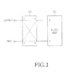
- FIG. 1 illustrates the structure of a chameleon filter according to an embodiment of the present invention.
- a 3-dB hybrid coupler 110 is connected to a filter unit 120 in the chameleon filter according to the embodiment of the present invention. That is, the filter of the present invention is configured so that a first port of the hybrid coupler 110 serves as an input port of the chameleon filter, a fourth port of the hybrid coupler 110 serves as an output port of the chameleon filter, a second port of the hybrid coupler 110 is connected to a first port (e.g. an input port) of the filter unit 120, and a third port of the hybrid coupler 110 is connected to a second port (e.g. an output port) of the filter unit 120.
- the filter unit 120 may be configured with various types of filters such as a BPF, BRF, High Pass Filter (HPF), LPF, etc. If the filter unit 120 is configured with a BPF, the chameleon filter has BRF characteristics.
- FIG. 5A illustrates the waveforms of a signal S 21 passed through the general BPF and a signal S 11 returned from the general BPF.
- FIG. 5B illustrates the waveforms of signals in the chameleon filter of the present invention in which the hybrid coupler 110 is combined with the filter unit 120 configured with a BPF in an RF system.
- the phases of the passed signal S 21 and the returned signal S 11 are inverted in FIG. 5B . Therefore, although the filter unit 120 is configured with a BPF in the chameleon filter of the present invention, its overall characteristics are BRF characteristics.
- a hybrid coupler generally functions to equally divide signal power with a phase difference of 90 degrees. For example, when a signal is input to the first port of the hybrid coupler 110, the power of the signal is equally divided into two parts with a 90-degree phase difference and then provided to the first and second ports of the filter unit 120 through the second port (0 degrees) and the third port (-90 degrees) of the hybrid coupler 110. Signals in the pass band of the filter unit 120 pass through the filter unit 120 and are fed back to the opposite ports, that is, the third and second ports of the hybrid coupler 110. Then the signals are combined due to the phase difference and output to the first port of the hybrid coupler 110, with no signal output to the fourth port of the hybrid coupler 110.
- signals outside the pass band of the filter unit 120 do not pass through the filter unit 120, return from the first and second ports of the filter unit 120, and then are fed back to the second and third ports of the hybrid coupler 110, respectively. These signals are combined due to the phase difference and output to the fourth port of the hybrid coupler 110.
- a signal of the pass band of the filter unit 120 in a signal input to the input port of the chameleon filter i.e. the first port of the hybrid coupler
- a signal outside the pass band of the filter unit 120 in the input signal is output to the output port of the chameleon filter (i.e. the fourth port of the hybrid coupler) in the whole filter structure.
- Parts that divide/combine the power of signals according to their phase difference include a hybrid ring, a branchline directional coupler, a 3-dB directional coupler, a magic T, etc. If such a part is used instead of the hybrid coupler 110, it may be configured so as to adjust the phase of a signal using a phase shifter additionally. For example, if a magic T substitutes for the hybrid coupler 110, a phase shifter is provided on a connection path between a second port (or third port) of the magic T and the filter unit, to thereby shift the phase of a passed signal by 90 degrees.
- the chameleon filter having the above configuration according to the present invention is designed to operate as a BRF on the whole, that is, in a 'hybrid coupler+BPF' structure, it is more useful. That is, a typical BRF is designed by connecting resonators with one another via a 50-ohm ( ⁇ ) line. This structure requires a relatively large size and is complex. In addition, since much coupling does not occur between resonators, the BRF has limitations in rejecting a frequency band having a predetermined or wider bandwidth. In contrast, the chameleon filter of the present invention is relatively easily implemented and facilitates realization of a BRF using a BPF structure that can process a wide frequency band. The chameleon filter of the present invention can remarkably reduce path loss that may be caused as the total length of the 50-ohm line increases.
- the 50-ohm line should be lengthened or shortened with respect to a corresponding frequency in order to achieve notch characteristics in the general BRF.
- the chameleon filter of the present invention realizes notch characteristics in the BPF and thus implements the BRF on the whole using the notch characteristics. Hence, the notch characteristics of the BRF are easily achieved and skirt characteristics can be improved.
- the chameleon filter of the present invention can realize an HPF structure on the whole using an LPF structure.
- an HPF which is relatively difficult to fabricate can be easily implemented.
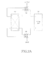
- FIGs. 2A to 2D illustrate the structure of a chameleon filter according to another embodiment of the present invention.
- the chameleon filter according to the second embodiment of the present invention includes a hybrid coupler 210, a filter unit 220, and first and second switch units 240 and 230.
- the hybrid coupler 210 and the filter unit 220 may be identical to their counterparts in the embodiment illustrated in FIG. 1 .
- the first and second switch units 240 and 230 each may have a combination of general single on/off switches, or a combination of a Double Pole Double Throw (DPDT) switch and a general single on/off switch, which establishes a signal connection path dynamically according to an external switching control signal so that the input and output ports of the chameleon filter are connected directly to the filter unit ( FIG. 2A ), the input and output ports of the chameleon filter are connected to the filter unit indirectly via the hybrid coupler 210 ( FIG. 2B ), a signal passes through the hybrid coupler 210 ( FIG. 2C ), and a signal bypasses the hybrid coupler 210 and the filter unit 220 ( FIG. 2D ).
- DPDT Double Pole Double Throw
- FIG. 2A illustrates the structure of a chameleon filter according to the present invention, when the chameleon filter operates as a BPF
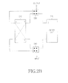
- FIG. 2B illustrates the structure of a chameleon filter according to the present invention, when the chameleon filter operates as a BRF.
- the chameleon filter of the present invention operates as a BPF
- the signal is output to an output port through the filter unit 220 configured with a BPF and the second switch unit 230. Therefore, there is no signal input and output to and from the hybrid coupler 210 and the chameleon filter of the present invention is used to pass a predetermined frequency band.
- the first and second switch units 240 and 230 switch in a different manner from in FIG. 2A , such that a path is established to pass input and output signals through the hybrid coupler 210.
- the signal When a signal is input to the input port of the first switch unit 240, the signal is provided to a first port of the hybrid coupler 210, equally divided into two signals each having a half power with a phase difference of 90 degrees, and then output through second and third ports of the hybrid coupler 210. Signals of the pass band of the filter unit 220 in the divided two signals pass through the filter unit 220 and the first and second switches 240 and 230, whereas signals outside the pass band of the filter unit 220 in the divided two signals are reflected from the filter unit 220 and fed back to the second and third ports of the hybrid coupler 210. Signals of the pass band of the filter unit 220 in these input signals are output through the fourth port of the hybrid coupler 210. The signals output from the fourth port of the hybrid coupler 210 are output to the output port via the second switch 230.
- an input signal is input only to the hybrid coupler 210.
- the input signal bypasses the filter unit 220.
- a signal input to the first port of the hybrid coupler 210 is divided into two signals each having an equal half power, with a phase difference of 90 degrees.
- the divided signals are output through the second and third ports of the hybrid coupler 210, fully reflected from the first and second switches 240 and 230, and then fed back to the second and third ports of the hybrid coupler 210.
- These signals are combined due to the phase difference and then output through the fourth port of the hybrid coupler 210.
- the signal output from the fourth port of the hybrid coupler 210 is just output through the second switch 230.
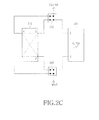
- the structure illustrated in FIG. 2C simply outputs an input signal without any signal processing.
- the input signal bypasses the filter unit 220 without being filtered.
- a signal bypasses the filter unit 220.
- a signal input to the input port of the first switch 240 bypasses the filter unit 220 or the hybrid coupler 210 in a bypass path and is output to the output port via the second switch 230.
- the filter of the present invention may be appropriate for a wireless communication system in which filter is not required in an initial use environment and then required in a subsequent use environment.
- a mobile communication BS system should return a part of a used frequency band on a service provider basis. For example, a specific service provider may use 800 to 825MHz in a current year and then may use only 810 to 825MHz in the next year. That is, the service provider should return the frequency band from 800MHz to below 810MHz.
- the service provider should install a BRF that rejects the frequency band from 800MHz to below 810MHz or a BPF that passes only 810 to 825MHz in every BS. It is almost impossible to simultaneously install the filters in all BSs distributed nationwide. Therefore, the filters are sequentially installed in the BSs over a relative long period (e.g. 6 months) before the next year.
- BSs in which filters are installed early cannot service the frequency band from 800MHz to below 810MHz.
- use of the filter according to the present invention enables signal bypassing despite the preliminary filter installation in the BS.
- an entire serviceable band can be used in the current year.
- signals pass through the filters through switching control of the filters in the BSs so that the service band of all BSs may be changed to 810 to 825MHz almost simultaneously.
- FIGs. 2A to 2D have been described in the context of the filter unit 220 being a BPF, it is clearly understood that the BPF may be replaced with another filter such as a BRF, an HPF, an LPF, etc.
- FIG. 3 illustrates the structure of a chameleon filter according to a third embodiment of the present invention.
- the chameleon filter according to the third embodiment of the present invention includes a hybrid coupler 310 and a filter unit 320. While the filter units may be configured with a single filter in the first and second embodiments of the present invention, the filter unit 320 includes at least two identical filters, that is, first and second filters 3210 and 3220. The filter unit 320 further includes a phase shifter 3230.
- the chameleon filter according to the third embodiment of the present invention is configured such that a first port of the hybrid coupler 310 serves as an input port of the chameleon filter, a fourth port of the hybrid coupler 310 serves as an output port of the chameleon filter, a second port of the hybrid coupler 310 is connected to a first port (e.g. an input port) of the first filter 3210, and a third port of the hybrid coupler 310 is connected to a first port (e.g. an input port) of the second filter 3220.
- a second port (e.g. an output port) of the first filter 3210 is opened and a second port (e.g. an output port) of the second filter 3220 is connected to an end of the phase shifter 3230. The other end of the phase shifter 3230 is opened.
- a signal input to the hybrid coupler 310 through the first port is equally divided into two signals each having a half power, with a phase difference of 90 degrees and output through the second and third ports of the hybrid coupler 310.
- Signals of the pass bands of the first and second filters 3210 and 3220 in the output signals are input to the first and second filters 3210 and 3220 and signals outside the pass bands of the first and second filters 3210 and 3220 are reflected from the first and second filters 3210 and 3220.
- the first and second filters 3210 and 3220 may be the same types of filters, such as BPFs, BRFs, HPFs, LPFs, etc.
- Signals outside the pass bands of the first and second filter 3210 and 3220 are reflected from the first and second filter 3210 and 3220, fed back to the second and third ports of the hybrid coupler 310, and then output through the fourth port of the hybrid coupler 310.
- the phase variation of a signal of the pass band passed through the second filter 3220 can be adjusted dynamically.
- the signal in the pass band of the second filter 3220 is phase-shifted in the phase shifter 3230, reflected from the open port of the phase shifter 3230, and fed back to the third port of the hybrid coupler 310 through the second filter 3220.
- the signal in the pass band of the first filter 3210 is reflected from the open port of the first filter 3210 and fed back to the second port of the hybrid coupler 310.
- the phase difference between the signals is not accurately 90 degrees. Consequently, the signals are divided into the first and fourth ports of the hybrid coupler 310 according to the phase difference.
- the chameleon filter operates as a BRF on the whole and the loss bandwidth (dB) of a signal in a rejection band of the chameleon filter is changed according to a phase variation controlled by the phase shifter 3230.
- This chameleon filter is applicable to a system in which the rejected amount of a signal in a rejection band needs to be adjusted.
- FIG. 4 illustrates the structure of a chameleon filter according to a fourth embodiment of the present invention.
- the chameleon filter according to the fourth embodiment of the present invention includes a first filter unit 420, a hybrid coupler 410, and a second filter unit 430 and has a low signal loss equal to or smaller than a predetermined threshold.
- the chameleon filter is similar to the chameleon filter according to the first embodiment, except that the second filter unit 430 is further installed between a fourth port of the hybrid coupler 410 and an output port of the chameleon filter.
- the number of resonators may differ for the first and second filter units 420 and 430.
- the second filter unit 430 may be configured with a 6-stage BPF and the first filter unit 420 may be configured with a 4-stage BPF.
- the hybrid coupler 410 and the first filter unit 420 in combination may create BRF characteristics. That is, the chameleon filter according to the fourth embodiment of the present invention is a combination of a BPF structure and a BRF structure. If the rejection band of the BRF structure is positioned at one band edge of the BPF, this structure may have less signal loss and similar or improved characteristics of one band edge, for example, compared to a 10-stage BPF structure.
- first and second filter units 420 and 430 may be replaced with various filters other than BPFs, such as BRFs, HPFs, LPFs, etc. While it has been described in FIGs. 1 to 4 that the chameleon filters are configured with filters (i.e. indicated by reference numerals 120, 220, 320, 330, 410 and 430), other mobile communication parts may be used instead of the filters 120, 220, 320, 330, 410 and 430, to thereby achieve a similar function to the function of a chameleon filter.
Landscapes
- Control Of Motors That Do Not Use Commutators (AREA)
Priority Applications (1)
| Application Number | Priority Date | Filing Date | Title |
|---|---|---|---|
| EP15150944.5A EP2884578B1 (de) | 2009-11-02 | 2010-11-02 | Funkfrequenzfilter |
Applications Claiming Priority (2)
| Application Number | Priority Date | Filing Date | Title |
|---|---|---|---|
| US25710209P | 2009-11-02 | 2009-11-02 | |
| PCT/KR2010/007677 WO2011053099A2 (ko) | 2009-11-02 | 2010-11-02 | 무선 주파수 필터 |
Related Child Applications (2)
| Application Number | Title | Priority Date | Filing Date |
|---|---|---|---|
| EP15150944.5A Division-Into EP2884578B1 (de) | 2009-11-02 | 2010-11-02 | Funkfrequenzfilter |
| EP15150944.5A Division EP2884578B1 (de) | 2009-11-02 | 2010-11-02 | Funkfrequenzfilter |
Publications (3)
| Publication Number | Publication Date |
|---|---|
| EP2498331A2 true EP2498331A2 (de) | 2012-09-12 |
| EP2498331A4 EP2498331A4 (de) | 2013-05-15 |
| EP2498331B1 EP2498331B1 (de) | 2015-04-15 |
Family
ID=43922919
Family Applications (2)
| Application Number | Title | Priority Date | Filing Date |
|---|---|---|---|
| EP15150944.5A Active EP2884578B1 (de) | 2009-11-02 | 2010-11-02 | Funkfrequenzfilter |
| EP10827183.4A Active EP2498331B1 (de) | 2009-11-02 | 2010-11-02 | Funkfrequenzfilter |
Family Applications Before (1)
| Application Number | Title | Priority Date | Filing Date |
|---|---|---|---|
| EP15150944.5A Active EP2884578B1 (de) | 2009-11-02 | 2010-11-02 | Funkfrequenzfilter |
Country Status (6)
| Country | Link |
|---|---|
| US (2) | US8749321B2 (de) |
| EP (2) | EP2884578B1 (de) |
| JP (1) | JP5493002B2 (de) |
| KR (1) | KR101756116B1 (de) |
| CN (2) | CN102576923B (de) |
| WO (1) | WO2011053099A2 (de) |
Families Citing this family (28)
| Publication number | Priority date | Publication date | Assignee | Title |
|---|---|---|---|---|
| KR101859230B1 (ko) * | 2011-12-26 | 2018-05-18 | 한국전자통신연구원 | 무선 통신 시스템에서의 수동 소자를 이용한 고주파 송수신 전치단 장치 |
| KR101545139B1 (ko) * | 2012-10-19 | 2015-08-20 | 한국전기연구원 | Lpn 필터를 이용한 전력계통의 위상추종 시스템 |
| CN105103462A (zh) | 2012-12-11 | 2015-11-25 | 南加利福尼亚大学 | 用于双工器和共存无线通信系统的无源泄露抵消网络 |
| US9425840B2 (en) * | 2013-04-26 | 2016-08-23 | Northrop Grumman Systems Corporation | Wideband tunable notch cancellation |
| US9608688B2 (en) | 2013-09-26 | 2017-03-28 | Qorvo Us, Inc. | High linearity RF diplexer |
| US9899986B2 (en) * | 2013-10-24 | 2018-02-20 | Qoro US, Inc. | RF diplexer |
| US9985682B2 (en) | 2013-10-24 | 2018-05-29 | Qorvo Us, Inc. | Broadband isolation low-loss ISM/MB-HB tunable diplexer |
| CN105814737B (zh) | 2013-12-10 | 2019-06-04 | 南加利福尼亚大学 | 增强混合式抵消网络和双工器中的隔离和阻抗匹配 |
| WO2015123668A1 (en) | 2014-02-14 | 2015-08-20 | University Of Southern California | Hybrid-based cancellation in presence of antenna mismatch |
| US9843302B2 (en) | 2014-02-14 | 2017-12-12 | University Of Southern California | Reflection and hybrid reflection filters |
| WO2015127097A1 (en) * | 2014-02-19 | 2015-08-27 | University Of Southern California | Miniature acoustic resonator-based filters and duplexers |
| JP6539119B2 (ja) * | 2014-06-13 | 2019-07-03 | 住友電気工業株式会社 | 電子装置 |
| JP2016066884A (ja) * | 2014-09-24 | 2016-04-28 | 住友電気工業株式会社 | フィルタ装置 |
| US9941908B2 (en) * | 2014-10-20 | 2018-04-10 | Infineon Technologies Ag | System and method for a radio frequency filter |
| US10581650B2 (en) | 2015-09-08 | 2020-03-03 | Qorvo Us, Inc. | Enhancing isolation in radio frequency multiplexers |
| US9912326B2 (en) | 2015-09-08 | 2018-03-06 | Abtum Inc. | Method for tuning feed-forward canceller |
| US9866201B2 (en) | 2015-09-08 | 2018-01-09 | Abtum Inc. | All-acoustic duplexers using directional couplers |
| US9762416B2 (en) | 2015-09-08 | 2017-09-12 | Abtum Inc. | Reflection coefficient reader |
| WO2017053875A1 (en) * | 2015-09-23 | 2017-03-30 | The Government Of The United States Of America, As Represented By The Secretary Of The Navy | Switched bandstop filter with low-loss linear-phase bypass state |
| US9755668B2 (en) | 2015-09-30 | 2017-09-05 | Abtum Inc. | Radio frequency complex reflection coefficient reader |
| US10038458B2 (en) | 2015-10-06 | 2018-07-31 | Abtum Inc. | Reflection-based radio-frequency multiplexers |
| US10476530B2 (en) | 2015-10-12 | 2019-11-12 | Qorvo Us, Inc. | Hybrid-coupler-based radio frequency multiplexers |
| US10373794B2 (en) | 2015-10-29 | 2019-08-06 | Lam Research Corporation | Systems and methods for filtering radio frequencies from a signal of a thermocouple and controlling a temperature of an electrode in a plasma chamber |
| US10855246B2 (en) | 2016-09-21 | 2020-12-01 | Qorvo Us, Inc. | Enhancing isolation in hybrid-based radio frequency duplexers and multiplexers |
| US10181833B2 (en) * | 2017-03-16 | 2019-01-15 | Infineon Technologies Ag | Reflection type phase shifter with active device tuning |
| JP2020098969A (ja) * | 2018-12-17 | 2020-06-25 | 株式会社村田製作所 | 90゜ハイブリッドカプラを用いたフィルタ回路 |
| WO2020139407A1 (en) * | 2018-12-28 | 2020-07-02 | Google Llc | Attenuator for qubit drive signals |
| CN111970727A (zh) * | 2020-07-15 | 2020-11-20 | 国家无线电监测中心检测中心 | 一种NB-IoT基站的阻塞测试系统 |
Family Cites Families (24)
| Publication number | Priority date | Publication date | Assignee | Title |
|---|---|---|---|---|
| US3435384A (en) * | 1965-05-28 | 1969-03-25 | Gen Telephone & Elect | Waveguide filter |
| WO1987002187A1 (en) * | 1985-10-03 | 1987-04-09 | Hughes Aircraft Company | Broadband, high isolation radial line power divider/combiner |
| SU1363332A1 (ru) * | 1986-04-08 | 1987-12-30 | Предприятие П/Я Г-4173 | Частотно-селективное СВЧ-устройство |
| FR2607639B1 (fr) | 1986-11-28 | 1995-03-03 | Thomson Csf | Rejecteur de bande a grande selectivite, et utilisation d'un tel rejecteur |
| JPS63206029A (ja) | 1987-02-21 | 1988-08-25 | Nec Corp | 帯域通過ろ波器 |
| CN86204681U (zh) * | 1987-10-10 | 1988-06-29 | 上海市广播科学研究所 | 调频多工器 |
| US4963945A (en) * | 1989-04-07 | 1990-10-16 | Plessey Electronic Systems Corp. | Band rejection filtering arrangement |
| US5508661A (en) * | 1991-10-24 | 1996-04-16 | Litton Industries | Fast tuning YIG frequency synthesizer |
| GB2284311B (en) | 1993-11-24 | 1998-03-04 | Filtronic Ltd | Hybrid notch filter |
| GB2297459A (en) | 1995-01-26 | 1996-07-31 | Airtech Ltd | A mast head device |
| JP4343374B2 (ja) | 2000-01-13 | 2009-10-14 | 株式会社アドバンテスト | シングルバランスミキサ |
| KR100500663B1 (ko) * | 2002-11-18 | 2005-07-12 | 한국전자통신연구원 | 직교신호 발생기를 이용한 선택적 결합기형 디지털위상변위기 |
| DE10304524A1 (de) * | 2003-02-04 | 2004-08-12 | Tesat-Spacecom Gmbh & Co.Kg | Topologie für Bandpassfilter |
| CN2718802Y (zh) * | 2004-01-20 | 2005-08-17 | 陈意辉 | 桥式合成型高隔离大功率多路分米波邻频多工合成器 |
| JP2005311738A (ja) | 2004-04-22 | 2005-11-04 | Nippon Dengyo Kosaku Co Ltd | 並列運転形ハイブリッド回路およびcib形合波器 |
| KR100573395B1 (ko) | 2004-06-28 | 2006-04-25 | 안달 | 저역통과 여파기를 일체로 구비한 90도 하이브리드 결합기 |
| CN1671068A (zh) * | 2005-03-24 | 2005-09-21 | 南开大学 | 高温超导微波滤波群时延均衡器 |
| FI20055161A0 (fi) * | 2005-04-08 | 2005-04-08 | Nokia Corp | Diversiteettivastaanotto samaan asennuspaikkaan sijoitetuille tukiasemille |
| US7623005B2 (en) * | 2005-05-11 | 2009-11-24 | Telefonaktiebolaget L M Ericsson (Publ) | Filter combiner |
| JP4105726B2 (ja) * | 2006-01-31 | 2008-06-25 | 日本電業工作株式会社 | 帯域阻止フィルタ |
| US7675388B2 (en) * | 2006-03-07 | 2010-03-09 | Agile Rf, Inc. | Switchable tunable acoustic resonator using BST material |
| JP5075209B2 (ja) | 2007-12-18 | 2012-11-21 | 太陽誘電株式会社 | デュプレクサ、およびデュプレクサを含むモジュール、通信機器 |
| KR101099816B1 (ko) | 2009-06-15 | 2011-12-27 | 엘지이노텍 주식회사 | 대역 통과 필터 및 대역 차단 필터 |
| US8264298B2 (en) * | 2009-10-01 | 2012-09-11 | Unidyne, Inc. | Filtering device and a method for filtering a signal |
-
2010
- 2010-11-02 EP EP15150944.5A patent/EP2884578B1/de active Active
- 2010-11-02 WO PCT/KR2010/007677 patent/WO2011053099A2/ko not_active Ceased
- 2010-11-02 CN CN201080048680.4A patent/CN102576923B/zh active Active
- 2010-11-02 CN CN201510396657.9A patent/CN104966864B/zh active Active
- 2010-11-02 US US12/917,917 patent/US8749321B2/en active Active
- 2010-11-02 JP JP2012534128A patent/JP5493002B2/ja active Active
- 2010-11-02 KR KR1020127011967A patent/KR101756116B1/ko active Active
- 2010-11-02 EP EP10827183.4A patent/EP2498331B1/de active Active
-
2014
- 2014-05-14 US US14/277,449 patent/US9564871B2/en active Active
Also Published As
| Publication number | Publication date |
|---|---|
| EP2498331A4 (de) | 2013-05-15 |
| EP2498331B1 (de) | 2015-04-15 |
| KR101756116B1 (ko) | 2017-07-11 |
| CN102576923A (zh) | 2012-07-11 |
| JP2013509019A (ja) | 2013-03-07 |
| US20110140803A1 (en) | 2011-06-16 |
| KR20120113707A (ko) | 2012-10-15 |
| US20140247098A1 (en) | 2014-09-04 |
| CN102576923B (zh) | 2015-08-26 |
| EP2884578B1 (de) | 2018-08-15 |
| CN104966864A (zh) | 2015-10-07 |
| WO2011053099A2 (ko) | 2011-05-05 |
| US8749321B2 (en) | 2014-06-10 |
| JP5493002B2 (ja) | 2014-05-14 |
| WO2011053099A3 (ko) | 2011-09-15 |
| US9564871B2 (en) | 2017-02-07 |
| CN104966864B (zh) | 2018-03-06 |
| EP2884578A1 (de) | 2015-06-17 |
Similar Documents
| Publication | Publication Date | Title |
|---|---|---|
| EP2884578B1 (de) | Funkfrequenzfilter | |
| US6107898A (en) | Microwave channelized bandpass filter having two channels | |
| US10735045B2 (en) | Diplexer circuit | |
| KR20100136160A (ko) | Rf 프론트 앤드 모듈 및 이를 이용한 멀티밴드 통신 모듈 | |
| CN109638476B (zh) | 馈电网络和双波束天线 | |
| JP2004096399A (ja) | 並列多段型帯域通過フィルタ | |
| US20090069053A1 (en) | Apparatus for Using a Wireless Communication Base Station in Common | |
| EP1780828B1 (de) | Frequenzdiplexer mit einem Eingang und erstem und zweitem Ausgang. | |
| EP1889373B1 (de) | Bypass-anordnung eines rauscharmen verstärkers | |
| KR20110093315A (ko) | 바이패스 경로를 갖는 무선 주파수 필터 | |
| US10027307B2 (en) | Ultra broadband network of fixed or switched frequency selective filters | |
| CN115732879A (zh) | 一种具有无反射特性的平衡-不平衡一分三滤波功分器 | |
| CN116736348A (zh) | 一种射频前端电路及卫星导航系统 | |
| CN110995198B (zh) | 一种小型化快速可重构式预选器装置 | |
| KR102906919B1 (ko) | 동위상 전력 분배기와 역위상 발룬의 이중 기능을 갖는 마이크로파 전력 분배 장치 | |
| JP3787904B2 (ja) | アンテナスイッチ共用器 | |
| CN113726365B (zh) | 双路器、射频通信电路及设备 | |
| JPWO2013085029A1 (ja) | アンテナ共用器 | |
| CN113922015B (zh) | 频率和扫描角连续可调的滤波可重构波束形成网络 | |
| JP2003209414A (ja) | 高周波電力分配合成回路 | |
| JP4367423B2 (ja) | 高周波スイッチ | |
| WO2002067359A1 (fr) | Circuit de traitement de signaux | |
| WO2019228860A1 (en) | Multiplexer circuit with improved isolation and multiplexer component |
Legal Events
| Date | Code | Title | Description |
|---|---|---|---|
| PUAI | Public reference made under article 153(3) epc to a published international application that has entered the european phase |
Free format text: ORIGINAL CODE: 0009012 |
|
| 17P | Request for examination filed |
Effective date: 20120329 |
|
| AK | Designated contracting states |
Kind code of ref document: A2 Designated state(s): AL AT BE BG CH CY CZ DE DK EE ES FI FR GB GR HR HU IE IS IT LI LT LU LV MC MK MT NL NO PL PT RO RS SE SI SK SM TR |
|
| DAX | Request for extension of the european patent (deleted) | ||
| A4 | Supplementary search report drawn up and despatched |
Effective date: 20130412 |
|
| RIC1 | Information provided on ipc code assigned before grant |
Ipc: H01P 5/22 20060101ALI20130408BHEP Ipc: H01P 1/20 20060101AFI20130408BHEP Ipc: H01P 5/20 20060101ALI20130408BHEP |
|
| 17Q | First examination report despatched |
Effective date: 20140107 |
|
| GRAP | Despatch of communication of intention to grant a patent |
Free format text: ORIGINAL CODE: EPIDOSNIGR1 |
|
| INTG | Intention to grant announced |
Effective date: 20141027 |
|
| GRAS | Grant fee paid |
Free format text: ORIGINAL CODE: EPIDOSNIGR3 |
|
| GRAA | (expected) grant |
Free format text: ORIGINAL CODE: 0009210 |
|
| AK | Designated contracting states |
Kind code of ref document: B1 Designated state(s): AL AT BE BG CH CY CZ DE DK EE ES FI FR GB GR HR HU IE IS IT LI LT LU LV MC MK MT NL NO PL PT RO RS SE SI SK SM TR |
|
| REG | Reference to a national code |
Ref country code: GB Ref legal event code: FG4D Ref country code: CH Ref legal event code: EP |
|
| REG | Reference to a national code |
Ref country code: IE Ref legal event code: FG4D |
|
| REG | Reference to a national code |
Ref country code: AT Ref legal event code: REF Ref document number: 722414 Country of ref document: AT Kind code of ref document: T Effective date: 20150515 |
|
| REG | Reference to a national code |
Ref country code: DE Ref legal event code: R096 Ref document number: 602010024039 Country of ref document: DE Effective date: 20150528 |
|
| REG | Reference to a national code |
Ref country code: NL Ref legal event code: VDEP Effective date: 20150415 |
|
| REG | Reference to a national code |
Ref country code: AT Ref legal event code: MK05 Ref document number: 722414 Country of ref document: AT Kind code of ref document: T Effective date: 20150415 |
|
| REG | Reference to a national code |
Ref country code: LT Ref legal event code: MG4D |
|
| PG25 | Lapsed in a contracting state [announced via postgrant information from national office to epo] |
Ref country code: NL Free format text: LAPSE BECAUSE OF FAILURE TO SUBMIT A TRANSLATION OF THE DESCRIPTION OR TO PAY THE FEE WITHIN THE PRESCRIBED TIME-LIMIT Effective date: 20150415 |
|
| PG25 | Lapsed in a contracting state [announced via postgrant information from national office to epo] |
Ref country code: PT Free format text: LAPSE BECAUSE OF FAILURE TO SUBMIT A TRANSLATION OF THE DESCRIPTION OR TO PAY THE FEE WITHIN THE PRESCRIBED TIME-LIMIT Effective date: 20150817 Ref country code: NO Free format text: LAPSE BECAUSE OF FAILURE TO SUBMIT A TRANSLATION OF THE DESCRIPTION OR TO PAY THE FEE WITHIN THE PRESCRIBED TIME-LIMIT Effective date: 20150715 Ref country code: ES Free format text: LAPSE BECAUSE OF FAILURE TO SUBMIT A TRANSLATION OF THE DESCRIPTION OR TO PAY THE FEE WITHIN THE PRESCRIBED TIME-LIMIT Effective date: 20150415 Ref country code: LT Free format text: LAPSE BECAUSE OF FAILURE TO SUBMIT A TRANSLATION OF THE DESCRIPTION OR TO PAY THE FEE WITHIN THE PRESCRIBED TIME-LIMIT Effective date: 20150415 Ref country code: FI Free format text: LAPSE BECAUSE OF FAILURE TO SUBMIT A TRANSLATION OF THE DESCRIPTION OR TO PAY THE FEE WITHIN THE PRESCRIBED TIME-LIMIT Effective date: 20150415 Ref country code: HR Free format text: LAPSE BECAUSE OF FAILURE TO SUBMIT A TRANSLATION OF THE DESCRIPTION OR TO PAY THE FEE WITHIN THE PRESCRIBED TIME-LIMIT Effective date: 20150415 |
|
| PG25 | Lapsed in a contracting state [announced via postgrant information from national office to epo] |
Ref country code: AT Free format text: LAPSE BECAUSE OF FAILURE TO SUBMIT A TRANSLATION OF THE DESCRIPTION OR TO PAY THE FEE WITHIN THE PRESCRIBED TIME-LIMIT Effective date: 20150415 Ref country code: IS Free format text: LAPSE BECAUSE OF FAILURE TO SUBMIT A TRANSLATION OF THE DESCRIPTION OR TO PAY THE FEE WITHIN THE PRESCRIBED TIME-LIMIT Effective date: 20150815 Ref country code: GR Free format text: LAPSE BECAUSE OF FAILURE TO SUBMIT A TRANSLATION OF THE DESCRIPTION OR TO PAY THE FEE WITHIN THE PRESCRIBED TIME-LIMIT Effective date: 20150716 Ref country code: LV Free format text: LAPSE BECAUSE OF FAILURE TO SUBMIT A TRANSLATION OF THE DESCRIPTION OR TO PAY THE FEE WITHIN THE PRESCRIBED TIME-LIMIT Effective date: 20150415 Ref country code: RS Free format text: LAPSE BECAUSE OF FAILURE TO SUBMIT A TRANSLATION OF THE DESCRIPTION OR TO PAY THE FEE WITHIN THE PRESCRIBED TIME-LIMIT Effective date: 20150415 |
|
| REG | Reference to a national code |
Ref country code: DE Ref legal event code: R097 Ref document number: 602010024039 Country of ref document: DE |
|
| PG25 | Lapsed in a contracting state [announced via postgrant information from national office to epo] |
Ref country code: DK Free format text: LAPSE BECAUSE OF FAILURE TO SUBMIT A TRANSLATION OF THE DESCRIPTION OR TO PAY THE FEE WITHIN THE PRESCRIBED TIME-LIMIT Effective date: 20150415 Ref country code: EE Free format text: LAPSE BECAUSE OF FAILURE TO SUBMIT A TRANSLATION OF THE DESCRIPTION OR TO PAY THE FEE WITHIN THE PRESCRIBED TIME-LIMIT Effective date: 20150415 |
|
| PLBE | No opposition filed within time limit |
Free format text: ORIGINAL CODE: 0009261 |
|
| STAA | Information on the status of an ep patent application or granted ep patent |
Free format text: STATUS: NO OPPOSITION FILED WITHIN TIME LIMIT |
|
| PG25 | Lapsed in a contracting state [announced via postgrant information from national office to epo] |
Ref country code: RO Free format text: LAPSE BECAUSE OF NON-PAYMENT OF DUE FEES Effective date: 20150415 Ref country code: CZ Free format text: LAPSE BECAUSE OF FAILURE TO SUBMIT A TRANSLATION OF THE DESCRIPTION OR TO PAY THE FEE WITHIN THE PRESCRIBED TIME-LIMIT Effective date: 20150415 Ref country code: PL Free format text: LAPSE BECAUSE OF FAILURE TO SUBMIT A TRANSLATION OF THE DESCRIPTION OR TO PAY THE FEE WITHIN THE PRESCRIBED TIME-LIMIT Effective date: 20150415 Ref country code: SK Free format text: LAPSE BECAUSE OF FAILURE TO SUBMIT A TRANSLATION OF THE DESCRIPTION OR TO PAY THE FEE WITHIN THE PRESCRIBED TIME-LIMIT Effective date: 20150415 |
|
| 26N | No opposition filed |
Effective date: 20160118 |
|
| PG25 | Lapsed in a contracting state [announced via postgrant information from national office to epo] |
Ref country code: IT Free format text: LAPSE BECAUSE OF FAILURE TO SUBMIT A TRANSLATION OF THE DESCRIPTION OR TO PAY THE FEE WITHIN THE PRESCRIBED TIME-LIMIT Effective date: 20150415 |
|
| PG25 | Lapsed in a contracting state [announced via postgrant information from national office to epo] |
Ref country code: SI Free format text: LAPSE BECAUSE OF FAILURE TO SUBMIT A TRANSLATION OF THE DESCRIPTION OR TO PAY THE FEE WITHIN THE PRESCRIBED TIME-LIMIT Effective date: 20150415 |
|
| PG25 | Lapsed in a contracting state [announced via postgrant information from national office to epo] |
Ref country code: MC Free format text: LAPSE BECAUSE OF FAILURE TO SUBMIT A TRANSLATION OF THE DESCRIPTION OR TO PAY THE FEE WITHIN THE PRESCRIBED TIME-LIMIT Effective date: 20150415 Ref country code: LU Free format text: LAPSE BECAUSE OF FAILURE TO SUBMIT A TRANSLATION OF THE DESCRIPTION OR TO PAY THE FEE WITHIN THE PRESCRIBED TIME-LIMIT Effective date: 20151102 |
|
| REG | Reference to a national code |
Ref country code: CH Ref legal event code: PL |
|
| GBPC | Gb: european patent ceased through non-payment of renewal fee |
Effective date: 20151102 |
|
| PG25 | Lapsed in a contracting state [announced via postgrant information from national office to epo] |
Ref country code: LI Free format text: LAPSE BECAUSE OF NON-PAYMENT OF DUE FEES Effective date: 20151130 Ref country code: CH Free format text: LAPSE BECAUSE OF NON-PAYMENT OF DUE FEES Effective date: 20151130 |
|
| REG | Reference to a national code |
Ref country code: IE Ref legal event code: MM4A |
|
| REG | Reference to a national code |
Ref country code: FR Ref legal event code: ST Effective date: 20160729 |
|
| PG25 | Lapsed in a contracting state [announced via postgrant information from national office to epo] |
Ref country code: BE Free format text: LAPSE BECAUSE OF FAILURE TO SUBMIT A TRANSLATION OF THE DESCRIPTION OR TO PAY THE FEE WITHIN THE PRESCRIBED TIME-LIMIT Effective date: 20150415 |
|
| PG25 | Lapsed in a contracting state [announced via postgrant information from national office to epo] |
Ref country code: IE Free format text: LAPSE BECAUSE OF NON-PAYMENT OF DUE FEES Effective date: 20151102 Ref country code: GB Free format text: LAPSE BECAUSE OF NON-PAYMENT OF DUE FEES Effective date: 20151102 |
|
| PG25 | Lapsed in a contracting state [announced via postgrant information from national office to epo] |
Ref country code: FR Free format text: LAPSE BECAUSE OF NON-PAYMENT OF DUE FEES Effective date: 20151130 |
|
| PG25 | Lapsed in a contracting state [announced via postgrant information from national office to epo] |
Ref country code: SM Free format text: LAPSE BECAUSE OF FAILURE TO SUBMIT A TRANSLATION OF THE DESCRIPTION OR TO PAY THE FEE WITHIN THE PRESCRIBED TIME-LIMIT Effective date: 20150415 Ref country code: BG Free format text: LAPSE BECAUSE OF FAILURE TO SUBMIT A TRANSLATION OF THE DESCRIPTION OR TO PAY THE FEE WITHIN THE PRESCRIBED TIME-LIMIT Effective date: 20150415 Ref country code: HU Free format text: LAPSE BECAUSE OF FAILURE TO SUBMIT A TRANSLATION OF THE DESCRIPTION OR TO PAY THE FEE WITHIN THE PRESCRIBED TIME-LIMIT; INVALID AB INITIO Effective date: 20101102 |
|
| PG25 | Lapsed in a contracting state [announced via postgrant information from national office to epo] |
Ref country code: CY Free format text: LAPSE BECAUSE OF FAILURE TO SUBMIT A TRANSLATION OF THE DESCRIPTION OR TO PAY THE FEE WITHIN THE PRESCRIBED TIME-LIMIT Effective date: 20150415 Ref country code: SE Free format text: LAPSE BECAUSE OF FAILURE TO SUBMIT A TRANSLATION OF THE DESCRIPTION OR TO PAY THE FEE WITHIN THE PRESCRIBED TIME-LIMIT Effective date: 20150415 |
|
| PG25 | Lapsed in a contracting state [announced via postgrant information from national office to epo] |
Ref country code: MT Free format text: LAPSE BECAUSE OF FAILURE TO SUBMIT A TRANSLATION OF THE DESCRIPTION OR TO PAY THE FEE WITHIN THE PRESCRIBED TIME-LIMIT Effective date: 20150415 Ref country code: TR Free format text: LAPSE BECAUSE OF FAILURE TO SUBMIT A TRANSLATION OF THE DESCRIPTION OR TO PAY THE FEE WITHIN THE PRESCRIBED TIME-LIMIT Effective date: 20150415 |
|
| PG25 | Lapsed in a contracting state [announced via postgrant information from national office to epo] |
Ref country code: MK Free format text: LAPSE BECAUSE OF FAILURE TO SUBMIT A TRANSLATION OF THE DESCRIPTION OR TO PAY THE FEE WITHIN THE PRESCRIBED TIME-LIMIT Effective date: 20150415 |
|
| PG25 | Lapsed in a contracting state [announced via postgrant information from national office to epo] |
Ref country code: AL Free format text: LAPSE BECAUSE OF FAILURE TO SUBMIT A TRANSLATION OF THE DESCRIPTION OR TO PAY THE FEE WITHIN THE PRESCRIBED TIME-LIMIT Effective date: 20150415 |
|
| PGFP | Annual fee paid to national office [announced via postgrant information from national office to epo] |
Ref country code: DE Payment date: 20250910 Year of fee payment: 16 |