EP2498321A1 - Batteriepack - Google Patents
Batteriepack Download PDFInfo
- Publication number
- EP2498321A1 EP2498321A1 EP12150360A EP12150360A EP2498321A1 EP 2498321 A1 EP2498321 A1 EP 2498321A1 EP 12150360 A EP12150360 A EP 12150360A EP 12150360 A EP12150360 A EP 12150360A EP 2498321 A1 EP2498321 A1 EP 2498321A1
- Authority
- EP
- European Patent Office
- Prior art keywords
- electrode tab
- coupling region
- battery pack
- lead member
- pack according
- Prior art date
- Legal status (The legal status is an assumption and is not a legal conclusion. Google has not performed a legal analysis and makes no representation as to the accuracy of the status listed.)
- Granted
Links
- 230000008878 coupling Effects 0.000 claims description 103
- 238000010168 coupling process Methods 0.000 claims description 103
- 238000005859 coupling reaction Methods 0.000 claims description 103
- 230000001681 protective effect Effects 0.000 claims description 25
- 238000005452 bending Methods 0.000 claims description 3
- 230000001419 dependent effect Effects 0.000 claims 2
- 238000003466 welding Methods 0.000 description 24
- 238000000034 method Methods 0.000 description 7
- 238000004519 manufacturing process Methods 0.000 description 3
- 239000000463 material Substances 0.000 description 2
- 230000005540 biological transmission Effects 0.000 description 1
- 238000004880 explosion Methods 0.000 description 1
- 230000005669 field effect Effects 0.000 description 1
- 230000007774 longterm Effects 0.000 description 1
- 239000002184 metal Substances 0.000 description 1
- 238000005192 partition Methods 0.000 description 1
Images


Classifications
-
- H—ELECTRICITY
- H01—ELECTRIC ELEMENTS
- H01M—PROCESSES OR MEANS, e.g. BATTERIES, FOR THE DIRECT CONVERSION OF CHEMICAL ENERGY INTO ELECTRICAL ENERGY
- H01M50/00—Constructional details or processes of manufacture of the non-active parts of electrochemical cells other than fuel cells, e.g. hybrid cells
- H01M50/50—Current conducting connections for cells or batteries
- H01M50/543—Terminals
-
- H—ELECTRICITY
- H01—ELECTRIC ELEMENTS
- H01M—PROCESSES OR MEANS, e.g. BATTERIES, FOR THE DIRECT CONVERSION OF CHEMICAL ENERGY INTO ELECTRICAL ENERGY
- H01M10/00—Secondary cells; Manufacture thereof
- H01M10/42—Methods or arrangements for servicing or maintenance of secondary cells or secondary half-cells
- H01M10/425—Structural combination with electronic components, e.g. electronic circuits integrated to the outside of the casing
-
- H—ELECTRICITY
- H01—ELECTRIC ELEMENTS
- H01M—PROCESSES OR MEANS, e.g. BATTERIES, FOR THE DIRECT CONVERSION OF CHEMICAL ENERGY INTO ELECTRICAL ENERGY
- H01M50/00—Constructional details or processes of manufacture of the non-active parts of electrochemical cells other than fuel cells, e.g. hybrid cells
- H01M50/20—Mountings; Secondary casings or frames; Racks, modules or packs; Suspension devices; Shock absorbers; Transport or carrying devices; Holders
-
- H—ELECTRICITY
- H01—ELECTRIC ELEMENTS
- H01M—PROCESSES OR MEANS, e.g. BATTERIES, FOR THE DIRECT CONVERSION OF CHEMICAL ENERGY INTO ELECTRICAL ENERGY
- H01M50/00—Constructional details or processes of manufacture of the non-active parts of electrochemical cells other than fuel cells, e.g. hybrid cells
- H01M50/50—Current conducting connections for cells or batteries
- H01M50/502—Interconnectors for connecting terminals of adjacent batteries; Interconnectors for connecting cells outside a battery casing
-
- H—ELECTRICITY
- H01—ELECTRIC ELEMENTS
- H01M—PROCESSES OR MEANS, e.g. BATTERIES, FOR THE DIRECT CONVERSION OF CHEMICAL ENERGY INTO ELECTRICAL ENERGY
- H01M50/00—Constructional details or processes of manufacture of the non-active parts of electrochemical cells other than fuel cells, e.g. hybrid cells
- H01M50/50—Current conducting connections for cells or batteries
- H01M50/531—Electrode connections inside a battery casing
- H01M50/536—Electrode connections inside a battery casing characterised by the method of fixing the leads to the electrodes, e.g. by welding
-
- H—ELECTRICITY
- H01—ELECTRIC ELEMENTS
- H01M—PROCESSES OR MEANS, e.g. BATTERIES, FOR THE DIRECT CONVERSION OF CHEMICAL ENERGY INTO ELECTRICAL ENERGY
- H01M50/00—Constructional details or processes of manufacture of the non-active parts of electrochemical cells other than fuel cells, e.g. hybrid cells
- H01M50/50—Current conducting connections for cells or batteries
- H01M50/531—Electrode connections inside a battery casing
- H01M50/54—Connection of several leads or tabs of plate-like electrode stacks, e.g. electrode pole straps or bridges
-
- Y—GENERAL TAGGING OF NEW TECHNOLOGICAL DEVELOPMENTS; GENERAL TAGGING OF CROSS-SECTIONAL TECHNOLOGIES SPANNING OVER SEVERAL SECTIONS OF THE IPC; TECHNICAL SUBJECTS COVERED BY FORMER USPC CROSS-REFERENCE ART COLLECTIONS [XRACs] AND DIGESTS
- Y02—TECHNOLOGIES OR APPLICATIONS FOR MITIGATION OR ADAPTATION AGAINST CLIMATE CHANGE
- Y02E—REDUCTION OF GREENHOUSE GAS [GHG] EMISSIONS, RELATED TO ENERGY GENERATION, TRANSMISSION OR DISTRIBUTION
- Y02E60/00—Enabling technologies; Technologies with a potential or indirect contribution to GHG emissions mitigation
- Y02E60/10—Energy storage using batteries
Definitions
- One or more embodiments of the present invention relate to a battery pack, and more particularly, to a battery pack including a plurality of unit cells that are electrically connected.
- Secondary batteries may be charged and discharged. Secondary batteries are used in not only mobile devices including mobile phones, notebook computers or the like but also used as an energy source of electric vehicles, uninterruptible power supplies or the like. According to the types of external devices to which secondary batteries are applied, secondary batteries may be used in the form of a single battery or a battery pack that is one unit formed by electrically connecting a plurality of batteries.
- a small device including a mobile phone may operate for a particular time period by using an output and capacity of a single battery.
- medium or large mobile devices including notebook computers, or the like, and electric vehicles demanding a long-term operation and a high power operation, may use a pack-type battery due to issues of requiring a high output and capacity.
- One or more embodiments of the present invention include a battery pack reinforced with respect to a connection strength between a plurality of unit cells included therein, whereby an electrical connection status is stabilized.
- an electrical connection status between the plurality of unit cells is reinforced, and a stable connection status is maintained by sufficient heat adhesion between electrode tabs that are extended from the plurality of unit cells.
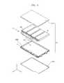
- FIG. 1 is an exploded perspective view of a battery pack according to an embodiment of the present invention
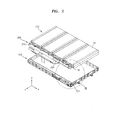
- FIG. 2 is an exploded perspective view illustrating a coupling status of the battery pack of FIG. 1 ;
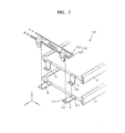
- FIG. 3 is a magnified exploded perspective view of a portion III of FIG. 2 ;
- FIG. 4 is a perspective view illustrating a connection status between unit cells and a lead member in the battery pack of FIG. 1 ;
- FIG. 5 is an exploded perspective view illustrating a connection status of FIG. 4 ;
- FIG. 6 illustrates a side structure of FIG. 5 ;
- FIG. 7 is a perspective view illustrating connection between unit cells and a lead member according to another embodiment of the present invention.
- FIG. 8 illustrates connection between unit cells and a lead member according to another embodiment of the present invention.
- FIG. 9 illustrates connection between unit cells and a lead member according to another embodiment of the present invention.
- FIG. 10 illustrates connection between unit cells and a lead member according to another embodiment of the present invention.
- FIG. 11 is an exploded perspective view illustrating a connection status of FIG. 10 ;
- FIG. 12 illustrates a side structure of FIG. 10 .
- FIG. 1 is an exploded perspective view of a battery pack according to an embodiment of the present invention.
- the battery pack includes a core pack 100, a protective circuit module 200, a frame 300, and a cover 400.
- the core pack 100 may include unit cells 10 capable of being charged and discharged.
- the core pack 100 may be a cell stack body formed by stacking two or more of the unit cells 10 and electrically connecting the unit cells 10.
- the adjacent unit cells 10 make a parallel connection
- the adjacent unit cells 10 make a serial connection.
- Each of the unit cells 10 may have a rectangular shape, and the unit cells 10 may be stacked so that adjacent surfaces of the unit cells 10 may contact each other.
- the protective circuit module 200 may be electrically connected to the core pack 100.
- the protective circuit module 200 may prevent overheat and explosion that may be incurred due to overcharge, overdischarge or overcurrent.
- the protective circuit module 200 may include a circuit board 210 disposed at a side of the core pack 100, and a circuit device 220 mounted on the circuit board 210.
- the circuit device 220 may include a passive device such as a resistor and a condenser or may include an active device such as a field-effect transistor (FET).
- FET field-effect transistor
- the frame 300 may house the core pack 100 and the protective circuit module 200.
- the frame 300 houses the core pack 100 and the protective circuit module 200, and has a structure to be coupled with the cover 400.
- the frame 300 may have a rectangular frame shape.
- the cover 400 may house the core pack 100 and may be coupled with the frame 300. As illustrated in FIG. 1 , the cover 400 may include a top cover 400A and a bottom cover 400B. In other embodiments, the cover 400 may not be separated into top and bottom units but may be formed as one body. The cover 400 may be formed as a thin plate shape.
- an insulating tape (not shown) may be disposed between the cover 400 and the core pack 100.
- the insulating tape may function to insulate the cover 400 including a metal from the core pack 100.
- the insulating tape may also insulate the cover 400 from the protective circuit module 200.
- the top and bottom covers 400A and 400B are assembled with respect to the frame 300 housing the core pack 100 and the protective circuit module 200. That is, the top and bottom covers 400A and 400B are assembled to the frame 300 by having the core pack 100 and the protective circuit module 200 interposed therebetween, and in this regard, the top and bottom covers 400A and 400B, and the frame 300 are coupled by using an appropriate coupling member (not shown). For example, a plurality of coupling holes are formed in the top and bottom covers 400A and 400B, and screw members (not shown) are coupled in the coupling holes via the frame 300, so that coupling may be achieved.
- FIG. 2 is an exploded perspective view illustrating a coupling status of the core pack 100, the protective circuit module 200, and the frame 300 of FIG. 1 .
- FIG. 3 is a magnified exploded perspective view of a portion III of FIG. 2 .
- the core pack 100 and the protective circuit module 200 may be electrically connected by using lead members 150. Ends of the lead members 150 may be connected to the core pack 100 and the other ends of the lead members 150 may be connected to the protective circuit module 200. For example, the ends of the lead members 150 may be connected to electrode tabs (not shown) extending from the unit cells 10 configuring the core pack 100. The other ends of the lead members 150 may be connected to the circuit board 210 configuring the protective circuit module 200.
- the frame 300 may have a partition wall 301 for dividing a first space 300A for housing the core pack 100, and a second space 300B for housing the protective circuit module 200.
- FIG. 4 is a perspective view illustrating a connection status between the core pack 100 and the lead member 150.
- FIG. 5 is an exploded perspective view illustrating a connection status of FIG. 4 .
- FIG. 6 illustrates a side structure of FIG. 5 .
- the core pack 100 includes the unit cells 10 that are vertically stacked.
- a first electrode tab 11a of the first unit cell 11, and a second electrode tab 12a of the second unit cell 12 may form a mutual contact at a first coupling region P11.
- a first coupling region P11 For example, as illustrated in FIG.
- the first electrode tab 11a of the first unit cell 11 may extend in an extension direction (an X-direction), and the second electrode tab 12a of the second unit cell 12 is perpendicularly bent with respect to the extension direction (the X-direction) while extending in a vertical direction (a Z-direction) toward the first electrode tab 11a, and is bent again at an area contacting the first electrode tab 11a and then is coupled while overlapping the first electrode tab 11a.
- the first electrode tab 11a and the second electrode tab 12a may be welded and coupled with each other.
- the first electrode tab 11a and the second electrode tab 12a may be coupled with each other by performing resistance welding.
- the first coupling region P11 may include a contact point between the first electrode tab 11a and the second electrode tab 12a.
- the first coupling region P11 may increase a connection strength of the first and second electrode tabs 11a and 12a and may maintain a firm connection status by connecting the first electrode tab 11a and the second electrode tab 12a.
- coupled members corresponding to the first and second electrode tabs 11a and 12a
- coupled members that are to be coupled in one contact point are limited to only the first and second electrode tabs 11a and 12a, so that a sufficient connection strength may be obtained by performing a welding process once.
- the first and second electrode tabs 11a and 12a are connected in the first coupling region P11, and the first electrode tab 11a and the lead member 150 are connected in a second coupling region P12 formed in another place.
- a connection strength is increased in a manner that the first and second electrode tabs 11a and 12a, and the lead member 150 are not connected in one contact point but connected in contact points that are the first and second coupling regions P11 and P12 at different places.
- a plurality of coupled members corresponding to the first and second electrode tabs 11a and 12a, and the lead member 150
- heat adhesion therebetween is not sufficient, such that a connection strength is weak, and a connection status may be unstable.
- the first unit cell 11 and the second unit cell 12 may have a standardized size in some embodiments, and the first electrode tab 11a and the second electrode tab 12a may have the same longitudinal length.
- the first electrode tab 11a extends in the extension direction (the X-direcfiion) whereas the second electrode tab 12a includes a portion extending in the vertical direction (the Z-direction), so that, compared to the second electrode tab 12a, the first electrode tab 11a further extends from the first coupling region P11, and an end of the second electrode tab 12a is positioned on the first electrode tab 11a.
- the second coupling region P12 is formed on the first electrode tab 11a solely extending from the end of the second electrode tab 12a.
- the second coupling region P12 includes a contact point between the lead member 150 and the first electrode tab 11a.
- the lead member 150 electrically connects the first electrode tab 11a and the protective circuit module 200, and for example, the lead member 150 may include a flexible circuit board such as a flexible printed circuit board (FPCB) and the like.
- FPCB flexible printed circuit board
- the second coupling region P12 may be formed along the extension direction (the X-direction) of the coupled first and second electrode tabs 11a and 12a in a place different from the first coupling region P11 and may be formed in a place separate from the first coupling region P11, that is, the second coupling region P12 may be formed on a region in which the first electrode tab 11a solely extends.
- first and second electrode tabs 11a and 12a, and the lead member 150 are not connected by using one integrated contact point but are connected in separate contact points that are the first coupling region P11 between the first electrode tab 11a and the second electrode tab 12a, and the second coupling region P12 between the first electrode tab 11a and the lead member 150, so that it is possible to limit the number of coupled members (corresponding to the first and second electrode tabs 11a and 12a, and the lead member 150) per one welding process, whereby a coupling strength may be achieved via sufficient heat adhesion.
- a welding electrode (not shown) may be disposed by having the coupled first and second electrode tabs 11a and 12a disposed therebetween, the welding electrode may contact the coupled first and second electrode tabs 11a and 12a, and then the resistance welding may be performed by applying a welding current thereto.
- a welding electrode (not shown) may be disposed by having the first electrode tab 11a and the lead member 150 disposed therebetween, the welding electrode may contact coupled materials (the first electrode tab 11a and the lead member 150), and then the resistance welding may be performed by applying a welding current thereto.
- the first and second coupling regions P11 and P12 may be formed at different times. For example, while a welding electrode (not shown) moves along the extension direction (the X-direction) of the coupled first and second electrode tabs 11a and 12a, welding processes may be performed at temporally different times, so that the first coupling region P11 and the second coupling region P12 may be formed.
- first and second coupling regions P11 and P12 may be simultaneously formed.
- a plurality of welding electrodes (not shown) that are arrayed on a first position and a second position may be driven by performing a welding process once, so that the first and second coupling regions P11 and P12 may be simultaneously formed.
- the first and second unit cells 11 and 12 may have electrode tabs 11aa, 11ab, 12aa, and 12ab having different polarities so as to externally output accumulated power.
- each of the first and second unit cells 11 and 12 may have one of positive electrode tabs 11aa and 12aa and one of negative electrode tabs 11ab and 12ab, respectively.
- the first electrode tab 11a of the first unit cell 11 includes all of the positive electrode tab 11aa and the negative electrode tab 11ab, and the first electrode tab 11a may indicate the positive electrode tab 11aa or the negative electrode tab 11ab.
- the second electrode tab 12a of the second unit cell 12 includes all of the positive electrode tab 12aa and the negative electrode tab 12ab, and the second electrode tab 12a may indicate the positive electrode tab 12aa or the negative electrode tab 12ab.
- the positive electrode tab 11aa of the first unit cell 11, and the positive electrode tab 12aa of the second unit cell 12a may be connected with each other via the first coupling region P11 while the positive electrode tab 11aa of the first unit cell 11 may be electrically connected with the lead member 150 via the second coupling region P12 that is different from the first coupling region P11.
- the negative electrode tab 11ab of the first unit cell 11, and the negative electrode tab 12ab of the second unit cell 12 may be connected with each other via another first coupling region P11 while the negative electrode tab 11ab of the first unit cell 11 may be electrically connected with the lead member 150 via another second coupling region P12 that is different from the other first coupling region P11.
- connection between the first electrode tab 11a of the first unit cell 11 and the second electrode tab 12a of the second unit cell 12 may be only applied to an electrode tab selected from among the positive electrode tab 11aa and the negative electrode tab 11ab of the first unit cell 11, and an electrode tab selected from among the positive electrode tab 12aa and the negative electrode tab 12ab of the second unit cell 12.
- the positive electrode tab 11aa of the first electrode tab 11a of the first unit cell 11, and the negative electrode tab 12ab of the second electrode tab 12a of the second unit cell 12 may be connected to the protective circuit module 200 via the first coupling region P11 and the second coupling region P12.
- the first coupling region P11 and the second coupling region P12 may be alternately disposed to allow the electrode tabs 11aa, 11ab, 12aa, and 12ab having different polarities to be adjacent to each other.
- the lead member 150 that electrically connects the first electrode tab 11a and the protective circuit module 200 may be formed as an FPCB, and may relay power transmission between the first electrode tab 11a and the protective circuit module 200.
- the lead member 150 includes a base film 151 and a wiring unit 155 formed on the base film 151.
- the wiring unit 155 may include a circuit pattern (not shown) extending on the base film 151 toward the protective circuit module 200, and a cover lay (not shown) covering the circuit pattern.
- first electrode tab 11a and the lead member 150 may be achieved in a manner below mentioned. That is, the first electrode tab 11a may extend below a bottom surface of the lead member 150 and may be overlapped with the base film 151. Also, the first electrode tab 11a and the lead member 150 that are overlapped with each other are held between welding electrodes (not shown), and a welding current is applied thereto, so that the resistance welding may be performed on the first electrode tab 11a and the lead member 150.
- the first electrode tab 11a may extend above the lead member 150 and may be arranged on the wiring unit 155 of the lead member 150. Afterward, the first electrode tab 11a and the lead member 150 that are overlapped with each other are held between welding electrodes (not shown), and then the resistance welding may be performed thereon.
- the lead member may comprise a wiring unit and a base film, wherein the base film is arranged between the first electrode tab and the wiring unit at the second coupling region.
- FIGs. 1-6 show a battery pack that includes a core pack 100, a protective circuit module 200, and a lead member 150.
- the core pack 100 includes a plurality of unit cells, including a first cell 11 and a second cell 12.
- the lead member 150 electrically connects electrode tabs of the first and second cells to the protective circuit module 200.
- an electrode tab 11a of the first cell 11 is fixed to an electrode tab 12a of the second cell 12 at a first coupling region P11
- the lead member 150 is fixed to a portion of the electrode tab 11a of the first cell 11 at a second coupling region P12.
- connection strength is increased in a manner that the first and second electrode tabs 11a and 12a, and the lead member 150 are not connected in one contact point but connected in contact points that are the first and second coupling regions P11 and P12 at different places.
- such embodiments provide a battery pack comprising: a first battery cell comprising a first electrode tab; a second battery cell comprising a second electrode tab; a lead member electrically connected to the first electrode tab and the second electrode tab; wherein the first electrode tab and the second electrode tab are coupled together at a first coupling region, and the lead member is coupled to the first electrode tab at a second coupling region, the second coupling region being different to the first coupling region.
- the lead member may be electrically connected to the second electrode tab via the first electrode tab.
- Such embodiments may include a protective circuit module for controlling charge and discharge of the first battery cell and the second battery cell, wherein the lead member is for electrically connecting the first battery cell and the second battery cell to the protective circuit module.
- the second battery cell may be stacked on the first battery cell, and the first electrode tab and the second electrode tab may project in a first direction.
- the first electrode tab has a connection portion that extends in the first direction, wherein a region of the connection portion overlaps with the lead member to form the second coupling region; and the second electrode tab has a first portion extending towards the first electrode tab, and a second portion that overlaps with a region of the connection portion of the first electrode tab to form the first coupling region.
- the second electrode tab has, in some embodiments, a third portion arranged between the first portion of the second electrode tab and the second battery cell, wherein the third portion extends in the first direction.
- FIG. 7 is an exploded perspective view illustrating connection between a core pack 110 and a lead member 150 according to another embodiment of the present invention.
- the core pack 110 may include first and second unit cells 11' and 12', and the first and second unit cells 11' and 12' may include first and second electrode tabs 11a' and 12a', respectively.
- the second electrode tab 12a' may have a notch part N for convenience of a bending work.
- the notch part N defines a bend position of the second electrode tab12a' and allows the second electrode tab 12a' to be consistently bent at the defined bend position.
- the notch part N may have a wedge-shape formed at side ends of a widthwise direction crossing a length of the second electrode tab 12a', and the second electrode tab 12a' may be easily bent in the notch part N according to a decrease in a line width.
- the first unit cell 11' and the second unit cell 12' may have the substantially same structure, and in this case, notch parts M and N may be formed in the first unit cell 11' and the second unit cell 12'.
- FIG. 8 illustrates connection between a core pack 120 and a lead member 150 according to another embodiment of the present invention.
- a first unit cell 11 and a second unit cell 12 are stacked in a vertical direction (a Z-direction), and a first electrode tab 11a of the first unit cell 11 and a second electrode tab 12a of the second unit cell 12 are coupled with each other in a first coupling region P11 so that they are electrically connected.
- the first electrode tab 11a of the first unit cell 11, and the lead member 150 are coupled with each other in a second coupling region P12 that is separate from the first coupling region P11.
- the second electrode tab 12a extends in the vertical direction (the Z-direction) from a main body of the second unit cell 12, and is overlapped on the first electrode tab 11a.
- a supporting member 15 may be interposed between the second electrode tab 12a and the main body of the second unit cell 12 so as to support the second electrode tab 12a.
- the second electrode tab 12a extends in the vertical direction (the Z-direction) while being supported by the supporting member 15, so that the second electrode tab 12a may have a structural stability without unstably suspending in a space, and workability and a handling property in an assembling process including a welding operation for electrical connection may be improved.
- FIG. 9 illustrates connection between a core pack 120 and a lead member 150 according to another embodiment of the present invention.
- a first unit cell 11 and a second unit cell 12 are stacked in a vertical direction (a Z-direction), and a first electrode tab 11a of the first unit cell 11 and a second electrode tab 12a of the second unit cell 12 are coupled with each other in a first coupling region P11 so that the first unit cell 11 and the second unit cell 12 are electrically connected.
- the first electrode tab 11a extends in an extension direction (an X-direction) of the first electrode tab 11a, and the second electrode tab 12a is perpendicularly bent with respect to the extension direction (the X-direction) while extending toward the first electrode tab 11a, is bent again and then is overlapped on the first electrode tab 11a.
- the second electrode tab 12a may have a step shape according to a bending process and a supporting member 15' may be arranged in a lower portion of the second electrode tab 12a so as to stably support the step shape.
- the supporting member 15' is interposed between the second electrode tab 12a and the first electrode tab 11a, and functions to reinforce structural rigidity of the second electrode tab 12a by supporting a height step of the second electrode tab 12a.
- a form or a position of the supporting member 15' is not limited thereto if only the supporting member 15' supports a bent shape or the step shape of the second electrode tab 12a.
- the supporting member 15' may be formed as a form tape but is not limited thereto and thus may be formed by using one of various materials and having one of various shapes.
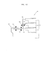
- FIG. 10 illustrates connection between a core pack 130 and a lead member 150 according to another embodiment of the present invention.
- FIG. 11 is an exploded perspective view of a connection structure of FIG. 10 .
- FIG. 12 illustrates a side structure of FIG. 10 .
- the core pack 130 includes a plurality of unit cells 20, for example, the core pack 130 may include three unit cells 21, 22, and 23 that are adjacent to each other, and the three unit cells 21, 22, and 23 may be stacked in a vertical direction (a Z-direction).
- first through third unit cells 21, 22, and 23 are sequentially connected in the unit of a pair via first and second coupling regions P21 and P22 that are different from each other.
- first and second electrode tabs 21a and 22a that extend from the first and second unit cells 21 and 22 are connected to each other in the first coupling region P21
- the second electrode tab 22a and a third electrode tab 23a that extend from the second and third unit cells 22 and 23 are connected to each other in the second coupling region P22.
- the first and second coupling regions P21 and P22 are formed in different places.
- the electrode tabs 21a, 22a, and 23a By limiting the number of the electrode tabs 21a, 22a, and 23a connected via each of the first and second coupling regions P21 and P22, for example, by limiting the number of the electrode tabs 21a, 22a, and 23a as two coupled members per each of the first and second coupling regions P21 and P22, the electrode tabs 21a, 22a, and 23a that are overlapped with each other via sufficient heat adhesion may be connected while having a sufficient coupling strength.
- heat adhesion may not be sufficient in a thickness direction of the first through third electrode tables 21a, 22a, and 23a that are overlapped with each other, such that a coupling strength may become weak, and an unstable connection may be made.
- the first electrode tab 21a extends in an extension direction (an X-direction) of the first electrode tab 21a
- the second electrode tab 22a is perpendicularly bent with respect to the extension direction (the X-direction) while extending in a vertical direction (a Z-direction) toward the first electrode tab 21a, is bent again and then is overlapped on the first electrode tab 21a.
- the third electrode tab 23a is coupled and extends together with the second electrode tab 22a that is perpendicularly bent with respect to the extension direction (the X-direction) while extending in the vertical direction (the Z-direction).
- the first through third unit cells 21, 22, and 23 may have a standardized same specification, so that the first through third electrode tabs 21a, 22a, and 23a may have the same longitudinal length.
- the first electrode tab 21a extends in the extension direction (the X-direction) whereas the second electrode tab 22a extends from an offset position in the vertical direction (the Z-direction), so that the first electrode tab 21a further extends than the second electrode tab 22a in an extension direction (the X-direction) of the coupled first and second electrode tabs 21a and 22a.
- the third electrode tab 23a further extends from an offset position in the vertical direction (the Z-direction) than the second electrode tab 22a, so that the second electrode tab 22a further extends than the third electrode tab 23a in an extension direction (the Z-direction) of the coupled second and third electrode tabs 22a and 23a.
- the first coupling region P21 between the first and second electrode tables 21a and 22a may be formed in a predetermined place on the first electrode tab 21a, and may be formed in a place overlapped with the second electrode tab 22a on the first electrode tab 21a.
- the second coupling region P22 between the second and third electrode tabs 22a and 23a may be formed in a predetermined position on the second electrode tab 22a extending in the vertical direction (the Z-direction).
- the first and second coupling regions P21 and P22 are formed at separate places, and the second electrode tab 22a forms a contact point with the first electrode tab 21a in the first coupling region P21 and simultaneously, the second electrode tab 22a forms another contact point with the third electrode tab 23a in the second coupling region P22.
- the first electrode tab 21a is electrically connected with the lead member 150 via a third coupling region P23. That is, the first electrode tab 21a extends in the extension direction (the X-direction), so that the first electrode tab 21a may further extend than the second and third electrode tabs 22a and 23a extending from an offset position in the vertical direction (the Z-direction), and the first electrode tab 21a may be connected with the lead member 150 via the third coupling region P23 on the first electrode tab 21a solely extending in the extension direction (the X-direction). As illustrated in FIG. 12 , the lead member 150 is overlapped on the first electrode tab 21a, and the third coupling region P23 may be formed by performing welding. Alternatively, the lead member 150 may be overlapped below the first electrode tab 21a, and the third coupling region P23 may be formed by performing welding.
- connection between the first through third electrode tabs 21a, 22a, and 23a may be applied to electrode tabs selected from among electrode tabs 21aa, 21ab, 22aa, 22ab, 23aa and 23ab of the first through third unit cells 21, 22, and 23 or may be applied to all of the electrode tabs 21aa, 21ab, 22aa, 22ab, 23aa and 23ab.
- the first through third unit cells 21, 22, and 23 may include the positive electrode tabs 21aa, 22aa, 23aa and the negative electrode tabs 21ab, 22ab, 23ab which have opposite polarities, and the positive electrode tab 21aa of the first unit cell 21, the positive electrode tab 22aa of the second unit cell 22, and the positive electrode tab 23aa of the third unit cell 23 may sequentially form a pair, may be integrally coupled via the first and second coupling regions P21 and P22, and may be electrically connected with the lead member 150 via the third coupling region P23.
- the negative electrode tab 21ab of the first unit cell 21, the negative electrode tab 22ab of the second unit cell 22, and the negative electrode tab 23ab of the third unit cell 23 may sequentially form a pair, may be coupled to each other via another first coupling region P21 and another second coupling region P22, and may be electrically connected with the lead member 150 via another third coupling region P23.
- the opposite polarities of the first through third unit cells 21, 22, and 23 may be connected with each other.
- the positive electrode tab 21aa of the first unit cell 21 and the negative electrode tab 22ab of the second unit cell 22 may be electrically connected with each other via the first coupling region P21
- the positive electrode tab 22aa of the second unit cell 22 and the negative electrode tab 23ab of the third unit cell 23 may be electrically connected with each other via the second coupling region P22.
- the first through third unit cells 21, 22, and 23 may be connected in series.
- electrode tabs that are connected to an external source for example, the negative electrode tab 21ab of the first unit cell 21 and the positive electrode tab 23aa of the third unit cell 23 may be electrically connected with the lead member 150 via different third coupling regions P23.
- FIGs. 10-12 show embodiments in which there are three unit cells in a vertical stack.
- a first cell 21 has an electrode tab 21a that is fixed to the lead member 150 at a coupling region P23.
- the electrode tab 22a of the second cell 22 is coupled to the electrode tab 21a of the first cell 21 at a coupling region P21, and the electrode tab 23a of the third cell 23 is coupled to the electrode tab 22a of the second cell 22 at a coupling region P22. Therefore, FIG. 12 shows that separate coupling regions P21, P22 and P23 are formed, so as to increase connection strength.
- a battery pack comprising: a first battery cell comprising a first electrode tab, a second battery cell comprising a second electrode tab, and a third battery cell comprising a third electrode tab.
- the first electrode tab and the second electrode tab are coupled together at a coupling region
- the second electrode tab and the third electrode tab are coupled together at a different coupling region.
- a lead member can be electrically connected to the first electrode tab and the second electrode tab at a further different coupling region.
Priority Applications (1)
| Application Number | Priority Date | Filing Date | Title |
|---|---|---|---|
| KR1020120020395A KR101893960B1 (ko) | 2011-03-09 | 2012-02-28 | 배터리 팩 |
Applications Claiming Priority (2)
| Application Number | Priority Date | Filing Date | Title |
|---|---|---|---|
| US201161451050P | 2011-03-09 | 2011-03-09 | |
| US13/244,028 US8741471B2 (en) | 2011-03-09 | 2011-09-23 | Battery pack |
Publications (2)
| Publication Number | Publication Date |
|---|---|
| EP2498321A1 true EP2498321A1 (de) | 2012-09-12 |
| EP2498321B1 EP2498321B1 (de) | 2015-09-30 |
Family
ID=45463453
Family Applications (1)
| Application Number | Title | Priority Date | Filing Date |
|---|---|---|---|
| EP12150360.1A Active EP2498321B1 (de) | 2011-03-09 | 2012-01-06 | Batteriepack |
Country Status (5)
| Country | Link |
|---|---|
| US (1) | US8741471B2 (de) |
| EP (1) | EP2498321B1 (de) |
| JP (1) | JP5957244B2 (de) |
| KR (1) | KR101893960B1 (de) |
| CN (1) | CN102683633B (de) |
Cited By (2)
| Publication number | Priority date | Publication date | Assignee | Title |
|---|---|---|---|---|
| DE102013221139A1 (de) * | 2013-10-17 | 2015-04-23 | Volkswagen Aktiengesellschaft | Batterie mit einer Mehrzahl von Batteriezellen |
| EP2760064A3 (de) * | 2013-01-29 | 2017-02-01 | Samsung SDI Co., Ltd. | Batteriepack |
Families Citing this family (21)
| Publication number | Priority date | Publication date | Assignee | Title |
|---|---|---|---|---|
| KR20120023263A (ko) * | 2010-09-01 | 2012-03-13 | 에스케이이노베이션 주식회사 | 저항 용접에 의한 셀 탭 연결 구조를 가지는 배터리 |
| PL2720301T3 (pl) * | 2011-07-13 | 2019-10-31 | Lg Chemical Ltd | Moduł baterii o zwiększonej niezawodności połączenia oraz zawierający go pakiet baterii o średnim i dużym rozmiarze |
| JP2013105699A (ja) * | 2011-11-16 | 2013-05-30 | Yazaki Corp | 電源装置 |
| KR101408047B1 (ko) * | 2012-11-27 | 2014-06-17 | 삼성에스디아이 주식회사 | 이차 전지 및 이를 포함하는 이차 전지 팩 |
| KR20140129401A (ko) * | 2013-04-18 | 2014-11-07 | 에스케이이노베이션 주식회사 | 배터리 모듈 |
| KR101483130B1 (ko) * | 2013-07-09 | 2015-01-16 | 삼성에스디아이 주식회사 | 전지 팩 |
| CN104282870B (zh) * | 2013-07-09 | 2019-11-12 | 三星Sdi株式会社 | 电池组 |
| US10396334B2 (en) | 2014-03-31 | 2019-08-27 | Lg Chem, Ltd. | Battery module and battery pack comprising same |
| KR102262685B1 (ko) * | 2014-04-29 | 2021-06-08 | 에스케이이노베이션 주식회사 | 배터리 장치 |
| WO2016004079A1 (en) | 2014-06-30 | 2016-01-07 | Black & Decker Inc. | Battery pack for a cordless power tools |
| KR102256293B1 (ko) * | 2014-07-28 | 2021-05-26 | 삼성에스디아이 주식회사 | 배터리 팩 |
| CN108352489B (zh) * | 2015-10-22 | 2020-06-02 | 远景Aesc日本有限公司 | 组电池及组电池的制造方法 |
| KR102106999B1 (ko) * | 2016-04-25 | 2020-05-06 | 주식회사 엘지화학 | 규격화된 구조에 기반하여 제조 공정성이 우수하면서도 전극리드의 절연 성능이 향상된 전지셀 및 이를 포함하는 전지팩 |
| JP6762156B2 (ja) * | 2016-07-15 | 2020-09-30 | 株式会社エンビジョンAescジャパン | 組電池及び組電池の製造方法 |
| KR102288121B1 (ko) * | 2017-09-07 | 2021-08-11 | 주식회사 엘지에너지솔루션 | 파우치 형 이차 전지 |
| KR102422515B1 (ko) * | 2017-10-19 | 2022-07-19 | 삼성에스디아이 주식회사 | 배터리 팩 |
| KR102130827B1 (ko) | 2017-11-15 | 2020-07-06 | 삼성에스디아이 주식회사 | 배터리 팩 |
| KR102468028B1 (ko) | 2018-05-29 | 2022-11-17 | 주식회사 엘지에너지솔루션 | 배터리 모듈 |
| KR20190138972A (ko) * | 2018-06-07 | 2019-12-17 | 삼성전자주식회사 | 전극 탭들을 구비한 배터리 및 이를 구비한 전자 장치 |
| JP7154875B2 (ja) * | 2018-08-21 | 2022-10-18 | Fdk株式会社 | 蓄電素子 |
| KR102366138B1 (ko) | 2018-12-06 | 2022-02-22 | 주식회사 엘지에너지솔루션 | 전지 모듈 |
Citations (1)
| Publication number | Priority date | Publication date | Assignee | Title |
|---|---|---|---|---|
| US20040050414A1 (en) * | 2002-07-30 | 2004-03-18 | Nissan Motor Co., Ltd. | Module battery |
Family Cites Families (9)
| Publication number | Priority date | Publication date | Assignee | Title |
|---|---|---|---|---|
| KR100516768B1 (ko) * | 2003-08-16 | 2005-09-22 | 삼성에스디아이 주식회사 | 전극탭 병렬결합구조를 갖는 이차전지 및 그 전극탭 결합 방법 |
| JP4873977B2 (ja) * | 2006-03-30 | 2012-02-08 | 三洋電機株式会社 | パック電池 |
| JP2007280617A (ja) * | 2006-04-03 | 2007-10-25 | Sony Corp | 電池パック |
| KR100893225B1 (ko) | 2006-07-24 | 2009-04-16 | 주식회사 엘지화학 | 용량 및 안전성을 향상시킨 이차전지 |
| JP4165586B2 (ja) * | 2006-08-02 | 2008-10-15 | ソニー株式会社 | 電池パック |
| JP5354846B2 (ja) | 2006-08-11 | 2013-11-27 | 株式会社東芝 | 組電池および組電池の充放電方法 |
| KR100900412B1 (ko) | 2006-08-14 | 2009-06-01 | 주식회사 엘지화학 | 향상된 안전성과 콤팩트한 구조의 이차전지 |
| KR20100063378A (ko) | 2008-12-03 | 2010-06-11 | 삼성에스디아이 주식회사 | 배터리팩 |
| JP5509684B2 (ja) | 2009-06-03 | 2014-06-04 | ソニー株式会社 | 電池パック |
-
2011
- 2011-09-23 US US13/244,028 patent/US8741471B2/en active Active
-
2012
- 2012-01-06 EP EP12150360.1A patent/EP2498321B1/de active Active
- 2012-02-24 CN CN201210046133.3A patent/CN102683633B/zh active Active
- 2012-02-28 KR KR1020120020395A patent/KR101893960B1/ko active IP Right Grant
- 2012-03-05 JP JP2012048191A patent/JP5957244B2/ja active Active
Patent Citations (1)
| Publication number | Priority date | Publication date | Assignee | Title |
|---|---|---|---|---|
| US20040050414A1 (en) * | 2002-07-30 | 2004-03-18 | Nissan Motor Co., Ltd. | Module battery |
Cited By (3)
| Publication number | Priority date | Publication date | Assignee | Title |
|---|---|---|---|---|
| EP2760064A3 (de) * | 2013-01-29 | 2017-02-01 | Samsung SDI Co., Ltd. | Batteriepack |
| DE102013221139A1 (de) * | 2013-10-17 | 2015-04-23 | Volkswagen Aktiengesellschaft | Batterie mit einer Mehrzahl von Batteriezellen |
| DE102013221139B4 (de) | 2013-10-17 | 2021-11-25 | Volkswagen Aktiengesellschaft | Batterie mit einer Mehrzahl von Batteriezellen, welche um einen Rand eines Rahmens umgebogene Ableiterelemente aufweisen |
Also Published As
| Publication number | Publication date |
|---|---|
| KR20130023033A (ko) | 2013-03-07 |
| CN102683633B (zh) | 2017-03-01 |
| EP2498321B1 (de) | 2015-09-30 |
| CN102683633A (zh) | 2012-09-19 |
| US20120231300A1 (en) | 2012-09-13 |
| JP2012190797A (ja) | 2012-10-04 |
| KR101893960B1 (ko) | 2018-08-31 |
| US8741471B2 (en) | 2014-06-03 |
| JP5957244B2 (ja) | 2016-07-27 |
Similar Documents
| Publication | Publication Date | Title |
|---|---|---|
| EP2498321B1 (de) | Batteriepack | |
| CN102376992B (zh) | 电池模块 | |
| CN106486713B (zh) | 电池组 | |
| US8663827B2 (en) | Battery pack | |
| CN106601945B (zh) | 可再充电电池模块 | |
| KR102248597B1 (ko) | 배터리 팩 | |
| US10236485B2 (en) | Battery module | |
| US20150086834A1 (en) | Battery module having holder | |
| US8669004B2 (en) | Battery pack | |
| US20130089755A1 (en) | Battery Pack | |
| KR101440890B1 (ko) | 전지 팩 | |
| JP2014236003A (ja) | バッテリパック | |
| EP2905824A1 (de) | Batteriepack | |
| JP5490027B2 (ja) | 二次電池及びその製造方法 | |
| JP2014512660A (ja) | バッテリーセルのセンシング基板 | |
| US20170141438A1 (en) | Battery pack | |
| JP2016171063A (ja) | バッテリーパック | |
| KR20180015494A (ko) | 배터리 팩 | |
| JP2013214464A (ja) | 電池 | |
| US20100291434A1 (en) | Connector and battery pack having the same | |
| US10079381B2 (en) | Rechargeable battery pack | |
| US20150064504A1 (en) | Battery module having connecting tab | |
| KR101031178B1 (ko) | 슬림형 이차전지 | |
| CN111512467B (zh) | 电池组 | |
| JP2002298805A (ja) | パック電池 |
Legal Events
| Date | Code | Title | Description |
|---|---|---|---|
| PUAI | Public reference made under article 153(3) epc to a published international application that has entered the european phase |
Free format text: ORIGINAL CODE: 0009012 |
|
| 17P | Request for examination filed |
Effective date: 20120329 |
|
| AK | Designated contracting states |
Kind code of ref document: A1 Designated state(s): AL AT BE BG CH CY CZ DE DK EE ES FI FR GB GR HR HU IE IS IT LI LT LU LV MC MK MT NL NO PL PT RO RS SE SI SK SM TR |
|
| AX | Request for extension of the european patent |
Extension state: BA ME |
|
| 17Q | First examination report despatched |
Effective date: 20131218 |
|
| RIC1 | Information provided on ipc code assigned before grant |
Ipc: H01M 2/26 20060101ALI20150310BHEP Ipc: H01M 2/20 20060101AFI20150310BHEP Ipc: H01M 10/42 20060101ALN20150310BHEP |
|
| GRAP | Despatch of communication of intention to grant a patent |
Free format text: ORIGINAL CODE: EPIDOSNIGR1 |
|
| INTG | Intention to grant announced |
Effective date: 20150417 |
|
| RAP1 | Party data changed (applicant data changed or rights of an application transferred) |
Owner name: SAMSUNG SDI CO., LTD |
|
| GRAS | Grant fee paid |
Free format text: ORIGINAL CODE: EPIDOSNIGR3 |
|
| GRAA | (expected) grant |
Free format text: ORIGINAL CODE: 0009210 |
|
| AK | Designated contracting states |
Kind code of ref document: B1 Designated state(s): AL AT BE BG CH CY CZ DE DK EE ES FI FR GB GR HR HU IE IS IT LI LT LU LV MC MK MT NL NO PL PT RO RS SE SI SK SM TR |
|
| REG | Reference to a national code |
Ref country code: CH Ref legal event code: EP Ref country code: GB Ref legal event code: FG4D |
|
| REG | Reference to a national code |
Ref country code: AT Ref legal event code: REF Ref document number: 752902 Country of ref document: AT Kind code of ref document: T Effective date: 20151015 |
|
| REG | Reference to a national code |
Ref country code: IE Ref legal event code: FG4D |
|
| REG | Reference to a national code |
Ref country code: DE Ref legal event code: R096 Ref document number: 602012011042 Country of ref document: DE |
|
| REG | Reference to a national code |
Ref country code: FR Ref legal event code: PLFP Year of fee payment: 5 |
|
| PG25 | Lapsed in a contracting state [announced via postgrant information from national office to epo] |
Ref country code: LV Free format text: LAPSE BECAUSE OF FAILURE TO SUBMIT A TRANSLATION OF THE DESCRIPTION OR TO PAY THE FEE WITHIN THE PRESCRIBED TIME-LIMIT Effective date: 20150930 Ref country code: GR Free format text: LAPSE BECAUSE OF FAILURE TO SUBMIT A TRANSLATION OF THE DESCRIPTION OR TO PAY THE FEE WITHIN THE PRESCRIBED TIME-LIMIT Effective date: 20151231 Ref country code: NO Free format text: LAPSE BECAUSE OF FAILURE TO SUBMIT A TRANSLATION OF THE DESCRIPTION OR TO PAY THE FEE WITHIN THE PRESCRIBED TIME-LIMIT Effective date: 20151230 Ref country code: LT Free format text: LAPSE BECAUSE OF FAILURE TO SUBMIT A TRANSLATION OF THE DESCRIPTION OR TO PAY THE FEE WITHIN THE PRESCRIBED TIME-LIMIT Effective date: 20150930 Ref country code: FI Free format text: LAPSE BECAUSE OF FAILURE TO SUBMIT A TRANSLATION OF THE DESCRIPTION OR TO PAY THE FEE WITHIN THE PRESCRIBED TIME-LIMIT Effective date: 20150930 |
|
| REG | Reference to a national code |
Ref country code: NL Ref legal event code: MP Effective date: 20150930 |
|
| REG | Reference to a national code |
Ref country code: LT Ref legal event code: MG4D |
|
| REG | Reference to a national code |
Ref country code: AT Ref legal event code: MK05 Ref document number: 752902 Country of ref document: AT Kind code of ref document: T Effective date: 20150930 |
|
| PG25 | Lapsed in a contracting state [announced via postgrant information from national office to epo] |
Ref country code: SE Free format text: LAPSE BECAUSE OF FAILURE TO SUBMIT A TRANSLATION OF THE DESCRIPTION OR TO PAY THE FEE WITHIN THE PRESCRIBED TIME-LIMIT Effective date: 20150930 Ref country code: RS Free format text: LAPSE BECAUSE OF FAILURE TO SUBMIT A TRANSLATION OF THE DESCRIPTION OR TO PAY THE FEE WITHIN THE PRESCRIBED TIME-LIMIT Effective date: 20150930 Ref country code: HR Free format text: LAPSE BECAUSE OF FAILURE TO SUBMIT A TRANSLATION OF THE DESCRIPTION OR TO PAY THE FEE WITHIN THE PRESCRIBED TIME-LIMIT Effective date: 20150930 |
|
| PG25 | Lapsed in a contracting state [announced via postgrant information from national office to epo] |
Ref country code: IS Free format text: LAPSE BECAUSE OF FAILURE TO SUBMIT A TRANSLATION OF THE DESCRIPTION OR TO PAY THE FEE WITHIN THE PRESCRIBED TIME-LIMIT Effective date: 20160130 Ref country code: EE Free format text: LAPSE BECAUSE OF FAILURE TO SUBMIT A TRANSLATION OF THE DESCRIPTION OR TO PAY THE FEE WITHIN THE PRESCRIBED TIME-LIMIT Effective date: 20150930 Ref country code: ES Free format text: LAPSE BECAUSE OF FAILURE TO SUBMIT A TRANSLATION OF THE DESCRIPTION OR TO PAY THE FEE WITHIN THE PRESCRIBED TIME-LIMIT Effective date: 20150930 Ref country code: SK Free format text: LAPSE BECAUSE OF FAILURE TO SUBMIT A TRANSLATION OF THE DESCRIPTION OR TO PAY THE FEE WITHIN THE PRESCRIBED TIME-LIMIT Effective date: 20150930 Ref country code: CZ Free format text: LAPSE BECAUSE OF FAILURE TO SUBMIT A TRANSLATION OF THE DESCRIPTION OR TO PAY THE FEE WITHIN THE PRESCRIBED TIME-LIMIT Effective date: 20150930 Ref country code: NL Free format text: LAPSE BECAUSE OF FAILURE TO SUBMIT A TRANSLATION OF THE DESCRIPTION OR TO PAY THE FEE WITHIN THE PRESCRIBED TIME-LIMIT Effective date: 20150930 Ref country code: IT Free format text: LAPSE BECAUSE OF FAILURE TO SUBMIT A TRANSLATION OF THE DESCRIPTION OR TO PAY THE FEE WITHIN THE PRESCRIBED TIME-LIMIT Effective date: 20150930 |
|
| PG25 | Lapsed in a contracting state [announced via postgrant information from national office to epo] |
Ref country code: BE Free format text: LAPSE BECAUSE OF NON-PAYMENT OF DUE FEES Effective date: 20160131 Ref country code: PL Free format text: LAPSE BECAUSE OF FAILURE TO SUBMIT A TRANSLATION OF THE DESCRIPTION OR TO PAY THE FEE WITHIN THE PRESCRIBED TIME-LIMIT Effective date: 20150930 Ref country code: RO Free format text: LAPSE BECAUSE OF FAILURE TO SUBMIT A TRANSLATION OF THE DESCRIPTION OR TO PAY THE FEE WITHIN THE PRESCRIBED TIME-LIMIT Effective date: 20150930 Ref country code: PT Free format text: LAPSE BECAUSE OF FAILURE TO SUBMIT A TRANSLATION OF THE DESCRIPTION OR TO PAY THE FEE WITHIN THE PRESCRIBED TIME-LIMIT Effective date: 20160201 Ref country code: AT Free format text: LAPSE BECAUSE OF FAILURE TO SUBMIT A TRANSLATION OF THE DESCRIPTION OR TO PAY THE FEE WITHIN THE PRESCRIBED TIME-LIMIT Effective date: 20150930 |
|
| REG | Reference to a national code |
Ref country code: DE Ref legal event code: R097 Ref document number: 602012011042 Country of ref document: DE |
|
| PLBE | No opposition filed within time limit |
Free format text: ORIGINAL CODE: 0009261 |
|
| STAA | Information on the status of an ep patent application or granted ep patent |
Free format text: STATUS: NO OPPOSITION FILED WITHIN TIME LIMIT |
|
| PG25 | Lapsed in a contracting state [announced via postgrant information from national office to epo] |
Ref country code: DK Free format text: LAPSE BECAUSE OF FAILURE TO SUBMIT A TRANSLATION OF THE DESCRIPTION OR TO PAY THE FEE WITHIN THE PRESCRIBED TIME-LIMIT Effective date: 20150930 Ref country code: LU Free format text: LAPSE BECAUSE OF FAILURE TO SUBMIT A TRANSLATION OF THE DESCRIPTION OR TO PAY THE FEE WITHIN THE PRESCRIBED TIME-LIMIT Effective date: 20160106 |
|
| REG | Reference to a national code |
Ref country code: CH Ref legal event code: PL |
|
| 26N | No opposition filed |
Effective date: 20160701 |
|
| PG25 | Lapsed in a contracting state [announced via postgrant information from national office to epo] |
Ref country code: MC Free format text: LAPSE BECAUSE OF FAILURE TO SUBMIT A TRANSLATION OF THE DESCRIPTION OR TO PAY THE FEE WITHIN THE PRESCRIBED TIME-LIMIT Effective date: 20150930 |
|
| PG25 | Lapsed in a contracting state [announced via postgrant information from national office to epo] |
Ref country code: LI Free format text: LAPSE BECAUSE OF NON-PAYMENT OF DUE FEES Effective date: 20160131 Ref country code: CH Free format text: LAPSE BECAUSE OF NON-PAYMENT OF DUE FEES Effective date: 20160131 |
|
| REG | Reference to a national code |
Ref country code: IE Ref legal event code: MM4A |
|
| PG25 | Lapsed in a contracting state [announced via postgrant information from national office to epo] |
Ref country code: SI Free format text: LAPSE BECAUSE OF FAILURE TO SUBMIT A TRANSLATION OF THE DESCRIPTION OR TO PAY THE FEE WITHIN THE PRESCRIBED TIME-LIMIT Effective date: 20150930 |
|
| REG | Reference to a national code |
Ref country code: FR Ref legal event code: PLFP Year of fee payment: 6 |
|
| PG25 | Lapsed in a contracting state [announced via postgrant information from national office to epo] |
Ref country code: BE Free format text: LAPSE BECAUSE OF FAILURE TO SUBMIT A TRANSLATION OF THE DESCRIPTION OR TO PAY THE FEE WITHIN THE PRESCRIBED TIME-LIMIT Effective date: 20150930 |
|
| PG25 | Lapsed in a contracting state [announced via postgrant information from national office to epo] |
Ref country code: IE Free format text: LAPSE BECAUSE OF NON-PAYMENT OF DUE FEES Effective date: 20160106 |
|
| PG25 | Lapsed in a contracting state [announced via postgrant information from national office to epo] |
Ref country code: MT Free format text: LAPSE BECAUSE OF FAILURE TO SUBMIT A TRANSLATION OF THE DESCRIPTION OR TO PAY THE FEE WITHIN THE PRESCRIBED TIME-LIMIT Effective date: 20150930 |
|
| REG | Reference to a national code |
Ref country code: FR Ref legal event code: PLFP Year of fee payment: 7 |
|
| PG25 | Lapsed in a contracting state [announced via postgrant information from national office to epo] |
Ref country code: CY Free format text: LAPSE BECAUSE OF FAILURE TO SUBMIT A TRANSLATION OF THE DESCRIPTION OR TO PAY THE FEE WITHIN THE PRESCRIBED TIME-LIMIT Effective date: 20150930 Ref country code: SM Free format text: LAPSE BECAUSE OF FAILURE TO SUBMIT A TRANSLATION OF THE DESCRIPTION OR TO PAY THE FEE WITHIN THE PRESCRIBED TIME-LIMIT Effective date: 20150930 Ref country code: HU Free format text: LAPSE BECAUSE OF FAILURE TO SUBMIT A TRANSLATION OF THE DESCRIPTION OR TO PAY THE FEE WITHIN THE PRESCRIBED TIME-LIMIT; INVALID AB INITIO Effective date: 20120106 |
|
| PG25 | Lapsed in a contracting state [announced via postgrant information from national office to epo] |
Ref country code: MK Free format text: LAPSE BECAUSE OF FAILURE TO SUBMIT A TRANSLATION OF THE DESCRIPTION OR TO PAY THE FEE WITHIN THE PRESCRIBED TIME-LIMIT Effective date: 20150930 Ref country code: TR Free format text: LAPSE BECAUSE OF FAILURE TO SUBMIT A TRANSLATION OF THE DESCRIPTION OR TO PAY THE FEE WITHIN THE PRESCRIBED TIME-LIMIT Effective date: 20150930 Ref country code: MT Free format text: LAPSE BECAUSE OF FAILURE TO SUBMIT A TRANSLATION OF THE DESCRIPTION OR TO PAY THE FEE WITHIN THE PRESCRIBED TIME-LIMIT Effective date: 20160131 |
|
| PG25 | Lapsed in a contracting state [announced via postgrant information from national office to epo] |
Ref country code: BG Free format text: LAPSE BECAUSE OF FAILURE TO SUBMIT A TRANSLATION OF THE DESCRIPTION OR TO PAY THE FEE WITHIN THE PRESCRIBED TIME-LIMIT Effective date: 20150930 |
|
| PG25 | Lapsed in a contracting state [announced via postgrant information from national office to epo] |
Ref country code: AL Free format text: LAPSE BECAUSE OF FAILURE TO SUBMIT A TRANSLATION OF THE DESCRIPTION OR TO PAY THE FEE WITHIN THE PRESCRIBED TIME-LIMIT Effective date: 20150930 |
|
| REG | Reference to a national code |
Ref country code: DE Ref legal event code: R079 Ref document number: 602012011042 Country of ref document: DE Free format text: PREVIOUS MAIN CLASS: H01M0002200000 Ipc: H01M0050500000 |
|
| PGFP | Annual fee paid to national office [announced via postgrant information from national office to epo] |
Ref country code: DE Payment date: 20221229 Year of fee payment: 12 |
|
| P01 | Opt-out of the competence of the unified patent court (upc) registered |
Effective date: 20230528 |
|
| PGFP | Annual fee paid to national office [announced via postgrant information from national office to epo] |
Ref country code: GB Payment date: 20231221 Year of fee payment: 13 |
|
| PGFP | Annual fee paid to national office [announced via postgrant information from national office to epo] |
Ref country code: FR Payment date: 20231222 Year of fee payment: 13 |
|
| PGFP | Annual fee paid to national office [announced via postgrant information from national office to epo] |
Ref country code: DE Payment date: 20231228 Year of fee payment: 13 |