EP2497145B1 - Energiespeichervorrichtung - Google Patents
Energiespeichervorrichtung Download PDFInfo
- Publication number
- EP2497145B1 EP2497145B1 EP20100779298 EP10779298A EP2497145B1 EP 2497145 B1 EP2497145 B1 EP 2497145B1 EP 20100779298 EP20100779298 EP 20100779298 EP 10779298 A EP10779298 A EP 10779298A EP 2497145 B1 EP2497145 B1 EP 2497145B1
- Authority
- EP
- European Patent Office
- Prior art keywords
- cooling
- energy store
- multiplicity
- electrochemical energy
- energy storage
- Prior art date
- Legal status (The legal status is an assumption and is not a legal conclusion. Google has not performed a legal analysis and makes no representation as to the accuracy of the status listed.)
- Not-in-force
Links
- 238000001816 cooling Methods 0.000 claims description 189
- 239000012809 cooling fluid Substances 0.000 claims description 9
- 239000012212 insulator Substances 0.000 claims description 7
- 239000004020 conductor Substances 0.000 claims description 3
- 230000015572 biosynthetic process Effects 0.000 claims description 2
- 238000005755 formation reaction Methods 0.000 claims 1
- 238000007789 sealing Methods 0.000 claims 1
- 210000004027 cell Anatomy 0.000 description 93
- 238000004146 energy storage Methods 0.000 description 48
- 238000012983 electrochemical energy storage Methods 0.000 description 39
- 230000017525 heat dissipation Effects 0.000 description 9
- 238000004519 manufacturing process Methods 0.000 description 8
- 238000004026 adhesive bonding Methods 0.000 description 7
- 238000013459 approach Methods 0.000 description 6
- 238000011161 development Methods 0.000 description 5
- 239000002826 coolant Substances 0.000 description 4
- 238000001125 extrusion Methods 0.000 description 4
- 238000013461 design Methods 0.000 description 3
- 238000009826 distribution Methods 0.000 description 3
- 238000009413 insulation Methods 0.000 description 3
- 239000000463 material Substances 0.000 description 3
- 238000012856 packing Methods 0.000 description 3
- 238000012546 transfer Methods 0.000 description 3
- 239000000853 adhesive Substances 0.000 description 2
- 230000001070 adhesive effect Effects 0.000 description 2
- 238000005266 casting Methods 0.000 description 2
- 239000002131 composite material Substances 0.000 description 2
- 150000001875 compounds Chemical class 0.000 description 2
- 238000010276 construction Methods 0.000 description 2
- 238000005538 encapsulation Methods 0.000 description 2
- 239000012530 fluid Substances 0.000 description 2
- 238000009434 installation Methods 0.000 description 2
- 238000002955 isolation Methods 0.000 description 2
- 229910001416 lithium ion Inorganic materials 0.000 description 2
- 238000000034 method Methods 0.000 description 2
- 238000004382 potting Methods 0.000 description 2
- 239000011253 protective coating Substances 0.000 description 2
- 239000003507 refrigerant Substances 0.000 description 2
- XLYOFNOQVPJJNP-UHFFFAOYSA-N water Substances O XLYOFNOQVPJJNP-UHFFFAOYSA-N 0.000 description 2
- 210000001015 abdomen Anatomy 0.000 description 1
- 239000012790 adhesive layer Substances 0.000 description 1
- 210000002421 cell wall Anatomy 0.000 description 1
- 239000003795 chemical substances by application Substances 0.000 description 1
- 238000005253 cladding Methods 0.000 description 1
- 238000004891 communication Methods 0.000 description 1
- 230000000694 effects Effects 0.000 description 1
- 238000005304 joining Methods 0.000 description 1
- 239000004922 lacquer Substances 0.000 description 1
- 230000013011 mating Effects 0.000 description 1
- 239000002184 metal Substances 0.000 description 1
- 239000003973 paint Substances 0.000 description 1
- 238000000926 separation method Methods 0.000 description 1
- 238000004088 simulation Methods 0.000 description 1
- 238000005476 soldering Methods 0.000 description 1
- 239000013585 weight reducing agent Substances 0.000 description 1
- 238000003466 welding Methods 0.000 description 1
Images


Classifications
-
- H—ELECTRICITY
- H01—ELECTRIC ELEMENTS
- H01M—PROCESSES OR MEANS, e.g. BATTERIES, FOR THE DIRECT CONVERSION OF CHEMICAL ENERGY INTO ELECTRICAL ENERGY
- H01M10/00—Secondary cells; Manufacture thereof
- H01M10/60—Heating or cooling; Temperature control
- H01M10/61—Types of temperature control
- H01M10/613—Cooling or keeping cold
-
- H—ELECTRICITY
- H01—ELECTRIC ELEMENTS
- H01M—PROCESSES OR MEANS, e.g. BATTERIES, FOR THE DIRECT CONVERSION OF CHEMICAL ENERGY INTO ELECTRICAL ENERGY
- H01M10/00—Secondary cells; Manufacture thereof
- H01M10/60—Heating or cooling; Temperature control
- H01M10/65—Means for temperature control structurally associated with the cells
- H01M10/656—Means for temperature control structurally associated with the cells characterised by the type of heat-exchange fluid
- H01M10/6567—Liquids
- H01M10/6568—Liquids characterised by flow circuits, e.g. loops, located externally to the cells or cell casings
-
- F—MECHANICAL ENGINEERING; LIGHTING; HEATING; WEAPONS; BLASTING
- F25—REFRIGERATION OR COOLING; COMBINED HEATING AND REFRIGERATION SYSTEMS; HEAT PUMP SYSTEMS; MANUFACTURE OR STORAGE OF ICE; LIQUEFACTION SOLIDIFICATION OF GASES
- F25D—REFRIGERATORS; COLD ROOMS; ICE-BOXES; COOLING OR FREEZING APPARATUS NOT OTHERWISE PROVIDED FOR
- F25D17/00—Arrangements for circulating cooling fluids; Arrangements for circulating gas, e.g. air, within refrigerated spaces
- F25D17/04—Arrangements for circulating cooling fluids; Arrangements for circulating gas, e.g. air, within refrigerated spaces for circulating air, e.g. by convection
- F25D17/06—Arrangements for circulating cooling fluids; Arrangements for circulating gas, e.g. air, within refrigerated spaces for circulating air, e.g. by convection by forced circulation
- F25D17/08—Arrangements for circulating cooling fluids; Arrangements for circulating gas, e.g. air, within refrigerated spaces for circulating air, e.g. by convection by forced circulation using ducts
-
- H—ELECTRICITY
- H01—ELECTRIC ELEMENTS
- H01M—PROCESSES OR MEANS, e.g. BATTERIES, FOR THE DIRECT CONVERSION OF CHEMICAL ENERGY INTO ELECTRICAL ENERGY
- H01M10/00—Secondary cells; Manufacture thereof
- H01M10/05—Accumulators with non-aqueous electrolyte
- H01M10/052—Li-accumulators
- H01M10/0525—Rocking-chair batteries, i.e. batteries with lithium insertion or intercalation in both electrodes; Lithium-ion batteries
-
- H—ELECTRICITY
- H01—ELECTRIC ELEMENTS
- H01M—PROCESSES OR MEANS, e.g. BATTERIES, FOR THE DIRECT CONVERSION OF CHEMICAL ENERGY INTO ELECTRICAL ENERGY
- H01M10/00—Secondary cells; Manufacture thereof
- H01M10/60—Heating or cooling; Temperature control
- H01M10/62—Heating or cooling; Temperature control specially adapted for specific applications
- H01M10/625—Vehicles
-
- H—ELECTRICITY
- H01—ELECTRIC ELEMENTS
- H01M—PROCESSES OR MEANS, e.g. BATTERIES, FOR THE DIRECT CONVERSION OF CHEMICAL ENERGY INTO ELECTRICAL ENERGY
- H01M10/00—Secondary cells; Manufacture thereof
- H01M10/60—Heating or cooling; Temperature control
- H01M10/64—Heating or cooling; Temperature control characterised by the shape of the cells
- H01M10/647—Prismatic or flat cells, e.g. pouch cells
-
- H—ELECTRICITY
- H01—ELECTRIC ELEMENTS
- H01M—PROCESSES OR MEANS, e.g. BATTERIES, FOR THE DIRECT CONVERSION OF CHEMICAL ENERGY INTO ELECTRICAL ENERGY
- H01M10/00—Secondary cells; Manufacture thereof
- H01M10/60—Heating or cooling; Temperature control
- H01M10/65—Means for temperature control structurally associated with the cells
- H01M10/655—Solid structures for heat exchange or heat conduction
- H01M10/6556—Solid parts with flow channel passages or pipes for heat exchange
- H01M10/6557—Solid parts with flow channel passages or pipes for heat exchange arranged between the cells
-
- H—ELECTRICITY
- H01—ELECTRIC ELEMENTS
- H01M—PROCESSES OR MEANS, e.g. BATTERIES, FOR THE DIRECT CONVERSION OF CHEMICAL ENERGY INTO ELECTRICAL ENERGY
- H01M10/00—Secondary cells; Manufacture thereof
- H01M10/60—Heating or cooling; Temperature control
- H01M10/65—Means for temperature control structurally associated with the cells
- H01M10/656—Means for temperature control structurally associated with the cells characterised by the type of heat-exchange fluid
- H01M10/6567—Liquids
-
- H—ELECTRICITY
- H01—ELECTRIC ELEMENTS
- H01M—PROCESSES OR MEANS, e.g. BATTERIES, FOR THE DIRECT CONVERSION OF CHEMICAL ENERGY INTO ELECTRICAL ENERGY
- H01M50/00—Constructional details or processes of manufacture of the non-active parts of electrochemical cells other than fuel cells, e.g. hybrid cells
- H01M50/10—Primary casings, jackets or wrappings of a single cell or a single battery
- H01M50/102—Primary casings, jackets or wrappings of a single cell or a single battery characterised by their shape or physical structure
- H01M50/103—Primary casings, jackets or wrappings of a single cell or a single battery characterised by their shape or physical structure prismatic or rectangular
-
- H—ELECTRICITY
- H01—ELECTRIC ELEMENTS
- H01M—PROCESSES OR MEANS, e.g. BATTERIES, FOR THE DIRECT CONVERSION OF CHEMICAL ENERGY INTO ELECTRICAL ENERGY
- H01M10/00—Secondary cells; Manufacture thereof
- H01M10/04—Construction or manufacture in general
- H01M10/0413—Large-sized flat cells or batteries for motive or stationary systems with plate-like electrodes
-
- Y—GENERAL TAGGING OF NEW TECHNOLOGICAL DEVELOPMENTS; GENERAL TAGGING OF CROSS-SECTIONAL TECHNOLOGIES SPANNING OVER SEVERAL SECTIONS OF THE IPC; TECHNICAL SUBJECTS COVERED BY FORMER USPC CROSS-REFERENCE ART COLLECTIONS [XRACs] AND DIGESTS
- Y02—TECHNOLOGIES OR APPLICATIONS FOR MITIGATION OR ADAPTATION AGAINST CLIMATE CHANGE
- Y02E—REDUCTION OF GREENHOUSE GAS [GHG] EMISSIONS, RELATED TO ENERGY GENERATION, TRANSMISSION OR DISTRIBUTION
- Y02E60/00—Enabling technologies; Technologies with a potential or indirect contribution to GHG emissions mitigation
- Y02E60/10—Energy storage using batteries
-
- Y—GENERAL TAGGING OF NEW TECHNOLOGICAL DEVELOPMENTS; GENERAL TAGGING OF CROSS-SECTIONAL TECHNOLOGIES SPANNING OVER SEVERAL SECTIONS OF THE IPC; TECHNICAL SUBJECTS COVERED BY FORMER USPC CROSS-REFERENCE ART COLLECTIONS [XRACs] AND DIGESTS
- Y02—TECHNOLOGIES OR APPLICATIONS FOR MITIGATION OR ADAPTATION AGAINST CLIMATE CHANGE
- Y02P—CLIMATE CHANGE MITIGATION TECHNOLOGIES IN THE PRODUCTION OR PROCESSING OF GOODS
- Y02P70/00—Climate change mitigation technologies in the production process for final industrial or consumer products
- Y02P70/50—Manufacturing or production processes characterised by the final manufactured product
Definitions
- the present invention relates to an energy storage device and a use of a cooling device for cooling a stack of a plurality of electrochemical energy storage units.
- the publication 102007066944.4 describes, inter alia, a cooling of battery flat cells, which shows cooling plates as a thermal path. It is mentioned that the sheets are in thermal contact with the cooling plate; This contact should be made by casting.
- the patent DE 102 23 782 B4 describes a cooling device of round cells, consisting of a base plate and laterally in the longitudinal direction of the cells adjacent cooling elements.
- the cells are frictionally connected to the cooling device, the adjacent cooling elements have expansion joints to improve the problem of gap formation and heat transfer.
- the publication JP 2005 302698 A discloses a battery assembly and a vehicle in which a corresponding battery assembly is provided.
- the battery assembly has eight battery packs, each stack being formed of ten secondary cells. Furthermore, heat sinks are provided, between which the secondary cells are arranged.
- the battery assembly is enclosed in a housing.
- the housing has an inlet channel and an outlet channel, through which the cavity in the interior of the housing, in which the battery assembly is disposed with the environment in fluid communication. Via a fan arranged in the outlet channel, a fluid flow from the environment through the inlet channel through the cavity and through the outlet channel to the environment can be generated.
- the patent US 2008/0090137 describes a modular construction of a battery in which the module consists of cells and cooling plates. The finished battery is cooled with air.
- the cooling channels or the evaporator plate allow in most cases only a one-sided connection of the cells, which worsens the heat distribution in the cell. Due to space constraints, the contact surface for heat transfer to the heat sink is limited, whereby the heat dissipation is difficult especially at high heat.
- the non-positive connections used for heat sink are complex and sometimes complicated and thereby worse than cohesive connections.
- the accessibility for the Assembly often prevents additional mechanical support, especially from Coffeebag cells, eg by means of a frame or positive encapsulation. For cohesive connections mainly methods such as soldering or welding are used, but damage the cells.
- the heat sink or evaporator plate must be redesigned for each design concept of a module or an entire battery, thus increasing the development effort and the variety of variants.
- the present invention is based on the finding that a use of modified series parts and methods based on flat-tube coolant coolers or evaporators can enable a reduction of development costs and production costs.
- the core of the invention in addition to an improved modularity and an increase in heat dissipation, an improvement in the heat distribution in the cell by connecting heat sinks on several sides of the cells and an improved mounting option of the connection of the heat sink and heat sink.
- the packing density can be optimized by means of adapted cooling plates and a connection of the flat tubes in unused spaces between the cells.
- a reduction in weight and an increase in mechanical stability while simplifying assembly are possible.
- a flat tube cooler or evaporator allows a very variable, modular design. Due to the optimal utilization of voids, a high packing density can be achieved. In addition, since a variable arrangement of heat sinks can be realized according to the cooling demand and the trap position, increased heat dissipation and heat distribution in the cell can be made possible. In addition to the weight reduction is Also, a support of mechanical stability while simplifying the installation and improving the quality of the connection given.
- the inventive approach is particularly useful for prismatic hardcase and coffebag cells.
- the inventive approach allows tolerance compensation and flexibility in the cell assembly. Furthermore, cooling of battery cells with comparatively high flow temperatures can be made possible due to the low contact resistance.
- the approach described herein is particularly useful for coffebag cells.
- the cell or the cell arrester By direct connection of the cell or the cell arrester to the heat sink, an increase or improvement of the heat dissipation in the cell can be realized.
- the present invention provides an energy storage device comprising: a plurality of cooling channels spaced apart from each other substantially parallel in a plane and configured to be flowed through by a cooling fluid; at least one collecting box, which is arranged in the plane with and substantially perpendicular to the plurality of cooling channels and connected to the same, to the cooling fluid from to take it up or give it to it; and a stack of a plurality of electrochemical energy storage units arranged such that at least one energy storage unit of the plurality of electrochemical energy storage units is arranged between two adjacent cooling channels of the plurality of cooling channels, wherein the cooling channels of the plurality of cooling channels are formed as flat tubes, each the plurality of electrochemical energy storage units in at least one tapered edge region having an extension, such that between the extensions of the plurality of electrochemical energy storage units each recesses are formed, and wherein the cooling channels are arranged in the recesses, wherein between the extensions and the cooling channels insulators are arranged , Wherein cooling plates are arranged between adjacent electrochemical energy storage units, wherein
- the energy storage device is composed of an electrochemical energy storage unit and at least one cooling device. It can be used in a vehicle with hybrid or electric drive.
- the electrochemical energy storage unit may be a battery or a rechargeable battery and comprise, for example, lithium-ion cells.
- the cooling device may be a heat sink for the electrochemical energy storage unit.
- the cooling channels can be arranged side by side and connected at their respective ends with collecting tanks. The collection boxes can take a cooling fluid from a cooling circuit and return to this.
- Each electrochemical energy storage unit may have two major opposite major surfaces and four smaller lateral surfaces. The side surfaces can form edge regions.
- the stack may be configured such that the major surfaces of adjacent electrochemical energy storage devices are superimposed or each other are facing.
- the cooling channels may contact the electrochemical energy storage units in different areas thereof.
- the cooling channels can be formed by cooling tubes.
- Flat tubes have the advantage that they can be better fitted in recesses between adjacent electrochemical energy storage units.
- the insulators may be formed as a piece of material or as a lacquer.
- the insulators can prevent unwanted current flow between the arresters and the cooling device.
- the cooling plates and cooling channels can touch, so that the cooling channels via the cooling plates can derive the heat from the electrochemical energy storage units. There may be a force or material connection between cooling plates and energy storage unit as well as between cooling plates and pipe.
- the bend in the direction of the extension provides sufficient space for fitting the tubes between the edge regions of the electrochemical energy storage units.
- the electrochemical energy storage devices may each comprise a sheath, and the extensions may be formed by seals of the sheaths. Such seals are used, for example, in Coffeebag cells to close the cell wall.
- the cooling channels can be arranged between the seals.
- the plurality of electrochemical energy storage units may each comprise at least one current conductor, which may form the extension. In this case, the cooling channels can be arranged between the current conductors.
- the cooling plates arranged between adjacent electrochemical energy storage units can be folded and have a bend in the direction of the extensions of adjacent electrochemical energy storage units at a height of the tapered edge region.
- a cross section of the cooling channels may have a wedge shape which corresponds to a recess formed by the tapered edge region of two adjacent electrochemical energy storage units.
- each of the plurality of cooling channels may have a cooling extension.
- the plurality of electrochemical energy storage units may be arranged such that at least one electrochemical energy storage unit of the plurality of electrochemical energy storage units is disposed between each two adjacent cooling extensions of the plurality of cooling channels.
- the cooling extensions can be arranged between the electrochemical energy storage units and the cooling channels are located outside the electrochemical energy storage units.
- the cooling channels can be arranged in or on a cooling plate,
- a central region of the at least one electrochemical energy storage unit of the plurality of electrochemical energy storage units can be arranged between two adjacent cooling channels of the plurality of cooling channels.
- a single cooling device for cooling the stack of electrochemical energy storage units may be sufficient.
- a cooling device having a plurality of cooling channels spaced apart substantially parallel in a plane and configured to be flowed through by a cooling fluid, and at least one collecting box, in the plane with and substantially perpendicular to the A plurality of cooling channels are arranged and connected to the same, to receive the cooling fluid from the same or donate to the same, be advantageous for cooling a stack of a plurality of electrochemical energy storage units.
- Fig. 1 shows a view of a cooling device, according to an embodiment which can be used for an energy storage device. Shown is a flat tube cooler or evaporator 100 without corrugated fins.
- the flat tube cooler or evaporator 100 is also referred to below as the cooling device 100.
- This comprises a first header tank 110, a second header tank 120 and a plurality of cooling channels 130, which are arranged between the first header tank 110 and the second header tank 120.
- the cooling channels 130 are formed in the form of rectilinear tubes, which are arranged parallel and spaced from each other. At their respective ends, the tubes are connected to the collection boxes 110, 120 so that the entire cooling device 100 can be flowed through by a cooling fluid.
- the cooling channels 130 may be formed, for example, as flat tubes.
- Fig. 2 shows another view of the in Fig. 1 Shown are the first water tank 110, the second water tank 120 and a cooling channel 130th
- Fig. 3 shows a view of an energy storage device 300 according to an embodiment.
- the energy storage 300 comprises electrochemical energy storage units or cells 310 with extensions 320 and cooling plates 330.
- the electrochemical energy storage units 310 and the cooling plates 330 are arranged as stacks.
- the cooling plates 330 are each arranged between two electrochemical energy storage units 310 and contact them.
- the cooling plates 330 have bends along a contour of an edge region of the electrochemical energy storage units 310.
- the extensions 320 may be formed, for example, as seals or arresters of the electrochemical energy storage units 310 and are arranged at end portions of the energy storage units 310. Between the end portions of the cooling plates 330 and the extensions 320, gaps or recesses 340 are formed.
- Energy storage 300 may also include more or fewer energy storage units 310 and cooling sheets 330 than in Fig. 3 and further figures have shown.
- Fig. 4 shows a further view of the energy storage device 300 according to an embodiment.
- the energy storage units 310 have further extensions 320, which are designed as arresters.
- FIGS. 5 and 6 show views of inventive energy storage devices 500, 600 according to different embodiments.
- the energy storage device 500 comprises the energy store 300 and three cooling devices or coolers 100 in an arrangement around the cells of the energy store 300.
- a cooling device 100 is arranged laterally and downwardly on the energy store 300.
- the cooling channels of the cooling device 100 may be disposed within the recesses between the extensions of the cells of the energy storage 310.
- the dimensions of the cooling channels and the distances between adjacent cooling channels can be adapted to the dimensions of the recesses of the energy store 300.
- the lengths of the cooling channels as well as the lengths of the collecting boxes of the cooling devices 100 can be adapted to the outer dimensions of the energy store 300.
- energy storage device 600 each have a cooling device 100 at the top and bottom of the energy storage 300, while the sides of the energy storage 300, which have the arrester 320, remain free.
- Fig. 7 shows a view of an energy storage device according to another embodiment.
- the energy storage device again has extensions 320 provided with electrochemical energy storage units 310 and cooling plates 330.
- the energy storage units 310 may be provided with mechanical support.
- the extensions 320 form of arresters.
- the cooling channels 130 of the cooling device 100 are designed here as flat tubes. How out Fig. 7 can be seen, the cooling channels 130 contact the cooling plates 330 for heat dissipation from the electrochemical energy storage units 310.
- the arresters 320 are provided with insulators 710. The insulation can be arranged on both sides of the arrester 320.
- Fig. 8 is an illustration for a mounting of the energy storage device Fig. 7 shown.
- a cooling device in the form of a cooler 100 with cooling channels 130 is arranged in each case. These can each be the in Fig. 1 shown cooling device 100 act.
- the insulators 710 In Fig. 8 the right side of the energy storage 300, the insulators 710, so that in the assembled state of the energy storage device 700, as shown in FIG Fig. 7 it can be seen that a current flow between the arresters 320 and the cooling channels 130 can be avoided.
- no insulators are required.
- the extensions may be seals.
- the cells 310 are connected to the cooling plates 330, for example by gluing.
- the cooling plates 330 are adapted to a surface of the cells 310 or to a geometry of a sheath of the cells 310, as shown for example in FIG Fig. 3 is shown.
- interstices or recesses 340 arise between the lined-up cells 310, in particular in the case of coffee bag cells at the level of the seal 320.
- the cooling plates 330 may be e.g. be bonded by gluing to the flat tubes 130.
- the flat tubes 130 extend through the unused gap 340 between the cells, in particular in the case of Coffeebag cells along the seal edges 320. As a result, the available space can be optimally utilized and the packing density increased.
- one or more flat-tube coolers or vaporizers 100 can be arranged around the cells 310.
- the coolers 100 can be arranged so that they are not positioned in the vicinity of the arrester 320, for example, below and to the side with overhead mounted deflectors 320 or top and bottom with side mounted deflectors 320.
- the corresponding insulation 710 is also an arrangement between the cells 310 in the region of the arrester 320 and the seal 320 of the cell 310 below the arrester 320 possible.
- the corresponding embodiment is in the FIGS. 7 and 8 shown.
- Coffeebag cells 310 can already be prepared in advance together with the connected cooling plates 330 by means of frames, positive encapsulation or potting compounds mechanically supported.
- the points that are connected with the flat tubes 130 for heat transfer during later assembly are omitted.
- fasteners such as Rasthacken, clips, or similar.
- the cells can thereby be isolated from each other.
- One or more flat-tube coolers or evaporators 100 may then be attached to a stack of cells 310 thus constructed in the manner described. Due to the distance between the flat tubes 130, a simple retraction or attachment of the flat tube cooler or evaporator 100 into the stack or the cooling plates 330 is possible.
- cooling plates instead of flat tubes 130 may be attached to correspondingly modified cooling plates 330.
- FIGS. 9 to 13 Another possibility would be to connect the flat tubes 130 directly to the cell 310, if a thickness of the cell housing or the cell jacket has a correspondingly good heat conduction as the cooling plate 330. Corresponding embodiments of this approach are in the FIGS. 9 to 13 illustrated.
- Fig. 9 shows a representation of an energy storage device, according to another embodiment with an arrangement of flat tubes 130 and cells 310.
- a flat tube 130 between two cells 310 in a central region of the cells 310 is arranged in each case.
- the flat tubes 130 can be arranged exactly centered or offset to the center and a small thickness, however, have a high height. In this way, the contact area between the flat tubes and the cells 310 is as large as possible, but the width of the stack of cells 310 is only slightly increased.
- the flat tubes 130 may cooling channels in the Figures 1 and 2 represent shown cooling devices.
- Fig. 10 shows a sectional view of a to the in Fig. 9 shown alternative embodiment, in which two adjacent battery cells 310 are arranged with the central region between two flat tubes 130. Between each of the cells 310 facing surfaces of the flat tubes 130 and sheaths of the cells 310 is a bond or a casting 1010 for connecting the battery cells 310 to the flat tubes 130 of the radiator.
- the flat tubes 130 may each have a plurality of cooling channels.
- Fig. 11 shows a further view of the energy storage device Fig. 10 , In this case, a paired arrangement of the cells 310 between the flat tubes 130 and connected to the flat tubes 130 collection boxes 110, 120 is shown.
- the cells 310 are connected eg by gluing directly to the flat tubes 130.
- the positioning is centered and not in contact with the entire surface of cell 310.
- the heat dissipation of the non-contacted surface takes place by heat conduction over the cell cladding.
- one or more flat-tube coolers or evaporators can be arranged around the cells 310; Alternatively, the width of the tubes 130 may be adjusted as long as the battery cell 310 itself can not provide sufficient internal heat conduction.
- the flat tubes 130 can be operated with coolant or refrigerant.
- the use of tubes 130 in place of cooling plates reduces the weight of the entire cooling.
- the cell composite of cooler and cell 310 can be provided with a housing and cast into a cohesive unit. The housing can remain on the cell composite, for example, in as insulation box, or removed after curing of the potting compound.
- the cell assembly can also be thermally contacted via a tensioning device.
- the clamping device can be designed, for example, as a belly band or as a clamping plate.
- the cooler may be provided with protective coatings such as e.g. Lack be provided.
- cold plates with cooling plates can be attached.
- Another possibility would be to connect the flat tubes 130 via cooling plates to the cell 310.
- Fig. 12 shows a view of an energy storage device according to another embodiment. Shown is an arrangement of electrochemical energy storage units 310 with diverters 320 and flat tubes 130. According to the in Fig. 12 In the embodiment shown, the flat tubes 130 contact the arresters 320 directly. In each case, a flat tube 130 is arranged in a recess between two adjacent arresters 320 and connected to one of the two arresters 320 and spaced from the respective other arrester 320.
- the flat tubes 130 may cooling channels in the Figures 1 and 2 represent shown cooling device.
- Fig. 13 is an assembly of the inventive arrangement Fig. 12 illustrated. It can be seen that the distance between the flat tubes 130 of the cooler 100 is dimensioned such that in the assembled state of the arrangement, a flat tube 130 in each case contacts an arrester 320.
- the arrester 320 of the cells 310 may be connected for example by gluing directly to the flat tubes 130. This is particularly advantageous with arresters 320 positioned on one side of the cell 310. The heat dissipation takes place directly from the cell 310 via the arrester 320 into the heat sink 130. For a sufficient connection surface, the arresters 320 can be extended. This also allows a good assembly of cell connectors in the electrical path.
- the flat tubes 130 can be operated with coolant or refrigerant. The use of tubes 130 in place of cooling plates reduces the weight of the entire cooling.
- the entire cooler 100 including the flat tubes 130 with protective coatings, such as paint, are provided.
- cold plates with cooling plates can be attached.
- Another possibility would be to connect the flat tubes 130 via cooling plates to the cell 310 or to attach the flat tubes 130 directly to the cell casing.
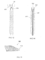
- Fig. 14 shows an inventive arrangement of two cells 310 between which a folded cooling plate 330 is arranged.
- the folded cooling plate 330 has two legs, which abut in each case on a main side of the cells 310. In one end section, the legs each follow a contour of an edge region of the cells 310, so that the legs each have a bend to the extensions 320 of the cells 310.
- a funnel-shaped recess 340 formed between the end portions of the legs of the folded cooling plate 330.
- Fig. 15 shows a perspective view of an embodiment of a for the arrangement Fig. 14 suitable cooling device 100. It can be seen that the cooling device 100 has parallel, wedge-shaped flat tubes 130.
- Fig. 16 shows a cross section of one of the flat tubes 130 from Fig. 15 , It can be seen that an outer contour of the flat tube 130 substantially corresponds to a shape of the in Fig. 14 shown funnel-shaped recess of the end portion of the cooling plate corresponds.
- Fig. 17 shows an illustration of a mounting of the flat tubes of a flat tube cooler 100 to cooling plates of a cell stack 300.
- An arrow 1710 indicates the direction in which the cooler 100, for example by gluing, is connected to the cell stack 300.
- Fig. 18 shows a sectional view of an assembly of flat tubes 130 and cooling plates 330, as a result of in connection with Fig. 17 . Illustrated assembly may be present.
- the wedge-shaped flat tubes 130 abut with their outer surfaces on the inner surfaces of the funnel-shaped recesses formed by the folded cooling plates 330.
- An adhesive 1810 provides bonding of the cooling plates 330 to the flat tubes 130.
- Fig. 19 shows a representation of an energy storage device according to an alternative embodiment of the invention. Shown are pairs of cells 310, between each of which a folded cooling plate 330 is arranged. No cooling plate may be disposed between adjacent pairs of cells 310.
- the folded cooling plates can be determined by means of Fig. 14 described, be formed.
- the cooling channels 130 may be connected to a plate 1910.
- the cooling plate 1910 may be an extrusion with cooling projections comprising the tubes or cooling channels 130.
- the channels 130 are disposed in the extensions of the cooling plate 1910.
- the cooling plate 1910 is disposed on the cooling plates.
- the channels 130 may also be disposed directly in the cooling plate 1910, adjacent to the extensions, as shown below.
- Fig. 20 shows a detailed view of a folded portion of the folded cooling plate 330 between two cells 310. Between the legs, an opening 2010 is formed for receiving, for example, pins for holding the energy storage device.
- one or more cells 310 may be connected to a double cooling plate 330, for example by gluing.
- the double, symmetrical cooling plate 330 consists of a centrally folded sheet metal, the open ends of a V-resp. Form wedge opening 340. This form facilitates the assembly of the flat tube cooler 100, for example by gluing with or without thermally conductive adhesive.
- the use of wedge-shaped flat tubes 130 additionally improves the assembly and allows a good bonding between flat tube 130 and V-shaped or wedge-shaped cooling plates 330.
- the tubes 130 can be configured as an extrusion profile for this purpose.
- the wedge-shaped connection increases the contact area compared to a parallel connection.
- the flat tubes 130 can also be designed as a single extrusion part and, for example, in the form of a plate 1910 with attached tubes 130 can also be mounted on the opposite side of the arresters. This allows cooling to take on structural tasks at the same time.
- the flow channels may be either in the tubes 130 or in the plate 1910. Several Cells with cooling plates can be combined to form a module with an extrusion part.
- the cooling plates 330 may be formed in the Abkant Scheme round. When folded heatsink 330, this area is thus tubular and can as a recording 2010 for pens or similar. serve. These inserted pins may e.g. be snapped into a receptacle of the housing or other structural part. This allows easy installation of the module in a total structure.
Applications Claiming Priority (2)
| Application Number | Priority Date | Filing Date | Title |
|---|---|---|---|
| DE102009052254A DE102009052254A1 (de) | 2009-11-06 | 2009-11-06 | Energiespeichervorrichtung |
| PCT/EP2010/066990 WO2011054952A1 (de) | 2009-11-06 | 2010-11-08 | Energiespeichervorrichtung |
Publications (2)
| Publication Number | Publication Date |
|---|---|
| EP2497145A1 EP2497145A1 (de) | 2012-09-12 |
| EP2497145B1 true EP2497145B1 (de) | 2014-04-02 |
Family
ID=43385149
Family Applications (1)
| Application Number | Title | Priority Date | Filing Date |
|---|---|---|---|
| EP20100779298 Not-in-force EP2497145B1 (de) | 2009-11-06 | 2010-11-08 | Energiespeichervorrichtung |
Country Status (7)
| Country | Link |
|---|---|
| US (1) | US20120301771A1 (ko) |
| EP (1) | EP2497145B1 (ko) |
| JP (1) | JP5810422B2 (ko) |
| KR (1) | KR20120091326A (ko) |
| CN (1) | CN102771004B (ko) |
| DE (1) | DE102009052254A1 (ko) |
| WO (1) | WO2011054952A1 (ko) |
Families Citing this family (28)
| Publication number | Priority date | Publication date | Assignee | Title |
|---|---|---|---|---|
| KR101205180B1 (ko) * | 2010-05-18 | 2012-11-27 | 주식회사 엘지화학 | 콤팩트하고 안정성이 우수한 냉각부재와 이를 포함하는 전지모듈 |
| KR101205181B1 (ko) * | 2010-05-18 | 2012-11-27 | 주식회사 엘지화학 | 신규한 구조의 냉각부재와 이를 포함하는 전지모듈 |
| WO2012086951A1 (ko) * | 2010-12-20 | 2012-06-28 | 주식회사 엘지화학 | 리튬 이차전지의 냉각방법 및 냉각시스템 |
| AT511666B1 (de) * | 2011-06-30 | 2015-05-15 | Avl List Gmbh | Wiederaufladbare elektrische batterie |
| KR101288121B1 (ko) * | 2011-08-24 | 2013-07-19 | 삼성에스디아이 주식회사 | 이차전지 및 이차전지 모듈 |
| JP5966314B2 (ja) * | 2011-10-28 | 2016-08-10 | 三洋電機株式会社 | 電源装置 |
| US9437903B2 (en) | 2012-01-31 | 2016-09-06 | Johnson Controls Technology Company | Method for cooling a lithium-ion battery pack |
| DE102012108762A1 (de) | 2012-09-18 | 2014-03-20 | Dr. Ing. H.C. F. Porsche Aktiengesellschaft | Batterieeinrichtung |
| DE102012018580B4 (de) | 2012-09-20 | 2015-06-11 | Jenoptik Industrial Metrology Germany Gmbh | Messvorrichtung und Messverfahren zur Inprozess-Messung an Prüflingen während eines Bearbeitungsvorganges an einer Bearbeitungsmaschine, insbesondere einer Schleifmaschine |
| DE102012112294A1 (de) * | 2012-12-14 | 2014-06-18 | Dr. Ing. H.C. F. Porsche Aktiengesellschaft | Elektrischer Energiespeicher |
| CN105324624B (zh) | 2013-04-24 | 2018-06-12 | 达纳加拿大公司 | 用于增压空气冷却器的翅片支承结构 |
| CN103840234A (zh) * | 2014-03-14 | 2014-06-04 | 吉林大学 | 电池组液流叠层换热扁管束结构及方法 |
| CN105020939B (zh) * | 2014-04-22 | 2018-12-11 | 杭州三花研究院有限公司 | 换热器及其组件 |
| EP3300164A4 (en) | 2015-06-12 | 2019-04-10 | LG Chem, Ltd. | BATTERY MODULE |
| KR101990590B1 (ko) * | 2015-08-17 | 2019-06-18 | 주식회사 엘지화학 | 배터리 모듈, 배터리 모듈을 포함하는 배터리 팩 및 배터리 팩을 포함하는 자동차 |
| KR102051109B1 (ko) * | 2015-10-08 | 2019-12-02 | 주식회사 엘지화학 | 전지 모듈 |
| CN105651091B (zh) * | 2016-02-19 | 2017-08-15 | 上海交通大学 | 传热增强型化学蓄热装置及应用该蓄热装置的蓄热系统 |
| DE102016213142A1 (de) * | 2016-07-19 | 2018-01-25 | Robert Bosch Gmbh | Batteriezelle, Batteriemodul und Verfahren zur Herstellung |
| US10230140B2 (en) * | 2016-09-27 | 2019-03-12 | GM Global Technology Operations LLC | Vehicle battery cooling system |
| KR102130818B1 (ko) | 2016-09-28 | 2020-07-06 | 주식회사 엘지화학 | 냉각 유로를 구비한 배터리 모듈 및 그 조립방법과 프레임 어셈블리 |
| EP3309858B1 (en) * | 2016-10-13 | 2019-07-10 | Samsung SDI Co., Ltd. | Battery module carrier, battery system and use of a modified h-beam as battery module carrier |
| KR102086127B1 (ko) * | 2016-10-31 | 2020-03-06 | 주식회사 엘지화학 | 배터리의 엣지 면에 직접 냉각 방식이 적용된 배터리 팩 |
| DE102019104949A1 (de) | 2019-01-07 | 2020-07-09 | Jenoptik Industrial Metrology Germany Gmbh | Messkopf einer Messvorrichtung zur Formmessung an wellenartigen Werkstücken |
| KR102159677B1 (ko) * | 2019-02-25 | 2020-09-24 | 정태연 | 열전소자를 이용한 배터리의 온도 모니터링 및 제어 장치와 그 방법 |
| DE102019109812B3 (de) * | 2019-04-12 | 2020-06-10 | Airbus Defence and Space GmbH | Kühlelement, Vorrichtung und Verfahren zum Kühlen von Batteriezellen, insbesondere für Pouch-Zellen, sowie Batteriepack |
| DE102020105308A1 (de) * | 2019-05-02 | 2020-11-05 | CrossLink GmbH | Temperiersystem für Lithium-Ionen-Batteriezellen |
| KR20210037885A (ko) * | 2019-09-30 | 2021-04-07 | 에스케이이노베이션 주식회사 | 배터리 모듈 |
| EP4310993A1 (en) * | 2022-07-21 | 2024-01-24 | Newfrey LLC | Battery apparatus with a cell tab cooling system |
Family Cites Families (26)
| Publication number | Priority date | Publication date | Assignee | Title |
|---|---|---|---|---|
| DE3242901A1 (de) * | 1982-11-20 | 1984-05-24 | Brown, Boveri & Cie Ag, 6800 Mannheim | Hochtemperatur-speicherbatterie |
| DE9002249U1 (ko) * | 1990-02-26 | 1990-05-03 | Varta Batterie Ag, 3000 Hannover, De | |
| JP2758348B2 (ja) * | 1993-10-01 | 1998-05-28 | 内浜化成株式会社 | バッテリーキャリヤ・カバー構造 |
| DE10223782B4 (de) | 2002-05-29 | 2005-08-25 | Daimlerchrysler Ag | Batterie mit wenigstens einer elektrochemischen Speicherzelle und einer Kühleinrichtung und Verwendung einer Batterie |
| DE10238235A1 (de) * | 2002-08-21 | 2004-03-04 | Daimlerchrysler Ag | Elektrochemischer Energiespeicher mit Wärmeaustauscherstruktur und mehreren elektrochemischen Speicherzellen |
| JP4000961B2 (ja) * | 2002-09-04 | 2007-10-31 | 日産自動車株式会社 | 組電池 |
| DE102004005394A1 (de) * | 2004-02-04 | 2005-08-25 | Daimlerchrysler Ag | Elektrochemischer Energiespeicher |
| DE102004005393A1 (de) * | 2004-02-04 | 2005-08-25 | Daimlerchrysler Ag | Elektrochemischer Energiespeicher |
| JP5292663B2 (ja) * | 2004-03-17 | 2013-09-18 | 日産自動車株式会社 | 組電池及び該組電池を搭載した車輌 |
| WO2006009062A1 (ja) * | 2004-07-20 | 2006-01-26 | Nec Corporation | 収納部材、収納ケースおよび筐体 |
| US20060093901A1 (en) * | 2004-10-28 | 2006-05-04 | Gun-Goo Lee | Secondary battery module and cooling apparatus for secondary battery module |
| WO2006135008A1 (ja) * | 2005-06-17 | 2006-12-21 | Nec Lamilion Energy, Ltd. | 電気デバイス集合体およびフィルム外装電気デバイス構造体 |
| JP2007042453A (ja) * | 2005-08-03 | 2007-02-15 | Fuji Heavy Ind Ltd | 蓄電体セルの整列構造 |
| KR100709261B1 (ko) * | 2005-11-15 | 2007-04-19 | 삼성에스디아이 주식회사 | 이차 전지 모듈 |
| WO2007063877A1 (ja) * | 2005-12-01 | 2007-06-07 | Nec Corporation | 電気デバイス集合体の製造方法 |
| JP4963902B2 (ja) * | 2006-08-31 | 2012-06-27 | 三洋電機株式会社 | 電源装置 |
| US7531270B2 (en) | 2006-10-13 | 2009-05-12 | Enerdel, Inc. | Battery pack with integral cooling and bussing devices |
| JP5142605B2 (ja) * | 2007-06-28 | 2013-02-13 | 三洋電機株式会社 | 車両用の電源装置 |
| DE102007063190B4 (de) * | 2007-08-06 | 2013-08-29 | Daimler Ag | Batterie, bestehend aus mehreren Einzelzellen, insbesondere für einen Hybridantrieb |
| KR100998845B1 (ko) * | 2007-11-09 | 2010-12-08 | 주식회사 엘지화학 | 방열특성의 전지모듈, 열교환 부재 및 이를 이용하는 중대형 전지팩 |
| KR101001320B1 (ko) * | 2007-11-09 | 2010-12-14 | 주식회사 엘지화학 | 향상된 열 안정성의 전지셀 및 이를 포함하는 중대형전지모듈 |
| JP2009176917A (ja) * | 2008-01-24 | 2009-08-06 | Fdk Corp | 非水電解質蓄電デバイス |
| US8465863B2 (en) * | 2008-04-09 | 2013-06-18 | GM Global Technology Operations LLC | Batteries and components thereof and methods of making and assembling the same |
| US8845762B2 (en) * | 2008-04-09 | 2014-09-30 | GM Global Technology Operations LLC | Batteries and components thereof and methods of making and assembling the same |
| EP2200109B1 (de) * | 2008-12-12 | 2015-01-07 | Behr GmbH & Co. KG | Halte- und Kühlungsvorrichtung für eine galvanische Zelle |
| US8383260B2 (en) * | 2010-02-26 | 2013-02-26 | GM Global Technology Operations LLC | U-formed cooling plate with solid fins for lithium pouch cells |
-
2009
- 2009-11-06 DE DE102009052254A patent/DE102009052254A1/de not_active Withdrawn
-
2010
- 2010-11-08 EP EP20100779298 patent/EP2497145B1/de not_active Not-in-force
- 2010-11-08 JP JP2012535883A patent/JP5810422B2/ja not_active Expired - Fee Related
- 2010-11-08 KR KR20127014744A patent/KR20120091326A/ko not_active Application Discontinuation
- 2010-11-08 WO PCT/EP2010/066990 patent/WO2011054952A1/de active Application Filing
- 2010-11-08 CN CN201080050323.1A patent/CN102771004B/zh not_active Expired - Fee Related
- 2010-11-08 US US13/505,920 patent/US20120301771A1/en not_active Abandoned
Also Published As
| Publication number | Publication date |
|---|---|
| WO2011054952A1 (de) | 2011-05-12 |
| CN102771004A (zh) | 2012-11-07 |
| US20120301771A1 (en) | 2012-11-29 |
| DE102009052254A1 (de) | 2011-05-12 |
| JP2013510385A (ja) | 2013-03-21 |
| JP5810422B2 (ja) | 2015-11-11 |
| KR20120091326A (ko) | 2012-08-17 |
| CN102771004B (zh) | 2015-04-01 |
| EP2497145A1 (de) | 2012-09-12 |
Similar Documents
| Publication | Publication Date | Title |
|---|---|---|
| EP2497145B1 (de) | Energiespeichervorrichtung | |
| EP2601705B1 (de) | Batteriezellen-kühlmodul und verfahren zum herstellen eines batteriezellen-kühlmoduls | |
| EP2153487B1 (de) | Elektrochemische energiespeichereinheit mit kühlvorrichtung | |
| DE112018002536T5 (de) | Gegenstrom-wärmetauscher mit seitlichen einlassarmaturen | |
| DE102009015351B4 (de) | Kühlanordnung für eine Speicherzellenanordnung für ein Fahrzeug | |
| DE102006059989A1 (de) | Anordnung zur Kühlung einer aus mehreren Einzelzellen bestehenden Batterie sowie Verfahren zur Herstellung der Anordnung | |
| DE102011109934B4 (de) | Batterie für ein Fahrzeug und Verfahren zum Fertigen einer solchen Batterie | |
| EP1835251A1 (de) | Vorrichtung zur Kühlung elektrischer Elemente | |
| WO2011057815A1 (de) | Batteriegehäuse zur aufnahme von elektrochemischen energiespeichereinrichtungen | |
| DE102018133006A1 (de) | Elektrospeicher und fahrzeug mit einem elektrospeicher | |
| DE102008034873A1 (de) | Batterie, insbesondere Fahrzeugbatterie | |
| WO2018188995A1 (de) | Batterie für ein kraftfahrzeug und kraftfahrzeug | |
| WO2013000882A1 (de) | Elektrische batterie | |
| DE102012217870A1 (de) | Wärmeübertrager | |
| WO2010115490A1 (de) | Elektroenergie-speichervorrichtung mit flachzellen und kühlkörpern | |
| DE102020121498A1 (de) | Energiespeichervorrichtung mit einem Batterie-Zellenmodul und einer Kühlvorrichtung, vorzugsweise für ein zumindest teilweise elektrisch angetriebenes Fahrzeug, und Verfahren zur Herstellung der Energiespeichervorrichtung | |
| WO2011120632A1 (de) | Batteriegehäuse zur aufnahme von elektrochemischen energiespeicherzellen | |
| DE102012218724A1 (de) | Anordnung und System zum Temperieren eines Energiespeichers, Batteriemodul mit einem solchen System und Verfahren zum Herstellen einer solchen Anordnung und eines solchen Systems | |
| DE102012218082A1 (de) | Trägerelement für eine elektrische Energiespeicherzelle mit Kühlkanälen mit einem nicht kreisförmigen Querschnitt, elektrischer Energiespeicher und Herstellverfahren für ein Trägerelement | |
| DE102017005315A1 (de) | Batteriekasten | |
| EP3753064B1 (de) | Batterie für ein kraftfahrzeug | |
| DE102011103965A1 (de) | Elektrochemische Batterie | |
| DE102012207995B4 (de) | Kühleinrichtung sowie Energiespeicher mit einer Kühleinrichtung | |
| EP2398109A1 (de) | Wärmetauscher und Verfahren zum Herstellen eines Wärmetauschers | |
| EP4070407B1 (de) | Modulschicht und daraus aufgebautes batteriesystem |
Legal Events
| Date | Code | Title | Description |
|---|---|---|---|
| PUAI | Public reference made under article 153(3) epc to a published international application that has entered the european phase |
Free format text: ORIGINAL CODE: 0009012 |
|
| 17P | Request for examination filed |
Effective date: 20120606 |
|
| AK | Designated contracting states |
Kind code of ref document: A1 Designated state(s): AL AT BE BG CH CY CZ DE DK EE ES FI FR GB GR HR HU IE IS IT LI LT LU LV MC MK MT NL NO PL PT RO RS SE SI SK SM TR |
|
| DAX | Request for extension of the european patent (deleted) | ||
| 17Q | First examination report despatched |
Effective date: 20130326 |
|
| RIC1 | Information provided on ipc code assigned before grant |
Ipc: H01M 10/50 20060101AFI20130807BHEP Ipc: H01M 2/02 20060101ALN20130807BHEP Ipc: H01M 10/04 20060101ALN20130807BHEP |
|
| GRAP | Despatch of communication of intention to grant a patent |
Free format text: ORIGINAL CODE: EPIDOSNIGR1 |
|
| INTG | Intention to grant announced |
Effective date: 20131016 |
|
| GRAS | Grant fee paid |
Free format text: ORIGINAL CODE: EPIDOSNIGR3 |
|
| REG | Reference to a national code |
Ref country code: DE Ref legal event code: R079 Ref document number: 502010006566 Country of ref document: DE Free format text: PREVIOUS MAIN CLASS: H01M0010500000 Ipc: H01M0002020000 |
|
| GRAA | (expected) grant |
Free format text: ORIGINAL CODE: 0009210 |
|
| AK | Designated contracting states |
Kind code of ref document: B1 Designated state(s): AL AT BE BG CH CY CZ DE DK EE ES FI FR GB GR HR HU IE IS IT LI LT LU LV MC MK MT NL NO PL PT RO RS SE SI SK SM TR |
|
| REG | Reference to a national code |
Ref country code: GB Ref legal event code: FG4D Free format text: NOT ENGLISH |
|
| RIC1 | Information provided on ipc code assigned before grant |
Ipc: H01M 2/02 20060101AFI20140224BHEP Ipc: H01M 10/6557 20140101ALI20140224BHEP Ipc: H01M 10/625 20140101ALI20140224BHEP Ipc: H01M 10/04 20060101ALI20140224BHEP Ipc: H01M 10/647 20140101ALI20140224BHEP Ipc: H01M 10/6567 20140101ALI20140224BHEP |
|
| REG | Reference to a national code |
Ref country code: AT Ref legal event code: REF Ref document number: 660606 Country of ref document: AT Kind code of ref document: T Effective date: 20140415 Ref country code: CH Ref legal event code: EP |
|
| REG | Reference to a national code |
Ref country code: IE Ref legal event code: FG4D Free format text: LANGUAGE OF EP DOCUMENT: GERMAN |
|
| REG | Reference to a national code |
Ref country code: DE Ref legal event code: R096 Ref document number: 502010006566 Country of ref document: DE Effective date: 20140515 |
|
| REG | Reference to a national code |
Ref country code: NL Ref legal event code: VDEP Effective date: 20140402 |
|
| REG | Reference to a national code |
Ref country code: LT Ref legal event code: MG4D |
|
| PG25 | Lapsed in a contracting state [announced via postgrant information from national office to epo] |
Ref country code: FI Free format text: LAPSE BECAUSE OF FAILURE TO SUBMIT A TRANSLATION OF THE DESCRIPTION OR TO PAY THE FEE WITHIN THE PRESCRIBED TIME-LIMIT Effective date: 20140402 Ref country code: CY Free format text: LAPSE BECAUSE OF FAILURE TO SUBMIT A TRANSLATION OF THE DESCRIPTION OR TO PAY THE FEE WITHIN THE PRESCRIBED TIME-LIMIT Effective date: 20140402 Ref country code: GR Free format text: LAPSE BECAUSE OF FAILURE TO SUBMIT A TRANSLATION OF THE DESCRIPTION OR TO PAY THE FEE WITHIN THE PRESCRIBED TIME-LIMIT Effective date: 20140703 Ref country code: BG Free format text: LAPSE BECAUSE OF FAILURE TO SUBMIT A TRANSLATION OF THE DESCRIPTION OR TO PAY THE FEE WITHIN THE PRESCRIBED TIME-LIMIT Effective date: 20140702 Ref country code: NL Free format text: LAPSE BECAUSE OF FAILURE TO SUBMIT A TRANSLATION OF THE DESCRIPTION OR TO PAY THE FEE WITHIN THE PRESCRIBED TIME-LIMIT Effective date: 20140402 Ref country code: CZ Free format text: LAPSE BECAUSE OF FAILURE TO SUBMIT A TRANSLATION OF THE DESCRIPTION OR TO PAY THE FEE WITHIN THE PRESCRIBED TIME-LIMIT Effective date: 20140402 Ref country code: NO Free format text: LAPSE BECAUSE OF FAILURE TO SUBMIT A TRANSLATION OF THE DESCRIPTION OR TO PAY THE FEE WITHIN THE PRESCRIBED TIME-LIMIT Effective date: 20140702 Ref country code: IS Free format text: LAPSE BECAUSE OF FAILURE TO SUBMIT A TRANSLATION OF THE DESCRIPTION OR TO PAY THE FEE WITHIN THE PRESCRIBED TIME-LIMIT Effective date: 20140802 Ref country code: LT Free format text: LAPSE BECAUSE OF FAILURE TO SUBMIT A TRANSLATION OF THE DESCRIPTION OR TO PAY THE FEE WITHIN THE PRESCRIBED TIME-LIMIT Effective date: 20140402 |
|
| PG25 | Lapsed in a contracting state [announced via postgrant information from national office to epo] |
Ref country code: LV Free format text: LAPSE BECAUSE OF FAILURE TO SUBMIT A TRANSLATION OF THE DESCRIPTION OR TO PAY THE FEE WITHIN THE PRESCRIBED TIME-LIMIT Effective date: 20140402 Ref country code: ES Free format text: LAPSE BECAUSE OF FAILURE TO SUBMIT A TRANSLATION OF THE DESCRIPTION OR TO PAY THE FEE WITHIN THE PRESCRIBED TIME-LIMIT Effective date: 20140402 Ref country code: HR Free format text: LAPSE BECAUSE OF FAILURE TO SUBMIT A TRANSLATION OF THE DESCRIPTION OR TO PAY THE FEE WITHIN THE PRESCRIBED TIME-LIMIT Effective date: 20140402 Ref country code: RS Free format text: LAPSE BECAUSE OF FAILURE TO SUBMIT A TRANSLATION OF THE DESCRIPTION OR TO PAY THE FEE WITHIN THE PRESCRIBED TIME-LIMIT Effective date: 20140402 Ref country code: SE Free format text: LAPSE BECAUSE OF FAILURE TO SUBMIT A TRANSLATION OF THE DESCRIPTION OR TO PAY THE FEE WITHIN THE PRESCRIBED TIME-LIMIT Effective date: 20140402 Ref country code: PL Free format text: LAPSE BECAUSE OF FAILURE TO SUBMIT A TRANSLATION OF THE DESCRIPTION OR TO PAY THE FEE WITHIN THE PRESCRIBED TIME-LIMIT Effective date: 20140402 |
|
| PG25 | Lapsed in a contracting state [announced via postgrant information from national office to epo] |
Ref country code: PT Free format text: LAPSE BECAUSE OF FAILURE TO SUBMIT A TRANSLATION OF THE DESCRIPTION OR TO PAY THE FEE WITHIN THE PRESCRIBED TIME-LIMIT Effective date: 20140804 |
|
| REG | Reference to a national code |
Ref country code: DE Ref legal event code: R097 Ref document number: 502010006566 Country of ref document: DE |
|
| PG25 | Lapsed in a contracting state [announced via postgrant information from national office to epo] |
Ref country code: SK Free format text: LAPSE BECAUSE OF FAILURE TO SUBMIT A TRANSLATION OF THE DESCRIPTION OR TO PAY THE FEE WITHIN THE PRESCRIBED TIME-LIMIT Effective date: 20140402 Ref country code: EE Free format text: LAPSE BECAUSE OF FAILURE TO SUBMIT A TRANSLATION OF THE DESCRIPTION OR TO PAY THE FEE WITHIN THE PRESCRIBED TIME-LIMIT Effective date: 20140402 Ref country code: DK Free format text: LAPSE BECAUSE OF FAILURE TO SUBMIT A TRANSLATION OF THE DESCRIPTION OR TO PAY THE FEE WITHIN THE PRESCRIBED TIME-LIMIT Effective date: 20140402 Ref country code: RO Free format text: LAPSE BECAUSE OF FAILURE TO SUBMIT A TRANSLATION OF THE DESCRIPTION OR TO PAY THE FEE WITHIN THE PRESCRIBED TIME-LIMIT Effective date: 20140402 |
|
| PLBE | No opposition filed within time limit |
Free format text: ORIGINAL CODE: 0009261 |
|
| STAA | Information on the status of an ep patent application or granted ep patent |
Free format text: STATUS: NO OPPOSITION FILED WITHIN TIME LIMIT |
|
| 26N | No opposition filed |
Effective date: 20150106 |
|
| REG | Reference to a national code |
Ref country code: DE Ref legal event code: R082 Ref document number: 502010006566 Country of ref document: DE Representative=s name: GRAUEL, ANDREAS, DIPL.-PHYS. DR. RER. NAT., DE |
|
| PG25 | Lapsed in a contracting state [announced via postgrant information from national office to epo] |
Ref country code: IT Free format text: LAPSE BECAUSE OF FAILURE TO SUBMIT A TRANSLATION OF THE DESCRIPTION OR TO PAY THE FEE WITHIN THE PRESCRIBED TIME-LIMIT Effective date: 20140402 |
|
| REG | Reference to a national code |
Ref country code: DE Ref legal event code: R097 Ref document number: 502010006566 Country of ref document: DE Effective date: 20150106 |
|
| REG | Reference to a national code |
Ref country code: DE Ref legal event code: R082 Ref document number: 502010006566 Country of ref document: DE Representative=s name: GRAUEL, ANDREAS, DIPL.-PHYS. DR. RER. NAT., DE Effective date: 20150324 Ref country code: DE Ref legal event code: R081 Ref document number: 502010006566 Country of ref document: DE Owner name: MAHLE INTERNATIONAL GMBH, DE Free format text: FORMER OWNER: BEHR GMBH & CO. KG, 70469 STUTTGART, DE Effective date: 20150324 |
|
| PG25 | Lapsed in a contracting state [announced via postgrant information from national office to epo] |
Ref country code: RS Free format text: LAPSE BECAUSE OF FAILURE TO SUBMIT A TRANSLATION OF THE DESCRIPTION OR TO PAY THE FEE WITHIN THE PRESCRIBED TIME-LIMIT Effective date: 20141119 |
|
| PG25 | Lapsed in a contracting state [announced via postgrant information from national office to epo] |
Ref country code: BE Free format text: LAPSE BECAUSE OF NON-PAYMENT OF DUE FEES Effective date: 20141130 Ref country code: LU Free format text: LAPSE BECAUSE OF FAILURE TO SUBMIT A TRANSLATION OF THE DESCRIPTION OR TO PAY THE FEE WITHIN THE PRESCRIBED TIME-LIMIT Effective date: 20141108 Ref country code: MC Free format text: LAPSE BECAUSE OF FAILURE TO SUBMIT A TRANSLATION OF THE DESCRIPTION OR TO PAY THE FEE WITHIN THE PRESCRIBED TIME-LIMIT Effective date: 20140402 |
|
| REG | Reference to a national code |
Ref country code: CH Ref legal event code: PL |
|
| GBPC | Gb: european patent ceased through non-payment of renewal fee |
Effective date: 20141108 |
|
| PG25 | Lapsed in a contracting state [announced via postgrant information from national office to epo] |
Ref country code: SI Free format text: LAPSE BECAUSE OF FAILURE TO SUBMIT A TRANSLATION OF THE DESCRIPTION OR TO PAY THE FEE WITHIN THE PRESCRIBED TIME-LIMIT Effective date: 20140402 Ref country code: LI Free format text: LAPSE BECAUSE OF NON-PAYMENT OF DUE FEES Effective date: 20141130 Ref country code: CH Free format text: LAPSE BECAUSE OF NON-PAYMENT OF DUE FEES Effective date: 20141130 |
|
| REG | Reference to a national code |
Ref country code: IE Ref legal event code: MM4A |
|
| PG25 | Lapsed in a contracting state [announced via postgrant information from national office to epo] |
Ref country code: GB Free format text: LAPSE BECAUSE OF NON-PAYMENT OF DUE FEES Effective date: 20141108 Ref country code: IE Free format text: LAPSE BECAUSE OF NON-PAYMENT OF DUE FEES Effective date: 20141108 |
|
| REG | Reference to a national code |
Ref country code: FR Ref legal event code: PLFP Year of fee payment: 6 |
|
| PG25 | Lapsed in a contracting state [announced via postgrant information from national office to epo] |
Ref country code: SM Free format text: LAPSE BECAUSE OF FAILURE TO SUBMIT A TRANSLATION OF THE DESCRIPTION OR TO PAY THE FEE WITHIN THE PRESCRIBED TIME-LIMIT Effective date: 20140402 |
|
| PG25 | Lapsed in a contracting state [announced via postgrant information from national office to epo] |
Ref country code: TR Free format text: LAPSE BECAUSE OF FAILURE TO SUBMIT A TRANSLATION OF THE DESCRIPTION OR TO PAY THE FEE WITHIN THE PRESCRIBED TIME-LIMIT Effective date: 20140402 Ref country code: MT Free format text: LAPSE BECAUSE OF FAILURE TO SUBMIT A TRANSLATION OF THE DESCRIPTION OR TO PAY THE FEE WITHIN THE PRESCRIBED TIME-LIMIT Effective date: 20140402 Ref country code: HU Free format text: LAPSE BECAUSE OF FAILURE TO SUBMIT A TRANSLATION OF THE DESCRIPTION OR TO PAY THE FEE WITHIN THE PRESCRIBED TIME-LIMIT; INVALID AB INITIO Effective date: 20101108 |
|
| REG | Reference to a national code |
Ref country code: FR Ref legal event code: PLFP Year of fee payment: 7 |
|
| REG | Reference to a national code |
Ref country code: AT Ref legal event code: MM01 Ref document number: 660606 Country of ref document: AT Kind code of ref document: T Effective date: 20151108 |
|
| PG25 | Lapsed in a contracting state [announced via postgrant information from national office to epo] |
Ref country code: AT Free format text: LAPSE BECAUSE OF NON-PAYMENT OF DUE FEES Effective date: 20151108 |
|
| REG | Reference to a national code |
Ref country code: FR Ref legal event code: PLFP Year of fee payment: 8 |
|
| PG25 | Lapsed in a contracting state [announced via postgrant information from national office to epo] |
Ref country code: MK Free format text: LAPSE BECAUSE OF FAILURE TO SUBMIT A TRANSLATION OF THE DESCRIPTION OR TO PAY THE FEE WITHIN THE PRESCRIBED TIME-LIMIT Effective date: 20140402 |
|
| PG25 | Lapsed in a contracting state [announced via postgrant information from national office to epo] |
Ref country code: AL Free format text: LAPSE BECAUSE OF FAILURE TO SUBMIT A TRANSLATION OF THE DESCRIPTION OR TO PAY THE FEE WITHIN THE PRESCRIBED TIME-LIMIT Effective date: 20140402 |
|
| REG | Reference to a national code |
Ref country code: DE Ref legal event code: R082 Ref document number: 502010006566 Country of ref document: DE Representative=s name: DTS PATENT- UND RECHTSANWAELTE SCHNEKENBUEHL U, DE |
|
| REG | Reference to a national code |
Ref country code: DE Ref legal event code: R082 Ref document number: 502010006566 Country of ref document: DE Representative=s name: DTS PATENT- UND RECHTSANWAELTE SCHNEKENBUEHL U, DE Ref country code: DE Ref legal event code: R081 Ref document number: 502010006566 Country of ref document: DE Owner name: ARKISS IP UG (HAFTUNGSBESCHRAENKT), DE Free format text: FORMER OWNER: MAHLE INTERNATIONAL GMBH, 70376 STUTTGART, DE |
|
| REG | Reference to a national code |
Ref country code: DE Ref legal event code: R084 Ref document number: 502010006566 Country of ref document: DE |
|
| REG | Reference to a national code |
Ref country code: DE Ref legal event code: R079 Ref document number: 502010006566 Country of ref document: DE Free format text: PREVIOUS MAIN CLASS: H01M0002020000 Ipc: H01M0050100000 |
|
| PGFP | Annual fee paid to national office [announced via postgrant information from national office to epo] |
Ref country code: DE Payment date: 20211124 Year of fee payment: 12 Ref country code: FR Payment date: 20211119 Year of fee payment: 12 |
|
| REG | Reference to a national code |
Ref country code: DE Ref legal event code: R119 Ref document number: 502010006566 Country of ref document: DE |
|
| PG25 | Lapsed in a contracting state [announced via postgrant information from national office to epo] |
Ref country code: DE Free format text: LAPSE BECAUSE OF NON-PAYMENT OF DUE FEES Effective date: 20230601 |
|
| PG25 | Lapsed in a contracting state [announced via postgrant information from national office to epo] |
Ref country code: FR Free format text: LAPSE BECAUSE OF NON-PAYMENT OF DUE FEES Effective date: 20221130 |