EP2496898B1 - Kältegerät und eisbereiter dafür - Google Patents
Kältegerät und eisbereiter dafür Download PDFInfo
- Publication number
- EP2496898B1 EP2496898B1 EP10770796.0A EP10770796A EP2496898B1 EP 2496898 B1 EP2496898 B1 EP 2496898B1 EP 10770796 A EP10770796 A EP 10770796A EP 2496898 B1 EP2496898 B1 EP 2496898B1
- Authority
- EP
- European Patent Office
- Prior art keywords
- ice maker
- lever
- tray
- axis
- refrigeration device
- Prior art date
- Legal status (The legal status is an assumption and is not a legal conclusion. Google has not performed a legal analysis and makes no representation as to the accuracy of the status listed.)
- Active
Links
Images



Classifications
-
- F—MECHANICAL ENGINEERING; LIGHTING; HEATING; WEAPONS; BLASTING
- F25—REFRIGERATION OR COOLING; COMBINED HEATING AND REFRIGERATION SYSTEMS; HEAT PUMP SYSTEMS; MANUFACTURE OR STORAGE OF ICE; LIQUEFACTION SOLIDIFICATION OF GASES
- F25C—PRODUCING, WORKING OR HANDLING ICE
- F25C1/00—Producing ice
- F25C1/22—Construction of moulds; Filling devices for moulds
- F25C1/24—Construction of moulds; Filling devices for moulds for refrigerators, e.g. freezing trays
-
- F—MECHANICAL ENGINEERING; LIGHTING; HEATING; WEAPONS; BLASTING
- F25—REFRIGERATION OR COOLING; COMBINED HEATING AND REFRIGERATION SYSTEMS; HEAT PUMP SYSTEMS; MANUFACTURE OR STORAGE OF ICE; LIQUEFACTION SOLIDIFICATION OF GASES
- F25C—PRODUCING, WORKING OR HANDLING ICE
- F25C5/00—Working or handling ice
- F25C5/02—Apparatus for disintegrating, removing or harvesting ice
- F25C5/04—Apparatus for disintegrating, removing or harvesting ice without the use of saws
- F25C5/06—Apparatus for disintegrating, removing or harvesting ice without the use of saws by deforming bodies with which the ice is in contact, e.g. using inflatable members
-
- F—MECHANICAL ENGINEERING; LIGHTING; HEATING; WEAPONS; BLASTING
- F25—REFRIGERATION OR COOLING; COMBINED HEATING AND REFRIGERATION SYSTEMS; HEAT PUMP SYSTEMS; MANUFACTURE OR STORAGE OF ICE; LIQUEFACTION SOLIDIFICATION OF GASES
- F25C—PRODUCING, WORKING OR HANDLING ICE
- F25C2305/00—Special arrangements or features for working or handling ice
- F25C2305/022—Harvesting ice including rotating or tilting or pivoting of a mould or tray
- F25C2305/0221—Harvesting ice including rotating or tilting or pivoting of a mould or tray rotating ice mould
-
- F—MECHANICAL ENGINEERING; LIGHTING; HEATING; WEAPONS; BLASTING
- F25—REFRIGERATION OR COOLING; COMBINED HEATING AND REFRIGERATION SYSTEMS; HEAT PUMP SYSTEMS; MANUFACTURE OR STORAGE OF ICE; LIQUEFACTION SOLIDIFICATION OF GASES
- F25C—PRODUCING, WORKING OR HANDLING ICE
- F25C2400/00—Auxiliary features or devices for producing, working or handling ice
- F25C2400/06—Multiple ice moulds or trays therefor
-
- F—MECHANICAL ENGINEERING; LIGHTING; HEATING; WEAPONS; BLASTING
- F25—REFRIGERATION OR COOLING; COMBINED HEATING AND REFRIGERATION SYSTEMS; HEAT PUMP SYSTEMS; MANUFACTURE OR STORAGE OF ICE; LIQUEFACTION SOLIDIFICATION OF GASES
- F25C—PRODUCING, WORKING OR HANDLING ICE
- F25C2500/00—Problems to be solved
- F25C2500/06—Spillage or flooding of water
-
- F—MECHANICAL ENGINEERING; LIGHTING; HEATING; WEAPONS; BLASTING
- F25—REFRIGERATION OR COOLING; COMBINED HEATING AND REFRIGERATION SYSTEMS; HEAT PUMP SYSTEMS; MANUFACTURE OR STORAGE OF ICE; LIQUEFACTION SOLIDIFICATION OF GASES
- F25C—PRODUCING, WORKING OR HANDLING ICE
- F25C5/00—Working or handling ice
- F25C5/20—Distributing ice
- F25C5/22—Distributing ice particularly adapted for household refrigerators
Definitions
- the present invention relates to an ice maker for use in a refrigerator, in particular a household refrigerator. It further relates to a refrigeration device, in particular a household refrigerator, in which such an icemaker is used.
- a refrigerator with an icemaker in which a motor twists an elastic tray to demold pieces of ice formed in the tray is off DE 41 13 767 A1 known.
- the cost of such an ice maker can be significantly reduced if the engine is omitted and instead the ice maker tray is manually twisted, as in FIG DE 10 2006 017 804 A1 described.
- an ice maker is known, in which a tray is housed around a longitudinal axis rotatable and twistable in an assembled from two half-shells housing. At one end of the housing, at a boundary between the two half shells, a cylindrical knob is brought out of the housing which a user can grasp to turn and twist the tray.
- the torque required for reliable removal of all pieces of ice of the tray can be so great that it is difficult for a user to apply it.
- the documents JP 61 175872 U and JP 49 101343 U both disclose an ice maker with a tray twistable about an axis.
- the object of the invention is to provide an ice maker, in which the demolding of the finished pieces of ice is facilitated, and not unnecessarily space is claimed when not in use.
- the lever does not unnecessarily take up space when not in use, it is adjustable between a rest position and a projecting over the front side actuating position, wherein the distance of a handle portion of the lever from the axis in the operating position is greater than in the rest position.
- the lever In the rest position, the lever is preferably not over a longitudinal wall of the tray over.
- the adjustment movement may be a shift; Preferably, it is a pivoting movement.
- the lever When the tray is pivotally suspended in a frame about a first axis, in particular between a freezing position and a demolding position, the lever is preferably pivotable between the rest position and the actuating position about a second axis parallel to the first axis. This makes it possible to use the lever in a continuous movement both for pivoting the tray and for twisting.
- the lever and the pivoting freedom of the tablet limiting stop are suitably arranged on opposite end faces of the tray to twist this effectively.
- a second tray is further pivotable about the first axis, and the lever is disposed between the first and the second tray.
- the lever In the rest position, the lever can be supported on a shaft of the tray and thereby held so that it can be gripped by a user quickly and safely.
- the first pivot axis is aligned in the width direction of a housing of the refrigerator.
- the tray is preferably divided in a conventional manner by partitions into several compartments.
- Outer walls of the tray which are 15% to 70%, preferably 30% to 40% higher than the intermediate walls, so projecting over the upper edges of the intermediate walls, can prevent spilling over when the tray is moved, while its subjects contain liquid water ,
- a portion of at least one of the outer walls projecting above the intermediate walls is preferably concavely curved on its inner side in order to deflect water which floats against the outer wall due to an acceleration acting on the tray, in a continuous, substantially laminar movement and to avoid splashing.
- such an icemaker is mounted on a door of the refrigerator and movable with the door.
- This icemaker is easily accessible for filling and emptying, and with the door open, neither the icemaker obstructs access to the interior of the refrigerator, nor does a ceiling of the interior obstruct the filling of water into the tray.
- the icemaker can be removably mounted in a body of the refrigeration device to allow access to parts of the interior located behind the icemaker or to be easily accessible for filling or for the removal of ice.
- such a retractable ice maker can be integrated into a drawer of the refrigerator.
- a container for ice pieces may be provided, which in turn is pulled out of the drawer.
- Fig. 1 is an interior view of a refrigerator door 14.
- the door 14 has a known construction with a molded sheet metal outer skin 15, a plastic deep-drawn inner wall 16 and enclosed by outer skin 15 and inner wall 16, filled with heat-insulating synthetic resin foam gap.
- On the inner wall 16 a large flat projection 17 is tightened, which engages in the closed position of the door 14 in an interior of a refrigeration appliance body.
- arms 18 are formed during deep drawing of the inner wall, in each case in pairs with respect to Fig. 3 more precisely described ice maker Tray 1 hold.
- a pin 22 is formed in each case abuts from below against the respective adjacent arm 18 when a user grasps the lever 20 and moves away from the door 14 to the trays 1 to a parallel to the door 14 through the arms 18 extending axis 23 in the in Fig. 2 to swing shown Entformungswolf.
- a container 24 is expediently mounted on the door 14 under the trays 1.
- the container 24 may in particular be of identical construction with door cabinets, not shown in the figures, mounted elsewhere on the inside of the door.
- the attachment of the icemaker trays 1 to the door 14 entails that they are exposed to accelerations and delays that can move liquid water in the compartments 2 in motion and can bring under adverse circumstances to spill over. In particular, if after filling the trays 1 with water, the door 14 is closed, an abrupt delay is hardly avoidable when the door 14 strikes against the body.
- Fig. 3 shows a cross section of a tray 1.
- the sectional plane extends through two longitudinal walls 6 and two compartments 2 of the tray 1; further compartments 2 adjoin the cutting plane transversely.
- the compartments 2 are separated from each other by intermediate walls 3, which are provided at their upper edges with notches 4 through which water can flow from a full compartment 2 into an adjacent one.
- the water level 13 of the resting tablet is therefore in operation usually just above the lower edge of the notches 4th
- the compartments 2 inside are free of sharp edges and have a downwardly continuously decreasing cross-section.
- the partition walls 3 and longitudinal or end walls 5, 6 pass over continuously curved sections 7 in bottom surfaces 8 of the compartments.
- the slope of the end walls 5 increases continuously from top to bottom, and at least above the intermediate walls 3, the end walls 5 extend vertically.
- the longitudinal walls 6, however, are divided behind the vertical into three successive sections.
- a lower portion 9 increases as in the end walls 5, the wall slope from bottom to top continuously. It reaches its highest value at a height of the notches 4 extending horizontal edge 10. Above this edge 10 is followed by a middle portion 11, which is less steep than the adjacent lower portion 9.
- the middle portion 11 and an upper portion 12th go over a continuous curvature into each other.
- the side wall is similarly steep as in the lower portion 9; she can even like in Fig. 3 shown, overhang inside.
- FIG. 3 A course of the water level, which results when the random door 14 abruptly comes to a standstill on the carcass, is in Fig. 3 denoted by 13 '.
- the water does not follow the delay of the door immediately, so that on the left edges of the compartments 2 the water level rises.
- the water of the right compartment 2 can rise above the intermediate wall 3 and part of the water spills over into the left compartment 2.
- the sloshing against the left longitudinal wall 6 water meets there first on the relatively weak rising middle section 11. It is therefore not like the door 14 abruptly delayed, but continuously deflected upward. This reduces the risk of splashing. If the delay of the tray 1 is so strong that the water rising on the left longitudinal wall 6 exceeds its upper edge, it will receive a rightward impulse by the overhang of the upper portion 12, so that it will fall back into the compartment 2 instead of the side wall 6 to overcome.
- middle and top sections 11 and 12 which provides effective protection against spills, depends on the accelerations that occur and the duration of their impact; in practice it is between one and two thirds of the height of the lower section 9.
- the trays 1 must maintain a non-negligible distance from the projection 17 to the in the rest position of Fig. 1 To make room for over the door 14 facing the longitudinal walls 6 facing the trays 1 protruding free end of the lever 20. The larger this distance, the longer the lever 20 may be, and the lower is the force that the user on the lever 20 has to exercise for releasing the pieces of ice from the trays 1.
- the gap between the door 14 and the trays 1 leads to a poor space utilization.
- a lever 20 is pivotally mounted about an axis 25 which is parallel to the axis 23 and spaced therefrom. In a rest position, the lever 20 rests on a shaft 26 extending along the axis 23 and connecting the trays 1.
- a grip portion 27 at the free end of the lever 20 is the (in Fig. 4 not shown) door 14 facing, but without over the longitudinal walls 6 to the door out. The handle portion 27 is in the rest position slightly above the trays 1 so that it is comfortable to grip by a user.
- Fig. 5 shows a schematic section through the arrangement of Fig. 4 along a plane extending between the trays 1 level. As can be seen here, abuts in a relation to the rest position by slightly more than 90 ° tilted stop position, a projection 28 of the lever 20 against an extending between the end walls 5 of the trays facing web 29, so that the lever 20 when he over the Stop position is pivoted out, the trays 1 entrains and the axis 23 to the common pivot axis of the lever 20 and the trays 1 is.
- Fig. 6 shows the arrangement of Fig. 4 in this twisted state.
- the open sides of the compartments 2 are directed downwards, so that by deformation of the compartments 2 loose pieces of ice fall out of the compartments free.
- Fig. 7 shows you one Fig. 5 analog section according to a second embodiment of the invention.
- the mutually facing end faces 5 of the two trays 1 facing each other arcuate grooves 32, and mounted between the trays 1, here also arcuately curved lever 20 has in the grooves 32 engaging ribs 33.
- the lever 20 is displaceable along the grooves 32 between a rest position shown in dashed lines and an actuating position in which a detent 34 of each rib 33 is engaged in a recess 35 at one end of the grooves 32.
- the detents 34 are pressed into the recess 35, so that the trays 1 can be pivoted and finally twisted, as in FIG Fig. 6 shown.
- the trays of the first and second embodiment may differ from the illustration in Fig. 4 to 7 as overspray you spray protection as with respect to Fig. 3 described articulated side walls 5, 6 have.
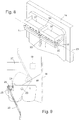
- Fig. 8 shows in one too Fig. 1 analog view of an embodiment of an icemaker, in which this problem is resolved. Again, between two trays 1, a lever 20 about an axis parallel to the pivot axis 23 of the trays 1 axis 25 (FIGS. Fig. 9 ) hinged. The lever 20 is suspended in the rest position of Fig. 8 free down.
- Fig. 9 shows a section through the ice maker of Fig. 8 , again along a plane extending between the trays 1.
- the pivoting freedom of the handle 20 is limited in relation to the trays 1 by a projection 28 of the lever 20, which abuts a web connecting the trays 1 29.
- the direction of rotation of the pivoting movement is opposite to that of the previous embodiments; the top of the trays 1 is pivoted towards the door 14 until the pins 22 hit the tops of the arms 18.
- the lever 20 is in a gap 36 between two arranged on the trays 1 containers 37.
- Fig. 10 shows a perspective view of an ice maker according to a fifth embodiment.
- This icemaker is very similar to that of the Fig. 8
- the trays 1 are not held on protruding from a door arms, but in a surrounding them on four sides, top and bottom open frame 39th
- Der Eisker der Fig. 10 is intended to be mounted in a drawer 40 of a refrigerator body 41, as in Fig. 11 shown.
- a compartment 42 is divided into which the ice maker of can be used positively above.
- Narrow webs 43 surround a large-area opening 44 at the bottom of the compartment 42.
- the webs 43 serve to support the frame 39.
- the opening 44 opens into a drawer 45 which can be pulled out at the front of the pull-out box 40.
- the lever 20 hangs in its rest position over a rear wall 46 of the compartment 42 away in a lying behind main compartment 47 of the pull-out box 40th
- a user can pull out the pull-out box 40 from the body 41 and pivot the free end of the lever 20 facing away from it and pull it towards itself until the projections 22 of the trays against inclined surfaces 48 (FIGS. Fig. 10 ) of the frame 39 and the distortion of the trays 1 begins. Pieces of ice ejected by the twist fall through the opening 44 into the drawer 45 and can be removed therefrom.
Landscapes
- Engineering & Computer Science (AREA)
- Physics & Mathematics (AREA)
- Mechanical Engineering (AREA)
- Thermal Sciences (AREA)
- General Engineering & Computer Science (AREA)
- Production, Working, Storing, Or Distribution Of Ice (AREA)
Applications Claiming Priority (2)
| Application Number | Priority Date | Filing Date | Title |
|---|---|---|---|
| DE102009046026A DE102009046026A1 (de) | 2009-10-27 | 2009-10-27 | Kältegerät und Eisbereiter dafür |
| PCT/EP2010/065650 WO2011051131A2 (de) | 2009-10-27 | 2010-10-18 | Kältegerät und eisbereiter dafür |
Publications (2)
| Publication Number | Publication Date |
|---|---|
| EP2496898A2 EP2496898A2 (de) | 2012-09-12 |
| EP2496898B1 true EP2496898B1 (de) | 2016-12-14 |
Family
ID=43828528
Family Applications (1)
| Application Number | Title | Priority Date | Filing Date |
|---|---|---|---|
| EP10770796.0A Active EP2496898B1 (de) | 2009-10-27 | 2010-10-18 | Kältegerät und eisbereiter dafür |
Country Status (5)
| Country | Link |
|---|---|
| EP (1) | EP2496898B1 (pl) |
| CN (1) | CN102803872B (pl) |
| DE (1) | DE102009046026A1 (pl) |
| PL (1) | PL2496898T3 (pl) |
| WO (1) | WO2011051131A2 (pl) |
Cited By (2)
| Publication number | Priority date | Publication date | Assignee | Title |
|---|---|---|---|---|
| CN109813021A (zh) * | 2017-11-22 | 2019-05-28 | 合肥华凌股份有限公司 | 制冰盒以及冷藏设备 |
| US11674730B2 (en) * | 2018-10-02 | 2023-06-13 | Lg Electronics Inc. | Ice maker and refrigerator including same |
Families Citing this family (5)
| Publication number | Priority date | Publication date | Assignee | Title |
|---|---|---|---|---|
| DE102012213979A1 (de) | 2012-08-07 | 2014-02-13 | BSH Bosch und Siemens Hausgeräte GmbH | Kältegerät mit Eisbereiter |
| DE102012223631A1 (de) * | 2012-12-18 | 2014-06-18 | BSH Bosch und Siemens Hausgeräte GmbH | Kältegerät mit einem Eisbereiter mit Doppel-Anschlägen |
| CN104215025B (zh) * | 2013-06-04 | 2016-12-28 | 苏州三星电子有限公司 | 一种冰箱门体用活动储物盒 |
| CN104180574B (zh) * | 2014-07-21 | 2016-04-27 | 海信容声(广东)冰箱有限公司 | 一种冰箱制冰装置 |
| DE102015002424B4 (de) * | 2015-02-26 | 2022-02-24 | Emz-Hanauer Gmbh & Co. Kgaa | Kühl- oder/und Gefriergerät mit einem Eisbereitungsmodul |
Family Cites Families (12)
| Publication number | Priority date | Publication date | Assignee | Title |
|---|---|---|---|---|
| US1740919A (en) * | 1928-10-05 | 1929-12-24 | Copeman Lab Co | Flexible sharp-freezing container |
| US2381068A (en) * | 1942-03-16 | 1945-08-07 | Lutes Herschel | Refrigerating apparatus |
| US3394558A (en) * | 1966-09-21 | 1968-07-30 | Westinghouse Electric Corp | Automatic fill arrangement for ice trays |
| JPS49101343U (pl) * | 1972-12-20 | 1974-08-31 | ||
| JPS5647490Y2 (pl) * | 1976-05-28 | 1981-11-06 | ||
| JPS61175872U (pl) * | 1985-04-19 | 1986-11-01 | ||
| JP2609741B2 (ja) | 1990-04-26 | 1997-05-14 | 株式会社東芝 | 自動製氷装置付冷蔵庫 |
| JPH09101343A (ja) * | 1995-10-06 | 1997-04-15 | Sony Corp | 電子部品計測装置の接触装置 |
| US7610772B2 (en) * | 2006-03-06 | 2009-11-03 | Whirlpool Corporation | Ice level sensing system for a bottom freezer refrigerator |
| DE102006017804A1 (de) | 2006-04-18 | 2007-10-25 | BSH Bosch und Siemens Hausgeräte GmbH | Haushaltsgerät |
| AU2007285171B2 (en) * | 2006-08-15 | 2010-05-27 | Lg Electronics Inc. | Ice tray assembly and refrigerator having same |
| US8272232B2 (en) * | 2006-09-06 | 2012-09-25 | Lg Electronics Inc. | Refrigerator |
-
2009
- 2009-10-27 DE DE102009046026A patent/DE102009046026A1/de not_active Withdrawn
-
2010
- 2010-10-18 EP EP10770796.0A patent/EP2496898B1/de active Active
- 2010-10-18 PL PL10770796T patent/PL2496898T3/pl unknown
- 2010-10-18 WO PCT/EP2010/065650 patent/WO2011051131A2/de not_active Ceased
- 2010-10-18 CN CN201080048657.5A patent/CN102803872B/zh active Active
Cited By (2)
| Publication number | Priority date | Publication date | Assignee | Title |
|---|---|---|---|---|
| CN109813021A (zh) * | 2017-11-22 | 2019-05-28 | 合肥华凌股份有限公司 | 制冰盒以及冷藏设备 |
| US11674730B2 (en) * | 2018-10-02 | 2023-06-13 | Lg Electronics Inc. | Ice maker and refrigerator including same |
Also Published As
| Publication number | Publication date |
|---|---|
| DE102009046026A1 (de) | 2011-05-05 |
| WO2011051131A3 (de) | 2012-02-02 |
| CN102803872A (zh) | 2012-11-28 |
| CN102803872B (zh) | 2015-04-29 |
| WO2011051131A2 (de) | 2011-05-05 |
| PL2496898T3 (pl) | 2017-03-31 |
| EP2496898A2 (de) | 2012-09-12 |
Similar Documents
| Publication | Publication Date | Title |
|---|---|---|
| EP2496898B1 (de) | Kältegerät und eisbereiter dafür | |
| WO2008077742A2 (de) | Kältegerät | |
| DE10107646A1 (de) | Auszugskasten für ein Kältegerät | |
| EP2494286B1 (de) | Kältegerät mit eisbereiter | |
| EP2494284B1 (de) | Kältegerät mit eisbereiter | |
| EP2131125B1 (de) | Türablagefach für ein Kältegerät | |
| WO2012136563A2 (de) | Eisstückbereitersystem und kältegerät mit einem solchen eisstückbereitersystem | |
| EP2218992A2 (de) | Kältegerät | |
| EP2494282A2 (de) | Kältegerät mit eisbereiter | |
| EP2494281B1 (de) | Kältegerät und eisbereiter dafür | |
| EP2494285B1 (de) | Kältegerät mit eisbereiter | |
| EP2494289B1 (de) | Eisbereiter | |
| EP2494288B1 (de) | Eisbereiter | |
| DE102009046028A1 (de) | Kältegerät und Eisbereitertablett dafür | |
| EP3195767A1 (de) | Getränkebereiter mit tassentisch | |
| EP2299218A2 (de) | Abstellfach für ein Kältegerät | |
| EP2299217A2 (de) | Ablagefach für ein Kältegerät | |
| EP3193111B1 (de) | Lebensmittel-aufnahmebehälter sowie haushaltskältegerät mit einem lebensmittel-aufnahmebehälter | |
| DE202015103433U1 (de) | Küchenunterschrank mit Abfallsammelbehälter | |
| DE102010030579A1 (de) | Griffleiste für Kühlgutbehälter | |
| EP4283227A1 (de) | Haushaltskältegerät mit einer stabilisierten kippschutz- und auszugsstoppvorrichtung für einen lebensmittel-aufnahmebehälter | |
| DE102016200332A1 (de) | Schalensystem mit stapelbaren Aufnahmeschalen sowie Haushaltskältegerät mit einem derartigen Schalensystem | |
| DE102018213843A1 (de) | Eisbereiter mit Linearhebel zur Rotation einer Eisformelementeschale, sowie Haushaltskältegerät | |
| DE102017208722A1 (de) | Haushalts-Geschirrspülmaschine | |
| DE102012200848A1 (de) | Haushaltskältegerät mit einem als Behälter ausgeführten Türabsteller |
Legal Events
| Date | Code | Title | Description |
|---|---|---|---|
| PUAI | Public reference made under article 153(3) epc to a published international application that has entered the european phase |
Free format text: ORIGINAL CODE: 0009012 |
|
| 17P | Request for examination filed |
Effective date: 20120802 |
|
| AK | Designated contracting states |
Kind code of ref document: A2 Designated state(s): AL AT BE BG CH CY CZ DE DK EE ES FI FR GB GR HR HU IE IS IT LI LT LU LV MC MK MT NL NO PL PT RO RS SE SI SK SM TR |
|
| DAX | Request for extension of the european patent (deleted) | ||
| RIN1 | Information on inventor provided before grant (corrected) |
Inventor name: TISCHER, THOMAS Inventor name: EISELE, FRANK Inventor name: STAUD, RALPH Inventor name: BECKE, CHRISTOPH Inventor name: EICHER, MAX |
|
| RAP1 | Party data changed (applicant data changed or rights of an application transferred) |
Owner name: BSH HAUSGERAETE GMBH |
|
| GRAP | Despatch of communication of intention to grant a patent |
Free format text: ORIGINAL CODE: EPIDOSNIGR1 |
|
| INTG | Intention to grant announced |
Effective date: 20160608 |
|
| GRAS | Grant fee paid |
Free format text: ORIGINAL CODE: EPIDOSNIGR3 |
|
| GRAA | (expected) grant |
Free format text: ORIGINAL CODE: 0009210 |
|
| AK | Designated contracting states |
Kind code of ref document: B1 Designated state(s): AL AT BE BG CH CY CZ DE DK EE ES FI FR GB GR HR HU IE IS IT LI LT LU LV MC MK MT NL NO PL PT RO RS SE SI SK SM TR |
|
| REG | Reference to a national code |
Ref country code: GB Ref legal event code: FG4D Free format text: NOT ENGLISH |
|
| REG | Reference to a national code |
Ref country code: CH Ref legal event code: EP |
|
| REG | Reference to a national code |
Ref country code: IE Ref legal event code: FG4D Free format text: LANGUAGE OF EP DOCUMENT: GERMAN |
|
| REG | Reference to a national code |
Ref country code: AT Ref legal event code: REF Ref document number: 853965 Country of ref document: AT Kind code of ref document: T Effective date: 20170115 |
|
| REG | Reference to a national code |
Ref country code: DE Ref legal event code: R096 Ref document number: 502010012890 Country of ref document: DE |
|
| PG25 | Lapsed in a contracting state [announced via postgrant information from national office to epo] |
Ref country code: LV Free format text: LAPSE BECAUSE OF FAILURE TO SUBMIT A TRANSLATION OF THE DESCRIPTION OR TO PAY THE FEE WITHIN THE PRESCRIBED TIME-LIMIT Effective date: 20161214 |
|
| REG | Reference to a national code |
Ref country code: LT Ref legal event code: MG4D |
|
| REG | Reference to a national code |
Ref country code: NL Ref legal event code: MP Effective date: 20161214 |
|
| PG25 | Lapsed in a contracting state [announced via postgrant information from national office to epo] |
Ref country code: SE Free format text: LAPSE BECAUSE OF FAILURE TO SUBMIT A TRANSLATION OF THE DESCRIPTION OR TO PAY THE FEE WITHIN THE PRESCRIBED TIME-LIMIT Effective date: 20161214 Ref country code: LT Free format text: LAPSE BECAUSE OF FAILURE TO SUBMIT A TRANSLATION OF THE DESCRIPTION OR TO PAY THE FEE WITHIN THE PRESCRIBED TIME-LIMIT Effective date: 20161214 Ref country code: NO Free format text: LAPSE BECAUSE OF FAILURE TO SUBMIT A TRANSLATION OF THE DESCRIPTION OR TO PAY THE FEE WITHIN THE PRESCRIBED TIME-LIMIT Effective date: 20170314 Ref country code: GR Free format text: LAPSE BECAUSE OF FAILURE TO SUBMIT A TRANSLATION OF THE DESCRIPTION OR TO PAY THE FEE WITHIN THE PRESCRIBED TIME-LIMIT Effective date: 20170315 |
|
| PG25 | Lapsed in a contracting state [announced via postgrant information from national office to epo] |
Ref country code: FI Free format text: LAPSE BECAUSE OF FAILURE TO SUBMIT A TRANSLATION OF THE DESCRIPTION OR TO PAY THE FEE WITHIN THE PRESCRIBED TIME-LIMIT Effective date: 20161214 Ref country code: RS Free format text: LAPSE BECAUSE OF FAILURE TO SUBMIT A TRANSLATION OF THE DESCRIPTION OR TO PAY THE FEE WITHIN THE PRESCRIBED TIME-LIMIT Effective date: 20161214 Ref country code: HR Free format text: LAPSE BECAUSE OF FAILURE TO SUBMIT A TRANSLATION OF THE DESCRIPTION OR TO PAY THE FEE WITHIN THE PRESCRIBED TIME-LIMIT Effective date: 20161214 |
|
| PG25 | Lapsed in a contracting state [announced via postgrant information from national office to epo] |
Ref country code: NL Free format text: LAPSE BECAUSE OF FAILURE TO SUBMIT A TRANSLATION OF THE DESCRIPTION OR TO PAY THE FEE WITHIN THE PRESCRIBED TIME-LIMIT Effective date: 20161214 |
|
| PG25 | Lapsed in a contracting state [announced via postgrant information from national office to epo] |
Ref country code: CZ Free format text: LAPSE BECAUSE OF FAILURE TO SUBMIT A TRANSLATION OF THE DESCRIPTION OR TO PAY THE FEE WITHIN THE PRESCRIBED TIME-LIMIT Effective date: 20161214 Ref country code: IS Free format text: LAPSE BECAUSE OF FAILURE TO SUBMIT A TRANSLATION OF THE DESCRIPTION OR TO PAY THE FEE WITHIN THE PRESCRIBED TIME-LIMIT Effective date: 20170414 Ref country code: EE Free format text: LAPSE BECAUSE OF FAILURE TO SUBMIT A TRANSLATION OF THE DESCRIPTION OR TO PAY THE FEE WITHIN THE PRESCRIBED TIME-LIMIT Effective date: 20161214 Ref country code: SK Free format text: LAPSE BECAUSE OF FAILURE TO SUBMIT A TRANSLATION OF THE DESCRIPTION OR TO PAY THE FEE WITHIN THE PRESCRIBED TIME-LIMIT Effective date: 20161214 Ref country code: RO Free format text: LAPSE BECAUSE OF FAILURE TO SUBMIT A TRANSLATION OF THE DESCRIPTION OR TO PAY THE FEE WITHIN THE PRESCRIBED TIME-LIMIT Effective date: 20161214 |
|
| PG25 | Lapsed in a contracting state [announced via postgrant information from national office to epo] |
Ref country code: SM Free format text: LAPSE BECAUSE OF FAILURE TO SUBMIT A TRANSLATION OF THE DESCRIPTION OR TO PAY THE FEE WITHIN THE PRESCRIBED TIME-LIMIT Effective date: 20161214 Ref country code: ES Free format text: LAPSE BECAUSE OF FAILURE TO SUBMIT A TRANSLATION OF THE DESCRIPTION OR TO PAY THE FEE WITHIN THE PRESCRIBED TIME-LIMIT Effective date: 20161214 Ref country code: BG Free format text: LAPSE BECAUSE OF FAILURE TO SUBMIT A TRANSLATION OF THE DESCRIPTION OR TO PAY THE FEE WITHIN THE PRESCRIBED TIME-LIMIT Effective date: 20170314 Ref country code: PT Free format text: LAPSE BECAUSE OF FAILURE TO SUBMIT A TRANSLATION OF THE DESCRIPTION OR TO PAY THE FEE WITHIN THE PRESCRIBED TIME-LIMIT Effective date: 20170414 |
|
| REG | Reference to a national code |
Ref country code: DE Ref legal event code: R097 Ref document number: 502010012890 Country of ref document: DE |
|
| PLBE | No opposition filed within time limit |
Free format text: ORIGINAL CODE: 0009261 |
|
| STAA | Information on the status of an ep patent application or granted ep patent |
Free format text: STATUS: NO OPPOSITION FILED WITHIN TIME LIMIT |
|
| 26N | No opposition filed |
Effective date: 20170915 |
|
| PG25 | Lapsed in a contracting state [announced via postgrant information from national office to epo] |
Ref country code: DK Free format text: LAPSE BECAUSE OF FAILURE TO SUBMIT A TRANSLATION OF THE DESCRIPTION OR TO PAY THE FEE WITHIN THE PRESCRIBED TIME-LIMIT Effective date: 20161214 |
|
| PG25 | Lapsed in a contracting state [announced via postgrant information from national office to epo] |
Ref country code: SI Free format text: LAPSE BECAUSE OF FAILURE TO SUBMIT A TRANSLATION OF THE DESCRIPTION OR TO PAY THE FEE WITHIN THE PRESCRIBED TIME-LIMIT Effective date: 20161214 |
|
| PG25 | Lapsed in a contracting state [announced via postgrant information from national office to epo] |
Ref country code: MC Free format text: LAPSE BECAUSE OF FAILURE TO SUBMIT A TRANSLATION OF THE DESCRIPTION OR TO PAY THE FEE WITHIN THE PRESCRIBED TIME-LIMIT Effective date: 20161214 |
|
| REG | Reference to a national code |
Ref country code: CH Ref legal event code: PL |
|
| GBPC | Gb: european patent ceased through non-payment of renewal fee |
Effective date: 20171018 |
|
| REG | Reference to a national code |
Ref country code: IE Ref legal event code: MM4A |
|
| REG | Reference to a national code |
Ref country code: FR Ref legal event code: ST Effective date: 20180629 |
|
| PG25 | Lapsed in a contracting state [announced via postgrant information from national office to epo] |
Ref country code: LI Free format text: LAPSE BECAUSE OF NON-PAYMENT OF DUE FEES Effective date: 20171031 Ref country code: GB Free format text: LAPSE BECAUSE OF NON-PAYMENT OF DUE FEES Effective date: 20171018 Ref country code: CH Free format text: LAPSE BECAUSE OF NON-PAYMENT OF DUE FEES Effective date: 20171031 Ref country code: LU Free format text: LAPSE BECAUSE OF NON-PAYMENT OF DUE FEES Effective date: 20171018 |
|
| REG | Reference to a national code |
Ref country code: BE Ref legal event code: MM Effective date: 20171031 |
|
| PG25 | Lapsed in a contracting state [announced via postgrant information from national office to epo] |
Ref country code: FR Free format text: LAPSE BECAUSE OF NON-PAYMENT OF DUE FEES Effective date: 20171031 Ref country code: BE Free format text: LAPSE BECAUSE OF NON-PAYMENT OF DUE FEES Effective date: 20171031 |
|
| PG25 | Lapsed in a contracting state [announced via postgrant information from national office to epo] |
Ref country code: MT Free format text: LAPSE BECAUSE OF FAILURE TO SUBMIT A TRANSLATION OF THE DESCRIPTION OR TO PAY THE FEE WITHIN THE PRESCRIBED TIME-LIMIT Effective date: 20161214 |
|
| PG25 | Lapsed in a contracting state [announced via postgrant information from national office to epo] |
Ref country code: IE Free format text: LAPSE BECAUSE OF NON-PAYMENT OF DUE FEES Effective date: 20171018 |
|
| REG | Reference to a national code |
Ref country code: AT Ref legal event code: MM01 Ref document number: 853965 Country of ref document: AT Kind code of ref document: T Effective date: 20171018 |
|
| PG25 | Lapsed in a contracting state [announced via postgrant information from national office to epo] |
Ref country code: AT Free format text: LAPSE BECAUSE OF NON-PAYMENT OF DUE FEES Effective date: 20171018 |
|
| PG25 | Lapsed in a contracting state [announced via postgrant information from national office to epo] |
Ref country code: HU Free format text: LAPSE BECAUSE OF FAILURE TO SUBMIT A TRANSLATION OF THE DESCRIPTION OR TO PAY THE FEE WITHIN THE PRESCRIBED TIME-LIMIT; INVALID AB INITIO Effective date: 20101018 |
|
| PG25 | Lapsed in a contracting state [announced via postgrant information from national office to epo] |
Ref country code: CY Free format text: LAPSE BECAUSE OF NON-PAYMENT OF DUE FEES Effective date: 20161214 |
|
| PG25 | Lapsed in a contracting state [announced via postgrant information from national office to epo] |
Ref country code: MK Free format text: LAPSE BECAUSE OF FAILURE TO SUBMIT A TRANSLATION OF THE DESCRIPTION OR TO PAY THE FEE WITHIN THE PRESCRIBED TIME-LIMIT Effective date: 20161214 |
|
| PG25 | Lapsed in a contracting state [announced via postgrant information from national office to epo] |
Ref country code: AL Free format text: LAPSE BECAUSE OF FAILURE TO SUBMIT A TRANSLATION OF THE DESCRIPTION OR TO PAY THE FEE WITHIN THE PRESCRIBED TIME-LIMIT Effective date: 20161214 |
|
| PGFP | Annual fee paid to national office [announced via postgrant information from national office to epo] |
Ref country code: TR Payment date: 20221011 Year of fee payment: 13 Ref country code: IT Payment date: 20221031 Year of fee payment: 13 |
|
| PGFP | Annual fee paid to national office [announced via postgrant information from national office to epo] |
Ref country code: PL Payment date: 20221010 Year of fee payment: 13 |
|
| REG | Reference to a national code |
Ref country code: DE Ref legal event code: R084 Ref document number: 502010012890 Country of ref document: DE |
|
| PG25 | Lapsed in a contracting state [announced via postgrant information from national office to epo] |
Ref country code: IT Free format text: LAPSE BECAUSE OF NON-PAYMENT OF DUE FEES Effective date: 20231018 |
|
| PG25 | Lapsed in a contracting state [announced via postgrant information from national office to epo] |
Ref country code: IT Free format text: LAPSE BECAUSE OF NON-PAYMENT OF DUE FEES Effective date: 20231018 |
|
| PGFP | Annual fee paid to national office [announced via postgrant information from national office to epo] |
Ref country code: DE Payment date: 20241031 Year of fee payment: 15 |
|
| PG25 | Lapsed in a contracting state [announced via postgrant information from national office to epo] |
Ref country code: PL Free format text: LAPSE BECAUSE OF NON-PAYMENT OF DUE FEES Effective date: 20231018 |