EP2496279B1 - Schlauchpumpe - Google Patents
Schlauchpumpe Download PDFInfo
- Publication number
- EP2496279B1 EP2496279B1 EP10771784.5A EP10771784A EP2496279B1 EP 2496279 B1 EP2496279 B1 EP 2496279B1 EP 10771784 A EP10771784 A EP 10771784A EP 2496279 B1 EP2496279 B1 EP 2496279B1
- Authority
- EP
- European Patent Office
- Prior art keywords
- hose
- hose pump
- electrically conducting
- rolling
- rolling bed
- Prior art date
- Legal status (The legal status is an assumption and is not a legal conclusion. Google has not performed a legal analysis and makes no representation as to the accuracy of the status listed.)
- Active
Links
- 230000002572 peristaltic effect Effects 0.000 title description 28
- 238000005096 rolling process Methods 0.000 claims description 49
- 239000004033 plastic Substances 0.000 claims description 12
- 239000002184 metal Substances 0.000 claims description 11
- 238000000576 coating method Methods 0.000 claims description 5
- 238000001746 injection moulding Methods 0.000 claims description 5
- 239000011248 coating agent Substances 0.000 claims description 4
- 238000005516 engineering process Methods 0.000 claims description 4
- 238000000502 dialysis Methods 0.000 claims description 3
- 239000008280 blood Substances 0.000 claims description 2
- 210000004369 blood Anatomy 0.000 claims description 2
- 238000001802 infusion Methods 0.000 claims 1
- 239000000463 material Substances 0.000 description 6
- 230000015572 biosynthetic process Effects 0.000 description 5
- 230000000694 effects Effects 0.000 description 5
- 238000005755 formation reaction Methods 0.000 description 5
- 239000012530 fluid Substances 0.000 description 4
- 238000003825 pressing Methods 0.000 description 4
- 238000000926 separation method Methods 0.000 description 4
- 229910001220 stainless steel Inorganic materials 0.000 description 4
- 239000010935 stainless steel Substances 0.000 description 4
- 238000007600 charging Methods 0.000 description 3
- 238000007786 electrostatic charging Methods 0.000 description 3
- 239000011888 foil Substances 0.000 description 3
- 230000033001 locomotion Effects 0.000 description 3
- 238000004519 manufacturing process Methods 0.000 description 3
- 238000013459 approach Methods 0.000 description 2
- 230000005540 biological transmission Effects 0.000 description 2
- 230000002612 cardiopulmonary effect Effects 0.000 description 2
- 230000006835 compression Effects 0.000 description 2
- 238000007906 compression Methods 0.000 description 2
- 238000005538 encapsulation Methods 0.000 description 2
- 238000002347 injection Methods 0.000 description 2
- 239000007924 injection Substances 0.000 description 2
- 239000007769 metal material Substances 0.000 description 2
- 230000002411 adverse Effects 0.000 description 1
- 239000012080 ambient air Substances 0.000 description 1
- 239000007844 bleaching agent Substances 0.000 description 1
- 230000000747 cardiac effect Effects 0.000 description 1
- 239000004020 conductor Substances 0.000 description 1
- 230000007812 deficiency Effects 0.000 description 1
- 230000001419 dependent effect Effects 0.000 description 1
- 238000013461 design Methods 0.000 description 1
- 238000010586 diagram Methods 0.000 description 1
- 230000008030 elimination Effects 0.000 description 1
- 238000003379 elimination reaction Methods 0.000 description 1
- 230000009931 harmful effect Effects 0.000 description 1
- 238000003780 insertion Methods 0.000 description 1
- 230000037431 insertion Effects 0.000 description 1
- 238000005259 measurement Methods 0.000 description 1
- 239000002991 molded plastic Substances 0.000 description 1
- 238000010137 moulding (plastic) Methods 0.000 description 1
- 230000002107 myocardial effect Effects 0.000 description 1
- 238000005086 pumping Methods 0.000 description 1
- 230000000250 revascularization Effects 0.000 description 1
- 239000000243 solution Substances 0.000 description 1
- 239000007921 spray Substances 0.000 description 1
- 238000003860 storage Methods 0.000 description 1
- 238000012360 testing method Methods 0.000 description 1
- 230000000007 visual effect Effects 0.000 description 1
Images

Classifications
-
- F—MECHANICAL ENGINEERING; LIGHTING; HEATING; WEAPONS; BLASTING
- F04—POSITIVE - DISPLACEMENT MACHINES FOR LIQUIDS; PUMPS FOR LIQUIDS OR ELASTIC FLUIDS
- F04B—POSITIVE-DISPLACEMENT MACHINES FOR LIQUIDS; PUMPS
- F04B43/00—Machines, pumps, or pumping installations having flexible working members
- F04B43/12—Machines, pumps, or pumping installations having flexible working members having peristaltic action
- F04B43/1253—Machines, pumps, or pumping installations having flexible working members having peristaltic action by using two or more rollers as squeezing elements, the rollers moving on an arc of a circle during squeezing
- F04B43/1261—Machines, pumps, or pumping installations having flexible working members having peristaltic action by using two or more rollers as squeezing elements, the rollers moving on an arc of a circle during squeezing the rollers being placed at the outside of the tubular flexible member
-
- A—HUMAN NECESSITIES
- A61—MEDICAL OR VETERINARY SCIENCE; HYGIENE
- A61M—DEVICES FOR INTRODUCING MEDIA INTO, OR ONTO, THE BODY; DEVICES FOR TRANSDUCING BODY MEDIA OR FOR TAKING MEDIA FROM THE BODY; DEVICES FOR PRODUCING OR ENDING SLEEP OR STUPOR
- A61M1/00—Suction or pumping devices for medical purposes; Devices for carrying-off, for treatment of, or for carrying-over, body-liquids; Drainage systems
- A61M1/14—Dialysis systems; Artificial kidneys; Blood oxygenators ; Reciprocating systems for treatment of body fluids, e.g. single needle systems for hemofiltration or pheresis
- A61M1/16—Dialysis systems; Artificial kidneys; Blood oxygenators ; Reciprocating systems for treatment of body fluids, e.g. single needle systems for hemofiltration or pheresis with membranes
-
- A—HUMAN NECESSITIES
- A61—MEDICAL OR VETERINARY SCIENCE; HYGIENE
- A61M—DEVICES FOR INTRODUCING MEDIA INTO, OR ONTO, THE BODY; DEVICES FOR TRANSDUCING BODY MEDIA OR FOR TAKING MEDIA FROM THE BODY; DEVICES FOR PRODUCING OR ENDING SLEEP OR STUPOR
- A61M60/00—Blood pumps; Devices for mechanical circulatory actuation; Balloon pumps for circulatory assistance
- A61M60/10—Location thereof with respect to the patient's body
- A61M60/104—Extracorporeal pumps, i.e. the blood being pumped outside the patient's body
- A61M60/109—Extracorporeal pumps, i.e. the blood being pumped outside the patient's body incorporated within extracorporeal blood circuits or systems
- A61M60/113—Extracorporeal pumps, i.e. the blood being pumped outside the patient's body incorporated within extracorporeal blood circuits or systems in other functional devices, e.g. dialysers or heart-lung machines
-
- A—HUMAN NECESSITIES
- A61—MEDICAL OR VETERINARY SCIENCE; HYGIENE
- A61M—DEVICES FOR INTRODUCING MEDIA INTO, OR ONTO, THE BODY; DEVICES FOR TRANSDUCING BODY MEDIA OR FOR TAKING MEDIA FROM THE BODY; DEVICES FOR PRODUCING OR ENDING SLEEP OR STUPOR
- A61M60/00—Blood pumps; Devices for mechanical circulatory actuation; Balloon pumps for circulatory assistance
- A61M60/20—Type thereof
- A61M60/247—Positive displacement blood pumps
- A61M60/253—Positive displacement blood pumps including a displacement member directly acting on the blood
- A61M60/268—Positive displacement blood pumps including a displacement member directly acting on the blood the displacement member being flexible, e.g. membranes, diaphragms or bladders
- A61M60/279—Peristaltic pumps, e.g. roller pumps
-
- A—HUMAN NECESSITIES
- A61—MEDICAL OR VETERINARY SCIENCE; HYGIENE
- A61M—DEVICES FOR INTRODUCING MEDIA INTO, OR ONTO, THE BODY; DEVICES FOR TRANSDUCING BODY MEDIA OR FOR TAKING MEDIA FROM THE BODY; DEVICES FOR PRODUCING OR ENDING SLEEP OR STUPOR
- A61M60/00—Blood pumps; Devices for mechanical circulatory actuation; Balloon pumps for circulatory assistance
- A61M60/30—Medical purposes thereof other than the enhancement of the cardiac output
- A61M60/36—Medical purposes thereof other than the enhancement of the cardiac output for specific blood treatment; for specific therapy
- A61M60/37—Haemodialysis, haemofiltration or diafiltration
-
- A—HUMAN NECESSITIES
- A61—MEDICAL OR VETERINARY SCIENCE; HYGIENE
- A61M—DEVICES FOR INTRODUCING MEDIA INTO, OR ONTO, THE BODY; DEVICES FOR TRANSDUCING BODY MEDIA OR FOR TAKING MEDIA FROM THE BODY; DEVICES FOR PRODUCING OR ENDING SLEEP OR STUPOR
- A61M60/00—Blood pumps; Devices for mechanical circulatory actuation; Balloon pumps for circulatory assistance
- A61M60/30—Medical purposes thereof other than the enhancement of the cardiac output
- A61M60/39—Medical purposes thereof other than the enhancement of the cardiac output for blood transfusion
-
- A—HUMAN NECESSITIES
- A61—MEDICAL OR VETERINARY SCIENCE; HYGIENE
- A61M—DEVICES FOR INTRODUCING MEDIA INTO, OR ONTO, THE BODY; DEVICES FOR TRANSDUCING BODY MEDIA OR FOR TAKING MEDIA FROM THE BODY; DEVICES FOR PRODUCING OR ENDING SLEEP OR STUPOR
- A61M60/00—Blood pumps; Devices for mechanical circulatory actuation; Balloon pumps for circulatory assistance
- A61M60/40—Details relating to driving
- A61M60/424—Details relating to driving for positive displacement blood pumps
- A61M60/457—Details relating to driving for positive displacement blood pumps the force acting on the blood contacting member being magnetic
- A61M60/462—Electromagnetic force
-
- A—HUMAN NECESSITIES
- A61—MEDICAL OR VETERINARY SCIENCE; HYGIENE
- A61M—DEVICES FOR INTRODUCING MEDIA INTO, OR ONTO, THE BODY; DEVICES FOR TRANSDUCING BODY MEDIA OR FOR TAKING MEDIA FROM THE BODY; DEVICES FOR PRODUCING OR ENDING SLEEP OR STUPOR
- A61M60/00—Blood pumps; Devices for mechanical circulatory actuation; Balloon pumps for circulatory assistance
- A61M60/80—Constructional details other than related to driving
- A61M60/835—Constructional details other than related to driving of positive displacement blood pumps
-
- F—MECHANICAL ENGINEERING; LIGHTING; HEATING; WEAPONS; BLASTING
- F04—POSITIVE - DISPLACEMENT MACHINES FOR LIQUIDS; PUMPS FOR LIQUIDS OR ELASTIC FLUIDS
- F04B—POSITIVE-DISPLACEMENT MACHINES FOR LIQUIDS; PUMPS
- F04B43/00—Machines, pumps, or pumping installations having flexible working members
- F04B43/08—Machines, pumps, or pumping installations having flexible working members having tubular flexible members
- F04B43/082—Machines, pumps, or pumping installations having flexible working members having tubular flexible members the tubular flexible member being pressed against a wall by a number of elements, each having an alternating movement in a direction perpendicular to the axes of the tubular member and each having its own driving mechanism
-
- F—MECHANICAL ENGINEERING; LIGHTING; HEATING; WEAPONS; BLASTING
- F04—POSITIVE - DISPLACEMENT MACHINES FOR LIQUIDS; PUMPS FOR LIQUIDS OR ELASTIC FLUIDS
- F04B—POSITIVE-DISPLACEMENT MACHINES FOR LIQUIDS; PUMPS
- F04B43/00—Machines, pumps, or pumping installations having flexible working members
- F04B43/12—Machines, pumps, or pumping installations having flexible working members having peristaltic action
- F04B43/123—Machines, pumps, or pumping installations having flexible working members having peristaltic action using an excenter as the squeezing element
Definitions
- the invention relates to a peristaltic pump according to the preamble of claim 1.
- peristaltic pumps are used to deliver extra-corporeal fluids or to provide them precisely to volume.
- An application for peristaltic pumps can be found in dialysis machines, in which dialysate of the dialysate, dialysis and / or blood must be pumped.
- a peristaltic pump In a peristaltic pump, a flexible tube is placed along a cylindrical inner diameter and locally closed or occluded by radially outwardly acting pressure rollers and by the movement of the driven rollers along the tube is closed place displaced and so realized the fluid delivery.
- An advantage of peristaltic pumps lies in the relatively good metering. Since only the tube with the pumped fluid comes into contact, a peristaltic pump can be quickly and inexpensively cleaned by replacing the hose.
- the rollers in the area of execution of the hose from the hose pump completely lift off from the hose.
- electrostatic charges accumulated on the reel can be transferred to the hose and so on cause corresponding glitch.
- These charges lead to an electrostatic charge of the hose and in particular its outer surface.
- the charge separation is in fact effected according to the triboelectric effect in that different materials have different electron affinity and in the separation of corresponding materials, the electrons can not move freely enough so as to effect a charge balance.
- an arterial-arterial shunt for pump-assisted myocardial revascularization without a cardiopulmonary bypass, which securely receives at each end a short section of cardiopulmonary bypass tube, with a ventilated cannula adapter.
- Object of the present invention is to avoid disturbing influences of electrostatic charges or electrical impulses from a peristaltic pump to electronic devices or at least reduce.
- a peristaltic pump for use in medical technology, with a stator and a rotor, wherein the stator has a trolley, which corresponds to the contact area to a recorded tube and rolling elements are provided on the rotor, which are suitable between the trolley and To close the rolling elements recorded hose.
- the trolley has at least partially an electrically conductive surface for reducing and / or avoiding electrostatic charging of the hose.
- the rolling elements may be rollers or balls and the trolley may also have several separate areas of the conductive surface.
- This embodiment eliminates the need for additional user-visible devices on the peristaltic pump and / or tubing system to prevent electrostatic charging.
- the operator does not have to carry out any additional upgrade steps and has an unchanged visual impression of the peristaltic pump and the medical device in which the peristaltic pump can be integrated.
- an equipotential bonding in particular in the form of a grounding, is provided on the electrically conductive surface.
- This potential equalization can be done by sensitive electronic devices, which are in the vicinity of the peristaltic pump and could be disturbed, e.g. be brought by an electrical conductor to the same electrical potential as the peristaltic pump and in particular its trundle bed.
- a potential equalization can be created by grounding in the electrical supply network, which allows a free charge balance and thus prevents charging of the hose surface or at least effectively reduced.
- a preferably provided between the equipotential bonding and the electrically conductive surface electrical resistance limits the leakage current and thus prevents a transmission of interference signals by means of grounding to other devices connected there.
- the rolling elements preferably also have an electrically conductive surface, which is the lateral surface in the case of cylindrical rollers, and there is an electrically conductive contact with the electrically conductive surface of the rolling bed of these surfaces.
- an electrically conductive surface which is the lateral surface in the case of cylindrical rollers, and there is an electrically conductive contact with the electrically conductive surface of the rolling bed of these surfaces.
- the complete trolley has a continuous electrically conductive surface.
- the trolley bed can have only partially, ie in particular sections, a conductive surface, but a corresponding continuous conductive surface improves the charge balance. It is advantageous, in particular, that this already prevents (or at least reduces) the formation of electrostatic charges, which is significantly more effective than dissipating or compensating any charges that may have occurred. This also ensures that no heels and / or unevenness of the rolling bed arise, which can worsen the rolling of the rolling elements and thus the pumping action and can adversely affect the life of the hose.
- the peristaltic pump can be designed as a hose roller pump, ie the trolley has a cylindrical inwardly directed surface and the rolling elements are designed as rollers.
- Hose roller pumps are inexpensive to manufacture and have good properties accurate metering.
- the peristaltic pump can also Have spherical pressure or rolling elements, as will be described in more detail in a subsequent embodiment.
- the cylindrical surface of the rolling bed may have clearances at one or two locations to serve as a conduit for the hose from the peristaltic pump. This enables a kink-free hose guide.
- the stator is produced as an injection-molded part and the said electrically conductive surface is the surface of an overmolded metal insert part or an overmolded metal foil.
- the encapsulation of a metal part allows a good mechanical connection of the metal with the plastic. Since the plastic of the injection-molded part is made of an electrically non-conductive plastic, the charges that can occur on the trolley, are not transmitted through the plastic to other areas of the pump and / or a corresponding medical device. In this case, the plastic material of the stator is electrically non-conductive, so that the charges can not spread over the stator.
- further developing the insert part may have a cylindrical basic shape with a flange, which is preferably aligned completely circumferentially and radially inwardly.
- This geometry corresponds approximately to a kind of box with a bottom, which gives the basic cylindrical shape deformation stiffness.
- an opening is advantageously provided concentrically in the bottom, through which the drive axle of the rotor can be guided.
- the flange may also be directed outwards, i. when the insert is overmolded, this flange points in the direction of the plastic and provides a good metal-plastic connection.
- the designated electrically conductive surface of the rolling bed can also be achieved by a conductive coating of a previously produced injection-molded part.
- the trundle bed should have a high roundness, which is also easy to achieve with modern injection molding machines.
- a coating of an injection-molded part thus produced such as a galvanic coating or a pasting, maintains the surface accuracy and in particular the roundness.
- an electrically conductive metal part such as a stainless steel sheet can be inserted into a correspondingly injection-molded recording of the peristaltic pump, which is a simple and cost-effective compared to an encapsulation production process and by the pressure forces of the rolling elements, this metal part fits well with the injection-molded cylindrical surface of the Nestle on a rolling bed.
- a medical device may include a corresponding peristaltic pump, wherein the device has a user-facing operating and functional front, which is shaped as an injection molded part and while the peristaltic pump is integrally integrated with the trolley in the control and function front. This creates a holistic front of the device and accordingly an attractive overall design.
- Fig. 1 shows the principle of a hose roller pump.
- a tube 30 is inserted into a cylindrical receptacle of an insert part 10 and is circumferentially in contact with the inside of the insert part at approximately 270 °.
- This area is also referred to below as a trundle bed 12.
- a rotor 20 is arranged with two drive arms, on each of which a rolling element 24a, 24b is rotatably mounted in the form of a cylindrical roller.
- the rotor is driven according to the drive direction 22 via a motor (not shown).
- the upper rolling element 24b presses radially outward against the tube 30 so that it closes locally.
- this closed position moves clockwise.
- the lower rolling element 24a comes into engagement with the tube and closes it accordingly, and so the volume of fluid between the two closed points is conveyed in the longitudinal direction of the tube.
- the tube is stationary to the insert 10 and its roll bed 12 and there is a rolling motion between the rolling elements 24a, 24b and the hose instead.
- the outer rolling radius 26 of the rolling elements is dimensioned so that it is smaller than the inner radius of the insert 10 substantially by twice the wall thickness of the tube 30 so as to close the hose sufficiently well without squeezing it too much.
- a compression spring 28 may be provided, which is supported on the rotor 20 and via a roller arm 29, the rollers 24a, 24b correspondingly pushes outward.
- Each of the two roller arm 29 is pivotally mounted on the rotor 20, has a Pressure surface for the compression spring 28 and also a storage for one of the rollers 24a, 24b. It can also be used a higher number of rolling elements.
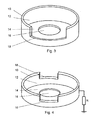
- the insert 10 is designed as a kind of can made of a metallic material, such as stainless steel bleach. That is, it has a cylindrical basic shape and is bounded on one axial side by a flange 14, which extends radially inwardly and leaves a coaxial opening 16 for the drive axis of the rotor 20.
- the cylindrical end face of the flange 14 is in Fig. 1 and Fig. 3 shown with the inner diameter of the Flanschab gleiches 15.
- a franking 18, which is provided on the cylindrical basic shape of the insert 10 away from the flange is, according to Fig. 1 the hose is directed into the interior of the insert 10.
- the roll length of the rolling bed is just under 270 °.
- at least one rolling element must always close the hose and so a rolling length of 180 ° would be sufficient for two rolling elements.
- the flange 14 may also face radially outward, or it may be in addition to that in FIG Fig. 3 shown flange 14 may be provided at the other end of the insert part, a further outwardly directed flange.
- the insert 10 is made of a metallic material and so has the trolley, so the cylindrical inner surface of the insert, an electrically conductive surface.
- the rolling elements can also have an electrically conductive surface and, as a result, corresponding charges are also reduced and / or avoided at the hose rolling element contact.
- an electrically conductive connection may be provided by the rotor 20 with its rollers 24a, 24b to the trolley, such as by a sliding contact on the drive axle of the trolley Rotor 20 which is electrically connected to the insert part 10 (not shown) and so this effect of avoiding the charges is enhanced.
- the entire trolley is made electrically conductive. But there is already a significant reduction of glitches when the trundle bed is provided only in the input and execution area of the tube 30 with conductive and grounded sections. Charges that are on the outside of the hose or corresponding interference pulses can be dissipated through the ground.
- the insert 10 can be inexpensively manufactured in a deep drawing operation with a precise roundness and with a smooth surface of a metal sheet.
- This insert is used in an injection molding tool.
- the insert is molded and forms a positive and firm connection with the overmolded body of the peristaltic pump.
- the peristaltic pump may be integrated into the front panel of the corresponding medical device to be easily accessible to the operator. In this case, the insert is molded in the corresponding front panel.
- the insert can also be a metal foil, which can be inserted annularly into the injection molding tool and molded around.
- the metallic Oberftambae of the rolling bed can also be subsequently applied to a molded plastic molding.
- MID Molded Interconnection Device
- this technology is primarily used for the production of three-dimensional traces for electrical circuits, it is also possible in this way to produce continuous conductive surfaces.
- a suitably coatable plastic is used, which is galvanically provided with a corresponding metal layer. If in a two-component injection molding process this coatable plastic is used exclusively in the area of the rolling bed, then another material can be used for the front of the device.
- a stainless steel foil or stainless steel sheet can be clamped in the cylindrical receptacle and / or glued.
- the insert 10 (see Fig. 3 ) has a franking 18, which according to Fig. 1 both for insertion and removal of the hose is used, so that the roll length, so the pressure surface of the hose in the trundle bed, 270 °.
- an insert according to Fig. 4 can be used, which has two smaller clearances 18 at opposite locations.
- This Insert can be used in a peristaltic pump, in which the tube is introduced on a first side in the cylindrical portion, out there over one and a half rounds and leaves the pump on a second opposite side. Also, the hose can be guided with more revolutions in the pump.
- Fig. 4 schematically shows a resistor R, which is electrically connected between the insert 10 and a potential equalization or in particular a ground.
- This equipotential bonding can also be connected to the rotor 20.
- the resistor R causes a limitation of the leakage current of the interference signal. If a sensitive device is connected to the equipotential bonding or grounding, this prevents interference signals from being passed on to this device via equipotential bonding.
- a hose roller pump has been described in the exemplary embodiment, which uses rollers as rolling or pressure elements.
- the invention is accordingly applicable to peristaltic pumps with spherical rolling elements.
- Such a peristaltic pump is similar to a radial ball bearing, wherein the outer race of the stator is, which has circumferentially a concave recess in which the hose is located, which is successively closed locally by preferably two outwardly pressing balls.
- the drive of the pump takes place directly on the balls, which are comparable to a radial ball bearing guided in a cage.
Landscapes
- Health & Medical Sciences (AREA)
- Engineering & Computer Science (AREA)
- Heart & Thoracic Surgery (AREA)
- Cardiology (AREA)
- Mechanical Engineering (AREA)
- Animal Behavior & Ethology (AREA)
- Public Health (AREA)
- Veterinary Medicine (AREA)
- Anesthesiology (AREA)
- Biomedical Technology (AREA)
- Hematology (AREA)
- Life Sciences & Earth Sciences (AREA)
- General Health & Medical Sciences (AREA)
- Urology & Nephrology (AREA)
- General Engineering & Computer Science (AREA)
- Emergency Medicine (AREA)
- Vascular Medicine (AREA)
- Physics & Mathematics (AREA)
- Electromagnetism (AREA)
- Pulmonology (AREA)
- Reciprocating Pumps (AREA)
- External Artificial Organs (AREA)
- Infusion, Injection, And Reservoir Apparatuses (AREA)
- Structures Of Non-Positive Displacement Pumps (AREA)
Applications Claiming Priority (2)
| Application Number | Priority Date | Filing Date | Title |
|---|---|---|---|
| DE102009046406A DE102009046406B4 (de) | 2009-11-04 | 2009-11-04 | Schlauchpumpe |
| PCT/EP2010/066777 WO2011054890A1 (de) | 2009-11-04 | 2010-11-04 | Schlauchpumpe |
Publications (2)
| Publication Number | Publication Date |
|---|---|
| EP2496279A1 EP2496279A1 (de) | 2012-09-12 |
| EP2496279B1 true EP2496279B1 (de) | 2014-01-22 |
Family
ID=43501602
Family Applications (1)
| Application Number | Title | Priority Date | Filing Date |
|---|---|---|---|
| EP10771784.5A Active EP2496279B1 (de) | 2009-11-04 | 2010-11-04 | Schlauchpumpe |
Country Status (11)
| Country | Link |
|---|---|
| US (1) | US9243625B2 (ja) |
| EP (1) | EP2496279B1 (ja) |
| JP (1) | JP5518206B2 (ja) |
| KR (1) | KR101771753B1 (ja) |
| CN (1) | CN102596281B (ja) |
| AU (1) | AU2010317054B2 (ja) |
| CA (1) | CA2779865C (ja) |
| DE (1) | DE102009046406B4 (ja) |
| EA (1) | EA021639B1 (ja) |
| IN (1) | IN2012DN04859A (ja) |
| WO (1) | WO2011054890A1 (ja) |
Families Citing this family (17)
| Publication number | Priority date | Publication date | Assignee | Title |
|---|---|---|---|---|
| US9746412B2 (en) | 2012-05-30 | 2017-08-29 | Iris International, Inc. | Flow cytometer |
| US9504522B2 (en) * | 2013-06-25 | 2016-11-29 | Biosense Webster (Israel) Ltd. | Electrocardiogram noise reduction |
| US10265025B2 (en) * | 2013-06-25 | 2019-04-23 | Biosense Webster (Israel) Ltd. | Electrocardiogram noise reduction |
| KR101443859B1 (ko) * | 2013-10-30 | 2014-09-24 | 김용배 | 호스식 약품 정량 이송펌프구조체 |
| KR101598053B1 (ko) * | 2014-03-13 | 2016-02-26 | 주식회사 베스테크 | 줄기세포 분리기의 연동펌프장치 |
| DE102015102658A1 (de) * | 2015-02-25 | 2016-08-25 | B. Braun Avitum Ag | Gehäusefrontintegrierte Blutpumpe |
| WO2017129193A1 (en) * | 2016-01-25 | 2017-08-03 | Fluisense Aps | Micro dosage peristaltic pump for micro dosage of fluid |
| DE102016005467A1 (de) * | 2016-05-06 | 2017-11-09 | Fresenius Medical Care Deutschland Gmbh | Medizinische Behandlungsvorrichtung und Schlauchset für eine medizinische Behandlungsvorrichtung sowie Verfahren zur Überwachung einer peristaltischen Schlauchpumpe |
| US10690127B2 (en) * | 2016-08-30 | 2020-06-23 | Alcon Inc. | Handheld ophthalmic probe with peristaltic pump and associated devices, systems, and methods |
| CN109890433A (zh) * | 2016-11-02 | 2019-06-14 | 圣犹达医疗用品心脏病学部门有限公司 | 用于蠕动泵的接触管 |
| KR101874808B1 (ko) | 2017-07-21 | 2018-08-06 | 엘븐트리 주식회사 | 무맥동 연동 펌프 |
| CN107829919B (zh) * | 2017-11-09 | 2024-01-30 | 四川君汇科技有限公司 | 滚珠式蠕动泵及泵管安装方法 |
| CN107725343B (zh) * | 2017-11-09 | 2024-01-30 | 四川君汇科技有限公司 | 组合式蠕动泵及组合定位安装方法 |
| CN113710943A (zh) * | 2019-04-30 | 2021-11-26 | 美国圣戈班性能塑料公司 | 耗散蠕动泵管路 |
| CN110307362B (zh) * | 2019-07-01 | 2020-11-03 | 陕西理工大学 | 一种流路调节切换装置及方法 |
| EP4013964A4 (en) * | 2019-08-28 | 2023-12-20 | ReelReactor, LLC | PERISTALTIC FLUID ISOLATION PUMP |
| JP7405585B2 (ja) | 2019-12-04 | 2023-12-26 | テルモ株式会社 | 医療用ポンプモジュール及び医療用ポンプ |
Family Cites Families (22)
| Publication number | Priority date | Publication date | Assignee | Title |
|---|---|---|---|---|
| DE36633C (de) | G. MAHLOW in Stettin | Spiegelreflektorhalter an Klavieren | ||
| US3580893A (en) | 1966-10-25 | 1971-05-25 | Gulf Research Development Co | Process for the preparation of cyclic acid anhydrides |
| US3580983A (en) * | 1969-12-03 | 1971-05-25 | Nat Catheter Corp | Conductive line tube |
| US4277226A (en) * | 1979-03-09 | 1981-07-07 | Avi, Inc. | IV Pump with empty supply reservoir and occlusion detector |
| JPS56113083A (en) * | 1980-02-12 | 1981-09-05 | Terumo Corp | Choke detection method and device for peristaltic liquid pump |
| JPH0311254Y2 (ja) * | 1987-10-23 | 1991-03-19 | ||
| JP2529404B2 (ja) | 1989-08-02 | 1996-08-28 | 松下電器産業株式会社 | マスキング係数決定装置 |
| JP2510135Y2 (ja) * | 1989-10-31 | 1996-09-11 | 株式会社島津製作所 | ペリスタポンプ |
| US5127907A (en) * | 1990-12-06 | 1992-07-07 | Abbott Laboratories | System for eliminating or reducing static electricity in infusion pumping systems |
| US5324180A (en) * | 1992-09-04 | 1994-06-28 | Allergan, Inc. | Surgical instrument with drawer loading cassette system |
| US6533747B1 (en) * | 2000-05-23 | 2003-03-18 | Chf Solutions, Inc. | Extracorporeal circuit for peripheral vein fluid removal |
| MXPA04000801A (es) * | 2003-01-29 | 2005-06-17 | Innovamedica S A De C V | Anastomosis auricular-arterial de bajo flujo para revascularizacion del miocardio auxiliada por bomba sin derivacion cardiopulmonar. |
| US7074021B2 (en) * | 2003-05-12 | 2006-07-11 | Byrne Medical, Inc. | Cartridge to be used with a peristaltic pump |
| ITMO20030165A1 (it) * | 2003-06-04 | 2004-12-05 | Gambro Lundia Ab | Giunto per linee di trasporto fluido ad uso medicale. |
| ES2376429T3 (es) | 2003-06-05 | 2012-03-13 | Fluor Corporation | Configuración y procedimiento de regasificación de gas natural licuado. |
| US7001153B2 (en) | 2003-06-30 | 2006-02-21 | Blue-White Industries | Peristaltic injector pump leak monitor |
| US7223079B2 (en) * | 2003-07-28 | 2007-05-29 | The Coca-Cola Company | Quick loading peristaltic pump |
| EA013552B1 (ru) * | 2004-05-14 | 2010-06-30 | Фрезениус Медикел Кэар Дойчланд Гмбх | Роторный насос |
| AU2006295394A1 (en) * | 2005-09-23 | 2007-04-05 | Medtronic, Inc. | Tubing holding device for roller pumps |
| DE102006042646B4 (de) * | 2006-09-12 | 2008-11-20 | Fresenius Medical Care Deutschland Gmbh | Vorrichtung und Verfahren zur Überwachung eines Zugangs zu einem Patienten, insbesondere eines Gefäßzugangs bei einer extrakorporalen Blutbehandlung |
| ATE496645T1 (de) * | 2007-10-03 | 2011-02-15 | Gambro Lundia Ab | Medizinisches gerät |
| JP5094507B2 (ja) | 2008-03-28 | 2012-12-12 | 富士フイルム株式会社 | チューブポンプ、インクジェット記録装置、インクジェット記録方法及び印刷物 |
-
2009
- 2009-11-04 DE DE102009046406A patent/DE102009046406B4/de not_active Expired - Fee Related
-
2010
- 2010-11-04 US US13/505,616 patent/US9243625B2/en active Active
- 2010-11-04 IN IN4859DEN2012 patent/IN2012DN04859A/en unknown
- 2010-11-04 CN CN201080049896.2A patent/CN102596281B/zh not_active Expired - Fee Related
- 2010-11-04 EA EA201290282A patent/EA021639B1/ru not_active IP Right Cessation
- 2010-11-04 AU AU2010317054A patent/AU2010317054B2/en not_active Ceased
- 2010-11-04 JP JP2012535878A patent/JP5518206B2/ja not_active Expired - Fee Related
- 2010-11-04 KR KR1020127014396A patent/KR101771753B1/ko active IP Right Grant
- 2010-11-04 CA CA2779865A patent/CA2779865C/en not_active Expired - Fee Related
- 2010-11-04 EP EP10771784.5A patent/EP2496279B1/de active Active
- 2010-11-04 WO PCT/EP2010/066777 patent/WO2011054890A1/de active Application Filing
Also Published As
| Publication number | Publication date |
|---|---|
| JP5518206B2 (ja) | 2014-06-11 |
| CN102596281A (zh) | 2012-07-18 |
| IN2012DN04859A (ja) | 2015-09-25 |
| JP2013509899A (ja) | 2013-03-21 |
| CA2779865C (en) | 2018-02-27 |
| KR20120081621A (ko) | 2012-07-19 |
| AU2010317054A1 (en) | 2012-06-21 |
| US9243625B2 (en) | 2016-01-26 |
| CA2779865A1 (en) | 2011-05-12 |
| KR101771753B1 (ko) | 2017-08-25 |
| DE102009046406B4 (de) | 2012-04-26 |
| EP2496279A1 (de) | 2012-09-12 |
| DE102009046406A1 (de) | 2011-05-05 |
| EA021639B1 (ru) | 2015-07-30 |
| AU2010317054B2 (en) | 2015-02-05 |
| CN102596281B (zh) | 2015-05-13 |
| WO2011054890A1 (de) | 2011-05-12 |
| US20120282126A1 (en) | 2012-11-08 |
| EA201290282A1 (ru) | 2012-11-30 |
Similar Documents
| Publication | Publication Date | Title |
|---|---|---|
| EP2496279B1 (de) | Schlauchpumpe | |
| EP0904630A1 (de) | Verfahren zur herstellung eines mikromotors | |
| EP2814534A1 (de) | Intravasale blutpumpe | |
| EP2682607B1 (de) | Schlauchrollenpumpe mit schwenkbarer Schlauchaufnahme, und medizinisches Gerät für extrakorporale Blutbehandlung | |
| EP3642634B1 (de) | Anordnung eines drehimpulsgebers und einer klemmhülse zur erfassung einer drehzahl eines rotors | |
| EP2990647B1 (de) | Schlauchpumpe | |
| DE102011051264A1 (de) | Motorhalterung und Stellantrieb mit Motor | |
| DE3040143A1 (de) | Vorrichtung mit fliehgewichtsbremse, insbesondere zum selbsttaetigen aufwickeln einer anschlussleitung | |
| EP3061474B1 (de) | Gehäusefrontintegrierte blutpumpe | |
| EP1952509B1 (de) | Motor-pumpen-aggregat mit verbesserter dichtung | |
| EP3281653B1 (de) | Peristaltikpumpe mit modularem gehäuse | |
| EP4034845A1 (de) | Magnetisch-induktives durchflussmessgerät | |
| DE102009052180A1 (de) | Hochvakuumpumpe | |
| DE102008002761A1 (de) | Schlauchpumpe zur Förderung von Fluiden | |
| DE19962498A1 (de) | Pumpenkörper für eine medizinische Zahnradpumpe | |
| DE202009001948U1 (de) | Elektrisch leitfähige Rolle | |
| AT521270B1 (de) | Abdichtvorrichtung | |
| DE202009000100U1 (de) | Elektrisch leitfähige Rolle | |
| WO2021053077A1 (de) | Elektromotorisch angetriebenes aggregat für ein fahrzeug | |
| DE102014119455A1 (de) | Gehäuse für ein Feldgerät der Automatisierungstechnik | |
| DE102021112365A1 (de) | Lageranordnung mit in Kunststoffträger integrierter Sensoreinheit | |
| EP2745014B1 (de) | Motor-pumpen-kombination | |
| DE102017105248A1 (de) | Vakuumpumpe mit Platine als Vakuumdurchführung | |
| EP2363092A1 (de) | Medizinische, insbesondere dentale, Behandlungsvorrichtung mit einem Dichtelement | |
| DE202015102189U1 (de) | Injektor zur Injektion von Kontrastmitteln |
Legal Events
| Date | Code | Title | Description |
|---|---|---|---|
| PUAI | Public reference made under article 153(3) epc to a published international application that has entered the european phase |
Free format text: ORIGINAL CODE: 0009012 |
|
| 17P | Request for examination filed |
Effective date: 20120604 |
|
| AK | Designated contracting states |
Kind code of ref document: A1 Designated state(s): AL AT BE BG CH CY CZ DE DK EE ES FI FR GB GR HR HU IE IS IT LI LT LU LV MC MK MT NL NO PL PT RO RS SE SI SK SM TR |
|
| DAX | Request for extension of the european patent (deleted) | ||
| GRAP | Despatch of communication of intention to grant a patent |
Free format text: ORIGINAL CODE: EPIDOSNIGR1 |
|
| INTG | Intention to grant announced |
Effective date: 20130813 |
|
| GRAS | Grant fee paid |
Free format text: ORIGINAL CODE: EPIDOSNIGR3 |
|
| GRAA | (expected) grant |
Free format text: ORIGINAL CODE: 0009210 |
|
| AK | Designated contracting states |
Kind code of ref document: B1 Designated state(s): AL AT BE BG CH CY CZ DE DK EE ES FI FR GB GR HR HU IE IS IT LI LT LU LV MC MK MT NL NO PL PT RO RS SE SI SK SM TR |
|
| REG | Reference to a national code |
Ref country code: GB Ref legal event code: FG4D Free format text: NOT ENGLISH |
|
| REG | Reference to a national code |
Ref country code: CH Ref legal event code: EP |
|
| REG | Reference to a national code |
Ref country code: AT Ref legal event code: REF Ref document number: 650463 Country of ref document: AT Kind code of ref document: T Effective date: 20140215 |
|
| REG | Reference to a national code |
Ref country code: IE Ref legal event code: FG4D Free format text: LANGUAGE OF EP DOCUMENT: GERMAN |
|
| REG | Reference to a national code |
Ref country code: DE Ref legal event code: R096 Ref document number: 502010006029 Country of ref document: DE Effective date: 20140306 |
|
| REG | Reference to a national code |
Ref country code: SE Ref legal event code: TRGR |
|
| REG | Reference to a national code |
Ref country code: NL Ref legal event code: VDEP Effective date: 20140122 |
|
| REG | Reference to a national code |
Ref country code: LT Ref legal event code: MG4D |
|
| PG25 | Lapsed in a contracting state [announced via postgrant information from national office to epo] |
Ref country code: NO Free format text: LAPSE BECAUSE OF FAILURE TO SUBMIT A TRANSLATION OF THE DESCRIPTION OR TO PAY THE FEE WITHIN THE PRESCRIBED TIME-LIMIT Effective date: 20140422 Ref country code: LT Free format text: LAPSE BECAUSE OF FAILURE TO SUBMIT A TRANSLATION OF THE DESCRIPTION OR TO PAY THE FEE WITHIN THE PRESCRIBED TIME-LIMIT Effective date: 20140122 Ref country code: IS Free format text: LAPSE BECAUSE OF FAILURE TO SUBMIT A TRANSLATION OF THE DESCRIPTION OR TO PAY THE FEE WITHIN THE PRESCRIBED TIME-LIMIT Effective date: 20140522 |
|
| PG25 | Lapsed in a contracting state [announced via postgrant information from national office to epo] |
Ref country code: NL Free format text: LAPSE BECAUSE OF FAILURE TO SUBMIT A TRANSLATION OF THE DESCRIPTION OR TO PAY THE FEE WITHIN THE PRESCRIBED TIME-LIMIT Effective date: 20140122 Ref country code: PT Free format text: LAPSE BECAUSE OF FAILURE TO SUBMIT A TRANSLATION OF THE DESCRIPTION OR TO PAY THE FEE WITHIN THE PRESCRIBED TIME-LIMIT Effective date: 20140522 Ref country code: FI Free format text: LAPSE BECAUSE OF FAILURE TO SUBMIT A TRANSLATION OF THE DESCRIPTION OR TO PAY THE FEE WITHIN THE PRESCRIBED TIME-LIMIT Effective date: 20140122 Ref country code: ES Free format text: LAPSE BECAUSE OF FAILURE TO SUBMIT A TRANSLATION OF THE DESCRIPTION OR TO PAY THE FEE WITHIN THE PRESCRIBED TIME-LIMIT Effective date: 20140122 Ref country code: CY Free format text: LAPSE BECAUSE OF FAILURE TO SUBMIT A TRANSLATION OF THE DESCRIPTION OR TO PAY THE FEE WITHIN THE PRESCRIBED TIME-LIMIT Effective date: 20140122 |
|
| PG25 | Lapsed in a contracting state [announced via postgrant information from national office to epo] |
Ref country code: RS Free format text: LAPSE BECAUSE OF FAILURE TO SUBMIT A TRANSLATION OF THE DESCRIPTION OR TO PAY THE FEE WITHIN THE PRESCRIBED TIME-LIMIT Effective date: 20140122 Ref country code: HR Free format text: LAPSE BECAUSE OF FAILURE TO SUBMIT A TRANSLATION OF THE DESCRIPTION OR TO PAY THE FEE WITHIN THE PRESCRIBED TIME-LIMIT Effective date: 20140122 Ref country code: LV Free format text: LAPSE BECAUSE OF FAILURE TO SUBMIT A TRANSLATION OF THE DESCRIPTION OR TO PAY THE FEE WITHIN THE PRESCRIBED TIME-LIMIT Effective date: 20140122 |
|
| REG | Reference to a national code |
Ref country code: DE Ref legal event code: R097 Ref document number: 502010006029 Country of ref document: DE |
|
| PG25 | Lapsed in a contracting state [announced via postgrant information from national office to epo] |
Ref country code: RO Free format text: LAPSE BECAUSE OF FAILURE TO SUBMIT A TRANSLATION OF THE DESCRIPTION OR TO PAY THE FEE WITHIN THE PRESCRIBED TIME-LIMIT Effective date: 20140122 Ref country code: EE Free format text: LAPSE BECAUSE OF FAILURE TO SUBMIT A TRANSLATION OF THE DESCRIPTION OR TO PAY THE FEE WITHIN THE PRESCRIBED TIME-LIMIT Effective date: 20140122 Ref country code: CZ Free format text: LAPSE BECAUSE OF FAILURE TO SUBMIT A TRANSLATION OF THE DESCRIPTION OR TO PAY THE FEE WITHIN THE PRESCRIBED TIME-LIMIT Effective date: 20140122 Ref country code: DK Free format text: LAPSE BECAUSE OF FAILURE TO SUBMIT A TRANSLATION OF THE DESCRIPTION OR TO PAY THE FEE WITHIN THE PRESCRIBED TIME-LIMIT Effective date: 20140122 |
|
| PG25 | Lapsed in a contracting state [announced via postgrant information from national office to epo] |
Ref country code: SK Free format text: LAPSE BECAUSE OF FAILURE TO SUBMIT A TRANSLATION OF THE DESCRIPTION OR TO PAY THE FEE WITHIN THE PRESCRIBED TIME-LIMIT Effective date: 20140122 Ref country code: PL Free format text: LAPSE BECAUSE OF FAILURE TO SUBMIT A TRANSLATION OF THE DESCRIPTION OR TO PAY THE FEE WITHIN THE PRESCRIBED TIME-LIMIT Effective date: 20140122 |
|
| PLBE | No opposition filed within time limit |
Free format text: ORIGINAL CODE: 0009261 |
|
| STAA | Information on the status of an ep patent application or granted ep patent |
Free format text: STATUS: NO OPPOSITION FILED WITHIN TIME LIMIT |
|
| 26N | No opposition filed |
Effective date: 20141023 |
|
| REG | Reference to a national code |
Ref country code: DE Ref legal event code: R097 Ref document number: 502010006029 Country of ref document: DE Effective date: 20141023 |
|
| PG25 | Lapsed in a contracting state [announced via postgrant information from national office to epo] |
Ref country code: SI Free format text: LAPSE BECAUSE OF FAILURE TO SUBMIT A TRANSLATION OF THE DESCRIPTION OR TO PAY THE FEE WITHIN THE PRESCRIBED TIME-LIMIT Effective date: 20140122 |
|
| PG25 | Lapsed in a contracting state [announced via postgrant information from national office to epo] |
Ref country code: BE Free format text: LAPSE BECAUSE OF NON-PAYMENT OF DUE FEES Effective date: 20141130 Ref country code: MC Free format text: LAPSE BECAUSE OF FAILURE TO SUBMIT A TRANSLATION OF THE DESCRIPTION OR TO PAY THE FEE WITHIN THE PRESCRIBED TIME-LIMIT Effective date: 20140122 Ref country code: LU Free format text: LAPSE BECAUSE OF FAILURE TO SUBMIT A TRANSLATION OF THE DESCRIPTION OR TO PAY THE FEE WITHIN THE PRESCRIBED TIME-LIMIT Effective date: 20141104 |
|
| REG | Reference to a national code |
Ref country code: CH Ref legal event code: PL |
|
| PG25 | Lapsed in a contracting state [announced via postgrant information from national office to epo] |
Ref country code: LI Free format text: LAPSE BECAUSE OF NON-PAYMENT OF DUE FEES Effective date: 20141130 Ref country code: CH Free format text: LAPSE BECAUSE OF NON-PAYMENT OF DUE FEES Effective date: 20141130 |
|
| REG | Reference to a national code |
Ref country code: IE Ref legal event code: MM4A |
|
| REG | Reference to a national code |
Ref country code: FR Ref legal event code: PLFP Year of fee payment: 6 |
|
| PG25 | Lapsed in a contracting state [announced via postgrant information from national office to epo] |
Ref country code: IE Free format text: LAPSE BECAUSE OF NON-PAYMENT OF DUE FEES Effective date: 20141104 |
|
| PG25 | Lapsed in a contracting state [announced via postgrant information from national office to epo] |
Ref country code: SM Free format text: LAPSE BECAUSE OF FAILURE TO SUBMIT A TRANSLATION OF THE DESCRIPTION OR TO PAY THE FEE WITHIN THE PRESCRIBED TIME-LIMIT Effective date: 20140122 |
|
| PG25 | Lapsed in a contracting state [announced via postgrant information from national office to epo] |
Ref country code: GR Free format text: LAPSE BECAUSE OF FAILURE TO SUBMIT A TRANSLATION OF THE DESCRIPTION OR TO PAY THE FEE WITHIN THE PRESCRIBED TIME-LIMIT Effective date: 20140423 Ref country code: BG Free format text: LAPSE BECAUSE OF FAILURE TO SUBMIT A TRANSLATION OF THE DESCRIPTION OR TO PAY THE FEE WITHIN THE PRESCRIBED TIME-LIMIT Effective date: 20140122 |
|
| PG25 | Lapsed in a contracting state [announced via postgrant information from national office to epo] |
Ref country code: MT Free format text: LAPSE BECAUSE OF FAILURE TO SUBMIT A TRANSLATION OF THE DESCRIPTION OR TO PAY THE FEE WITHIN THE PRESCRIBED TIME-LIMIT Effective date: 20140122 Ref country code: HU Free format text: LAPSE BECAUSE OF FAILURE TO SUBMIT A TRANSLATION OF THE DESCRIPTION OR TO PAY THE FEE WITHIN THE PRESCRIBED TIME-LIMIT; INVALID AB INITIO Effective date: 20101104 Ref country code: TR Free format text: LAPSE BECAUSE OF FAILURE TO SUBMIT A TRANSLATION OF THE DESCRIPTION OR TO PAY THE FEE WITHIN THE PRESCRIBED TIME-LIMIT Effective date: 20140122 |
|
| REG | Reference to a national code |
Ref country code: FR Ref legal event code: PLFP Year of fee payment: 7 |
|
| REG | Reference to a national code |
Ref country code: AT Ref legal event code: MM01 Ref document number: 650463 Country of ref document: AT Kind code of ref document: T Effective date: 20151104 |
|
| PG25 | Lapsed in a contracting state [announced via postgrant information from national office to epo] |
Ref country code: AT Free format text: LAPSE BECAUSE OF NON-PAYMENT OF DUE FEES Effective date: 20151104 |
|
| REG | Reference to a national code |
Ref country code: FR Ref legal event code: PLFP Year of fee payment: 8 |
|
| PG25 | Lapsed in a contracting state [announced via postgrant information from national office to epo] |
Ref country code: MK Free format text: LAPSE BECAUSE OF FAILURE TO SUBMIT A TRANSLATION OF THE DESCRIPTION OR TO PAY THE FEE WITHIN THE PRESCRIBED TIME-LIMIT Effective date: 20140122 |
|
| REG | Reference to a national code |
Ref country code: FR Ref legal event code: PLFP Year of fee payment: 9 |
|
| PG25 | Lapsed in a contracting state [announced via postgrant information from national office to epo] |
Ref country code: AL Free format text: LAPSE BECAUSE OF FAILURE TO SUBMIT A TRANSLATION OF THE DESCRIPTION OR TO PAY THE FEE WITHIN THE PRESCRIBED TIME-LIMIT Effective date: 20140122 |
|
| REG | Reference to a national code |
Ref country code: DE Ref legal event code: R079 Ref document number: 502010006029 Country of ref document: DE Free format text: PREVIOUS MAIN CLASS: A61M0001100000 Ipc: A61M0060000000 |
|
| PGFP | Annual fee paid to national office [announced via postgrant information from national office to epo] |
Ref country code: SE Payment date: 20201026 Year of fee payment: 11 Ref country code: IT Payment date: 20201021 Year of fee payment: 11 Ref country code: GB Payment date: 20201021 Year of fee payment: 11 Ref country code: FR Payment date: 20201021 Year of fee payment: 11 |
|
| GBPC | Gb: european patent ceased through non-payment of renewal fee |
Effective date: 20211104 |
|
| PG25 | Lapsed in a contracting state [announced via postgrant information from national office to epo] |
Ref country code: SE Free format text: LAPSE BECAUSE OF NON-PAYMENT OF DUE FEES Effective date: 20211105 |
|
| PG25 | Lapsed in a contracting state [announced via postgrant information from national office to epo] |
Ref country code: GB Free format text: LAPSE BECAUSE OF NON-PAYMENT OF DUE FEES Effective date: 20211104 |
|
| PG25 | Lapsed in a contracting state [announced via postgrant information from national office to epo] |
Ref country code: FR Free format text: LAPSE BECAUSE OF NON-PAYMENT OF DUE FEES Effective date: 20211130 |
|
| PG25 | Lapsed in a contracting state [announced via postgrant information from national office to epo] |
Ref country code: IT Free format text: LAPSE BECAUSE OF NON-PAYMENT OF DUE FEES Effective date: 20211104 |
|
| P01 | Opt-out of the competence of the unified patent court (upc) registered |
Effective date: 20230602 |
|
| PGFP | Annual fee paid to national office [announced via postgrant information from national office to epo] |
Ref country code: DE Payment date: 20231019 Year of fee payment: 14 |