EP2496279B1 - Schlauchpumpe - Google Patents
Schlauchpumpe Download PDFInfo
- Publication number
- EP2496279B1 EP2496279B1 EP10771784.5A EP10771784A EP2496279B1 EP 2496279 B1 EP2496279 B1 EP 2496279B1 EP 10771784 A EP10771784 A EP 10771784A EP 2496279 B1 EP2496279 B1 EP 2496279B1
- Authority
- EP
- European Patent Office
- Prior art keywords
- hose
- hose pump
- electrically conducting
- rolling
- rolling bed
- Prior art date
- Legal status (The legal status is an assumption and is not a legal conclusion. Google has not performed a legal analysis and makes no representation as to the accuracy of the status listed.)
- Active
Links
Images

Classifications
-
- F—MECHANICAL ENGINEERING; LIGHTING; HEATING; WEAPONS; BLASTING
- F04—POSITIVE - DISPLACEMENT MACHINES FOR LIQUIDS; PUMPS FOR LIQUIDS OR ELASTIC FLUIDS
- F04B—POSITIVE-DISPLACEMENT MACHINES FOR LIQUIDS; PUMPS
- F04B43/00—Machines, pumps, or pumping installations having flexible working members
- F04B43/12—Machines, pumps, or pumping installations having flexible working members having peristaltic action
- F04B43/1253—Machines, pumps, or pumping installations having flexible working members having peristaltic action by using two or more rollers as squeezing elements, the rollers moving on an arc of a circle during squeezing
- F04B43/1261—Machines, pumps, or pumping installations having flexible working members having peristaltic action by using two or more rollers as squeezing elements, the rollers moving on an arc of a circle during squeezing the rollers being placed at the outside of the tubular flexible member
-
- A—HUMAN NECESSITIES
- A61—MEDICAL OR VETERINARY SCIENCE; HYGIENE
- A61M—DEVICES FOR INTRODUCING MEDIA INTO, OR ONTO, THE BODY; DEVICES FOR TRANSDUCING BODY MEDIA OR FOR TAKING MEDIA FROM THE BODY; DEVICES FOR PRODUCING OR ENDING SLEEP OR STUPOR
- A61M1/00—Suction or pumping devices for medical purposes; Devices for carrying-off, for treatment of, or for carrying-over, body-liquids; Drainage systems
- A61M1/14—Dialysis systems; Artificial kidneys; Blood oxygenators ; Reciprocating systems for treatment of body fluids, e.g. single needle systems for hemofiltration or pheresis
- A61M1/16—Dialysis systems; Artificial kidneys; Blood oxygenators ; Reciprocating systems for treatment of body fluids, e.g. single needle systems for hemofiltration or pheresis with membranes
-
- A—HUMAN NECESSITIES
- A61—MEDICAL OR VETERINARY SCIENCE; HYGIENE
- A61M—DEVICES FOR INTRODUCING MEDIA INTO, OR ONTO, THE BODY; DEVICES FOR TRANSDUCING BODY MEDIA OR FOR TAKING MEDIA FROM THE BODY; DEVICES FOR PRODUCING OR ENDING SLEEP OR STUPOR
- A61M60/00—Blood pumps; Devices for mechanical circulatory actuation; Balloon pumps for circulatory assistance
- A61M60/10—Location thereof with respect to the patient's body
- A61M60/104—Extracorporeal pumps, i.e. the blood being pumped outside the patient's body
- A61M60/109—Extracorporeal pumps, i.e. the blood being pumped outside the patient's body incorporated within extracorporeal blood circuits or systems
- A61M60/113—Extracorporeal pumps, i.e. the blood being pumped outside the patient's body incorporated within extracorporeal blood circuits or systems in other functional devices, e.g. dialysers or heart-lung machines
-
- A—HUMAN NECESSITIES
- A61—MEDICAL OR VETERINARY SCIENCE; HYGIENE
- A61M—DEVICES FOR INTRODUCING MEDIA INTO, OR ONTO, THE BODY; DEVICES FOR TRANSDUCING BODY MEDIA OR FOR TAKING MEDIA FROM THE BODY; DEVICES FOR PRODUCING OR ENDING SLEEP OR STUPOR
- A61M60/00—Blood pumps; Devices for mechanical circulatory actuation; Balloon pumps for circulatory assistance
- A61M60/20—Type thereof
- A61M60/247—Positive displacement blood pumps
- A61M60/253—Positive displacement blood pumps including a displacement member directly acting on the blood
- A61M60/268—Positive displacement blood pumps including a displacement member directly acting on the blood the displacement member being flexible, e.g. membranes, diaphragms or bladders
- A61M60/279—Peristaltic pumps, e.g. roller pumps
-
- A—HUMAN NECESSITIES
- A61—MEDICAL OR VETERINARY SCIENCE; HYGIENE
- A61M—DEVICES FOR INTRODUCING MEDIA INTO, OR ONTO, THE BODY; DEVICES FOR TRANSDUCING BODY MEDIA OR FOR TAKING MEDIA FROM THE BODY; DEVICES FOR PRODUCING OR ENDING SLEEP OR STUPOR
- A61M60/00—Blood pumps; Devices for mechanical circulatory actuation; Balloon pumps for circulatory assistance
- A61M60/30—Medical purposes thereof other than the enhancement of the cardiac output
- A61M60/36—Medical purposes thereof other than the enhancement of the cardiac output for specific blood treatment; for specific therapy
- A61M60/37—Haemodialysis, haemofiltration or diafiltration
-
- A—HUMAN NECESSITIES
- A61—MEDICAL OR VETERINARY SCIENCE; HYGIENE
- A61M—DEVICES FOR INTRODUCING MEDIA INTO, OR ONTO, THE BODY; DEVICES FOR TRANSDUCING BODY MEDIA OR FOR TAKING MEDIA FROM THE BODY; DEVICES FOR PRODUCING OR ENDING SLEEP OR STUPOR
- A61M60/00—Blood pumps; Devices for mechanical circulatory actuation; Balloon pumps for circulatory assistance
- A61M60/30—Medical purposes thereof other than the enhancement of the cardiac output
- A61M60/39—Medical purposes thereof other than the enhancement of the cardiac output for blood transfusion
-
- A—HUMAN NECESSITIES
- A61—MEDICAL OR VETERINARY SCIENCE; HYGIENE
- A61M—DEVICES FOR INTRODUCING MEDIA INTO, OR ONTO, THE BODY; DEVICES FOR TRANSDUCING BODY MEDIA OR FOR TAKING MEDIA FROM THE BODY; DEVICES FOR PRODUCING OR ENDING SLEEP OR STUPOR
- A61M60/00—Blood pumps; Devices for mechanical circulatory actuation; Balloon pumps for circulatory assistance
- A61M60/40—Details relating to driving
- A61M60/424—Details relating to driving for positive displacement blood pumps
- A61M60/457—Details relating to driving for positive displacement blood pumps the force acting on the blood contacting member being magnetic
- A61M60/462—Electromagnetic force
-
- A—HUMAN NECESSITIES
- A61—MEDICAL OR VETERINARY SCIENCE; HYGIENE
- A61M—DEVICES FOR INTRODUCING MEDIA INTO, OR ONTO, THE BODY; DEVICES FOR TRANSDUCING BODY MEDIA OR FOR TAKING MEDIA FROM THE BODY; DEVICES FOR PRODUCING OR ENDING SLEEP OR STUPOR
- A61M60/00—Blood pumps; Devices for mechanical circulatory actuation; Balloon pumps for circulatory assistance
- A61M60/80—Constructional details other than related to driving
- A61M60/835—Constructional details other than related to driving of positive displacement blood pumps
-
- F—MECHANICAL ENGINEERING; LIGHTING; HEATING; WEAPONS; BLASTING
- F04—POSITIVE - DISPLACEMENT MACHINES FOR LIQUIDS; PUMPS FOR LIQUIDS OR ELASTIC FLUIDS
- F04B—POSITIVE-DISPLACEMENT MACHINES FOR LIQUIDS; PUMPS
- F04B43/00—Machines, pumps, or pumping installations having flexible working members
- F04B43/08—Machines, pumps, or pumping installations having flexible working members having tubular flexible members
- F04B43/082—Machines, pumps, or pumping installations having flexible working members having tubular flexible members the tubular flexible member being pressed against a wall by a number of elements, each having an alternating movement in a direction perpendicular to the axes of the tubular member and each having its own driving mechanism
-
- F—MECHANICAL ENGINEERING; LIGHTING; HEATING; WEAPONS; BLASTING
- F04—POSITIVE - DISPLACEMENT MACHINES FOR LIQUIDS; PUMPS FOR LIQUIDS OR ELASTIC FLUIDS
- F04B—POSITIVE-DISPLACEMENT MACHINES FOR LIQUIDS; PUMPS
- F04B43/00—Machines, pumps, or pumping installations having flexible working members
- F04B43/12—Machines, pumps, or pumping installations having flexible working members having peristaltic action
- F04B43/123—Machines, pumps, or pumping installations having flexible working members having peristaltic action using an excenter as the squeezing element
Definitions
- the invention relates to a peristaltic pump according to the preamble of claim 1.
- peristaltic pumps are used to deliver extra-corporeal fluids or to provide them precisely to volume.
- An application for peristaltic pumps can be found in dialysis machines, in which dialysate of the dialysate, dialysis and / or blood must be pumped.
- a peristaltic pump In a peristaltic pump, a flexible tube is placed along a cylindrical inner diameter and locally closed or occluded by radially outwardly acting pressure rollers and by the movement of the driven rollers along the tube is closed place displaced and so realized the fluid delivery.
- An advantage of peristaltic pumps lies in the relatively good metering. Since only the tube with the pumped fluid comes into contact, a peristaltic pump can be quickly and inexpensively cleaned by replacing the hose.
- the rollers in the area of execution of the hose from the hose pump completely lift off from the hose.
- electrostatic charges accumulated on the reel can be transferred to the hose and so on cause corresponding glitch.
- These charges lead to an electrostatic charge of the hose and in particular its outer surface.
- the charge separation is in fact effected according to the triboelectric effect in that different materials have different electron affinity and in the separation of corresponding materials, the electrons can not move freely enough so as to effect a charge balance.
- an arterial-arterial shunt for pump-assisted myocardial revascularization without a cardiopulmonary bypass, which securely receives at each end a short section of cardiopulmonary bypass tube, with a ventilated cannula adapter.
- Object of the present invention is to avoid disturbing influences of electrostatic charges or electrical impulses from a peristaltic pump to electronic devices or at least reduce.
- a peristaltic pump for use in medical technology, with a stator and a rotor, wherein the stator has a trolley, which corresponds to the contact area to a recorded tube and rolling elements are provided on the rotor, which are suitable between the trolley and To close the rolling elements recorded hose.
- the trolley has at least partially an electrically conductive surface for reducing and / or avoiding electrostatic charging of the hose.
- the rolling elements may be rollers or balls and the trolley may also have several separate areas of the conductive surface.
- This embodiment eliminates the need for additional user-visible devices on the peristaltic pump and / or tubing system to prevent electrostatic charging.
- the operator does not have to carry out any additional upgrade steps and has an unchanged visual impression of the peristaltic pump and the medical device in which the peristaltic pump can be integrated.
- an equipotential bonding in particular in the form of a grounding, is provided on the electrically conductive surface.
- This potential equalization can be done by sensitive electronic devices, which are in the vicinity of the peristaltic pump and could be disturbed, e.g. be brought by an electrical conductor to the same electrical potential as the peristaltic pump and in particular its trundle bed.
- a potential equalization can be created by grounding in the electrical supply network, which allows a free charge balance and thus prevents charging of the hose surface or at least effectively reduced.
- a preferably provided between the equipotential bonding and the electrically conductive surface electrical resistance limits the leakage current and thus prevents a transmission of interference signals by means of grounding to other devices connected there.
- the rolling elements preferably also have an electrically conductive surface, which is the lateral surface in the case of cylindrical rollers, and there is an electrically conductive contact with the electrically conductive surface of the rolling bed of these surfaces.
- an electrically conductive surface which is the lateral surface in the case of cylindrical rollers, and there is an electrically conductive contact with the electrically conductive surface of the rolling bed of these surfaces.
- the complete trolley has a continuous electrically conductive surface.
- the trolley bed can have only partially, ie in particular sections, a conductive surface, but a corresponding continuous conductive surface improves the charge balance. It is advantageous, in particular, that this already prevents (or at least reduces) the formation of electrostatic charges, which is significantly more effective than dissipating or compensating any charges that may have occurred. This also ensures that no heels and / or unevenness of the rolling bed arise, which can worsen the rolling of the rolling elements and thus the pumping action and can adversely affect the life of the hose.
- the peristaltic pump can be designed as a hose roller pump, ie the trolley has a cylindrical inwardly directed surface and the rolling elements are designed as rollers.
- Hose roller pumps are inexpensive to manufacture and have good properties accurate metering.
- the peristaltic pump can also Have spherical pressure or rolling elements, as will be described in more detail in a subsequent embodiment.
- the cylindrical surface of the rolling bed may have clearances at one or two locations to serve as a conduit for the hose from the peristaltic pump. This enables a kink-free hose guide.
- the stator is produced as an injection-molded part and the said electrically conductive surface is the surface of an overmolded metal insert part or an overmolded metal foil.
- the encapsulation of a metal part allows a good mechanical connection of the metal with the plastic. Since the plastic of the injection-molded part is made of an electrically non-conductive plastic, the charges that can occur on the trolley, are not transmitted through the plastic to other areas of the pump and / or a corresponding medical device. In this case, the plastic material of the stator is electrically non-conductive, so that the charges can not spread over the stator.
- further developing the insert part may have a cylindrical basic shape with a flange, which is preferably aligned completely circumferentially and radially inwardly.
- This geometry corresponds approximately to a kind of box with a bottom, which gives the basic cylindrical shape deformation stiffness.
- an opening is advantageously provided concentrically in the bottom, through which the drive axle of the rotor can be guided.
- the flange may also be directed outwards, i. when the insert is overmolded, this flange points in the direction of the plastic and provides a good metal-plastic connection.
- the designated electrically conductive surface of the rolling bed can also be achieved by a conductive coating of a previously produced injection-molded part.
- the trundle bed should have a high roundness, which is also easy to achieve with modern injection molding machines.
- a coating of an injection-molded part thus produced such as a galvanic coating or a pasting, maintains the surface accuracy and in particular the roundness.
- an electrically conductive metal part such as a stainless steel sheet can be inserted into a correspondingly injection-molded recording of the peristaltic pump, which is a simple and cost-effective compared to an encapsulation production process and by the pressure forces of the rolling elements, this metal part fits well with the injection-molded cylindrical surface of the Nestle on a rolling bed.
- a medical device may include a corresponding peristaltic pump, wherein the device has a user-facing operating and functional front, which is shaped as an injection molded part and while the peristaltic pump is integrally integrated with the trolley in the control and function front. This creates a holistic front of the device and accordingly an attractive overall design.
- Fig. 1 shows the principle of a hose roller pump.
- a tube 30 is inserted into a cylindrical receptacle of an insert part 10 and is circumferentially in contact with the inside of the insert part at approximately 270 °.
- This area is also referred to below as a trundle bed 12.
- a rotor 20 is arranged with two drive arms, on each of which a rolling element 24a, 24b is rotatably mounted in the form of a cylindrical roller.
- the rotor is driven according to the drive direction 22 via a motor (not shown).
- the upper rolling element 24b presses radially outward against the tube 30 so that it closes locally.
- this closed position moves clockwise.
- the lower rolling element 24a comes into engagement with the tube and closes it accordingly, and so the volume of fluid between the two closed points is conveyed in the longitudinal direction of the tube.
- the tube is stationary to the insert 10 and its roll bed 12 and there is a rolling motion between the rolling elements 24a, 24b and the hose instead.
- the outer rolling radius 26 of the rolling elements is dimensioned so that it is smaller than the inner radius of the insert 10 substantially by twice the wall thickness of the tube 30 so as to close the hose sufficiently well without squeezing it too much.
- a compression spring 28 may be provided, which is supported on the rotor 20 and via a roller arm 29, the rollers 24a, 24b correspondingly pushes outward.
- Each of the two roller arm 29 is pivotally mounted on the rotor 20, has a Pressure surface for the compression spring 28 and also a storage for one of the rollers 24a, 24b. It can also be used a higher number of rolling elements.
- the insert 10 is designed as a kind of can made of a metallic material, such as stainless steel bleach. That is, it has a cylindrical basic shape and is bounded on one axial side by a flange 14, which extends radially inwardly and leaves a coaxial opening 16 for the drive axis of the rotor 20.
- the cylindrical end face of the flange 14 is in Fig. 1 and Fig. 3 shown with the inner diameter of the Flanschab gleiches 15.
- a franking 18, which is provided on the cylindrical basic shape of the insert 10 away from the flange is, according to Fig. 1 the hose is directed into the interior of the insert 10.
- the roll length of the rolling bed is just under 270 °.
- at least one rolling element must always close the hose and so a rolling length of 180 ° would be sufficient for two rolling elements.
- the flange 14 may also face radially outward, or it may be in addition to that in FIG Fig. 3 shown flange 14 may be provided at the other end of the insert part, a further outwardly directed flange.
- the insert 10 is made of a metallic material and so has the trolley, so the cylindrical inner surface of the insert, an electrically conductive surface.
- the rolling elements can also have an electrically conductive surface and, as a result, corresponding charges are also reduced and / or avoided at the hose rolling element contact.
- an electrically conductive connection may be provided by the rotor 20 with its rollers 24a, 24b to the trolley, such as by a sliding contact on the drive axle of the trolley Rotor 20 which is electrically connected to the insert part 10 (not shown) and so this effect of avoiding the charges is enhanced.
- the entire trolley is made electrically conductive. But there is already a significant reduction of glitches when the trundle bed is provided only in the input and execution area of the tube 30 with conductive and grounded sections. Charges that are on the outside of the hose or corresponding interference pulses can be dissipated through the ground.
- the insert 10 can be inexpensively manufactured in a deep drawing operation with a precise roundness and with a smooth surface of a metal sheet.
- This insert is used in an injection molding tool.
- the insert is molded and forms a positive and firm connection with the overmolded body of the peristaltic pump.
- the peristaltic pump may be integrated into the front panel of the corresponding medical device to be easily accessible to the operator. In this case, the insert is molded in the corresponding front panel.
- the insert can also be a metal foil, which can be inserted annularly into the injection molding tool and molded around.
- the metallic Oberftambae of the rolling bed can also be subsequently applied to a molded plastic molding.
- MID Molded Interconnection Device
- this technology is primarily used for the production of three-dimensional traces for electrical circuits, it is also possible in this way to produce continuous conductive surfaces.
- a suitably coatable plastic is used, which is galvanically provided with a corresponding metal layer. If in a two-component injection molding process this coatable plastic is used exclusively in the area of the rolling bed, then another material can be used for the front of the device.
- a stainless steel foil or stainless steel sheet can be clamped in the cylindrical receptacle and / or glued.
- the insert 10 (see Fig. 3 ) has a franking 18, which according to Fig. 1 both for insertion and removal of the hose is used, so that the roll length, so the pressure surface of the hose in the trundle bed, 270 °.
- an insert according to Fig. 4 can be used, which has two smaller clearances 18 at opposite locations.
- This Insert can be used in a peristaltic pump, in which the tube is introduced on a first side in the cylindrical portion, out there over one and a half rounds and leaves the pump on a second opposite side. Also, the hose can be guided with more revolutions in the pump.
- Fig. 4 schematically shows a resistor R, which is electrically connected between the insert 10 and a potential equalization or in particular a ground.
- This equipotential bonding can also be connected to the rotor 20.
- the resistor R causes a limitation of the leakage current of the interference signal. If a sensitive device is connected to the equipotential bonding or grounding, this prevents interference signals from being passed on to this device via equipotential bonding.
- a hose roller pump has been described in the exemplary embodiment, which uses rollers as rolling or pressure elements.
- the invention is accordingly applicable to peristaltic pumps with spherical rolling elements.
- Such a peristaltic pump is similar to a radial ball bearing, wherein the outer race of the stator is, which has circumferentially a concave recess in which the hose is located, which is successively closed locally by preferably two outwardly pressing balls.
- the drive of the pump takes place directly on the balls, which are comparable to a radial ball bearing guided in a cage.
Landscapes
- Health & Medical Sciences (AREA)
- Engineering & Computer Science (AREA)
- Heart & Thoracic Surgery (AREA)
- Cardiology (AREA)
- Mechanical Engineering (AREA)
- Veterinary Medicine (AREA)
- Hematology (AREA)
- Life Sciences & Earth Sciences (AREA)
- Animal Behavior & Ethology (AREA)
- General Health & Medical Sciences (AREA)
- Public Health (AREA)
- Anesthesiology (AREA)
- Biomedical Technology (AREA)
- Urology & Nephrology (AREA)
- General Engineering & Computer Science (AREA)
- Emergency Medicine (AREA)
- Vascular Medicine (AREA)
- Pulmonology (AREA)
- Electromagnetism (AREA)
- Physics & Mathematics (AREA)
- Reciprocating Pumps (AREA)
- External Artificial Organs (AREA)
- Infusion, Injection, And Reservoir Apparatuses (AREA)
- Structures Of Non-Positive Displacement Pumps (AREA)
Description
- Die Erfindung bezieht sich auf eine Schlauchpumpe gemäß dem Oberbegriff des Anspruchs 1.
- Im medizinischen Bereich werden Schlauchpumpen verwendet, um extrakorporal Flüssigkeiten zu fördern oder mengengenau bereitzustellen. Eine Anwendung für Schlauchpumpen findet sich bei Dialysegeräten, bei denen Dialysat des Dialysatkreislaufs, Dialysierflüssigkeiten und/oder Blut gepumpt werden muss. Bei einer Schlauchpumpe wird ein flexibler Schlauch entlang eines zylindrischen Innendurchmessers gelegt und durch radial nach außen wirkende Andruckrollen lokal verschlossen oder okkludiert und durch die Bewegung der angetriebenen Rollen entlang des Schlauches wird verschlossene Stelle verlagert und so die Fluidförderung realisiert. Ein Vorteil von Schlauchpumpen liegt in der relativ guten Dosierbarkeit. Da nur der Schlauch mit dem geförderten Fluid in Kontakt kommt, lässt sich eine Schlauchpumpe schnell und kostengünstig durch den Austausch des Schlauchs reinigen.
- Aufgrund des Kontakts von den Rollen zu dem Schlauch, verbunden mit einem Walken und von Reibung, kann es am Schlauch zu triboelektrischen Aufladungen kommen. Zu derartigen Aufladungen neigen vor allem Kunststoffoberflächen. Dabei werden durch die Berührung und Reibung der Oberflächen des Stators, des Rotors, also seinen angetriebenen Rollen mit dem Schlauch Ladungen aufgebaut und ausgetauscht und beim Entfernen der Rollen vom Schlauch können diese nicht schnell genug ausgeglichen werden und verbleiben als elektrostatische Ladungen auf den jeweiligen Oberflächen. Die Ladungen entstehen dadurch, dass zuerst der Schlauch durch die Andruckkraft der Rollen sowohl an das Rollbett, als der entsprechenden Kontaktfläche des Stators, und die Rollen angedrückt wird. Beim Weiterrollen hebt die jeweilige Rolle von dem Schlauchabschnitt ab, so dass es zu der beschriebenen elektrostatischen Aufladung sowohl des Schlauchs als auch des Rollbetts und der Rollen kommen kann. Ferner heben die Rollen im Bereich der Ausführung des Schlauchs aus der Schlauchpumpe komplett von dem Schlauch ab. Wenn der Rotor weiterdreht und die jeweilige Rolle im Bereich der Einführung des Schlauchs wieder mit dem Schlauch in Kontakt kommt, so können elektrostatische Ladungen, welche sich auf der Rolle angesammelt hatten, auf den Schlauch übertragen und so einen entsprechenden Störimpuls verursachen. Diese Ladungen führen zu einer elektrostatischen Aufladung des Schlauchs und insbesondere dessen Außenoberfläche. Die Ladungstrennung wird entsprechend dem triboelektrischen Effekt nämlich dadurch bewirkt, dass unterschiedliche Materialien unterschiedliche Elektronenaffinität aufweisen und bei der Trennung von entsprechenden Materialien sich die Elektronen nicht ausreichend frei bewegen können um so einen Ladungsausgleich zu bewirken.
- Neben der Erzeugung der Ladungen im Kontakt von der Rolle zu dem Schlauch, kann es auch zwischen dem Schlauch und dem Rollbett zu entsprechenden elektrostatischen Ladungsbildungen kommen. Wenn nämlich beim Weiterwandern des Rotors die jeweilige Rolle vom entsprechenden Schlauchabschnitt abhebt, so bewirken die elastischen Rückstellkräfte innerhalb des Schlauchs seine Rückformung in seine runde Grundform, so dass der Schlauch nicht mehr im flächigem, sondern nur noch in Linienkontakt zu seinem Rollbett steht. Dies ist ein teilweises Abheben des Schlauchs von dem Schlauchbett, wodurch entsprechend elektrostatische Aufladungen entstehen können.
- Im medizinischen Bereich werden Diagnosegeräte mit hochohmigen Messeingängen, wie z.B. EKG-Geräte, verwendet und deren Messergebnisse können durch die elektrostatischen Aufladungen des Schlauchs gestört oder verfälscht werden. Dieses an sich bekannte Problem wird durch die Empfehlung der zuständigen Bundesbehörde BFARM einen gemeinsamen Potentialausgleich der Geräte, also der Pumpe und dem Diagnosegerät zu schaffen, gemindert ohne jedoch beseitigt zu werden. Diese elektrostatischen Aufladungen treten, wie bereits beschrieben, als ein elektrischer Störimpuls, insbesondere beim Aufsetzen der Rollen auf den Schlauch, auf. Trockene Umgebungsluft kann dieses Problem verstärken. Als unzureichende Ansätze zur Beseitigung von derartigen Aufladungen sind Antistatiksprays bekannt. Auch eignen sich aus Gründen der Biokompatibilität Schläuche aus speziellen, z.B. metallhaltigen Materialien nicht zur Reduzierung der Aufladungen.
- Zwar können manche EKG-Geräte durch Einsatz von entsprechenden Filtern diese Störungen, und insbesondere die Störimpulse, herausfiltern, aber in speziellen Anwendungen, wie z.B. bei der Überprüfung von Herzschrittmachersignalen können derartige Filter nicht eingesetzt werden, da die zu messenden Herzschrittmachersignale stark den Störsignalen ähneln. Es kann, wie unter
US 3,580,893 , direkt an einen Schlauch ein elektrisches Erdungskabel zur Verhinderung von Aufladungen angebracht werden. Ferner sind ausWO 2004/109206 A1 Schlauchverbinder mit galvanischen Kontakten zur Erdung bekannt. Oder es können Erdungsverbinder - wie unterWO 2009/044220A1 offenbart - an den entsprechenden Schläuchen angebracht werden. Dieser Stand der Technik hat den Nachteil, dass er weniger auf die Entstehung, sondern mehr auf die Weiterleitung und schädliche Wirkung der Ladungen gerichtet ist. In derUS 5,127,907 wird dabei der Ansatz gewählt, dass Teile, welche in einer Relativbewegung zueinander stehen, aus ähnlichen Materialien gefertigt werden. Nachteilig erweist sich bei den bekannten Lösungen auch der zusätzliche Aufrüstaufwand und die zusätzlichen Kosten. - Aus der
US 2005/0010077 A1 ist ein Arterien-Arterien Shunt für eine pumpenassistierte Myokardrevaskularisation ohne einen kardiopulmonalen Bypass offenbart, welcher an jedem Ende einen kurzen Abschnitt eines kardiopulmonalen Bypassschlauches sicher aufnimmt, mit einem ventilierten Kanülenadapter. - Aus der
US 2008/0213113 A1 ist eine Schlauchhaltevorrichtung für Rollenpumpen bekannt. - Aufgabe der vorliegenden Erfindung ist es, störende Einflüsse elektrostatischer Ladungen oder elektrischer Impulse von einer Schlauchpumpe auf elektronische Geräte zu vermeiden oder zumindest zu reduzieren.
- Gelöst wird diese Aufgabe durch die Merkmale des Anspruchs 1. Bevorzugte Ausführungsformen ergeben sich aus den abhängigen Ansprüchen.
- Erfindungsgemäß wird dabei eine Schlauchpumpe zur Verwendung in der Medizintechnik bereitgestellt, mit einem Stator und einem Rotor, wobei der Stator ein Rollbett aufweist, welches dem Kontaktbereich zu einem aufgenommenen Schlauch entspricht und am Rotor sind Rollelemente vorgesehen, die geeignet sind, einen zwischen dem Rollbett und den Rollelementen aufgenommenen Schlauch zu verschließen. Dabei weist das Rollbett zumindest teilweise eine elektrisch leitende Oberfläche zur Reduzierung und/oder Vermeidung von elektrostatischen Aufladungen des Schlauchs auf. Die Rollelemente können dabei Rollen oder Kugeln sein und das Rollbett kann auch mehrere getrennte Bereiche der leitenden Oberfläche aufweisen. In dem Bereich, welcher von einem Rollelement überrollt wurde, hat der Schlauch aufgrund innerer Rückstellkräfte die Tendenz sich wieder in seine ursprüngliche zylindrische Form zurückzuverformen und bei dieser Verformung heben Bereiche des Schlauchs von dem Rollbett ab und es wurde erkannt, dass aufgrund eines mangelnden Ladungsaustauschs in diesem Trennbereich elektrostatische Ladungen auf der Schlauchoberfläche entstehen können. Durch eine metallische Oberfläche des Rollbetts wird der Ladungsaustausch unterstützt und die Bildung von entsprechenden elektrostatischen Ladungen verhindert oder zumindest reduziert.
- Durch diese Ausführungsform sind keine zusätzlichen für den Anwender sichtbaren Vorrichtungen an der Schlauchpumpe und/oder am Schlauchsystem notwendig, um die elektrostatische Aufladung zu verhindern. Das Bedienpersonal muss keine zusätzlichen Aufrüstschritte durchführen und hat einen unveränderten optischen Eindruck von der Schlauchpumpe und dem medizinischen Gerät, in welches die Schlauchpumpe integriert sein kann.
- Weiterführend ist an der elektrisch leitenden Oberfläche ein Potentialausgleich, insbesondere in Form einer Erdung, vorgesehen. Dieser Potentialausgleich kann dadurch geschehen, dass empfindliche elektronische Geräte, welche sich in der Nähe der Schlauchpumpe befinden und gestört werden könnten, z.B. durch einen elektrischen Leiter, auf das gleiche elektrische Potential wie die Schlauchpumpe und insbesondere dessen Rollbett gebracht werden. Auch kann durch eine Erdung in das elektrische Versorgungsnetz ein Potentialausgleich geschaffen werden, welcher einen freien Ladungsausgleich erlaubt und somit eine Aufladung der Schlauchoberfläche verhindert oder zumindest effektiv reduziert. Ein vorzugsweise zwischen den Potentialausgleich und der elektrisch leitenden Oberfläche vorgesehener elektrischer Widerstand begrenzt den Ableitstrom und verhindert so eine Weiterleitung von Störsignalen mittels der Erdung an andere dort angeschlossene Geräte.
- Ferner weisen vorzugsweise auch die Rollelemente eine elektrisch leitende Oberfläche auf, welche bei zylindrischen Rollen die Mantelfläche ist, und es besteht von diesen Oberflächen ein elektrisch leitender Kontakt zu der elektrisch leitenden Oberfläche des Rollbetts. Auf diese Weise liegt zu beiden Seiten des zwischen dem jeweiligen Rollelement und dem Rollbett befindlichen Schlauchs das gleiche elektrische Potential, so dass hierdurch die Bildung von elektrostatischen Ladungen auf dem Schlauch weiter reduziert wird.
- In einer weiteren Ausgestaltung der Erfindung weist das komplette Rollbett eine durchgehende elektrisch leitende Oberfläche auf. Prinzipiell kann das Rollbett nur teilweise, also insbesondere abschnittsweise eine leitende Oberfläche aufweisen, aber eine entsprechende durchgehende leitende Oberfläche verbessert den Ladungsausgleich. Vorteilhaft ist insbesondere, dass dadurch bereits die Bildung von elektrostatischen Ladungen verhindert (oder zumindest reduziert) wird, was deutlich effektiver ist, als möglicherweise entstandene Ladungen abzuführen oder auszugleichen. Auch wird dadurch sichergestellt, dass keine Absätze und/oder Unebenheiten des Rollbetts entstehen, welche den Abrollvorgang der Rollelemente und so die Pumpwirkung verschlechtern und sich nachteilig auf die Lebensdauer des Schlauchs auswirken können.
- Konstruktiv kann die Schlauchpumpe als Schlauchrollenpumpe ausgeführt sein, d.h. das Rollbett weist eine zylindrisch nach innen gerichtete Oberfläche auf und die Rollelemente sind dabei als Rollen ausgeführt. Schlauchrollenpumpen sind kostengünstig zu fertigen und weisen gute Eigenschaften genauer Dosierbarkeit auf. Alternativ dazu kann die Schlauchpumpe auch kugelförmige Andruck- oder Rollelemente aufweisen, wie es in einer nachfolgenden Ausführungsvariante näher beschrieben wird.
- Ferner kann die zylindrische Oberfläche des Rollbetts an ein oder zwei Stellen Freimachungen aufweisen, um als Ein- oder Ausführung für den Schlauch aus der Schlauchpumpe zu dienen. So wird eine knickfreie Schlauchführung ermöglicht.
- In einer weiterführenden Ausgestaltung wird der Stator als ein Spritzgussteil hergestellt und die genannte elektrisch leitende Oberfläche ist die Oberfläche eines umspritzten metallischen Einsatzteils oder einer umspritzten Metallfolie. Das Umspritzen eines Metallteils ermöglicht eine gute mechanische Verbindung von dem Metall mit dem Kunststoff. Da der Kunststoff des Spritzgussteils aus einem elektrisch nicht leitenden Kunststoff gefertigt wird, werden die Ladungen, welche an dem Rollbett auftreten können, nicht über den Kunststoff auf andere Bereiche der Pumpe und/oder ein entsprechendes medizinisches Gerät übertragen. Dabei ist das Kunststoffmaterial des Stators elektrisch nicht leitend, so dass die Ladungen sich nicht über den Stator ausbreiten können.
- Auch kann weiterbildend das Einsatzteil eine zylindrische Grundform mit einem Flansch aufweisen, welcher vorzugsweise komplett umlaufend und radial nach innen ausgerichtet ist. Diese Geometrie entspricht in etwa einer Art Dose mit einem Boden, der der zylindrischen Grundform Verformungssteifigkeit verleiht. Dabei ist vorteilhafter Weise konzentrisch im Boden eine Öffnung vorgesehen, durch welche die Antriebsachse des Rotors geführt werden kann. Alternativ kann der Flansch auch nach außen gerichtet sein, d.h. wenn das Einsatzteil umspritzt wird, so zeigt dieser Flansch in Richtung des Kunststoffs und sorgt für eine gute Metall-Kunststoffverbindung.
- In einer alternativen Ausführungsform kann die bezeichnete elektrisch leitende Oberfläche des Rollbetts auch durch eine leitende Beschichtung eines zuvor erstellten Spritzgussteils erreicht werden. Das Rollbett soll eine hohe Rundheit aufweisen, welche mit modernen Spritzgussmaschinen auch gut zu erzielen ist. Eine Beschichtung eines so hergestellten Spritzgussteils, wie etwa eine galvanische Beschichtung oder eine Beklebung, behält die Oberflächengenauigkeit und insbesondere die Rundheit bei. Auch kann ein elektrisch leitendes Metallteil, wie z.B. ein Edelstahlblech in eine entsprechend angespritzte Aufnahme der Schlauchpumpe eingesteckt werden, was ein einfacher und im Vergleich zu einem Umspritzen kostengünstiger Fertigungsvorgang ist und durch die Andruckkräfte der Rollelemente wird sich dieses Metallteil gut an die spritzgegossene zylindrische Oberfläche des Rollbetts anschmiegen. Ferner kann ein medizinisches Gerät eine entsprechende Schlauchpumpe umfassen, wobei das Gerät eine einem Benutzer zugewandte Bedien- und Funktionsfront aufweist, welche als ein Spritzgussteil geformt ist und dabei ist die Schlauchpumpe mit dem Rollbett einstückig in die Bedien- und Funktionsfront integriert. Hierdurch wird eine ganzheitliche Front des Geräts geschaffen und entsprechend ein ansprechendes Gesamtdesign.
- Anhand der Zeichnung wird die Erfindung nachstehend eingehend erläutert. Es zeigen:
- Fig. 1
- eine Prinzipskizze einer Schlauchrollenpumpe,
- Fig. 2
- eine Draufsicht auf eine entsprechende Schlauchrollenpumpe,
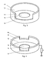
- Fig. 3
- eine Variante eines Einsatzteils und
- Fig. 4
- eine weitere Variante des Einsatzteils.
-
Fig. 1 zeigt das Prinzip einer Schlauchrollenpumpe. Hierbei ist ein Schlauch 30 in eine zylindrische Aufnahme eines Einsatzteils 10 eingesetzt und steht dabei umlaufend mit ungefähr 270° in Kontakt zu der Innenseite des Einsatzteils. Diese Fläche wird nachfolgend auch als Rollbett 12 bezeichnet. Koaxial zu dem Einsatzteil 10 ist ein Rotor 20 mit zwei Antriebsarmen angeordnet, an denen je ein Rollelement 24a, 24b in Form einer zylindrischen Walze drehbar gelagert ist. Der Rotor ist entsprechend der Antriebsrichtung 22 über einen Motor (nicht dargestellt) angetrieben. Dabei drückt das obere Rollelement 24b derart radial nach außen gegen den Schlauch 30, dass dieser sich lokal verschließt. Wenn nun der Antrieb den Rotor weiterbewegt, bewegt sich diese verschlossene Stelle im Uhrzeigersinn. Dabei kommt das untere Rollelement 24a in Eingriff mit dem Schlauch und verschließt diesen entsprechend und so wird das Fluidvolumen zwischen beiden verschlossenen Stellen in Längsrichtung des Schlauchs gefördert. Der Schlauch ist dabei ortsstabil zu dem Einsatzteil 10 und dessen Rollbett 12 und es findet eine Abrollbewegung zwischen den Rollelementen 24a, 24b und dem Schlauch statt. Der Außenrollradius 26 der Rollelemente ist dabei so bemessen, dass er im Wesentlichen um die doppelte Wandstärke des Schlauchs 30 kleiner als der Innenradius des Einsatzteils 10 ist, um so den Schlauch hinreichend gut zu verschließen, ohne ihn zu sehr zu quetschen. - Zur Realisierung einer gewünschten radialen Andruckkraft von den Rollelementen 24a, 24b gegen den Schlauch 30 kann, wie in
Fig. 2 dargestellt, auch jeweils eine Druckfeder 28 vorgesehen sein, welche sich am Rotor 20 abstützt und über einen Rollenarm 29 die Rollen 24a, 24b entsprechend nach außen drückt. Jeder der beiden Rollenarm 29 ist am Rotor 20 schwenkbar gelagert, weist eine Andruckfläche für die Druckfeder 28 und auch eine Lagerung für eines der Rollen 24a, 24b auf. Es kann auch eine höhere Anzahl an Rollelementen verwendet werden. - Das Einsatzteil 10 ist dabei als eine Art Dose aus einem metallischen Werkstoff, wie z.B. Edelstahlbleich, ausgeführt. Das heißt, es weist eine zylindrische Grundform auf und wird zur einen axialen Seite von einem Flansch 14 begrenzt, welcher sich radial nach innen erstreckt und eine koaxiale Öffnung 16 für die Antriebsachse des Rotors 20 frei lässt. Die zylindrische Stirnseite des Flanschs 14 ist in
Fig. 1 undFig. 3 mit dem Innendurchmesser des Flanschabschlusses 15 dargestellt. Durch eine Freimachung 18, welche an der zylindrischen Grundform des Einsatzteils 10 vom Flansch entfernt vorgesehen ist, wird gemäßFig. 1 der Schlauch in den Innenbereich des Einsatzteils 10 geleitet. Da die Freimachung gut 90° des Umfangs aufweist, beträgt die Rolllänge des Rollbetts knapp 270°. Für die Förderfunktion der Schlauchpumpe muss stets zumindest ein Rollelement den Schlauch verschließen und so würde bei zwei Rollelementen eine Rolllänge von 180° ausreichen. - Alternativ zu der Ausführung in
Fig. 3 kann der Flansch 14 auch radial nach außen zeigen oder es kann zusätzlich zu dem inFig. 3 dargestellten Flansch 14 ein weiterer nach außen gerichteter Flansch am anderen Ende des Einsatzteils vorgesehen sein. - Einleitend wurde der technische Effekt beschrieben, dass bei herkömmlichen Schlauchpumpen bei dem Abrollen der Rollen gegen den Schlauch, dem Abheben des Schlauchs von seinem Rollbett und v.a. auch beim Aufsetzen der jeweiligen Rolle auf den Schlauch im Einführungsbereich in die Schlauchpumpe triboelektrische Aufladungen und Störimpulse erzeugt werden. Diese werden insbesondere bei dem Kontakt von Kunststoffoberflächen zueinander erzeugt.
- Vorliegend ist das Einsatzteil 10 aus einem metallischen Werkstoff gefertigt und so weist das Rollbett, also die zylindrische Innenfläche des Einsatzteils, eine elektrisch leitende Oberfläche auf. Hierdurch wird der Effekt der Ladungstrennung und die entsprechende Aufladung stark reduziert oder vermieden, da durch den freien Ladungsaustausch an der leitenden Oberfläche die Bildung von einem lokalen Ladungsüberschuss oder Ladungsmangel verhindert wird. Ferner können auch die Rollelemente eine elektrisch leitende Oberfläche aufweisen und hierdurch werden auch an dem Schlauch-Rollelementkontakt entsprechende Aufladungen reduziert und/oder vermieden.
- Auch kann eine elektrisch leitende Verbindung von dem Rotor 20 mit dessen Rollen 24a, 24b zu dem Rollbett vorgesehen sein, wie etwa durch einen Schleifkontakt an der Antriebsachse des Rotors 20, der elektrisch leitend mit dem Einsatzteil 10 verbunden ist (nicht dargestellt) und so wird dieser Effekt der Vermeidung der Aufladungen noch verstärkt.
- In der hier beschriebenen Ausführungsform ist das gesamte Rollbett elektrisch leitend ausgeführt. Es tritt aber bereits eine deutliche Reduzierung der Störimpulse auf, wenn das Rollbett nur im Ein- und Ausführungsbereich des Schlauchs 30 mit leitenden und geerdeten Abschnitten versehen ist. Ladungen, welche sich auf dem Äußeren des Schlauchs befinden oder entsprechende Störimpulse können durch die Erdung abgeführt werden.
- Das Einsatzteil 10 kann in einem Tiefziehvorgang kostengünstig mit einer genauen Rundheit und mit einer glatten Oberfläche aus einem Metallblech hergestellt werden. Dieses Einsatzteil wird in ein Spritzgusswerkzeug eingesetzt. Im Spritzgusswerkzeug wird das Einsatzteil umspritzt und bildet eine formschlüssige und feste Verbindung mit dem umspritzten Körper der Schlauchpumpe. Auch kann die Schlauchpumpe in die Frontplatte des entsprechenden medizinischen Geräts integriert sein, um für den Bediener gut erreichbar zu sein. In diesem Fall wird das Einsatzteil in der entsprechenden Frontplatte umspritzt.
- Alternativ kann das Einsatzteil auch eine Metallfolie sein, welche ringförmig in das Spritzgusswerkzeug eingelegt und umspritzt werden kann.
- Alternativ kann die metallische Oberftäche des Rollbetts auch nachträglich auf ein gespritztes Kunststoffformteil aufgebracht werden. Für derartige leitende Beschichtungen kann die MID-Technologie (Molded Interconnection Device) verwendet werden. Diese Technologie wird zwar primär für die Erzeugung von dreidimensionalen Leiterbahnen für elektrische Schaltkreise verwendet, aber es ist auch möglich auf diese Weise durchgehende leitende Flächen zu erzeugen. Dabei wird ein entsprechend beschichtbarer Kunststoff verwendet, welcher galvanisch mit einer entsprechenden Metallschicht versehen wird. Wenn in einem Zweikomponentenspritzgussverfahren dieser beschichtbare Kunststoff ausschließlich im Bereich des Rollbetts verwendet wird, so kann für die Front des Geräts ein anderes Material zum Einsatz kommen. Auch kann eine Edelstahlfolie oder Edelstahlblech in die zylindrische Aufnahme eingeklemmt und/oder eingeklebt werden.
- Das Einsatzteil 10 (siehe
Fig. 3 ) weist eine Freimachung 18 auf, welche gemäßFig. 1 sowohl zur Ein- und Ausführung des Schlauches dient, so dass die Rolllänge, also die Andruckfläche des Schlauchs im Rollbett, 270° beträgt. Alternativ kann ein Einsatzteil gemäßFig. 4 verwendet werden, welches an gegenüberliegenden Stellen zwei kleinere Freimachungen 18 aufweist. Dieses Einsatzteil kann bei einer Schlauchpumpe verwendet werden, bei der der Schlauch auf einer ersten Seite in den zylindrischen Bereich eingeleitet wird, dort über anderthalb Umläufe geführt und auf einer zweiten gegenüberliegenden Seite die Pumpe verlässt. Auch kann der Schlauch mit mehr Umläufen in der Pumpe geführt werden. -
Fig. 4 zeigt schematisch einen Widerstand R, welcher elektrisch zwischen das Einsatzteil 10 und einem Potentialausgleich oder insbesondere einer Erdung geschaltet ist. Dieser Potentialausgleich kann auch mit dem Rotor 20 verbunden sein. Der Widerstand R bewirkt eine Begrenzung des Ableitstroms des Störsignals. Wenn ein empfindliches Gerät an dem Potentialausgleich oder der Erdung angeschlossen ist, so wird auf diese Weise verhindert, dass Störsignale über den Potentialausgleich an dieses Gerät weitergeleitet werden. - Bislang wurde im Ausführungsbeispiel eine Schlauchrollenpumpe beschrieben, welche Rollen als Roll- oder Andruckelemente verwendet. Die Erfindung ist entsprechend auf Schlauchpumpen mit kugelförmigen Rollelementen anwendbar. Eine derartige Schlauchpumpe ähnelt einem Radialkugellager, wobei dessen äußerer Laufring der Stator ist, welcher umlaufend eine konkave Vertiefung aufweist, in welcher der Schlauch liegt, der von vorzugsweise zwei nach außen drückenden Kugeln sukzessiv lokal verschlossen wird. Der Antrieb der Pumpe erfolgt direkt an den Kugeln, welche vergleichbar zu einem Radialkugellager in einem Käfig geführt sind.
Claims (11)
- Schlauchpumpe (1) zur Verwendung in der Medizintechnik mit einem Stator (40) und einem Rotor (20), wobei der Stator (40) ein Rollbett (12) aufweist, welches dem Kontaktbereich zu einem aufgenommenen Schlauch (30) entspricht und am Rotor (20) sind Rollelemente (24) vorgesehen, die geeignet sind, einen zwischen dem Rollbett (12) und den Rollelementen (24) aufgenommenen Schlauch zu verschließen wobei das Rollbett (12) zumindest teilweise eine elektrisch leitende Oberfläche zur Reduzierung und/oder Vermeidung von elektrostatischen Aufladungen des Schlauchs (30) aufweist, dadurch gekennzeichnet, dass
die elektrisch leitende Oberfläche (12) einen Potentialausgleich, insbesondere in Form einer Erdung, aufweist. - Schlauchpumpe gemäß Anspruch 1, dadurch gekennzeichnet, dass zwischen dem Potentialausgleich und der elektrisch leitenden Oberfläche (12) ein elektrischer Widerstand (R) vorgesehen ist.
- Schlauchpumpe gemäß Anspruch 1 oder 2, dadurch gekennzeichnet, dass die Rollelemente (24) eine elektrisch leitende Oberfläche aufweisen und dass von diesen Oberflächen ein elektrisch leitender Kontakt zu der elektrisch leitenden Oberfläche des Rollbetts (12) besteht.
- Schlauchpumpe gemäß einem der vorangegangenen Ansprüche, dadurch gekennzeichnet, dass das komplette Rollbett (12) eine durchgehend elektrisch leitende Oberfläche aufweist.
- Schlauchpumpe gemäß einem der vorangegangenen Ansprüche, dadurch gekennzeichnet, dass das Rollbett (12) eine zylindrisch nach innen gerichtete Oberfläche aufweist und die Rollelemente (24) als Rollen ausgeführt sind.
- Schlauchpumpe (1) gemäß einem der vorangegangenen Ansprüche, dadurch gekennzeichnet, dass die Kontur des Rollbetts an ein oder zwei Stellen Freimachungen (18) aufweist, um als Ein- oder Ausführung für den Schlauch aus der Schlauchpumpe zu dienen.
- Schlauchpumpe gemäß einem der vorangegangenen Ansprüche, dadurch gekennzeichnet, dass der Stator (40) aus einem elektrisch nicht leitenden Kunststoff in einem Spritzgussprozess hergestellt wurde und die elektrisch leitende Oberfläche die Oberfläche eines umspritzten metallischen Einsatzteils (10) oder einer umspritzten Metallfolie ist.
- Schlauchpumpe gemäß Anspruch 7, dadurch gekennzeichnet, dass das Einsatzteil (10) eine zylindrische Grundform mit einem Flansch (14) aufweist, welcher vorzugsweise komplett umlaufend und radial nach innen ausgerichtet ist.
- Schlauchpumpe gemäß einem der Ansprüche 1 bis 6, dadurch gekennzeichnet, dass die elektrisch leitende Oberfläche durch eine lokale leitende Beschichtung eines Spritzgussteils erzeugt wurde.
- Medizinisches Gerät zur extrakorporalen Blutbehandlung, insbesondere zur Dialyse und/oder eine Infusions- oder Transfusionsvorrichtung, mit einer Schlauchpumpe (1) nach einem der vorangegangenen Ansprüche.
- Medizinisches Gerät gemäß Anspruch 10, wobei das Gerät eine einem Benutzer zugewandte Bedien- und Funktionsfront aufweist, welche als ein Spritzgussteil geformt ist und wobei die Schlauchpumpe mit dem Rollbett einstückig in die Bedien- und Funktionsfront integriert ist.
Applications Claiming Priority (2)
| Application Number | Priority Date | Filing Date | Title |
|---|---|---|---|
| DE102009046406A DE102009046406B4 (de) | 2009-11-04 | 2009-11-04 | Schlauchpumpe |
| PCT/EP2010/066777 WO2011054890A1 (de) | 2009-11-04 | 2010-11-04 | Schlauchpumpe |
Publications (2)
| Publication Number | Publication Date |
|---|---|
| EP2496279A1 EP2496279A1 (de) | 2012-09-12 |
| EP2496279B1 true EP2496279B1 (de) | 2014-01-22 |
Family
ID=43501602
Family Applications (1)
| Application Number | Title | Priority Date | Filing Date |
|---|---|---|---|
| EP10771784.5A Active EP2496279B1 (de) | 2009-11-04 | 2010-11-04 | Schlauchpumpe |
Country Status (11)
| Country | Link |
|---|---|
| US (1) | US9243625B2 (de) |
| EP (1) | EP2496279B1 (de) |
| JP (1) | JP5518206B2 (de) |
| KR (1) | KR101771753B1 (de) |
| CN (1) | CN102596281B (de) |
| AU (1) | AU2010317054B2 (de) |
| CA (1) | CA2779865C (de) |
| DE (1) | DE102009046406B4 (de) |
| EA (1) | EA021639B1 (de) |
| IN (1) | IN2012DN04859A (de) |
| WO (1) | WO2011054890A1 (de) |
Families Citing this family (24)
| Publication number | Priority date | Publication date | Assignee | Title |
|---|---|---|---|---|
| US9746412B2 (en) | 2012-05-30 | 2017-08-29 | Iris International, Inc. | Flow cytometer |
| US10265025B2 (en) * | 2013-06-25 | 2019-04-23 | Biosense Webster (Israel) Ltd. | Electrocardiogram noise reduction |
| US9504522B2 (en) * | 2013-06-25 | 2016-11-29 | Biosense Webster (Israel) Ltd. | Electrocardiogram noise reduction |
| KR101443859B1 (ko) * | 2013-10-30 | 2014-09-24 | 김용배 | 호스식 약품 정량 이송펌프구조체 |
| KR101598053B1 (ko) * | 2014-03-13 | 2016-02-26 | 주식회사 베스테크 | 줄기세포 분리기의 연동펌프장치 |
| DE102015102658A1 (de) * | 2015-02-25 | 2016-08-25 | B. Braun Avitum Ag | Gehäusefrontintegrierte Blutpumpe |
| WO2017129193A1 (en) * | 2016-01-25 | 2017-08-03 | Fluisense Aps | Micro dosage peristaltic pump for micro dosage of fluid |
| DE102016005467A1 (de) * | 2016-05-06 | 2017-11-09 | Fresenius Medical Care Deutschland Gmbh | Medizinische Behandlungsvorrichtung und Schlauchset für eine medizinische Behandlungsvorrichtung sowie Verfahren zur Überwachung einer peristaltischen Schlauchpumpe |
| US10690127B2 (en) * | 2016-08-30 | 2020-06-23 | Alcon Inc. | Handheld ophthalmic probe with peristaltic pump and associated devices, systems, and methods |
| US20180117239A1 (en) * | 2016-11-02 | 2018-05-03 | St. Jude Medical, Cardiology Division, Inc. | Interface Tubing for Peristaltic Pump |
| KR101874808B1 (ko) | 2017-07-21 | 2018-08-06 | 엘븐트리 주식회사 | 무맥동 연동 펌프 |
| CN107829919B (zh) * | 2017-11-09 | 2024-01-30 | 四川君汇科技有限公司 | 滚珠式蠕动泵及泵管安装方法 |
| CN107725343B (zh) * | 2017-11-09 | 2024-01-30 | 四川君汇科技有限公司 | 组合式蠕动泵及组合定位安装方法 |
| DE102018116071A1 (de) * | 2018-07-03 | 2020-01-09 | B. Braun Avitum Ag | Verfahren zum automatisierten Primen eines extrakorporalen Blutleitungssystems sowie eine Vorrichtung hierfür |
| EP3963241B1 (de) * | 2019-04-30 | 2025-08-27 | Saint-Gobain Performance Plastics Corporation | Dissipative peristaltische pumpenschläuche |
| CN110307362B (zh) * | 2019-07-01 | 2020-11-03 | 陕西理工大学 | 一种流路调节切换装置及方法 |
| US11549503B2 (en) * | 2019-08-28 | 2023-01-10 | Reelreactor, Llc | Fluid isolating peristaltic pump |
| JP7405585B2 (ja) * | 2019-12-04 | 2023-12-26 | テルモ株式会社 | 医療用ポンプモジュール及び医療用ポンプ |
| EP3991764B1 (de) | 2020-10-27 | 2024-03-06 | Bellco S.r.l. | Durchflussmesser zum dosieren von wasser in einem dialysesystem |
| ES3007240T3 (en) | 2020-10-30 | 2025-03-19 | Bellco Srl | Dialysis cassette with pump features |
| US12318528B2 (en) | 2020-10-30 | 2025-06-03 | Mozarc Medical Us Llc | Variable orifice fistula graft |
| EP4008376A1 (de) | 2020-12-03 | 2022-06-08 | Medtronic, Inc. | Flexibles rohr-routing-zubehör für peritoneal dialysis system |
| JP7826873B2 (ja) * | 2022-07-29 | 2026-03-10 | ニプロ株式会社 | 医療用輸液装置 |
| DE102023131538A1 (de) * | 2023-11-13 | 2025-05-15 | Ulrich Gmbh & Co. Kg | Injektionssystem |
Family Cites Families (22)
| Publication number | Priority date | Publication date | Assignee | Title |
|---|---|---|---|---|
| DE36633C (de) | G. MAHLOW in Stettin | Spiegelreflektorhalter an Klavieren | ||
| US3580893A (en) | 1966-10-25 | 1971-05-25 | Gulf Research Development Co | Process for the preparation of cyclic acid anhydrides |
| US3580983A (en) * | 1969-12-03 | 1971-05-25 | Nat Catheter Corp | Conductive line tube |
| US4277226A (en) * | 1979-03-09 | 1981-07-07 | Avi, Inc. | IV Pump with empty supply reservoir and occlusion detector |
| JPS56113083A (en) * | 1980-02-12 | 1981-09-05 | Terumo Corp | Choke detection method and device for peristaltic liquid pump |
| JPH0311254Y2 (de) * | 1987-10-23 | 1991-03-19 | ||
| JP2529404B2 (ja) | 1989-08-02 | 1996-08-28 | 松下電器産業株式会社 | マスキング係数決定装置 |
| JP2510135Y2 (ja) * | 1989-10-31 | 1996-09-11 | 株式会社島津製作所 | ペリスタポンプ |
| US5127907A (en) * | 1990-12-06 | 1992-07-07 | Abbott Laboratories | System for eliminating or reducing static electricity in infusion pumping systems |
| US5324180A (en) * | 1992-09-04 | 1994-06-28 | Allergan, Inc. | Surgical instrument with drawer loading cassette system |
| US6533747B1 (en) * | 2000-05-23 | 2003-03-18 | Chf Solutions, Inc. | Extracorporeal circuit for peripheral vein fluid removal |
| MXPA04000801A (es) * | 2003-01-29 | 2005-06-17 | Innovamedica S A De C V | Anastomosis auricular-arterial de bajo flujo para revascularizacion del miocardio auxiliada por bomba sin derivacion cardiopulmonar. |
| US7074021B2 (en) * | 2003-05-12 | 2006-07-11 | Byrne Medical, Inc. | Cartridge to be used with a peristaltic pump |
| ITMO20030165A1 (it) * | 2003-06-04 | 2004-12-05 | Gambro Lundia Ab | Giunto per linee di trasporto fluido ad uso medicale. |
| JP4317187B2 (ja) | 2003-06-05 | 2009-08-19 | フルオー・テクノロジーズ・コーポレイシヨン | 液化天然ガスの再ガス化の構成および方法 |
| US7001153B2 (en) * | 2003-06-30 | 2006-02-21 | Blue-White Industries | Peristaltic injector pump leak monitor |
| US7223079B2 (en) * | 2003-07-28 | 2007-05-29 | The Coca-Cola Company | Quick loading peristaltic pump |
| DK1763636T3 (da) * | 2004-05-14 | 2008-12-01 | Fresenius Medical Care De Gmbh | Rulle pumpe |
| EP1942964B1 (de) * | 2005-09-23 | 2015-08-26 | Medtronic Inc. | Schlauchhaltevorrichtung für rollpumpen |
| DE102006042646B4 (de) * | 2006-09-12 | 2008-11-20 | Fresenius Medical Care Deutschland Gmbh | Vorrichtung und Verfahren zur Überwachung eines Zugangs zu einem Patienten, insbesondere eines Gefäßzugangs bei einer extrakorporalen Blutbehandlung |
| WO2009044220A1 (en) * | 2007-10-03 | 2009-04-09 | Gambro Lundia Ab | Medical apparatus |
| JP5094507B2 (ja) * | 2008-03-28 | 2012-12-12 | 富士フイルム株式会社 | チューブポンプ、インクジェット記録装置、インクジェット記録方法及び印刷物 |
-
2009
- 2009-11-04 DE DE102009046406A patent/DE102009046406B4/de not_active Expired - Fee Related
-
2010
- 2010-11-04 AU AU2010317054A patent/AU2010317054B2/en not_active Ceased
- 2010-11-04 US US13/505,616 patent/US9243625B2/en active Active
- 2010-11-04 KR KR1020127014396A patent/KR101771753B1/ko not_active Expired - Fee Related
- 2010-11-04 IN IN4859DEN2012 patent/IN2012DN04859A/en unknown
- 2010-11-04 WO PCT/EP2010/066777 patent/WO2011054890A1/de not_active Ceased
- 2010-11-04 JP JP2012535878A patent/JP5518206B2/ja not_active Expired - Fee Related
- 2010-11-04 EA EA201290282A patent/EA021639B1/ru not_active IP Right Cessation
- 2010-11-04 CN CN201080049896.2A patent/CN102596281B/zh not_active Expired - Fee Related
- 2010-11-04 EP EP10771784.5A patent/EP2496279B1/de active Active
- 2010-11-04 CA CA2779865A patent/CA2779865C/en not_active Expired - Fee Related
Also Published As
| Publication number | Publication date |
|---|---|
| EA021639B1 (ru) | 2015-07-30 |
| KR101771753B1 (ko) | 2017-08-25 |
| DE102009046406A1 (de) | 2011-05-05 |
| IN2012DN04859A (de) | 2015-09-25 |
| WO2011054890A1 (de) | 2011-05-12 |
| AU2010317054B2 (en) | 2015-02-05 |
| EA201290282A1 (ru) | 2012-11-30 |
| AU2010317054A1 (en) | 2012-06-21 |
| DE102009046406B4 (de) | 2012-04-26 |
| CN102596281A (zh) | 2012-07-18 |
| EP2496279A1 (de) | 2012-09-12 |
| CA2779865C (en) | 2018-02-27 |
| KR20120081621A (ko) | 2012-07-19 |
| US20120282126A1 (en) | 2012-11-08 |
| US9243625B2 (en) | 2016-01-26 |
| CN102596281B (zh) | 2015-05-13 |
| JP5518206B2 (ja) | 2014-06-11 |
| JP2013509899A (ja) | 2013-03-21 |
| CA2779865A1 (en) | 2011-05-12 |
Similar Documents
| Publication | Publication Date | Title |
|---|---|---|
| EP2496279B1 (de) | Schlauchpumpe | |
| EP3061474B1 (de) | Gehäusefrontintegrierte blutpumpe | |
| EP0904630A1 (de) | Verfahren zur herstellung eines mikromotors | |
| DE102009049783A1 (de) | Elektrisch leitfähige Pipettenspitze | |
| WO2016207066A1 (de) | Vorrichtung und verfahren zur druckmessung am herzen eines patienten | |
| DE102014009103B4 (de) | Drehmomentsensor-abdeckung | |
| EP2990647B1 (de) | Schlauchpumpe | |
| DE69624054T2 (de) | Einrichtung für Beschichtung von Gegenständen unter Verwendung einer porösen elastischen Matrix | |
| DE102008019165A1 (de) | Kabelverschraubung, insbesondere für ein Abschirm- oder Erdungskabel | |
| EP3281653B1 (de) | Peristaltikpumpe mit modularem gehäuse | |
| DE19962498A1 (de) | Pumpenkörper für eine medizinische Zahnradpumpe | |
| DE69624393T2 (de) | Antrieb für Pumpelemente, insbesondere für Herzunterstützungsvorrichtungen | |
| DE3338002A1 (de) | Dosiervorrichtung fuer eine fluessigkeit | |
| WO2025104070A1 (de) | Injektionssystem | |
| DE202013104131U1 (de) | Elektrisches Federelement und Kontaktelement mit einem Federelement | |
| DE202009001948U1 (de) | Elektrisch leitfähige Rolle | |
| WO2025149277A1 (de) | Schmiermittelpumpe | |
| DE102022209907A1 (de) | Am Körper tragbare Vorrichtung zur Erkennung einer Stenose und System damit | |
| DE202009000100U1 (de) | Elektrisch leitfähige Rolle | |
| EP1956345B1 (de) | Modul zur kapazitiven Abtastung und Verbrauchszähler | |
| WO2021053077A1 (de) | Elektromotorisch angetriebenes aggregat für ein fahrzeug | |
| DE102023121996A1 (de) | Bypass-Vorrichtung, Wälzlager mit einer Bypass-Vorrichtung sowie Verfahren zur Ableitung elektrostatischer Ladungen an einem Wälzlager | |
| EP2363092A1 (de) | Medizinische, insbesondere dentale, Behandlungsvorrichtung mit einem Dichtelement | |
| DE202015102189U1 (de) | Injektor zur Injektion von Kontrastmitteln |
Legal Events
| Date | Code | Title | Description |
|---|---|---|---|
| PUAI | Public reference made under article 153(3) epc to a published international application that has entered the european phase |
Free format text: ORIGINAL CODE: 0009012 |
|
| 17P | Request for examination filed |
Effective date: 20120604 |
|
| AK | Designated contracting states |
Kind code of ref document: A1 Designated state(s): AL AT BE BG CH CY CZ DE DK EE ES FI FR GB GR HR HU IE IS IT LI LT LU LV MC MK MT NL NO PL PT RO RS SE SI SK SM TR |
|
| DAX | Request for extension of the european patent (deleted) | ||
| GRAP | Despatch of communication of intention to grant a patent |
Free format text: ORIGINAL CODE: EPIDOSNIGR1 |
|
| INTG | Intention to grant announced |
Effective date: 20130813 |
|
| GRAS | Grant fee paid |
Free format text: ORIGINAL CODE: EPIDOSNIGR3 |
|
| GRAA | (expected) grant |
Free format text: ORIGINAL CODE: 0009210 |
|
| AK | Designated contracting states |
Kind code of ref document: B1 Designated state(s): AL AT BE BG CH CY CZ DE DK EE ES FI FR GB GR HR HU IE IS IT LI LT LU LV MC MK MT NL NO PL PT RO RS SE SI SK SM TR |
|
| REG | Reference to a national code |
Ref country code: GB Ref legal event code: FG4D Free format text: NOT ENGLISH |
|
| REG | Reference to a national code |
Ref country code: CH Ref legal event code: EP |
|
| REG | Reference to a national code |
Ref country code: AT Ref legal event code: REF Ref document number: 650463 Country of ref document: AT Kind code of ref document: T Effective date: 20140215 |
|
| REG | Reference to a national code |
Ref country code: IE Ref legal event code: FG4D Free format text: LANGUAGE OF EP DOCUMENT: GERMAN |
|
| REG | Reference to a national code |
Ref country code: DE Ref legal event code: R096 Ref document number: 502010006029 Country of ref document: DE Effective date: 20140306 |
|
| REG | Reference to a national code |
Ref country code: SE Ref legal event code: TRGR |
|
| REG | Reference to a national code |
Ref country code: NL Ref legal event code: VDEP Effective date: 20140122 |
|
| REG | Reference to a national code |
Ref country code: LT Ref legal event code: MG4D |
|
| PG25 | Lapsed in a contracting state [announced via postgrant information from national office to epo] |
Ref country code: NO Free format text: LAPSE BECAUSE OF FAILURE TO SUBMIT A TRANSLATION OF THE DESCRIPTION OR TO PAY THE FEE WITHIN THE PRESCRIBED TIME-LIMIT Effective date: 20140422 Ref country code: LT Free format text: LAPSE BECAUSE OF FAILURE TO SUBMIT A TRANSLATION OF THE DESCRIPTION OR TO PAY THE FEE WITHIN THE PRESCRIBED TIME-LIMIT Effective date: 20140122 Ref country code: IS Free format text: LAPSE BECAUSE OF FAILURE TO SUBMIT A TRANSLATION OF THE DESCRIPTION OR TO PAY THE FEE WITHIN THE PRESCRIBED TIME-LIMIT Effective date: 20140522 |
|
| PG25 | Lapsed in a contracting state [announced via postgrant information from national office to epo] |
Ref country code: NL Free format text: LAPSE BECAUSE OF FAILURE TO SUBMIT A TRANSLATION OF THE DESCRIPTION OR TO PAY THE FEE WITHIN THE PRESCRIBED TIME-LIMIT Effective date: 20140122 Ref country code: PT Free format text: LAPSE BECAUSE OF FAILURE TO SUBMIT A TRANSLATION OF THE DESCRIPTION OR TO PAY THE FEE WITHIN THE PRESCRIBED TIME-LIMIT Effective date: 20140522 Ref country code: FI Free format text: LAPSE BECAUSE OF FAILURE TO SUBMIT A TRANSLATION OF THE DESCRIPTION OR TO PAY THE FEE WITHIN THE PRESCRIBED TIME-LIMIT Effective date: 20140122 Ref country code: ES Free format text: LAPSE BECAUSE OF FAILURE TO SUBMIT A TRANSLATION OF THE DESCRIPTION OR TO PAY THE FEE WITHIN THE PRESCRIBED TIME-LIMIT Effective date: 20140122 Ref country code: CY Free format text: LAPSE BECAUSE OF FAILURE TO SUBMIT A TRANSLATION OF THE DESCRIPTION OR TO PAY THE FEE WITHIN THE PRESCRIBED TIME-LIMIT Effective date: 20140122 |
|
| PG25 | Lapsed in a contracting state [announced via postgrant information from national office to epo] |
Ref country code: RS Free format text: LAPSE BECAUSE OF FAILURE TO SUBMIT A TRANSLATION OF THE DESCRIPTION OR TO PAY THE FEE WITHIN THE PRESCRIBED TIME-LIMIT Effective date: 20140122 Ref country code: HR Free format text: LAPSE BECAUSE OF FAILURE TO SUBMIT A TRANSLATION OF THE DESCRIPTION OR TO PAY THE FEE WITHIN THE PRESCRIBED TIME-LIMIT Effective date: 20140122 Ref country code: LV Free format text: LAPSE BECAUSE OF FAILURE TO SUBMIT A TRANSLATION OF THE DESCRIPTION OR TO PAY THE FEE WITHIN THE PRESCRIBED TIME-LIMIT Effective date: 20140122 |
|
| REG | Reference to a national code |
Ref country code: DE Ref legal event code: R097 Ref document number: 502010006029 Country of ref document: DE |
|
| PG25 | Lapsed in a contracting state [announced via postgrant information from national office to epo] |
Ref country code: RO Free format text: LAPSE BECAUSE OF FAILURE TO SUBMIT A TRANSLATION OF THE DESCRIPTION OR TO PAY THE FEE WITHIN THE PRESCRIBED TIME-LIMIT Effective date: 20140122 Ref country code: EE Free format text: LAPSE BECAUSE OF FAILURE TO SUBMIT A TRANSLATION OF THE DESCRIPTION OR TO PAY THE FEE WITHIN THE PRESCRIBED TIME-LIMIT Effective date: 20140122 Ref country code: CZ Free format text: LAPSE BECAUSE OF FAILURE TO SUBMIT A TRANSLATION OF THE DESCRIPTION OR TO PAY THE FEE WITHIN THE PRESCRIBED TIME-LIMIT Effective date: 20140122 Ref country code: DK Free format text: LAPSE BECAUSE OF FAILURE TO SUBMIT A TRANSLATION OF THE DESCRIPTION OR TO PAY THE FEE WITHIN THE PRESCRIBED TIME-LIMIT Effective date: 20140122 |
|
| PG25 | Lapsed in a contracting state [announced via postgrant information from national office to epo] |
Ref country code: SK Free format text: LAPSE BECAUSE OF FAILURE TO SUBMIT A TRANSLATION OF THE DESCRIPTION OR TO PAY THE FEE WITHIN THE PRESCRIBED TIME-LIMIT Effective date: 20140122 Ref country code: PL Free format text: LAPSE BECAUSE OF FAILURE TO SUBMIT A TRANSLATION OF THE DESCRIPTION OR TO PAY THE FEE WITHIN THE PRESCRIBED TIME-LIMIT Effective date: 20140122 |
|
| PLBE | No opposition filed within time limit |
Free format text: ORIGINAL CODE: 0009261 |
|
| STAA | Information on the status of an ep patent application or granted ep patent |
Free format text: STATUS: NO OPPOSITION FILED WITHIN TIME LIMIT |
|
| 26N | No opposition filed |
Effective date: 20141023 |
|
| REG | Reference to a national code |
Ref country code: DE Ref legal event code: R097 Ref document number: 502010006029 Country of ref document: DE Effective date: 20141023 |
|
| PG25 | Lapsed in a contracting state [announced via postgrant information from national office to epo] |
Ref country code: SI Free format text: LAPSE BECAUSE OF FAILURE TO SUBMIT A TRANSLATION OF THE DESCRIPTION OR TO PAY THE FEE WITHIN THE PRESCRIBED TIME-LIMIT Effective date: 20140122 |
|
| PG25 | Lapsed in a contracting state [announced via postgrant information from national office to epo] |
Ref country code: BE Free format text: LAPSE BECAUSE OF NON-PAYMENT OF DUE FEES Effective date: 20141130 Ref country code: MC Free format text: LAPSE BECAUSE OF FAILURE TO SUBMIT A TRANSLATION OF THE DESCRIPTION OR TO PAY THE FEE WITHIN THE PRESCRIBED TIME-LIMIT Effective date: 20140122 Ref country code: LU Free format text: LAPSE BECAUSE OF FAILURE TO SUBMIT A TRANSLATION OF THE DESCRIPTION OR TO PAY THE FEE WITHIN THE PRESCRIBED TIME-LIMIT Effective date: 20141104 |
|
| REG | Reference to a national code |
Ref country code: CH Ref legal event code: PL |
|
| PG25 | Lapsed in a contracting state [announced via postgrant information from national office to epo] |
Ref country code: LI Free format text: LAPSE BECAUSE OF NON-PAYMENT OF DUE FEES Effective date: 20141130 Ref country code: CH Free format text: LAPSE BECAUSE OF NON-PAYMENT OF DUE FEES Effective date: 20141130 |
|
| REG | Reference to a national code |
Ref country code: IE Ref legal event code: MM4A |
|
| REG | Reference to a national code |
Ref country code: FR Ref legal event code: PLFP Year of fee payment: 6 |
|
| PG25 | Lapsed in a contracting state [announced via postgrant information from national office to epo] |
Ref country code: IE Free format text: LAPSE BECAUSE OF NON-PAYMENT OF DUE FEES Effective date: 20141104 |
|
| PG25 | Lapsed in a contracting state [announced via postgrant information from national office to epo] |
Ref country code: SM Free format text: LAPSE BECAUSE OF FAILURE TO SUBMIT A TRANSLATION OF THE DESCRIPTION OR TO PAY THE FEE WITHIN THE PRESCRIBED TIME-LIMIT Effective date: 20140122 |
|
| PG25 | Lapsed in a contracting state [announced via postgrant information from national office to epo] |
Ref country code: GR Free format text: LAPSE BECAUSE OF FAILURE TO SUBMIT A TRANSLATION OF THE DESCRIPTION OR TO PAY THE FEE WITHIN THE PRESCRIBED TIME-LIMIT Effective date: 20140423 Ref country code: BG Free format text: LAPSE BECAUSE OF FAILURE TO SUBMIT A TRANSLATION OF THE DESCRIPTION OR TO PAY THE FEE WITHIN THE PRESCRIBED TIME-LIMIT Effective date: 20140122 |
|
| PG25 | Lapsed in a contracting state [announced via postgrant information from national office to epo] |
Ref country code: MT Free format text: LAPSE BECAUSE OF FAILURE TO SUBMIT A TRANSLATION OF THE DESCRIPTION OR TO PAY THE FEE WITHIN THE PRESCRIBED TIME-LIMIT Effective date: 20140122 Ref country code: HU Free format text: LAPSE BECAUSE OF FAILURE TO SUBMIT A TRANSLATION OF THE DESCRIPTION OR TO PAY THE FEE WITHIN THE PRESCRIBED TIME-LIMIT; INVALID AB INITIO Effective date: 20101104 Ref country code: TR Free format text: LAPSE BECAUSE OF FAILURE TO SUBMIT A TRANSLATION OF THE DESCRIPTION OR TO PAY THE FEE WITHIN THE PRESCRIBED TIME-LIMIT Effective date: 20140122 |
|
| REG | Reference to a national code |
Ref country code: FR Ref legal event code: PLFP Year of fee payment: 7 |
|
| REG | Reference to a national code |
Ref country code: AT Ref legal event code: MM01 Ref document number: 650463 Country of ref document: AT Kind code of ref document: T Effective date: 20151104 |
|
| PG25 | Lapsed in a contracting state [announced via postgrant information from national office to epo] |
Ref country code: AT Free format text: LAPSE BECAUSE OF NON-PAYMENT OF DUE FEES Effective date: 20151104 |
|
| REG | Reference to a national code |
Ref country code: FR Ref legal event code: PLFP Year of fee payment: 8 |
|
| PG25 | Lapsed in a contracting state [announced via postgrant information from national office to epo] |
Ref country code: MK Free format text: LAPSE BECAUSE OF FAILURE TO SUBMIT A TRANSLATION OF THE DESCRIPTION OR TO PAY THE FEE WITHIN THE PRESCRIBED TIME-LIMIT Effective date: 20140122 |
|
| REG | Reference to a national code |
Ref country code: FR Ref legal event code: PLFP Year of fee payment: 9 |
|
| PG25 | Lapsed in a contracting state [announced via postgrant information from national office to epo] |
Ref country code: AL Free format text: LAPSE BECAUSE OF FAILURE TO SUBMIT A TRANSLATION OF THE DESCRIPTION OR TO PAY THE FEE WITHIN THE PRESCRIBED TIME-LIMIT Effective date: 20140122 |
|
| REG | Reference to a national code |
Ref country code: DE Ref legal event code: R079 Ref document number: 502010006029 Country of ref document: DE Free format text: PREVIOUS MAIN CLASS: A61M0001100000 Ipc: A61M0060000000 |
|
| PGFP | Annual fee paid to national office [announced via postgrant information from national office to epo] |
Ref country code: SE Payment date: 20201026 Year of fee payment: 11 Ref country code: IT Payment date: 20201021 Year of fee payment: 11 Ref country code: GB Payment date: 20201021 Year of fee payment: 11 Ref country code: FR Payment date: 20201021 Year of fee payment: 11 |
|
| GBPC | Gb: european patent ceased through non-payment of renewal fee |
Effective date: 20211104 |
|
| PG25 | Lapsed in a contracting state [announced via postgrant information from national office to epo] |
Ref country code: SE Free format text: LAPSE BECAUSE OF NON-PAYMENT OF DUE FEES Effective date: 20211105 |
|
| PG25 | Lapsed in a contracting state [announced via postgrant information from national office to epo] |
Ref country code: GB Free format text: LAPSE BECAUSE OF NON-PAYMENT OF DUE FEES Effective date: 20211104 |
|
| PG25 | Lapsed in a contracting state [announced via postgrant information from national office to epo] |
Ref country code: FR Free format text: LAPSE BECAUSE OF NON-PAYMENT OF DUE FEES Effective date: 20211130 |
|
| PG25 | Lapsed in a contracting state [announced via postgrant information from national office to epo] |
Ref country code: IT Free format text: LAPSE BECAUSE OF NON-PAYMENT OF DUE FEES Effective date: 20211104 |
|
| P01 | Opt-out of the competence of the unified patent court (upc) registered |
Effective date: 20230602 |
|
| REG | Reference to a national code |
Ref country code: DE Ref legal event code: R082 Ref document number: 502010006029 Country of ref document: DE Representative=s name: MAUCHER JENKINS PATENTANWAELTE & RECHTSANWAELT, DE |
|
| PGFP | Annual fee paid to national office [announced via postgrant information from national office to epo] |
Ref country code: DE Payment date: 20251022 Year of fee payment: 16 |