EP2495500A2 - Système de fourniture d'eau chaude - Google Patents
Système de fourniture d'eau chaude Download PDFInfo
- Publication number
- EP2495500A2 EP2495500A2 EP12001244A EP12001244A EP2495500A2 EP 2495500 A2 EP2495500 A2 EP 2495500A2 EP 12001244 A EP12001244 A EP 12001244A EP 12001244 A EP12001244 A EP 12001244A EP 2495500 A2 EP2495500 A2 EP 2495500A2
- Authority
- EP
- European Patent Office
- Prior art keywords
- hot water
- pipe
- tank
- heat insulation
- water supply
- Prior art date
- Legal status (The legal status is an assumption and is not a legal conclusion. Google has not performed a legal analysis and makes no representation as to the accuracy of the status listed.)
- Granted
Links
Images


Classifications
-
- F—MECHANICAL ENGINEERING; LIGHTING; HEATING; WEAPONS; BLASTING
- F24—HEATING; RANGES; VENTILATING
- F24D—DOMESTIC- OR SPACE-HEATING SYSTEMS, e.g. CENTRAL HEATING SYSTEMS; DOMESTIC HOT-WATER SUPPLY SYSTEMS; ELEMENTS OR COMPONENTS THEREFOR
- F24D17/00—Domestic hot-water supply systems
- F24D17/02—Domestic hot-water supply systems using heat pumps
-
- F—MECHANICAL ENGINEERING; LIGHTING; HEATING; WEAPONS; BLASTING
- F24—HEATING; RANGES; VENTILATING
- F24D—DOMESTIC- OR SPACE-HEATING SYSTEMS, e.g. CENTRAL HEATING SYSTEMS; DOMESTIC HOT-WATER SUPPLY SYSTEMS; ELEMENTS OR COMPONENTS THEREFOR
- F24D3/00—Hot-water central heating systems
- F24D3/18—Hot-water central heating systems using heat pumps
-
- F—MECHANICAL ENGINEERING; LIGHTING; HEATING; WEAPONS; BLASTING
- F24—HEATING; RANGES; VENTILATING
- F24H—FLUID HEATERS, e.g. WATER OR AIR HEATERS, HAVING HEAT-GENERATING MEANS, e.g. HEAT PUMPS, IN GENERAL
- F24H1/00—Water heaters, e.g. boilers, continuous-flow heaters or water-storage heaters
- F24H1/18—Water-storage heaters
- F24H1/181—Construction of the tank
- F24H1/182—Insulation
-
- F—MECHANICAL ENGINEERING; LIGHTING; HEATING; WEAPONS; BLASTING
- F24—HEATING; RANGES; VENTILATING
- F24H—FLUID HEATERS, e.g. WATER OR AIR HEATERS, HAVING HEAT-GENERATING MEANS, e.g. HEAT PUMPS, IN GENERAL
- F24H1/00—Water heaters, e.g. boilers, continuous-flow heaters or water-storage heaters
- F24H1/18—Water-storage heaters
- F24H1/20—Water-storage heaters with immersed heating elements, e.g. electric elements or furnace tubes
- F24H1/208—Water-storage heaters with immersed heating elements, e.g. electric elements or furnace tubes with tubes filled with heat transfer fluid
-
- F—MECHANICAL ENGINEERING; LIGHTING; HEATING; WEAPONS; BLASTING
- F24—HEATING; RANGES; VENTILATING
- F24H—FLUID HEATERS, e.g. WATER OR AIR HEATERS, HAVING HEAT-GENERATING MEANS, e.g. HEAT PUMPS, IN GENERAL
- F24H4/00—Fluid heaters characterised by the use of heat pumps
- F24H4/02—Water heaters
- F24H4/04—Storage heaters
-
- Y—GENERAL TAGGING OF NEW TECHNOLOGICAL DEVELOPMENTS; GENERAL TAGGING OF CROSS-SECTIONAL TECHNOLOGIES SPANNING OVER SEVERAL SECTIONS OF THE IPC; TECHNICAL SUBJECTS COVERED BY FORMER USPC CROSS-REFERENCE ART COLLECTIONS [XRACs] AND DIGESTS
- Y02—TECHNOLOGIES OR APPLICATIONS FOR MITIGATION OR ADAPTATION AGAINST CLIMATE CHANGE
- Y02B—CLIMATE CHANGE MITIGATION TECHNOLOGIES RELATED TO BUILDINGS, e.g. HOUSING, HOUSE APPLIANCES OR RELATED END-USER APPLICATIONS
- Y02B30/00—Energy efficient heating, ventilation or air conditioning [HVAC]
- Y02B30/12—Hot water central heating systems using heat pumps
Definitions
- the present invention relates to a hot water supply system.
- Patent Literature 1 there is a hot water supply tank to which a vacuum heat insulation member is applied (refer to Patent Literature 1, for example).
- a vacuum heat insulation member is applied to an outer periphery of the hot water supply tank, a heat leakage amount of the hot water supply tank is reduced. As a result, power consumption is reduced.
- An object of the present invention is to reduce the size of a hot water supply system as a whole product by reducing an amount of a heat insulation member to be used for heat-insulating pipes in the hot water supply system, for example.
- a hot water supply system may include:
- the tank and the heat insulation member there is formed, between the tank and the heat insulation member, a space where the connection portion and at least a part of the extension portion of at least one pipe are disposed. Accordingly, an amount of the heat insulation member to be used for heat insulation of the pipes is reduced. The size of the hot water supply system as a whole product is thereby reduced.
- Fig. 1 is a diagram showing a configuration of a hot water supply and heating system 10 according to the first embodiment.
- the hot water supply and heating system 10 includes a tank 11, a heat pump heat source unit 13, a water circulation pump 15, an electromagnetic three-way valve 16, and a hot water heating appliance 17 (e.g., floor heating).
- the hot water supply and heating system 10 further includes a water supply pipe 20, a hot water discharge pipe 21, a return pipe 22, and an inlet pipe 23, as an example of a plurality of pipes.
- a water circuit 10a, a hot water supply circuit 10b, and a heating circuit 10c are configured to form an example of a fluid circuit.
- Water which is an example of a fluid, circulates in the water circuit 10a, the hot water supply circuit 10b, and the heating circuit 10c.
- the heat pump heat source unit 13 includes a heat pump circuit in which an expansion device, an evaporator, a compressor, and a water refrigerant heat exchanger 14 (e.g., a condenser) are connected and a refrigerant (e.g., CO 2 ) circulates.
- the compressor compresses and heats the refrigerant.
- the water refrigerant heat exchanger 14 heats the water flowing in the water circuit 10a, using the refrigerant heated by the compressor.
- the expansion device cools the refrigerant by expansion cooling.
- the evaporator recovers heat for the refrigerant from outside air after the refrigerant has been cooled by the expansion device. In this manner, the heat pump heat source unit 13 performs a heat pump cycle operation, thereby heating the water circulating in the water circuit 10a.
- the electromagnetic three-way valve 16 connects respective water supply paths for the water circuit 10a, the hot water supply circuit 10b, and the heating circuit 10c.
- the electromagnetic three-way valve 16 causes the water heated by a heat pump cycle of the heat pump heat source unit 13 to flow into the hot water supply circuit 10b and the heating circuit 10c. Respective amounts of the water to be flown into the hot water supply circuit 10b and the heating circuit 10c are controlled from an outside.
- the tank 11 includes a hot water storage tank 11a and a heat exchanger 12 (which is specifically a water heat exchanger).
- the hot water storage tank 11a stores water.
- the heat exchanger 12 heats the water stored in the hot water storage tank 11a, using the water circulating in the hot water supply circuit 10b (i.e., the water heated by the heat pump cycle of the heat pump heat source unit 13).
- the water supply pipe 20 supplies water to the hot water storage tank 11a of the tank 11.
- the inlet pipe 23 causes the water circulating in the hot water supply circuit 10b to flow into the heat exchanger 12 of the tank 11.
- the return pipe 22 returns the water used by the heat exchanger 12 to the hot water supply circuit 10b.
- the hot water discharge pipe 21 causes the water heated by the heat exchanger 12 to flow out from the hot water storage tank 11 a.
- the hot water supply and heating system 10 in this embodiment is an example of a hot water supply system and does not need to include the hot water heating appliance 17. In such a case, the electromagnetic three-way valve 16 is not necessary.
- the tank 11 in this embodiment stores the water heated by indirectly using the heat pump cycle
- the tank 11 may store water heated by directly using the heat pump cycle.
- the tank 11 does not need to include the heat exchanger 12.
- the water circulating in the hot water supply circuit 10b flows into the hot water storage tank 11a of the tank 11 through the inlet pipe 23, and is then stored in the hot water storage tank 11a. After this water has been used, the water is returned to the hot water supply circuit 10b through the return pipe 22.
- the water separately supplied from the water supply pipe 20 is returned to the hot water supply circuit 10b through the return pipe 22.
- water in the water circuit 10a is heated by the water refrigerant heat exchanger 14 provided within the heat pump heat source unit 13. Hot water obtained by the heating is circulated in the water circuit 10a by the water circulation pump 15. Supply of the hot water discharged from the water circulation pump 15 is switched to the hot water supply circuit 10b and the heating circuit 10c by the electromagnetic three-way valve 16. The hot water in the hot water supply circuit 10b is sent to the heat exchanger 12 provided in the hot water storage tank 11 la of the tank 11 through the inlet pipe 23. The hot water sent to the heat exchanger 12 is heat-exchanged by water in the hot water storage tank 11 a, and is then returned to the water circuit 10a again by the water circulation pump 15 through the return pipe 22.
- Hot water in the hot water storage tank 11a heated by the heat exchange is used for a shower or the like through the hot water discharge pipe 21.
- the hot water in the heating circuit 10c is sent to the hot water heating appliance 17. Then, heat of the hot water is radiated by heating an indoor space, and the hot water is then returned to the water circuit 10a again by the water circulation pump 15.
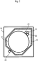
- Fig. 2 is a cross sectional view showing heat insulation of the tank 11 and the pipes of the hot water supply and heating system 10.
- Fig. 3 is a longitudinal sectional view showing heat insulation of the tank 11 and the pipes of the hot water supply and heating system 10.
- the hot water supply and heating system 10 further includes a case 18 enclosing the tank 11 (i.e., the outer case of the hot water supply tank) and a heat insulation member 19 (which is specifically a vacuum heat insulation member).
- the case 18 has a rectangular parallelepiped shape, for example, and holds the tank 11 and the pipes (i.e., the water supply pipe 20, the hot water discharge pipe 21, the return pipe 22, and the inlet pipe 23) in its inside.
- the pipes are disposed at corner portions of the case 18, vertically between the case 18 and the tank 11 of a cylindrical shape.
- a temperature difference among the hot water flowing through the hot water discharge pipe 21, the hot water flowing through the return pipe 22, and the hot water flowing through the inlet pipe 23 is approximately 10 to 15°C.
- Each of the hot water flowing through the hot water discharge pipe 21, the hot water flowing through the return pipe 22, and the hot water flowing through the inlet pipe 23 has a small temperature difference from the hot water stored in the tank 11.
- the hot water discharge pipe 21, the return pipe 22, and the inlet pipe 23 are disposed inside a space enclosed by the same heat insulation member 19.
- Water available in the market of the installation location flows through the water supply pipe 20, and its temperature becomes as low as several degrees centigrade in the winter.
- the water supply pipe 20 is disposed outside the space enclosed by the heat insulation member 19.
- the heat insulation member 19 is disposed in such a manner that the heat insulation member 19 surrounds the tank 11, the hot water discharge pipe 21, the return pipe 22, and the inlet pipe 23.
- the hot water discharge pipe 21, the return pipe 22, and the inlet pipe 23 are disposed to be close to one another. Further, each of the hot water discharge pipe 21, the return pipe 22, and the inlet pipe 23 is disposed to have a short distance from the tank 11.
- the water supply pipe 20 is disposed outside the heat insulation member 19.
- the water supply pipe 20 and the remaining pipes i.e., the hot water discharge pipe 21, the return pipe 22, and the inlet pipe 23) are disposed at the corner portions of the case 18 that are different to each other.
- the shape and disposition of a portion of the heat insulation member 19 are designed in such a manner that the portion keeps away from the water supply pipe 20.
- the heat insulation member 19 is provided along the inner wall of the case 18 at the corner portion where the hot water discharge pipe 21, the return pipe 22, and the inlet pipe 23 are disposed, and the heat insulation member 19 is provided along the outer wall of the tank 11 at the other corner portions (particularly the corner portion where the water supply pipe 20 is disposed).
- the heat insulation member 19 is the vacuum heat insulation member.
- the vacuum heat insulation members each having a flat plate shape i.e., vacuum insulation panels
- the vacuum heat insulation members are combined in accordance with the shape of the tank 11 and are continuously installed so that the vacuum heat insulation members enclose the entire side surface of the tank 11.
- a vacuum insulation panel is used for a ceiling surface of the tank 11 as well, for insulation. Performance of heat insulation and heat retention is further improved by using the vacuum heat insulation member capable of being processed into a shape fitting the shape of an object to be heat-insulated.
- the pipes respectively include connection portions 20a, 21a, 22a, and 23a connected to the tank 11 inside the case 18.
- the pipes respectively further include extension portions 20b, 21b, 22b, and 23b respectively bending from the connection portions 20a, 21a, 22a, and 23a and extending to an end portion (e.g., an upper end) of the case 18.
- the heat insulation member 19 forms, between the tank 11 and the heat insulation member 19, a space where the connection portions 20a, 21a, 22a, and 23a of all the pipes and the extension portions 21b, 22b, and 23b of the hot water discharge pipe 21, the return pipe 22, and the inlet pipe 23 are disposed.
- the extension portion 20b of the water supply pipe 20 is disposed outside this space.
- the tank 11 and the pipes through which the fluid having at least a certain temperature flows are heat-insulated by the common heat insulation member 19.
- the hot water discharge pipe 21, the return pipe 22, and the inlet pipe 23 are heat-insulated by the common heat insulation member 19.
- an overall amount of use of the heat insulation member 19 can be greatly reduced.
- the size of the case 18 becomes compact, so that reduction in the weight of the hot water supply and heating system 10 can also be achieved.
- the extension portions of the pipes to be heat-insulated by the heat insulation member 19 i.e., the extension portions 21b, 22b, and 23b of the hot water discharge pipe 21, the return pipe 22, and the inlet pipe 23
- the extension portions 21b, 22b, and 23b of the hot water discharge pipe 21, the return pipe 22, and the inlet pipe 23 are disposed on a substantially opposite side of the extension portion of the remaining pipe (i.e., extension portion 20b of the water supply pipe 20), with the tank 11 interposed therebetween. That is, the extension portions 21b, 22b, and 23b of the hot water discharge pipe 21, the return pipe 22, and the inlet pipe 23 are disposed closer to one another than to the extension portion 20b of the water supply pipe 20.
- the water supply pipe 20 is disposed outside the heat insulation member 19 since the water supply pipe 20 has an internal water temperature different from those of the remaining pipes (i.e., the hot water discharge pipe 21, the return pipe 22, and the inlet pipe 23). This can reduce wasteful heat leakage. Further, the shape and disposition of a corresponding portion of the heat insulation member 19 are elaborately designed, as shown in Fig. 2 . Accordingly, the amount of use of the heat insulation member 19 can be further reduced.
- the heat insulation member 19 surrounds a substantial entirety of each of the extension portions 21b, 22b, and 23b of the hot water discharge pipe 21, the return pipe 22, and the inlet pipe 23.
- the heat insulation member 19, however, may surround only a part of each of the extension portions 21b, 22b, and 23b of the hot water discharge pipe 21, the return pipe 22, and the inlet pipe 23 (e.g., only the part located at the same position as or a lower position than an upper end of the tank 11). In such a case as well, the effects as described above can be obtained to a certain degree.
- the heat insulation member 19 surrounds all the pipes except the water supply pipe 20 in this embodiment.
- the extension portions 21b, 22b, and 23b of the hot water charge pipe 21, the return pipe 22, and the inlet pipe 23 extend straight along the outer wall of the tank 11.
- One of the extension portions 21b, 22b, and 23b may extend in a different direction (e.g., an oblique direction), may bend halfway, or may curves. In either case, by fitting the shape and disposition of the heat insulation member 19 to shapes of the extension portions 21b, 22b, and 23b of the hot water discharge pipe 21, the return pipe 22, and the inlet pipe 23, the above-mentioned modification may be accommodated.
- the hot water supply and heating system 10 using the heat pump heat source unit 13 in this embodiment includes the vacuum heat insulation member.
- the periphery of the hot water supply tank is enclosed by the vacuum heat insulation member.
- the pipes are also disposed in the space enclosed by the vacuum heat insulation member.
- the common vacuum heat insulation member is used to heat-insulate the hot water supply tank and the pipes in order to save space, in this embodiment.
- the amount of use of the vacuum heat insulation member can be reduced.
- the above-mentioned pipes are the pipes through each of which the water having a temperature close to that of the hot water stored in the hot water supply tank flows (i.e., the pipes except the water supply pipe 20). These pipes are disposed in parallel, being close to one another. As mentioned above, in this embodiment, the pipes whose internal water temperatures are close to one another are disposed close to one another, and the water supply pipe 20 is disposed outside the vacuum heat insulation member. Thus, wasteful heat leakage can be reduced, and further, the amount of use of the vacuum heat insulation member can be reduced. Numerous additional modifications and variations are possible in light of the above teachings. It is therefore to be understood that, within the scope of the appended claims, the disclosure of this patent specification may be practiced otherwise than as specifically described herein.
Applications Claiming Priority (1)
| Application Number | Priority Date | Filing Date | Title |
|---|---|---|---|
| JP2011047057A JP5637903B2 (ja) | 2011-03-04 | 2011-03-04 | 給湯システム |
Publications (3)
| Publication Number | Publication Date |
|---|---|
| EP2495500A2 true EP2495500A2 (fr) | 2012-09-05 |
| EP2495500A3 EP2495500A3 (fr) | 2014-02-12 |
| EP2495500B1 EP2495500B1 (fr) | 2018-05-09 |
Family
ID=45811240
Family Applications (1)
| Application Number | Title | Priority Date | Filing Date |
|---|---|---|---|
| EP12001244.8A Not-in-force EP2495500B1 (fr) | 2011-03-04 | 2012-02-24 | Système de fourniture d'eau chaude |
Country Status (3)
| Country | Link |
|---|---|
| EP (1) | EP2495500B1 (fr) |
| JP (1) | JP5637903B2 (fr) |
| CN (1) | CN102654310B (fr) |
Cited By (2)
| Publication number | Priority date | Publication date | Assignee | Title |
|---|---|---|---|---|
| WO2015014615A1 (fr) * | 2013-07-29 | 2015-02-05 | Basf Se | Chauffe-eau |
| CN113639455A (zh) * | 2021-08-19 | 2021-11-12 | 浙江英特科技股份有限公司 | 一种水力中心及具有该水力中心的空调循环水系统 |
Families Citing this family (3)
| Publication number | Priority date | Publication date | Assignee | Title |
|---|---|---|---|---|
| JP6115375B2 (ja) * | 2013-07-24 | 2017-04-19 | ダイキン工業株式会社 | 貯湯ユニットおよび給湯装置 |
| JP6227362B2 (ja) * | 2013-10-04 | 2017-11-08 | 株式会社ガスター | 貯湯ユニット及びコジェネレーションシステム |
| WO2024062606A1 (fr) * | 2022-09-22 | 2024-03-28 | 東芝キヤリア株式会社 | Réservoir d'alimentation en eau chaude, unité de réservoir d'alimentation en eau chaude et chauffe-eau à pompe à chaleur |
Citations (2)
| Publication number | Priority date | Publication date | Assignee | Title |
|---|---|---|---|---|
| JP2005226965A (ja) | 2004-02-16 | 2005-08-25 | Matsushita Electric Ind Co Ltd | 貯湯タンク |
| JP2007051830A (ja) | 2005-08-18 | 2007-03-01 | Corona Corp | 蓄熱式給湯装置 |
Family Cites Families (16)
| Publication number | Priority date | Publication date | Assignee | Title |
|---|---|---|---|---|
| GB407865A (en) * | 1932-08-03 | 1934-03-29 | Gilbert & Parker Mfg Company | Improvements relating to water heating apparatus |
| GB1011912A (en) * | 1963-10-04 | 1965-12-01 | Electrical Equipment Of Austra | Electric water heater |
| JPS5724439U (fr) * | 1980-07-15 | 1982-02-08 | ||
| JPS59145444A (ja) * | 1983-02-08 | 1984-08-20 | Daikin Ind Ltd | 貯湯式給湯機 |
| EP0309198B1 (fr) * | 1987-09-21 | 1993-11-18 | Chubu Electric Power Company Inc. | Distributeur d'eau chaude à ébullition |
| US5677026A (en) * | 1995-05-08 | 1997-10-14 | Santoli; Michael | Self-standing insulating jacket for a hot water tank |
| JPH11190557A (ja) * | 1997-12-26 | 1999-07-13 | Tokyo Gas Co Ltd | 貯湯湯沸器 |
| JP2003120950A (ja) * | 2001-10-15 | 2003-04-23 | Sekisui Chem Co Ltd | ヒートポンプ暖房システム |
| CN2589888Y (zh) * | 2002-12-19 | 2003-12-03 | 广东美的集团股份有限公司 | 一种防触电式电热水器 |
| JP2007139298A (ja) * | 2005-11-18 | 2007-06-07 | Corona Corp | 貯湯式給湯装置 |
| CN2847151Y (zh) * | 2005-12-22 | 2006-12-13 | 朱培世 | 隔电安全水箱 |
| JP4745269B2 (ja) * | 2007-02-28 | 2011-08-10 | 三菱電機株式会社 | 貯湯式給湯機の貯湯タンクユニット |
| JP4919854B2 (ja) * | 2007-03-27 | 2012-04-18 | シャープ株式会社 | 給湯システム |
| JP4305544B2 (ja) * | 2007-03-30 | 2009-07-29 | パナソニック株式会社 | 貯湯式給湯装置 |
| JP4902879B2 (ja) * | 2008-01-22 | 2012-03-21 | 三菱電機株式会社 | 給湯器 |
| CN201615604U (zh) * | 2010-01-26 | 2010-10-27 | 中山市爱美泰电器有限公司 | 一种用于热泵热水器的水箱 |
-
2011
- 2011-03-04 JP JP2011047057A patent/JP5637903B2/ja not_active Expired - Fee Related
-
2012
- 2012-02-24 EP EP12001244.8A patent/EP2495500B1/fr not_active Not-in-force
- 2012-03-02 CN CN201210053098.8A patent/CN102654310B/zh active Active
Patent Citations (2)
| Publication number | Priority date | Publication date | Assignee | Title |
|---|---|---|---|---|
| JP2005226965A (ja) | 2004-02-16 | 2005-08-25 | Matsushita Electric Ind Co Ltd | 貯湯タンク |
| JP2007051830A (ja) | 2005-08-18 | 2007-03-01 | Corona Corp | 蓄熱式給湯装置 |
Cited By (4)
| Publication number | Priority date | Publication date | Assignee | Title |
|---|---|---|---|---|
| WO2015014615A1 (fr) * | 2013-07-29 | 2015-02-05 | Basf Se | Chauffe-eau |
| AU2014298791B2 (en) * | 2013-07-29 | 2018-04-05 | Basf Se | Water heater |
| CN113639455A (zh) * | 2021-08-19 | 2021-11-12 | 浙江英特科技股份有限公司 | 一种水力中心及具有该水力中心的空调循环水系统 |
| CN113639455B (zh) * | 2021-08-19 | 2023-03-10 | 浙江英特科技股份有限公司 | 一种水力中心及具有该水力中心的空调循环水系统 |
Also Published As
| Publication number | Publication date |
|---|---|
| JP5637903B2 (ja) | 2014-12-10 |
| CN102654310A (zh) | 2012-09-05 |
| EP2495500A3 (fr) | 2014-02-12 |
| CN102654310B (zh) | 2014-12-24 |
| EP2495500B1 (fr) | 2018-05-09 |
| JP2012184865A (ja) | 2012-09-27 |
Similar Documents
| Publication | Publication Date | Title |
|---|---|---|
| RU2589642C2 (ru) | Устройство для кондиционирования воздуха в помещениях, содержащее жидкостно-воздушный теплообменник, снабженный элементами пельтье | |
| EP2495500A2 (fr) | Système de fourniture d'eau chaude | |
| GB2458391A (en) | Temperature control system having heat exchange modules with indirect expansion cooling and in-tube electric heating | |
| JP6028221B2 (ja) | 熱交換器ユニットおよびそれを備えたヒートポンプ温水暖房装置 | |
| EP3318822B1 (fr) | Dispositif de pompe à chaleur | |
| WO2010102640A1 (fr) | Systèmes hybrides d'énergie thermique et applications de ceux-ci | |
| CN104329857B (zh) | 冰箱 | |
| US10495360B2 (en) | Heat pump device | |
| JP2016142480A (ja) | 貯湯式給湯装置 | |
| CN207378977U (zh) | 一种高效蓄能空调系统 | |
| US20120067074A1 (en) | Separable heat pump and water heater | |
| EP2642221A2 (fr) | Réfrigérateur | |
| JP2010276229A (ja) | 温水暖房装置 | |
| JP2008190777A (ja) | 水冷媒熱交換器 | |
| JP7257799B2 (ja) | 貯湯式給湯装置 | |
| KR101186903B1 (ko) | 냉,난방용 하이브리드 히트펌프장치의 제어방법 | |
| KR101679283B1 (ko) | 히트파이프를 이용한 정수기 | |
| JP2007333270A (ja) | ヒートポンプ熱源機 | |
| JP2012211725A (ja) | 給湯ユニット | |
| EP2737255B1 (fr) | Systéme hydronique | |
| EP4130600A1 (fr) | Dispositif de génération d'eau chaude | |
| JP5997057B2 (ja) | ヒートポンプ式加熱装置 | |
| EP3882551A1 (fr) | Échangeur de chaleur | |
| JP2009257661A (ja) | 温水暖房装置 | |
| JP2012237504A (ja) | ヒートポンプ式熱源機 |
Legal Events
| Date | Code | Title | Description |
|---|---|---|---|
| PUAI | Public reference made under article 153(3) epc to a published international application that has entered the european phase |
Free format text: ORIGINAL CODE: 0009012 |
|
| AK | Designated contracting states |
Kind code of ref document: A2 Designated state(s): AL AT BE BG CH CY CZ DE DK EE ES FI FR GB GR HR HU IE IS IT LI LT LU LV MC MK MT NL NO PL PT RO RS SE SI SK SM TR |
|
| AX | Request for extension of the european patent |
Extension state: BA ME |
|
| PUAL | Search report despatched |
Free format text: ORIGINAL CODE: 0009013 |
|
| AK | Designated contracting states |
Kind code of ref document: A3 Designated state(s): AL AT BE BG CH CY CZ DE DK EE ES FI FR GB GR HR HU IE IS IT LI LT LU LV MC MK MT NL NO PL PT RO RS SE SI SK SM TR |
|
| AX | Request for extension of the european patent |
Extension state: BA ME |
|
| RIC1 | Information provided on ipc code assigned before grant |
Ipc: F24H 4/04 20060101ALI20140109BHEP Ipc: F24D 17/02 20060101AFI20140109BHEP Ipc: F24D 3/18 20060101ALI20140109BHEP Ipc: F24H 1/20 20060101ALI20140109BHEP Ipc: F24H 1/18 20060101ALI20140109BHEP |
|
| 17P | Request for examination filed |
Effective date: 20140812 |
|
| RBV | Designated contracting states (corrected) |
Designated state(s): AL AT BE BG CH CY CZ DE DK EE ES FI FR GB GR HR HU IE IS IT LI LT LU LV MC MK MT NL NO PL PT RO RS SE SI SK SM TR |
|
| RIC1 | Information provided on ipc code assigned before grant |
Ipc: F24H 4/04 20060101ALI20150209BHEP Ipc: F24H 1/18 20060101ALI20150209BHEP Ipc: F24D 3/18 20060101ALI20150209BHEP Ipc: F24D 17/02 20060101AFI20150209BHEP Ipc: F24H 1/20 20060101ALI20150209BHEP |
|
| 17Q | First examination report despatched |
Effective date: 20150401 |
|
| STAA | Information on the status of an ep patent application or granted ep patent |
Free format text: STATUS: EXAMINATION IS IN PROGRESS |
|
| GRAP | Despatch of communication of intention to grant a patent |
Free format text: ORIGINAL CODE: EPIDOSNIGR1 |
|
| STAA | Information on the status of an ep patent application or granted ep patent |
Free format text: STATUS: GRANT OF PATENT IS INTENDED |
|
| INTG | Intention to grant announced |
Effective date: 20171204 |
|
| GRAS | Grant fee paid |
Free format text: ORIGINAL CODE: EPIDOSNIGR3 |
|
| GRAA | (expected) grant |
Free format text: ORIGINAL CODE: 0009210 |
|
| STAA | Information on the status of an ep patent application or granted ep patent |
Free format text: STATUS: THE PATENT HAS BEEN GRANTED |
|
| AK | Designated contracting states |
Kind code of ref document: B1 Designated state(s): AL AT BE BG CH CY CZ DE DK EE ES FI FR GB GR HR HU IE IS IT LI LT LU LV MC MK MT NL NO PL PT RO RS SE SI SK SM TR |
|
| REG | Reference to a national code |
Ref country code: GB Ref legal event code: FG4D |
|
| REG | Reference to a national code |
Ref country code: AT Ref legal event code: REF Ref document number: 997932 Country of ref document: AT Kind code of ref document: T Effective date: 20180515 Ref country code: CH Ref legal event code: EP |
|
| REG | Reference to a national code |
Ref country code: IE Ref legal event code: FG4D |
|
| REG | Reference to a national code |
Ref country code: DE Ref legal event code: R096 Ref document number: 602012046095 Country of ref document: DE |
|
| REG | Reference to a national code |
Ref country code: SE Ref legal event code: TRGR |
|
| REG | Reference to a national code |
Ref country code: NL Ref legal event code: MP Effective date: 20180509 |
|
| REG | Reference to a national code |
Ref country code: LT Ref legal event code: MG4D |
|
| PG25 | Lapsed in a contracting state [announced via postgrant information from national office to epo] |
Ref country code: FI Free format text: LAPSE BECAUSE OF FAILURE TO SUBMIT A TRANSLATION OF THE DESCRIPTION OR TO PAY THE FEE WITHIN THE PRESCRIBED TIME-LIMIT Effective date: 20180509 Ref country code: BG Free format text: LAPSE BECAUSE OF FAILURE TO SUBMIT A TRANSLATION OF THE DESCRIPTION OR TO PAY THE FEE WITHIN THE PRESCRIBED TIME-LIMIT Effective date: 20180809 Ref country code: NO Free format text: LAPSE BECAUSE OF FAILURE TO SUBMIT A TRANSLATION OF THE DESCRIPTION OR TO PAY THE FEE WITHIN THE PRESCRIBED TIME-LIMIT Effective date: 20180809 Ref country code: LT Free format text: LAPSE BECAUSE OF FAILURE TO SUBMIT A TRANSLATION OF THE DESCRIPTION OR TO PAY THE FEE WITHIN THE PRESCRIBED TIME-LIMIT Effective date: 20180509 Ref country code: ES Free format text: LAPSE BECAUSE OF FAILURE TO SUBMIT A TRANSLATION OF THE DESCRIPTION OR TO PAY THE FEE WITHIN THE PRESCRIBED TIME-LIMIT Effective date: 20180509 |
|
| PG25 | Lapsed in a contracting state [announced via postgrant information from national office to epo] |
Ref country code: HR Free format text: LAPSE BECAUSE OF FAILURE TO SUBMIT A TRANSLATION OF THE DESCRIPTION OR TO PAY THE FEE WITHIN THE PRESCRIBED TIME-LIMIT Effective date: 20180509 Ref country code: LV Free format text: LAPSE BECAUSE OF FAILURE TO SUBMIT A TRANSLATION OF THE DESCRIPTION OR TO PAY THE FEE WITHIN THE PRESCRIBED TIME-LIMIT Effective date: 20180509 Ref country code: NL Free format text: LAPSE BECAUSE OF FAILURE TO SUBMIT A TRANSLATION OF THE DESCRIPTION OR TO PAY THE FEE WITHIN THE PRESCRIBED TIME-LIMIT Effective date: 20180509 Ref country code: RS Free format text: LAPSE BECAUSE OF FAILURE TO SUBMIT A TRANSLATION OF THE DESCRIPTION OR TO PAY THE FEE WITHIN THE PRESCRIBED TIME-LIMIT Effective date: 20180509 Ref country code: GR Free format text: LAPSE BECAUSE OF FAILURE TO SUBMIT A TRANSLATION OF THE DESCRIPTION OR TO PAY THE FEE WITHIN THE PRESCRIBED TIME-LIMIT Effective date: 20180810 |
|
| REG | Reference to a national code |
Ref country code: AT Ref legal event code: MK05 Ref document number: 997932 Country of ref document: AT Kind code of ref document: T Effective date: 20180509 |
|
| PG25 | Lapsed in a contracting state [announced via postgrant information from national office to epo] |
Ref country code: RO Free format text: LAPSE BECAUSE OF FAILURE TO SUBMIT A TRANSLATION OF THE DESCRIPTION OR TO PAY THE FEE WITHIN THE PRESCRIBED TIME-LIMIT Effective date: 20180509 Ref country code: CZ Free format text: LAPSE BECAUSE OF FAILURE TO SUBMIT A TRANSLATION OF THE DESCRIPTION OR TO PAY THE FEE WITHIN THE PRESCRIBED TIME-LIMIT Effective date: 20180509 Ref country code: EE Free format text: LAPSE BECAUSE OF FAILURE TO SUBMIT A TRANSLATION OF THE DESCRIPTION OR TO PAY THE FEE WITHIN THE PRESCRIBED TIME-LIMIT Effective date: 20180509 Ref country code: SK Free format text: LAPSE BECAUSE OF FAILURE TO SUBMIT A TRANSLATION OF THE DESCRIPTION OR TO PAY THE FEE WITHIN THE PRESCRIBED TIME-LIMIT Effective date: 20180509 Ref country code: PL Free format text: LAPSE BECAUSE OF FAILURE TO SUBMIT A TRANSLATION OF THE DESCRIPTION OR TO PAY THE FEE WITHIN THE PRESCRIBED TIME-LIMIT Effective date: 20180509 Ref country code: AT Free format text: LAPSE BECAUSE OF FAILURE TO SUBMIT A TRANSLATION OF THE DESCRIPTION OR TO PAY THE FEE WITHIN THE PRESCRIBED TIME-LIMIT Effective date: 20180509 Ref country code: DK Free format text: LAPSE BECAUSE OF FAILURE TO SUBMIT A TRANSLATION OF THE DESCRIPTION OR TO PAY THE FEE WITHIN THE PRESCRIBED TIME-LIMIT Effective date: 20180509 |
|
| REG | Reference to a national code |
Ref country code: DE Ref legal event code: R097 Ref document number: 602012046095 Country of ref document: DE |
|
| PG25 | Lapsed in a contracting state [announced via postgrant information from national office to epo] |
Ref country code: IT Free format text: LAPSE BECAUSE OF FAILURE TO SUBMIT A TRANSLATION OF THE DESCRIPTION OR TO PAY THE FEE WITHIN THE PRESCRIBED TIME-LIMIT Effective date: 20180509 Ref country code: SM Free format text: LAPSE BECAUSE OF FAILURE TO SUBMIT A TRANSLATION OF THE DESCRIPTION OR TO PAY THE FEE WITHIN THE PRESCRIBED TIME-LIMIT Effective date: 20180509 |
|
| PLBE | No opposition filed within time limit |
Free format text: ORIGINAL CODE: 0009261 |
|
| STAA | Information on the status of an ep patent application or granted ep patent |
Free format text: STATUS: NO OPPOSITION FILED WITHIN TIME LIMIT |
|
| 26N | No opposition filed |
Effective date: 20190212 |
|
| PG25 | Lapsed in a contracting state [announced via postgrant information from national office to epo] |
Ref country code: SI Free format text: LAPSE BECAUSE OF FAILURE TO SUBMIT A TRANSLATION OF THE DESCRIPTION OR TO PAY THE FEE WITHIN THE PRESCRIBED TIME-LIMIT Effective date: 20180509 |
|
| REG | Reference to a national code |
Ref country code: CH Ref legal event code: PL |
|
| PG25 | Lapsed in a contracting state [announced via postgrant information from national office to epo] |
Ref country code: LU Free format text: LAPSE BECAUSE OF NON-PAYMENT OF DUE FEES Effective date: 20190224 Ref country code: MC Free format text: LAPSE BECAUSE OF FAILURE TO SUBMIT A TRANSLATION OF THE DESCRIPTION OR TO PAY THE FEE WITHIN THE PRESCRIBED TIME-LIMIT Effective date: 20180509 |
|
| REG | Reference to a national code |
Ref country code: BE Ref legal event code: MM Effective date: 20190228 |
|
| REG | Reference to a national code |
Ref country code: IE Ref legal event code: MM4A |
|
| PG25 | Lapsed in a contracting state [announced via postgrant information from national office to epo] |
Ref country code: AL Free format text: LAPSE BECAUSE OF FAILURE TO SUBMIT A TRANSLATION OF THE DESCRIPTION OR TO PAY THE FEE WITHIN THE PRESCRIBED TIME-LIMIT Effective date: 20180509 |
|
| PG25 | Lapsed in a contracting state [announced via postgrant information from national office to epo] |
Ref country code: CH Free format text: LAPSE BECAUSE OF NON-PAYMENT OF DUE FEES Effective date: 20190228 Ref country code: LI Free format text: LAPSE BECAUSE OF NON-PAYMENT OF DUE FEES Effective date: 20190228 |
|
| PG25 | Lapsed in a contracting state [announced via postgrant information from national office to epo] |
Ref country code: IE Free format text: LAPSE BECAUSE OF NON-PAYMENT OF DUE FEES Effective date: 20190224 |
|
| PG25 | Lapsed in a contracting state [announced via postgrant information from national office to epo] |
Ref country code: BE Free format text: LAPSE BECAUSE OF NON-PAYMENT OF DUE FEES Effective date: 20190228 |
|
| PG25 | Lapsed in a contracting state [announced via postgrant information from national office to epo] |
Ref country code: TR Free format text: LAPSE BECAUSE OF FAILURE TO SUBMIT A TRANSLATION OF THE DESCRIPTION OR TO PAY THE FEE WITHIN THE PRESCRIBED TIME-LIMIT Effective date: 20180509 |
|
| PGFP | Annual fee paid to national office [announced via postgrant information from national office to epo] |
Ref country code: SE Payment date: 20200210 Year of fee payment: 9 Ref country code: DE Payment date: 20200211 Year of fee payment: 9 Ref country code: GB Payment date: 20200212 Year of fee payment: 9 |
|
| PG25 | Lapsed in a contracting state [announced via postgrant information from national office to epo] |
Ref country code: PT Free format text: LAPSE BECAUSE OF FAILURE TO SUBMIT A TRANSLATION OF THE DESCRIPTION OR TO PAY THE FEE WITHIN THE PRESCRIBED TIME-LIMIT Effective date: 20180910 Ref country code: MT Free format text: LAPSE BECAUSE OF NON-PAYMENT OF DUE FEES Effective date: 20190224 |
|
| PGFP | Annual fee paid to national office [announced via postgrant information from national office to epo] |
Ref country code: FR Payment date: 20200113 Year of fee payment: 9 |
|
| PG25 | Lapsed in a contracting state [announced via postgrant information from national office to epo] |
Ref country code: CY Free format text: LAPSE BECAUSE OF FAILURE TO SUBMIT A TRANSLATION OF THE DESCRIPTION OR TO PAY THE FEE WITHIN THE PRESCRIBED TIME-LIMIT Effective date: 20180509 |
|
| PG25 | Lapsed in a contracting state [announced via postgrant information from national office to epo] |
Ref country code: IS Free format text: LAPSE BECAUSE OF FAILURE TO SUBMIT A TRANSLATION OF THE DESCRIPTION OR TO PAY THE FEE WITHIN THE PRESCRIBED TIME-LIMIT Effective date: 20180909 |
|
| PG25 | Lapsed in a contracting state [announced via postgrant information from national office to epo] |
Ref country code: HU Free format text: LAPSE BECAUSE OF FAILURE TO SUBMIT A TRANSLATION OF THE DESCRIPTION OR TO PAY THE FEE WITHIN THE PRESCRIBED TIME-LIMIT; INVALID AB INITIO Effective date: 20120224 |
|
| REG | Reference to a national code |
Ref country code: DE Ref legal event code: R119 Ref document number: 602012046095 Country of ref document: DE |
|
| REG | Reference to a national code |
Ref country code: SE Ref legal event code: EUG |
|
| GBPC | Gb: european patent ceased through non-payment of renewal fee |
Effective date: 20210224 |
|
| PG25 | Lapsed in a contracting state [announced via postgrant information from national office to epo] |
Ref country code: SE Free format text: LAPSE BECAUSE OF NON-PAYMENT OF DUE FEES Effective date: 20210225 |
|
| PG25 | Lapsed in a contracting state [announced via postgrant information from national office to epo] |
Ref country code: FR Free format text: LAPSE BECAUSE OF NON-PAYMENT OF DUE FEES Effective date: 20210228 Ref country code: GB Free format text: LAPSE BECAUSE OF NON-PAYMENT OF DUE FEES Effective date: 20210224 Ref country code: DE Free format text: LAPSE BECAUSE OF NON-PAYMENT OF DUE FEES Effective date: 20210901 |
|
| PG25 | Lapsed in a contracting state [announced via postgrant information from national office to epo] |
Ref country code: MK Free format text: LAPSE BECAUSE OF FAILURE TO SUBMIT A TRANSLATION OF THE DESCRIPTION OR TO PAY THE FEE WITHIN THE PRESCRIBED TIME-LIMIT Effective date: 20180509 |