EP2493761B1 - Module compartiment de rangement doté d'un compartiment de rangement mobile - Google Patents
Module compartiment de rangement doté d'un compartiment de rangement mobile Download PDFInfo
- Publication number
- EP2493761B1 EP2493761B1 EP10771083.2A EP10771083A EP2493761B1 EP 2493761 B1 EP2493761 B1 EP 2493761B1 EP 10771083 A EP10771083 A EP 10771083A EP 2493761 B1 EP2493761 B1 EP 2493761B1
- Authority
- EP
- European Patent Office
- Prior art keywords
- hatrack
- storage compartment
- guide
- module
- rollers
- Prior art date
- Legal status (The legal status is an assumption and is not a legal conclusion. Google has not performed a legal analysis and makes no representation as to the accuracy of the status listed.)
- Not-in-force
Links
Images

Classifications
-
- B—PERFORMING OPERATIONS; TRANSPORTING
- B64—AIRCRAFT; AVIATION; COSMONAUTICS
- B64D—EQUIPMENT FOR FITTING IN OR TO AIRCRAFT; FLIGHT SUITS; PARACHUTES; ARRANGEMENTS OR MOUNTING OF POWER PLANTS OR PROPULSION TRANSMISSIONS IN AIRCRAFT
- B64D11/00—Passenger or crew accommodation; Flight-deck installations not otherwise provided for
- B64D11/003—Stowage devices for passengers' personal luggage
-
- Y—GENERAL TAGGING OF NEW TECHNOLOGICAL DEVELOPMENTS; GENERAL TAGGING OF CROSS-SECTIONAL TECHNOLOGIES SPANNING OVER SEVERAL SECTIONS OF THE IPC; TECHNICAL SUBJECTS COVERED BY FORMER USPC CROSS-REFERENCE ART COLLECTIONS [XRACs] AND DIGESTS
- Y02—TECHNOLOGIES OR APPLICATIONS FOR MITIGATION OR ADAPTATION AGAINST CLIMATE CHANGE
- Y02T—CLIMATE CHANGE MITIGATION TECHNOLOGIES RELATED TO TRANSPORTATION
- Y02T50/00—Aeronautics or air transport
- Y02T50/40—Weight reduction
-
- Y—GENERAL TAGGING OF NEW TECHNOLOGICAL DEVELOPMENTS; GENERAL TAGGING OF CROSS-SECTIONAL TECHNOLOGIES SPANNING OVER SEVERAL SECTIONS OF THE IPC; TECHNICAL SUBJECTS COVERED BY FORMER USPC CROSS-REFERENCE ART COLLECTIONS [XRACs] AND DIGESTS
- Y10—TECHNICAL SUBJECTS COVERED BY FORMER USPC
- Y10T—TECHNICAL SUBJECTS COVERED BY FORMER US CLASSIFICATION
- Y10T29/00—Metal working
- Y10T29/49—Method of mechanical manufacture
- Y10T29/49826—Assembling or joining
Definitions
- the invention relates to a hatrack or a storage compartment module and a method for installing the same.
- the invention relates to a storage compartment module with storage compartment.
- the invention relates to the use of a storage compartment module in an aircraft or vehicle and an aircraft with a storage compartment module.
- the storage compartment module described for an interior of an aircraft, wherein the storage compartment module has at least one container and at least one housing for receiving the container, and wherein in the housing at least one passenger supply channel is integrated.
- the EP 1 216 920 A1 describes a luggage rack with a lowerable luggage compartment, wherein a guide system of the luggage compartment between side walls of an aircraft structure part and side walls of the luggage compartment is arranged.
- the guide system consists of cooperating grooves and guide pins, wherein a front and a rear groove are formed such that they form circular sections with a common circle center.
- the US 2007/0095980 A1 describes a storage compartment pivotable about an axis with special means for receiving luggage.
- the EP 1 293 383 A1 describes a stationary attached to a supporting structure storage compartment with an opening flap which is mounted by means of a cam guide on the one hand upwardly pivotable and on the other hand slidably mounted rearwardly on a housing of the storage compartment.
- EP 1 116 651 discloses a retractable luggage compartment with a powered drive mechanism configured to move the luggage compartment along a guide rail on each side. On each of the two sides of the luggage compartment, four rollers are attached by means of a tab.
- a storage compartment module comprises a housing with a storage compartment and a storage compartment with laterally arranged guide elements, wherein on the side walls of the storage compartment receiving space in each case a guide rail is arranged, and wherein the guide elements of the storage compartment in engagement with the guide elements the housing can be brought.
- the guide elements which are provided on the respective sides of the storage compartment, engage in a single guide rail per side of the storage compartment receiving space.
- the storage compartment can be moved between an open and a closed position along the guide rails such that at least in sections no external force is necessary to move the storage compartment.
- the manual force exerted by a passenger of an aircraft for actuating the storage compartment in the course of the movement path of the storage compartment by the weight of the storage compartment, including the objects located in the storage compartment can be reduced or even canceled.
- a passenger can thus gain the impression that they sometimes do not need any power to open or close the storage compartment. The operation of the storage compartment is thus much easier.
- each guide rail has a first guide segment, a connecting segment, a second guide segment and a mounting segment.
- a first roller on the storage compartment engage in a first guide segment of the corresponding guide rail, and a second roller on the storage compartment engage in a second guide segment of this guide rail.
- the movement of the storage compartment between an open and a closed position is realized by means of a cam gear, which is designed via two rollers and a single corresponding rail.
- the storage compartment module allows the realization of a complex travel on a closed rail (one per side) with two bearing points (ball-bearing polyamide rollers). Since the rails on the sides of the housing can be formed led out of the respective edge surface, a simple one-man assembly of the roll-guided storage compartment over Difindung (insertion bevels) on the rails is possible.
- the travel when opening can be selected so that the fulcrum is initially far from the center of gravity to the structure side, to ensure a guaranteed and fast self-opening of the storage compartment, and continuously migrates to the center of gravity.
- the further travel when opening can be selected so that the fulcrum approaches the center of gravity continuously to prevent further gravitational acceleration.
- the further travel path when opening (second phase) can lead to a pivot point change over the center of gravity in the direction of the passenger.
- the speed of the storage compartment is decelerated to pay off the kinetic energy before reaching the end position.
- the travel when closing can be chosen so that the fulcrum moves away from the center of gravity on the structural side, that is, the weight of the storage compartment supports the passenger in overcoming the inertia.
- the further travel path until the final closure can also be chosen so that after reaching a certain kinetic energy by the previous acceleration phase, the final closure with little manual force can be realized.
- the storage compartment module further has a sealing plug which is suitable for closing one end of a guide rail, wherein the sealing plugs can be conical sealing plugs corresponding to any insertion bevels at the ends of the guide rails.
- the sealing plugs can also be held by means of setscrews and can also be designed with rubber dampers for impact damping.
- the storage compartment module further comprises a lock, so that the storage compartment can be locked in a closed position in the housing.
- the movement path of the storage compartment by means of the guide rails is determined such that during opening or closing of the storage compartment, ie in any position of the storage compartment between an open and a closed position, a substantially constant gap between an outside of Storage compartment and one edge of the storage compartment housing is present. In this way it can be ensured that in each position of the storage compartment relative to the storage compartment housing a uniform optical transition between the storage compartment and the storage compartment housing and the interior trim panels is given. It also ensures that the backward arranged elements and structures of the storage compartment module are visible at any time.
- the storage compartment, the storage compartment housing and the guide rails can also be coordinated so that a constant gap is realized on all sides of the storage compartment, ie on the lateral, upper and lower outer side, so that in addition to the optical aspects and an air damping of movement the storage compartment is provided.
- the storage compartment receiving space creates an air buffer when the storage compartment is moved from an open to a closed position because the air located behind the storage compartment can not escape quickly enough through the gap between the storage compartment and the storage compartment housing.
- air can not flow quickly into the storage compartment receiving space when the storage compartment is moved from a closed position to an open position, so that in this case the movement is gently braked or damped.
- the storage compartment module is designed so that it can be integrally integrated into the lining of the interior of an aircraft.
- the storage compartment module may further include a passenger supply channel and at least one passenger supply member, the at least one passenger supply member including an oxygen supply box, a speaker, a headphone jack, a light, an air outlet for air supply, a USB socket, a computer jack and / or can be a trim part.
- a method for installing a storage compartment module as described above comprises the following steps: securing the housing of the storage compartment module to the structure of the aircraft, inserting the first rollers into the mounting segments of the guide rails, inserting the storage compartment into the storage compartment receiving space, wherein the first rollers move along the guide rails, inserting the second rollers into the mounting segments, and further inserting the storage compartment until the first rollers are arranged in the first guide segments and the second rollers are arranged in the second guide segments.
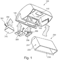
- FIG. 1 shows an exploded isometric view of a storage compartment module according to the invention.
- the storage compartment module shown here has an integral supply channel and consists of a fixed (rigid) storage compartment module housing 100, designed as a drawer housing (sandwich) or support housing (metal or CFK) for receiving the guide rails 130 for the storage compartment, and for receiving the passenger compartment.
- Service Channel (PSC) rails 140 for the Passenger Service Units 310, 320, 330 (PSUs).
- PSC Passenger Service Units 310, 320, 330
- Generous to achieve the fasteners for mounting on the aircraft structure to facilitate the mounting and alignment of the housing 100 considerably.
- Generous access openings 150 in the housing towards the supply channel are to enable simple and ergonomic connection of the PSUs to the electrical, oxygen and individual air connections at eye level.
- the storage compartment 200 itself represents in particular with its wall 210 the visible part to the cabin and conceals in the assembled state all cables and hoses of the PSUs and their back and the kinematics (guide rails and rollers) by appropriate geometric design.
- the storage compartment consists of a drawer housing (sandwich) with a total of four rollers 231, 233 for storage in the guide rails 130 of the housing.
- the PSUs functionally correspond to the common components used in the cabin, but with the advantage that neither hinged hinges nor cable or hose overlengths with appropriate abrasion protection covers and their separate holder are required for applying.
- the storage compartment described combines the realization of a complex travel path on a closed rail (one per side) with two bearing points each (ball-bearing polyamide rollers). Although this is a complex movement of the storage compartment, a maximum reduction in the number of parts is achieved by integrating all the desired functions in the shaping of a single component (guide rail).
- This guide rail itself is per storage compartment module offset in the aircraft longitudinal direction twice available, each designed as a fixed or loose bearings, which also allows luggage racks over several aircraft frame. Since these guide rails are led out of the edge surface on the sides of the housing, a simple one-man assembly of the roll-guided storage compartments via self-determination (inlet slopes) on the rails is possible.
- the rails 130 are closed by a respective locking screws and stopper plugs 120 held with fixing screws, as soon as the guide rollers 230 of a storage compartment 200 are inserted into the guide rails 130.
- the stop plugs can be provided with an elastic buffer for additional damping and end stop. Since the housing can be mounted separately from the storage compartment on the aircraft structure, the attachment of the housing is facilitated by, for example, mounting holes on the rear wall substantially. These mounting openings as well as the entire interior of the storage compartment module are protected from view after the installation of the storage compartment, which also functions as a visible part.
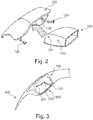
- the guide rail 130 is designed with respect to the end position so that the closed end position as close as possible to the fuselage (see FIG. 3 ), which are open as load-friendly as possible (see FIG. 4 ).
- the construct is thus suitable for optimally designing the pivoting movement and for minimizing dead spaces (swiveling ranges) and for enabling the largest possible cabin in an aircraft.
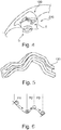
- the travel when opening is chosen so that the fulcrum is initially far from the center of gravity to the structure side, to ensure a guaranteed and fast self-opening of the storage compartment, and migrates continuously to the pivot point.
- the further travel when opening is chosen so that the fulcrum approaches the center of gravity continuously to prevent further gravitational acceleration.
- phase P2 in FIG. 6 The further travel when opening (phase P2 in FIG. 6 ) leads to a fulcrum change over the center of gravity towards the passenger.
- the speed of the storage compartment is decelerated to pay off the kinetic energy before reaching the end position.
- phase P3 in FIG. 6 The further travel when opening (phase P3 in FIG. 6 ) is now chosen so that the pivot point moves back over the center of gravity of the structure side to ensure safe storage of the storage compartment in fully open position.
- the further travel to the final closed position is further selected so that after reaching a certain kinetic energy by the previous acceleration phase, the final closure with little manual force is to be realized.
- the required hand forces thus remain in a pleasant setting.
- the physical effect, which can be used here, is explained essentially by a defined interplay between potential and kinetic energy (see FIG. 6 ).
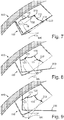
- FIGS. 7 to 9 presented in a different way.
- FIGS. 7, 8 and 9 In each case, a part of the structure 400 is shown, to which the housing 100 of the storage compartment module is attached.
- a guide rail 130 is seen, which is composed of the following segments: a first guide segment 131, in which a first roller 231 of a storage compartment 200 can engage, a connecting segment 132 through which the first roller 231 passes when the storage compartment 200th mounted, a second guide segment 133 through which the first roller 231 passes during assembly and in which a second roller 233 of the storage compartment 200 can engage, and finally a mounting segment 134, which is formed open to the front, so that the first and then the second role can be introduced during assembly in the guide rail 130.
- the FIG. 7 shows the storage compartment in the closed position.
- the FIG. 8 shows the storage compartment in partially open position.
- the FIG. 9 shows the storage compartment in fully open position.
- the instantaneous polarity curve MK and the instantaneous pole M of the respective position are indicated. In this way, it is clarified that the actual pivot point of a specific position or position of the storage compartment during the movement of the storage compartment between the closed and the open position along the instantaneous pole MK migrates.
- the shape of the instantaneous pole curve MK illustrates that an altered tilting movement is realized during the movement of the storage compartment.
- This changed tilting movement has the consequence that the force to be expended, that is, the manual force, varies depending on the position of the storage compartment.
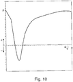
- FIG. 10 an exemplary course of the force F is shown over the opening angle ⁇ .
- the force needed to actuate the storage compartment becomes negative even in one section.
- the storage compartment moves independently, without the need for any external force.
- the curve will change or move.
- the power is in each case partially smaller, so that the operation of the storage compartment, ie an opening or closing the storage compartment, is facilitated.
- FIG. 11 shows a flowchart in which the steps of a method for installing a storage compartment according to the invention are shown schematically. It is noted that the steps of the method are merely main steps, which main steps may be differentiated or sub-divided. Also, you can also make sub-steps between the main steps be made. A sub-step is mentioned as such only if that step is important to understanding the principles of the method according to the invention.
- step S1 the housing of the storage compartment is attached to the structure of an aircraft.
- step S2 the first rollers each disposed on one side of the storage compartment are inserted into the mounting segments of the guide rails.
- step S3 the storage compartment is inserted into the housing of the storage compartment module such that the first rollers run along the mounting segment, along the second guide segment and into the connection segment.
- step S4 the second rollers are then inserted into the mounting segments.
- step S6 the open ends of the mounting segments can be closed by means of sealing plugs.
- the design of the storage compartment module enables a splitting of the module into two components, namely the housing and the storage compartment, which are separated optimally for assembly. Installation and service problems that occur in the conventional design are eliminated in this way.
- the assembly of the housing is greatly simplified by the frontal accessibility of the fastening and adjusting elements.
- the PSUs do not need to be hinged and are fixed in place before being connected to the supply lines in the aircraft structure.
- the versatility and flexibility of the supply channel is maintained, test routines of the supply channel are maintained, tolerance problems of the supply channel in the aircraft direction (structural tolerances) can be solved by tolerance panels, closed contours of the side panel, the PSC, the storage compartment housing and the storage compartment for ceiling lining are possible, Finally, a handle-less design is also possible due to the gravity-related self-opening of the storage compartment (unlocking via push-to-open).
Claims (13)
- Module de compartiment de rangement comprenant:un boîtier (100) ayant un espace de réception (180) du compartiment de rangement, dans lequel, sur les deux parois latérales de l'espace de réception du compartiment de stockage, dans chaque cas, un rail de guidage (130) est disposé, etun compartiment de rangement (200) avec deux côtés et des éléments de guidage (231, 233) disposés sur ces côtés, dans lequel les éléments de guidage comprenant des premiers rouleaux (231) et des deuxièmes rouleaux (233), dans lequel à chacun des deux côtés du compartiment de rangement sont agencés un premier rouleau et un deuxième rouleau, qui peuvent s'engager avec l'un des rails de guidage (130),dans lequel les rails de guidage étant chacun adapté de telle manière, que le compartiment de rangement peut être déplacé entre une position ouverte et une position fermée le long du rail de guidage et une force exercée par un passager pour actionner le compartiment de rangement pendant le chemin du déplacement du compartiment de rangement est réduite par le poids du compartiment de rangement.
- Module de compartiment de rangement selon la revendication 1, dans lequel le compartiment de rangement (200) peut être déplacé entre une position ouverte et une position fermée le long des rails de guidage (130) au moins partiellement uniquement par de son propre poids.
- Module de compartiment de rangement selon la revendication 1, dans lequel chaque rail de guidage comprend un premier segment de guidage (131) pour guidage du premier rouleau, un second segment de guidage (133) pour guidage du second rouleau, un segment de liaison entre le premier et le second segment de guidage et un segment de montage (134) pour insertion des rouleaux dans les rails de guidage.
- Module de compartiment de rangement selon la revendication 3, dans lequel les premiers rouleaux (231) sont agencés de telle manière pour venir en prise avec les premiers segments de guidage (131) et les seconds rouleaux (233) sont agencés de telle manière pour venir en prise avec les seconds segments de guidage (133) quand le compartiment de rangement (200) est installé dans le boîtier (100).
- Module de compartiment de rangement selon la revendication 1, comprenant en outre un bouchon de fermeture (120) adapté pour fermer une extrémité d'un rail de guidage (130).
- Module de compartiment de rangement selon la revendication 1, comprenant en outre un verrou de sorte que le compartiment de stockage (200) peut être verrouillé dans une position fermée dans le boîtier (100).
- Module de rangement selon la revendication 1, dans lequel le chemin de déplacement du compartiment de rangement (200) est déterminé de sorte que dans chaque position du compartiment de rangement entre une position ouverte et fermée, un espace sensiblement constant entre un coté extérieur (210) du compartiment de rangement et un bord du boîtier (100) est formé.
- Module de compartiment de rangement selon la revendication 1, dans lequel le module de compartiment de rangement peut être intégré positivement dans le revêtement intérieur de l'aéronef.
- Module de compartiment de rangement selon la revendication 1, comprenant en outre un canal d'alimentation de passager (160) et au moins un élément d'alimentation de passager (300), dans lequel le au moins un élément d'alimentation de passager est un groupe comprenant: boîtier d'alimentation d'oxygène, enceinte, prise casque, lumière, sortie d'air pour l'alimentation en air, prise USB, prise d'ordinateur et capot.
- Utilisation d'un module de compartiment de rangement selon l'une des revendications 1 à 9 dans un aéronef ou un véhicule.
- Aéronef avec un module de compartiment de rangement selon l'une des revendications 1 à 9.
- Procédé d'installation d'un module de compartiment de rangement selon l'une des revendications 3 à 9 dans un aéronef, le procédé comprenant les étapes:- Fixation du boîtier (100) du module de compartiment de rangement sur la structure (400) de l'aéronef,Engagement des premiers rouleaux (231) dans les segments de montage (134) des rails de guidage (130),
Insertion du compartiment de rangement (200) dans l'espace de réception du compartiment de rangement (180), dans lequel les premiers rouleaux (231) se déplacent le long des rails de guidage (130),
Engagement des seconds rouleaux (233) dans les segments de montage (134) et l'insertion supplémentaire du compartiment de rangement (200) jusqu'à ce que les premiers rouleaux (231) sont disposés dans les premiers segments de guidage (131) et les seconds rouleaux (231) sont disposés dans les second segments de guidage (133). - Procédé selon la revendication 12, comprenant en outre l'étape de:- Fermeture des rails de guidage (130).
Applications Claiming Priority (3)
| Application Number | Priority Date | Filing Date | Title |
|---|---|---|---|
| US28016509P | 2009-10-30 | 2009-10-30 | |
| DE102009051363A DE102009051363A1 (de) | 2009-10-30 | 2009-10-30 | Staufachmodul mit beweglichem Staufach |
| PCT/EP2010/065799 WO2011051149A2 (fr) | 2009-10-30 | 2010-10-20 | Module compartiment de rangement doté d'un compartiment de rangement mobile |
Publications (2)
| Publication Number | Publication Date |
|---|---|
| EP2493761A2 EP2493761A2 (fr) | 2012-09-05 |
| EP2493761B1 true EP2493761B1 (fr) | 2018-05-30 |
Family
ID=43828763
Family Applications (1)
| Application Number | Title | Priority Date | Filing Date |
|---|---|---|---|
| EP10771083.2A Not-in-force EP2493761B1 (fr) | 2009-10-30 | 2010-10-20 | Module compartiment de rangement doté d'un compartiment de rangement mobile |
Country Status (4)
| Country | Link |
|---|---|
| US (1) | US8517308B2 (fr) |
| EP (1) | EP2493761B1 (fr) |
| DE (1) | DE102009051363A1 (fr) |
| WO (1) | WO2011051149A2 (fr) |
Families Citing this family (27)
| Publication number | Priority date | Publication date | Assignee | Title |
|---|---|---|---|---|
| DE102007030331A1 (de) * | 2007-06-29 | 2009-01-02 | Airbus Deutschland Gmbh | Staufachmodul für einen Innenraum eines Flugzeugs |
| DE102009051363A1 (de) * | 2009-10-30 | 2011-05-05 | Airbus Operations Gmbh | Staufachmodul mit beweglichem Staufach |
| DE102009058849B4 (de) * | 2009-12-18 | 2012-03-08 | Airbus Operations Gmbh | Systemkomponentenmodul und Verfahren zur Montage eines Systemkomponentenmoduls |
| DE102010018569A1 (de) * | 2010-04-28 | 2011-11-03 | Airbus Operations Gmbh | Trägerstruktur zum Einsatz in einer Luftzufuhranordnung sowie Versorgungssystem mit einer solchen Trägerstruktur und Verfahren zur Konfiguration |
| DE102010026805B4 (de) * | 2010-07-10 | 2016-08-11 | Diehl Aerospace Gmbh | Einrichtung zum Versorgen von Verbrauchern im Überkopfbereich einer Passagierkabine, insbesondere in Verkehrsflugzeugen |
| DE102011105005A1 (de) * | 2011-06-20 | 2012-12-20 | Airbus Operations Gmbh | Bewegliches Staufach |
| DE102011108895A1 (de) * | 2011-07-29 | 2013-01-31 | Airbus Operations Gmbh | Tragende Struktur für bewegliches Staufach |
| DE102011110010A1 (de) * | 2011-08-11 | 2013-02-14 | Airbus Operations Gmbh | Passagierversorgungsmodul mit integrierter Kabinenbeleuchtung |
| US8702037B2 (en) * | 2011-09-28 | 2014-04-22 | The Boeing Company | Translating stowage bin and method of assembly |
| US10029794B2 (en) | 2012-02-14 | 2018-07-24 | C&D Zodiac, Inc. | Outboard rotating pivot bin assembly |
| US9789963B2 (en) | 2012-02-14 | 2017-10-17 | C&D Zodiac, Inc. | Pivot bin assembly with minimal force required for closing |
| US9365291B2 (en) | 2012-02-14 | 2016-06-14 | C&D Zodiac, Inc. | Passenger service unit pod assembly |
| US9162617B2 (en) * | 2012-02-14 | 2015-10-20 | C&D Zodiac, Inc. | Pivot bin assembly |
| US8955805B2 (en) | 2012-02-14 | 2015-02-17 | C&D Zodiac, Inc. | Pivot bin assembly |
| DE102012009632A1 (de) | 2012-05-14 | 2013-11-14 | Airbus Operations Gmbh | Modulare Überkopf-Gepäckablage |
| USD784905S1 (en) | 2013-02-12 | 2017-04-25 | C&D Zodiac, Inc. | Storage bin for aircraft |
| CN105189289B (zh) * | 2013-02-13 | 2016-09-14 | C&D佐迪阿克公司 | 枢转仓组件 |
| CA151587S (en) | 2013-06-10 | 2015-11-30 | Inflight Invest Inc | Aircraft passenger control unit with electric power outlet |
| EP2832642A1 (fr) * | 2013-07-31 | 2015-02-04 | Zodiac Aerotechnics | Dispositif de stockage comprenant un compartiment à bagage et une unité d'oxygène d'urgence |
| US9187177B2 (en) | 2013-08-20 | 2015-11-17 | The Boeing Company | Translating stowage bin and method of assembly |
| US9578962B2 (en) | 2013-08-20 | 2017-02-28 | The Boeing Company | Translating stowage bin and method of assembly |
| EP2879258B1 (fr) * | 2013-11-28 | 2016-07-13 | Airbus Operations GmbH | Système de gestion de puissance d'aéronef et procédé de gestion d'alimentation dans un aéronef |
| EP2879260B1 (fr) | 2013-11-28 | 2017-04-05 | Airbus Operations GmbH | Système de gestion de puissance d'aéronef et procédé de gestion d'alimentation dans un aéronef |
| USD875641S1 (en) | 2015-02-02 | 2020-02-18 | C&D Zodiac, Inc. | Personal service unit |
| USD784904S1 (en) | 2015-02-02 | 2017-04-25 | C&D Zodiac, Inc. | Aircraft passenger service unit |
| US9630718B2 (en) * | 2015-02-06 | 2017-04-25 | The Boeing Company | Variable opening overhead stowage bins and related methods |
| US9731826B2 (en) | 2015-12-07 | 2017-08-15 | C&D Zodiac, Inc. | Storage bin with luggage positioning protrusions |
Citations (1)
| Publication number | Priority date | Publication date | Assignee | Title |
|---|---|---|---|---|
| EP1116651A2 (fr) * | 2000-01-13 | 2001-07-18 | EADS Airbus GmbH | Coffre de rangement avec boítier abaissable pour aéronef |
Family Cites Families (31)
| Publication number | Priority date | Publication date | Assignee | Title |
|---|---|---|---|---|
| DE9214592U1 (fr) * | 1992-10-28 | 1993-02-11 | Deutsche Aerospace Airbus Gmbh, 2000 Hamburg, De | |
| DE4301681C1 (de) * | 1993-01-22 | 1994-10-20 | Deutsche Aerospace Airbus | Rohrverzweigung zwischen einer Luftleitung und einer Luftdusche |
| US5716027A (en) * | 1994-12-23 | 1998-02-10 | Hexcel Corporation | Retrofit luggage bin assemblies compatible with existing aircraft bin supports |
| US5549258A (en) * | 1994-12-23 | 1996-08-27 | Heath Tecna Aerospace Company | Retrofit luggage bin assembly compatible with existing aircraft bin supports |
| DE19502658C1 (de) * | 1995-01-28 | 1996-03-28 | Daimler Benz Aerospace Airbus | Anordnung zum Versorgen von Passagieren in einer Passagierkabine, insbesondere in einem Flugzeug |
| US5687929A (en) * | 1995-06-29 | 1997-11-18 | Hexcel Corporation | Extensions for storage bins |
| EP0795468B1 (fr) * | 1996-03-15 | 2002-11-27 | Airbus Deutschland GmbH | Système d'éclairage pour une cabine de passagers, spécialement une cabine d'avion |
| US6246449B1 (en) * | 1996-08-16 | 2001-06-12 | Rosen Products Llc | Display unit |
| US5842668A (en) * | 1997-02-27 | 1998-12-01 | Hexcel Corporation | Quick fit overhead stowage compartment |
| DE29907980U1 (de) * | 1999-05-05 | 1999-07-08 | Hettich Heinze Gmbh & Co Kg | Führungseinrichtung für Schiebetürelemente eines Möbels |
| DE19926776B4 (de) * | 1999-06-11 | 2004-07-22 | Airbus Deutschland Gmbh | Funktionseinheit für Passagierkabinen, insbesondere für Flugzeugpassagierkabinen |
| DE19946629B4 (de) * | 1999-09-29 | 2012-05-10 | Volkswagen Ag | Staukastenvorrichtung, insbesondere Dachstaukastenvorrichtung für ein Kraftfahrzeug |
| UA29554C2 (uk) * | 1999-12-20 | 2000-11-15 | Товариство З Обмеженою Відповідальністю "Інтер Амі" | Багажна полиця літака |
| US6409242B1 (en) * | 2000-11-14 | 2002-06-25 | Chung L. Chang | Flat thin screen T/V monitor automotive roof mount |
| DE10063932C2 (de) * | 2000-12-20 | 2002-11-28 | Airbus Gmbh | Gepäckablage mit einem absenkbaren Gepäckfach, insbesondere für eine Flugzeugpassagierkabine |
| US6633347B2 (en) * | 2001-01-02 | 2003-10-14 | Alpine Electronics, Inc. | Display assembly having display supported on casing to be controllable in attitude |
| US6874730B2 (en) * | 2001-09-03 | 2005-04-05 | Goodrich Hella Aerospace Lighting Systems Gmbh | Covering element for the interior of a vehicle, particularly an aircraft |
| AT413812B (de) * | 2001-10-17 | 2006-06-15 | Fischer Adv Components Gmbh | Aufhängevorrichtung für absenkbare gebäckablagebehälter |
| US6619716B1 (en) * | 2002-03-28 | 2003-09-16 | Lear Corporation | Integrated vehicle console system |
| DE102004043910B4 (de) * | 2004-09-10 | 2007-05-16 | Safa Kirma | Haltesystem für ein Gepäckfach |
| US7309045B2 (en) * | 2004-11-01 | 2007-12-18 | The Boeing Company | Modular vehicle units, including aircraft interior storage units, and associated methods |
| DE102005033259B4 (de) * | 2005-07-15 | 2012-03-08 | Airbus Operations Gmbh | Notöffnungsvorrichtung für ein Gepäckfach mit einer absenkbaren Schale |
| US7883055B2 (en) * | 2005-10-28 | 2011-02-08 | Airbus | Pivoting baggage rack intended for an aircraft cabin |
| DE102006045189B4 (de) * | 2006-09-25 | 2008-11-27 | Airbus Deutschland Gmbh | Kraftunterstützungssystem |
| DE102007028858A1 (de) | 2007-06-22 | 2009-01-02 | Wincor Nixdorf International Gmbh | Wertscheinautomat |
| DE102007030331A1 (de) | 2007-06-29 | 2009-01-02 | Airbus Deutschland Gmbh | Staufachmodul für einen Innenraum eines Flugzeugs |
| DE102008026116B4 (de) * | 2008-05-30 | 2014-03-06 | Airbus Operations Gmbh | Anordnung zum Unterbringen von Gegenständen in einer Kabine eines Fahrzeugs |
| DE102008051240B3 (de) * | 2008-10-10 | 2010-09-30 | Airbus Deutschland Gmbh | Vorrichtung zur Aufnahme von Gepäck in einer Passagierkabine eines Flugzeuges |
| DE102008058271A1 (de) * | 2008-11-20 | 2010-05-27 | Airbus Deutschland Gmbh | Versorgungseinheit für flexible Versorgungskanäle |
| DE102009051363A1 (de) * | 2009-10-30 | 2011-05-05 | Airbus Operations Gmbh | Staufachmodul mit beweglichem Staufach |
| DE102009051362A1 (de) * | 2009-10-30 | 2011-05-05 | Airbus Operations Gmbh | Staufachmodul mit integralem Versorgungskanal für optimierte Montage |
-
2009
- 2009-10-30 DE DE102009051363A patent/DE102009051363A1/de not_active Withdrawn
-
2010
- 2010-10-20 WO PCT/EP2010/065799 patent/WO2011051149A2/fr active Application Filing
- 2010-10-20 EP EP10771083.2A patent/EP2493761B1/fr not_active Not-in-force
-
2012
- 2012-04-30 US US13/460,090 patent/US8517308B2/en active Active
Patent Citations (1)
| Publication number | Priority date | Publication date | Assignee | Title |
|---|---|---|---|---|
| EP1116651A2 (fr) * | 2000-01-13 | 2001-07-18 | EADS Airbus GmbH | Coffre de rangement avec boítier abaissable pour aéronef |
Also Published As
| Publication number | Publication date |
|---|---|
| US8517308B2 (en) | 2013-08-27 |
| US20120228426A1 (en) | 2012-09-13 |
| WO2011051149A2 (fr) | 2011-05-05 |
| DE102009051363A1 (de) | 2011-05-05 |
| EP2493761A2 (fr) | 2012-09-05 |
| WO2011051149A3 (fr) | 2011-08-18 |
Similar Documents
| Publication | Publication Date | Title |
|---|---|---|
| EP2493761B1 (fr) | Module compartiment de rangement doté d'un compartiment de rangement mobile | |
| EP2493760B1 (fr) | Module compartiment de rangement doté d'un canal de service passagers intégré de montage optimisé | |
| EP2440457B1 (fr) | Système et procédé de fabrication d'une cabine de véhicule | |
| EP2536628B1 (fr) | Compartiment de rangement sans boîtier | |
| DE102017131130B4 (de) | Befestigungssystem zum Befestigen einer Komponente an einer Rumpfstruktur | |
| DE102008051240B3 (de) | Vorrichtung zur Aufnahme von Gepäck in einer Passagierkabine eines Flugzeuges | |
| DE102007030330B4 (de) | Schwenkbarer Geräteträger in Kombination mit modifizierter Gepäckablage | |
| EP2495150B1 (fr) | Dépôt de bagage modulaire | |
| DE102011105035A1 (de) | Ablagefach-Vorrichtung | |
| DE102012009632A1 (de) | Modulare Überkopf-Gepäckablage | |
| DE102010005905B4 (de) | Überkopfgepäckfach mit einer Halterung für eine Bedieneinheit | |
| EP3233635A1 (fr) | Compartiment à bagages de plafond pour avions | |
| DE102014101895A1 (de) | Inneneinrichtungskomponente für ein Fahrzeug mit modularer Passagierversorgungseinheit | |
| DE102015116798B4 (de) | Raumoptimierte Kabinenanordnung für ein Fahrzeug sowie eine Passagierkabine mit einer Mehrzahl von Sitzen und einer solchen Kabinenanordnung | |
| EP2335992A1 (fr) | Cabine de conduite modulaire pour véhicule ferroviaire et procédé de fabrication | |
| EP3426527B1 (fr) | Véhicule pour le transport public de personnes | |
| EP2540616B1 (fr) | Mécanisme de fermeture pour portes coulissantes assistées | |
| DE102008025232A1 (de) | Verriegelungsmechanismus für ein Flugzeuginnenausstattungsbauteil | |
| DE102012015518A1 (de) | Zentralsitzanlage | |
| AT520638B1 (de) | Befestigung für Innenausbauteile von Fahrzeugen | |
| DE102016103825A1 (de) | Anordnung in einer Fahrzeugkabine mit einem Kabinenmonument mit zwei Zugangsöffnungen an zwei eine Schnittfläche ausbildenden Gängen | |
| DE102010051217A1 (de) | Flugzeugtürrahmenverkleidung zur optischen Abdeckung eines Türbereichs in einem Flugzeug | |
| EP3205533B1 (fr) | Dispositif de rangement pour un siège | |
| DE102016217319A1 (de) | Deckeneinheit für ein Fahrzeug | |
| DE102016104927A1 (de) | Anordnung in einer Kabine eines Flugzeugs mit einer durch ein Kabinenmonument selektiv bereitstellbaren Nische |
Legal Events
| Date | Code | Title | Description |
|---|---|---|---|
| PUAI | Public reference made under article 153(3) epc to a published international application that has entered the european phase |
Free format text: ORIGINAL CODE: 0009012 |
|
| 17P | Request for examination filed |
Effective date: 20120423 |
|
| AK | Designated contracting states |
Kind code of ref document: A2 Designated state(s): AL AT BE BG CH CY CZ DE DK EE ES FI FR GB GR HR HU IE IS IT LI LT LU LV MC MK MT NL NO PL PT RO RS SE SI SK SM TR |
|
| DAX | Request for extension of the european patent (deleted) | ||
| 17Q | First examination report despatched |
Effective date: 20130430 |
|
| STAA | Information on the status of an ep patent application or granted ep patent |
Free format text: STATUS: EXAMINATION IS IN PROGRESS |
|
| GRAP | Despatch of communication of intention to grant a patent |
Free format text: ORIGINAL CODE: EPIDOSNIGR1 |
|
| STAA | Information on the status of an ep patent application or granted ep patent |
Free format text: STATUS: GRANT OF PATENT IS INTENDED |
|
| INTG | Intention to grant announced |
Effective date: 20180119 |
|
| INTG | Intention to grant announced |
Effective date: 20180119 |
|
| GRAS | Grant fee paid |
Free format text: ORIGINAL CODE: EPIDOSNIGR3 |
|
| GRAA | (expected) grant |
Free format text: ORIGINAL CODE: 0009210 |
|
| STAA | Information on the status of an ep patent application or granted ep patent |
Free format text: STATUS: THE PATENT HAS BEEN GRANTED |
|
| AK | Designated contracting states |
Kind code of ref document: B1 Designated state(s): AL AT BE BG CH CY CZ DE DK EE ES FI FR GB GR HR HU IE IS IT LI LT LU LV MC MK MT NL NO PL PT RO RS SE SI SK SM TR |
|
| REG | Reference to a national code |
Ref country code: GB Ref legal event code: FG4D Free format text: NOT ENGLISH |
|
| REG | Reference to a national code |
Ref country code: CH Ref legal event code: EP |
|
| REG | Reference to a national code |
Ref country code: AT Ref legal event code: REF Ref document number: 1003348 Country of ref document: AT Kind code of ref document: T Effective date: 20180615 |
|
| REG | Reference to a national code |
Ref country code: IE Ref legal event code: FG4D Free format text: LANGUAGE OF EP DOCUMENT: GERMAN |
|
| REG | Reference to a national code |
Ref country code: DE Ref legal event code: R096 Ref document number: 502010015032 Country of ref document: DE |
|
| REG | Reference to a national code |
Ref country code: NL Ref legal event code: MP Effective date: 20180530 |
|
| REG | Reference to a national code |
Ref country code: LT Ref legal event code: MG4D |
|
| REG | Reference to a national code |
Ref country code: FR Ref legal event code: PLFP Year of fee payment: 9 |
|
| PG25 | Lapsed in a contracting state [announced via postgrant information from national office to epo] |
Ref country code: ES Free format text: LAPSE BECAUSE OF FAILURE TO SUBMIT A TRANSLATION OF THE DESCRIPTION OR TO PAY THE FEE WITHIN THE PRESCRIBED TIME-LIMIT Effective date: 20180530 Ref country code: CY Free format text: LAPSE BECAUSE OF FAILURE TO SUBMIT A TRANSLATION OF THE DESCRIPTION OR TO PAY THE FEE WITHIN THE PRESCRIBED TIME-LIMIT Effective date: 20180530 Ref country code: FI Free format text: LAPSE BECAUSE OF FAILURE TO SUBMIT A TRANSLATION OF THE DESCRIPTION OR TO PAY THE FEE WITHIN THE PRESCRIBED TIME-LIMIT Effective date: 20180530 Ref country code: LT Free format text: LAPSE BECAUSE OF FAILURE TO SUBMIT A TRANSLATION OF THE DESCRIPTION OR TO PAY THE FEE WITHIN THE PRESCRIBED TIME-LIMIT Effective date: 20180530 Ref country code: BG Free format text: LAPSE BECAUSE OF FAILURE TO SUBMIT A TRANSLATION OF THE DESCRIPTION OR TO PAY THE FEE WITHIN THE PRESCRIBED TIME-LIMIT Effective date: 20180830 Ref country code: SE Free format text: LAPSE BECAUSE OF FAILURE TO SUBMIT A TRANSLATION OF THE DESCRIPTION OR TO PAY THE FEE WITHIN THE PRESCRIBED TIME-LIMIT Effective date: 20180530 Ref country code: NO Free format text: LAPSE BECAUSE OF FAILURE TO SUBMIT A TRANSLATION OF THE DESCRIPTION OR TO PAY THE FEE WITHIN THE PRESCRIBED TIME-LIMIT Effective date: 20180830 |
|
| PG25 | Lapsed in a contracting state [announced via postgrant information from national office to epo] |
Ref country code: GR Free format text: LAPSE BECAUSE OF FAILURE TO SUBMIT A TRANSLATION OF THE DESCRIPTION OR TO PAY THE FEE WITHIN THE PRESCRIBED TIME-LIMIT Effective date: 20180831 Ref country code: RS Free format text: LAPSE BECAUSE OF FAILURE TO SUBMIT A TRANSLATION OF THE DESCRIPTION OR TO PAY THE FEE WITHIN THE PRESCRIBED TIME-LIMIT Effective date: 20180530 Ref country code: HR Free format text: LAPSE BECAUSE OF FAILURE TO SUBMIT A TRANSLATION OF THE DESCRIPTION OR TO PAY THE FEE WITHIN THE PRESCRIBED TIME-LIMIT Effective date: 20180530 Ref country code: LV Free format text: LAPSE BECAUSE OF FAILURE TO SUBMIT A TRANSLATION OF THE DESCRIPTION OR TO PAY THE FEE WITHIN THE PRESCRIBED TIME-LIMIT Effective date: 20180530 |
|
| PG25 | Lapsed in a contracting state [announced via postgrant information from national office to epo] |
Ref country code: NL Free format text: LAPSE BECAUSE OF FAILURE TO SUBMIT A TRANSLATION OF THE DESCRIPTION OR TO PAY THE FEE WITHIN THE PRESCRIBED TIME-LIMIT Effective date: 20180530 |
|
| PG25 | Lapsed in a contracting state [announced via postgrant information from national office to epo] |
Ref country code: RO Free format text: LAPSE BECAUSE OF FAILURE TO SUBMIT A TRANSLATION OF THE DESCRIPTION OR TO PAY THE FEE WITHIN THE PRESCRIBED TIME-LIMIT Effective date: 20180530 Ref country code: CZ Free format text: LAPSE BECAUSE OF FAILURE TO SUBMIT A TRANSLATION OF THE DESCRIPTION OR TO PAY THE FEE WITHIN THE PRESCRIBED TIME-LIMIT Effective date: 20180530 Ref country code: SK Free format text: LAPSE BECAUSE OF FAILURE TO SUBMIT A TRANSLATION OF THE DESCRIPTION OR TO PAY THE FEE WITHIN THE PRESCRIBED TIME-LIMIT Effective date: 20180530 Ref country code: PL Free format text: LAPSE BECAUSE OF FAILURE TO SUBMIT A TRANSLATION OF THE DESCRIPTION OR TO PAY THE FEE WITHIN THE PRESCRIBED TIME-LIMIT Effective date: 20180530 Ref country code: EE Free format text: LAPSE BECAUSE OF FAILURE TO SUBMIT A TRANSLATION OF THE DESCRIPTION OR TO PAY THE FEE WITHIN THE PRESCRIBED TIME-LIMIT Effective date: 20180530 Ref country code: DK Free format text: LAPSE BECAUSE OF FAILURE TO SUBMIT A TRANSLATION OF THE DESCRIPTION OR TO PAY THE FEE WITHIN THE PRESCRIBED TIME-LIMIT Effective date: 20180530 |
|
| PG25 | Lapsed in a contracting state [announced via postgrant information from national office to epo] |
Ref country code: IT Free format text: LAPSE BECAUSE OF FAILURE TO SUBMIT A TRANSLATION OF THE DESCRIPTION OR TO PAY THE FEE WITHIN THE PRESCRIBED TIME-LIMIT Effective date: 20180530 Ref country code: SM Free format text: LAPSE BECAUSE OF FAILURE TO SUBMIT A TRANSLATION OF THE DESCRIPTION OR TO PAY THE FEE WITHIN THE PRESCRIBED TIME-LIMIT Effective date: 20180530 |
|
| REG | Reference to a national code |
Ref country code: DE Ref legal event code: R097 Ref document number: 502010015032 Country of ref document: DE |
|
| PLBE | No opposition filed within time limit |
Free format text: ORIGINAL CODE: 0009261 |
|
| STAA | Information on the status of an ep patent application or granted ep patent |
Free format text: STATUS: NO OPPOSITION FILED WITHIN TIME LIMIT |
|
| 26N | No opposition filed |
Effective date: 20190301 |
|
| PG25 | Lapsed in a contracting state [announced via postgrant information from national office to epo] |
Ref country code: SI Free format text: LAPSE BECAUSE OF FAILURE TO SUBMIT A TRANSLATION OF THE DESCRIPTION OR TO PAY THE FEE WITHIN THE PRESCRIBED TIME-LIMIT Effective date: 20180530 |
|
| REG | Reference to a national code |
Ref country code: CH Ref legal event code: PL |
|
| REG | Reference to a national code |
Ref country code: BE Ref legal event code: MM Effective date: 20181031 |
|
| PG25 | Lapsed in a contracting state [announced via postgrant information from national office to epo] |
Ref country code: LU Free format text: LAPSE BECAUSE OF NON-PAYMENT OF DUE FEES Effective date: 20181020 Ref country code: MC Free format text: LAPSE BECAUSE OF FAILURE TO SUBMIT A TRANSLATION OF THE DESCRIPTION OR TO PAY THE FEE WITHIN THE PRESCRIBED TIME-LIMIT Effective date: 20180530 |
|
| REG | Reference to a national code |
Ref country code: IE Ref legal event code: MM4A |
|
| PG25 | Lapsed in a contracting state [announced via postgrant information from national office to epo] |
Ref country code: LI Free format text: LAPSE BECAUSE OF NON-PAYMENT OF DUE FEES Effective date: 20181031 Ref country code: CH Free format text: LAPSE BECAUSE OF NON-PAYMENT OF DUE FEES Effective date: 20181031 Ref country code: BE Free format text: LAPSE BECAUSE OF NON-PAYMENT OF DUE FEES Effective date: 20181031 |
|
| PG25 | Lapsed in a contracting state [announced via postgrant information from national office to epo] |
Ref country code: IE Free format text: LAPSE BECAUSE OF NON-PAYMENT OF DUE FEES Effective date: 20181020 |
|
| PG25 | Lapsed in a contracting state [announced via postgrant information from national office to epo] |
Ref country code: AL Free format text: LAPSE BECAUSE OF FAILURE TO SUBMIT A TRANSLATION OF THE DESCRIPTION OR TO PAY THE FEE WITHIN THE PRESCRIBED TIME-LIMIT Effective date: 20180530 |
|
| REG | Reference to a national code |
Ref country code: AT Ref legal event code: MM01 Ref document number: 1003348 Country of ref document: AT Kind code of ref document: T Effective date: 20181020 |
|
| PG25 | Lapsed in a contracting state [announced via postgrant information from national office to epo] |
Ref country code: AT Free format text: LAPSE BECAUSE OF NON-PAYMENT OF DUE FEES Effective date: 20181020 Ref country code: MT Free format text: LAPSE BECAUSE OF FAILURE TO SUBMIT A TRANSLATION OF THE DESCRIPTION OR TO PAY THE FEE WITHIN THE PRESCRIBED TIME-LIMIT Effective date: 20180530 |
|
| PGFP | Annual fee paid to national office [announced via postgrant information from national office to epo] |
Ref country code: DE Payment date: 20191021 Year of fee payment: 10 |
|
| PGFP | Annual fee paid to national office [announced via postgrant information from national office to epo] |
Ref country code: FR Payment date: 20191028 Year of fee payment: 10 |
|
| PG25 | Lapsed in a contracting state [announced via postgrant information from national office to epo] |
Ref country code: TR Free format text: LAPSE BECAUSE OF FAILURE TO SUBMIT A TRANSLATION OF THE DESCRIPTION OR TO PAY THE FEE WITHIN THE PRESCRIBED TIME-LIMIT Effective date: 20180530 |
|
| PGFP | Annual fee paid to national office [announced via postgrant information from national office to epo] |
Ref country code: GB Payment date: 20191021 Year of fee payment: 10 |
|
| PG25 | Lapsed in a contracting state [announced via postgrant information from national office to epo] |
Ref country code: PT Free format text: LAPSE BECAUSE OF FAILURE TO SUBMIT A TRANSLATION OF THE DESCRIPTION OR TO PAY THE FEE WITHIN THE PRESCRIBED TIME-LIMIT Effective date: 20180530 |
|
| PG25 | Lapsed in a contracting state [announced via postgrant information from national office to epo] |
Ref country code: HU Free format text: LAPSE BECAUSE OF FAILURE TO SUBMIT A TRANSLATION OF THE DESCRIPTION OR TO PAY THE FEE WITHIN THE PRESCRIBED TIME-LIMIT; INVALID AB INITIO Effective date: 20101020 Ref country code: MK Free format text: LAPSE BECAUSE OF NON-PAYMENT OF DUE FEES Effective date: 20180530 |
|
| PG25 | Lapsed in a contracting state [announced via postgrant information from national office to epo] |
Ref country code: IS Free format text: LAPSE BECAUSE OF FAILURE TO SUBMIT A TRANSLATION OF THE DESCRIPTION OR TO PAY THE FEE WITHIN THE PRESCRIBED TIME-LIMIT Effective date: 20180930 |
|
| REG | Reference to a national code |
Ref country code: DE Ref legal event code: R119 Ref document number: 502010015032 Country of ref document: DE |
|
| GBPC | Gb: european patent ceased through non-payment of renewal fee |
Effective date: 20201020 |
|
| PG25 | Lapsed in a contracting state [announced via postgrant information from national office to epo] |
Ref country code: DE Free format text: LAPSE BECAUSE OF NON-PAYMENT OF DUE FEES Effective date: 20210501 Ref country code: FR Free format text: LAPSE BECAUSE OF NON-PAYMENT OF DUE FEES Effective date: 20201031 |
|
| PG25 | Lapsed in a contracting state [announced via postgrant information from national office to epo] |
Ref country code: GB Free format text: LAPSE BECAUSE OF NON-PAYMENT OF DUE FEES Effective date: 20201020 |