EP2493341B2 - A smoking system having a liquid storage portion and improved airflow characteristics - Google Patents
A smoking system having a liquid storage portion and improved airflow characteristics Download PDFInfo
- Publication number
- EP2493341B2 EP2493341B2 EP10781821.3A EP10781821A EP2493341B2 EP 2493341 B2 EP2493341 B2 EP 2493341B2 EP 10781821 A EP10781821 A EP 10781821A EP 2493341 B2 EP2493341 B2 EP 2493341B2
- Authority
- EP
- European Patent Office
- Prior art keywords
- capillary wick
- air flow
- smoking system
- housing
- insert
- Prior art date
- Legal status (The legal status is an assumption and is not a legal conclusion. Google has not performed a legal analysis and makes no representation as to the accuracy of the status listed.)
- Active
Links
- 230000000391 smoking effect Effects 0.000 title claims description 213
- 239000007788 liquid Substances 0.000 title claims description 91
- 238000003860 storage Methods 0.000 title description 24
- 238000010438 heat treatment Methods 0.000 claims description 212
- 239000000443 aerosol Substances 0.000 claims description 193
- 239000002245 particle Substances 0.000 claims description 70
- 238000011144 upstream manufacturing Methods 0.000 claims description 54
- 230000005465 channeling Effects 0.000 claims description 2
- 239000003570 air Substances 0.000 description 388
- 239000000463 material Substances 0.000 description 17
- 238000001746 injection moulding Methods 0.000 description 15
- 238000003754 machining Methods 0.000 description 15
- 238000009833 condensation Methods 0.000 description 14
- 230000005494 condensation Effects 0.000 description 14
- 230000007423 decrease Effects 0.000 description 14
- 230000015572 biosynthetic process Effects 0.000 description 13
- 229920006395 saturated elastomer Polymers 0.000 description 8
- 230000008901 benefit Effects 0.000 description 7
- 230000009471 action Effects 0.000 description 6
- -1 aluminium- titanium- zirconium- Chemical compound 0.000 description 6
- 238000001514 detection method Methods 0.000 description 6
- 229910052751 metal Inorganic materials 0.000 description 6
- 239000002184 metal Substances 0.000 description 6
- 239000012141 concentrate Substances 0.000 description 5
- OKTJSMMVPCPJKN-UHFFFAOYSA-N Carbon Chemical compound [C] OKTJSMMVPCPJKN-UHFFFAOYSA-N 0.000 description 4
- 229910045601 alloy Inorganic materials 0.000 description 4
- 239000000956 alloy Substances 0.000 description 4
- 239000012080 ambient air Substances 0.000 description 4
- 239000000919 ceramic Substances 0.000 description 4
- 230000008859 change Effects 0.000 description 4
- 239000002131 composite material Substances 0.000 description 4
- 230000000694 effects Effects 0.000 description 4
- 150000002739 metals Chemical class 0.000 description 4
- 230000000704 physical effect Effects 0.000 description 4
- PXHVJJICTQNCMI-UHFFFAOYSA-N Nickel Chemical compound [Ni] PXHVJJICTQNCMI-UHFFFAOYSA-N 0.000 description 3
- 241000208125 Nicotiana Species 0.000 description 3
- 235000002637 Nicotiana tabacum Nutrition 0.000 description 3
- DNIAPMSPPWPWGF-UHFFFAOYSA-N Propylene glycol Chemical compound CC(O)CO DNIAPMSPPWPWGF-UHFFFAOYSA-N 0.000 description 3
- 230000001133 acceleration Effects 0.000 description 3
- 238000009835 boiling Methods 0.000 description 3
- 230000015556 catabolic process Effects 0.000 description 3
- 238000006731 degradation reaction Methods 0.000 description 3
- 238000009826 distribution Methods 0.000 description 3
- 229910002804 graphite Inorganic materials 0.000 description 3
- 239000010439 graphite Substances 0.000 description 3
- 229910001092 metal group alloy Inorganic materials 0.000 description 3
- BASFCYQUMIYNBI-UHFFFAOYSA-N platinum Chemical group [Pt] BASFCYQUMIYNBI-UHFFFAOYSA-N 0.000 description 3
- LFQSCWFLJHTTHZ-UHFFFAOYSA-N Ethanol Chemical compound CCO LFQSCWFLJHTTHZ-UHFFFAOYSA-N 0.000 description 2
- PEDCQBHIVMGVHV-UHFFFAOYSA-N Glycerine Chemical compound OCC(O)CO PEDCQBHIVMGVHV-UHFFFAOYSA-N 0.000 description 2
- XEEYBQQBJWHFJM-UHFFFAOYSA-N Iron Chemical compound [Fe] XEEYBQQBJWHFJM-UHFFFAOYSA-N 0.000 description 2
- HBBGRARXTFLTSG-UHFFFAOYSA-N Lithium ion Chemical compound [Li+] HBBGRARXTFLTSG-UHFFFAOYSA-N 0.000 description 2
- 239000004696 Poly ether ether ketone Substances 0.000 description 2
- QVGXLLKOCUKJST-UHFFFAOYSA-N atomic oxygen Chemical compound [O] QVGXLLKOCUKJST-UHFFFAOYSA-N 0.000 description 2
- GUTLYIVDDKVIGB-UHFFFAOYSA-N cobalt atom Chemical compound [Co] GUTLYIVDDKVIGB-UHFFFAOYSA-N 0.000 description 2
- 230000003247 decreasing effect Effects 0.000 description 2
- 238000001914 filtration Methods 0.000 description 2
- 239000000796 flavoring agent Substances 0.000 description 2
- 235000019634 flavors Nutrition 0.000 description 2
- 229910001416 lithium ion Inorganic materials 0.000 description 2
- 229910052760 oxygen Inorganic materials 0.000 description 2
- 239000001301 oxygen Substances 0.000 description 2
- 229920002530 polyetherether ketone Polymers 0.000 description 2
- 239000011148 porous material Substances 0.000 description 2
- 239000000843 powder Substances 0.000 description 2
- 239000007787 solid Substances 0.000 description 2
- 239000010935 stainless steel Substances 0.000 description 2
- 229910001220 stainless steel Inorganic materials 0.000 description 2
- GUVRBAGPIYLISA-UHFFFAOYSA-N tantalum atom Chemical compound [Ta] GUVRBAGPIYLISA-UHFFFAOYSA-N 0.000 description 2
- 229910052719 titanium Inorganic materials 0.000 description 2
- 239000010936 titanium Substances 0.000 description 2
- 238000012546 transfer Methods 0.000 description 2
- WFKWXMTUELFFGS-UHFFFAOYSA-N tungsten Chemical compound [W] WFKWXMTUELFFGS-UHFFFAOYSA-N 0.000 description 2
- VYZAMTAEIAYCRO-UHFFFAOYSA-N Chromium Chemical compound [Cr] VYZAMTAEIAYCRO-UHFFFAOYSA-N 0.000 description 1
- 229910001006 Constantan Inorganic materials 0.000 description 1
- ZOKXTWBITQBERF-UHFFFAOYSA-N Molybdenum Chemical compound [Mo] ZOKXTWBITQBERF-UHFFFAOYSA-N 0.000 description 1
- 229910018487 Ni—Cr Inorganic materials 0.000 description 1
- 239000004698 Polyethylene Substances 0.000 description 1
- 239000004743 Polypropylene Substances 0.000 description 1
- ATJFFYVFTNAWJD-UHFFFAOYSA-N Tin Chemical compound [Sn] ATJFFYVFTNAWJD-UHFFFAOYSA-N 0.000 description 1
- RTAQQCXQSZGOHL-UHFFFAOYSA-N Titanium Chemical compound [Ti] RTAQQCXQSZGOHL-UHFFFAOYSA-N 0.000 description 1
- QCWXUUIWCKQGHC-UHFFFAOYSA-N Zirconium Chemical compound [Zr] QCWXUUIWCKQGHC-UHFFFAOYSA-N 0.000 description 1
- YXTPWUNVHCYOSP-UHFFFAOYSA-N bis($l^{2}-silanylidene)molybdenum Chemical compound [Si]=[Mo]=[Si] YXTPWUNVHCYOSP-UHFFFAOYSA-N 0.000 description 1
- OJIJEKBXJYRIBZ-UHFFFAOYSA-N cadmium nickel Chemical compound [Ni].[Cd] OJIJEKBXJYRIBZ-UHFFFAOYSA-N 0.000 description 1
- 239000003990 capacitor Substances 0.000 description 1
- 229910052799 carbon Inorganic materials 0.000 description 1
- 229910010293 ceramic material Inorganic materials 0.000 description 1
- 235000019506 cigar Nutrition 0.000 description 1
- 235000019504 cigarettes Nutrition 0.000 description 1
- 238000004140 cleaning Methods 0.000 description 1
- 239000010941 cobalt Substances 0.000 description 1
- 229910017052 cobalt Inorganic materials 0.000 description 1
- CKFRRHLHAJZIIN-UHFFFAOYSA-N cobalt lithium Chemical compound [Li].[Co] CKFRRHLHAJZIIN-UHFFFAOYSA-N 0.000 description 1
- 150000001875 compounds Chemical class 0.000 description 1
- 238000012864 cross contamination Methods 0.000 description 1
- 238000013461 design Methods 0.000 description 1
- 235000013305 food Nutrition 0.000 description 1
- 239000000446 fuel Substances 0.000 description 1
- 235000011187 glycerol Nutrition 0.000 description 1
- VBJZVLUMGGDVMO-UHFFFAOYSA-N hafnium atom Chemical compound [Hf] VBJZVLUMGGDVMO-UHFFFAOYSA-N 0.000 description 1
- 230000006872 improvement Effects 0.000 description 1
- 239000011810 insulating material Substances 0.000 description 1
- 229910052742 iron Inorganic materials 0.000 description 1
- DALUDRGQOYMVLD-UHFFFAOYSA-N iron manganese Chemical compound [Mn].[Fe] DALUDRGQOYMVLD-UHFFFAOYSA-N 0.000 description 1
- 238000012423 maintenance Methods 0.000 description 1
- 230000007246 mechanism Effects 0.000 description 1
- 229910052987 metal hydride Inorganic materials 0.000 description 1
- 239000007769 metal material Substances 0.000 description 1
- 238000000034 method Methods 0.000 description 1
- 229910021343 molybdenum disilicide Inorganic materials 0.000 description 1
- 229910052759 nickel Inorganic materials 0.000 description 1
- GUCVJGMIXFAOAE-UHFFFAOYSA-N niobium atom Chemical compound [Nb] GUCVJGMIXFAOAE-UHFFFAOYSA-N 0.000 description 1
- 230000003287 optical effect Effects 0.000 description 1
- 238000013021 overheating Methods 0.000 description 1
- 239000000419 plant extract Substances 0.000 description 1
- 239000004033 plastic Substances 0.000 description 1
- 229920003023 plastic Polymers 0.000 description 1
- 229910052697 platinum Inorganic materials 0.000 description 1
- 229920000573 polyethylene Polymers 0.000 description 1
- 229920000642 polymer Polymers 0.000 description 1
- 229920001155 polypropylene Polymers 0.000 description 1
- 230000008569 process Effects 0.000 description 1
- 238000005086 pumping Methods 0.000 description 1
- 239000004065 semiconductor Substances 0.000 description 1
- 229910010271 silicon carbide Inorganic materials 0.000 description 1
- 239000002904 solvent Substances 0.000 description 1
- 239000000758 substrate Substances 0.000 description 1
- 229910000601 superalloy Inorganic materials 0.000 description 1
- 229910052715 tantalum Inorganic materials 0.000 description 1
- 229920001169 thermoplastic Polymers 0.000 description 1
- 239000004416 thermosoftening plastic Substances 0.000 description 1
- 229910052721 tungsten Inorganic materials 0.000 description 1
- 239000010937 tungsten Substances 0.000 description 1
- 230000008016 vaporization Effects 0.000 description 1
- XLYOFNOQVPJJNP-UHFFFAOYSA-N water Substances O XLYOFNOQVPJJNP-UHFFFAOYSA-N 0.000 description 1
- 229910052726 zirconium Inorganic materials 0.000 description 1
Images


Classifications
-
- A—HUMAN NECESSITIES
- A24—TOBACCO; CIGARS; CIGARETTES; SIMULATED SMOKING DEVICES; SMOKERS' REQUISITES
- A24F—SMOKERS' REQUISITES; MATCH BOXES; SIMULATED SMOKING DEVICES
- A24F47/00—Smokers' requisites not otherwise provided for
-
- A—HUMAN NECESSITIES
- A24—TOBACCO; CIGARS; CIGARETTES; SIMULATED SMOKING DEVICES; SMOKERS' REQUISITES
- A24F—SMOKERS' REQUISITES; MATCH BOXES; SIMULATED SMOKING DEVICES
- A24F40/00—Electrically operated smoking devices; Component parts thereof; Manufacture thereof; Maintenance or testing thereof; Charging means specially adapted therefor
- A24F40/40—Constructional details, e.g. connection of cartridges and battery parts
- A24F40/44—Wicks
-
- A—HUMAN NECESSITIES
- A61—MEDICAL OR VETERINARY SCIENCE; HYGIENE
- A61M—DEVICES FOR INTRODUCING MEDIA INTO, OR ONTO, THE BODY; DEVICES FOR TRANSDUCING BODY MEDIA OR FOR TAKING MEDIA FROM THE BODY; DEVICES FOR PRODUCING OR ENDING SLEEP OR STUPOR
- A61M15/00—Inhalators
- A61M15/06—Inhaling appliances shaped like cigars, cigarettes or pipes
-
- A—HUMAN NECESSITIES
- A24—TOBACCO; CIGARS; CIGARETTES; SIMULATED SMOKING DEVICES; SMOKERS' REQUISITES
- A24B—MANUFACTURE OR PREPARATION OF TOBACCO FOR SMOKING OR CHEWING; TOBACCO; SNUFF
- A24B15/00—Chemical features or treatment of tobacco; Tobacco substitutes, e.g. in liquid form
- A24B15/10—Chemical features of tobacco products or tobacco substitutes
- A24B15/16—Chemical features of tobacco products or tobacco substitutes of tobacco substitutes
- A24B15/167—Chemical features of tobacco products or tobacco substitutes of tobacco substitutes in liquid or vaporisable form, e.g. liquid compositions for electronic cigarettes
-
- A—HUMAN NECESSITIES
- A24—TOBACCO; CIGARS; CIGARETTES; SIMULATED SMOKING DEVICES; SMOKERS' REQUISITES
- A24F—SMOKERS' REQUISITES; MATCH BOXES; SIMULATED SMOKING DEVICES
- A24F40/00—Electrically operated smoking devices; Component parts thereof; Manufacture thereof; Maintenance or testing thereof; Charging means specially adapted therefor
- A24F40/40—Constructional details, e.g. connection of cartridges and battery parts
- A24F40/42—Cartridges or containers for inhalable precursors
-
- A—HUMAN NECESSITIES
- A24—TOBACCO; CIGARS; CIGARETTES; SIMULATED SMOKING DEVICES; SMOKERS' REQUISITES
- A24F—SMOKERS' REQUISITES; MATCH BOXES; SIMULATED SMOKING DEVICES
- A24F40/00—Electrically operated smoking devices; Component parts thereof; Manufacture thereof; Maintenance or testing thereof; Charging means specially adapted therefor
- A24F40/40—Constructional details, e.g. connection of cartridges and battery parts
- A24F40/46—Shape or structure of electric heating means
-
- A—HUMAN NECESSITIES
- A24—TOBACCO; CIGARS; CIGARETTES; SIMULATED SMOKING DEVICES; SMOKERS' REQUISITES
- A24F—SMOKERS' REQUISITES; MATCH BOXES; SIMULATED SMOKING DEVICES
- A24F40/00—Electrically operated smoking devices; Component parts thereof; Manufacture thereof; Maintenance or testing thereof; Charging means specially adapted therefor
- A24F40/40—Constructional details, e.g. connection of cartridges and battery parts
- A24F40/48—Fluid transfer means, e.g. pumps
- A24F40/485—Valves; Apertures
-
- A—HUMAN NECESSITIES
- A61—MEDICAL OR VETERINARY SCIENCE; HYGIENE
- A61M—DEVICES FOR INTRODUCING MEDIA INTO, OR ONTO, THE BODY; DEVICES FOR TRANSDUCING BODY MEDIA OR FOR TAKING MEDIA FROM THE BODY; DEVICES FOR PRODUCING OR ENDING SLEEP OR STUPOR
- A61M11/00—Sprayers or atomisers specially adapted for therapeutic purposes
- A61M11/04—Sprayers or atomisers specially adapted for therapeutic purposes operated by the vapour pressure of the liquid to be sprayed or atomised
- A61M11/041—Sprayers or atomisers specially adapted for therapeutic purposes operated by the vapour pressure of the liquid to be sprayed or atomised using heaters
- A61M11/042—Sprayers or atomisers specially adapted for therapeutic purposes operated by the vapour pressure of the liquid to be sprayed or atomised using heaters electrical
-
- H—ELECTRICITY
- H05—ELECTRIC TECHNIQUES NOT OTHERWISE PROVIDED FOR
- H05B—ELECTRIC HEATING; ELECTRIC LIGHT SOURCES NOT OTHERWISE PROVIDED FOR; CIRCUIT ARRANGEMENTS FOR ELECTRIC LIGHT SOURCES, IN GENERAL
- H05B1/00—Details of electric heating devices
- H05B1/02—Automatic switching arrangements specially adapted to apparatus ; Control of heating devices
- H05B1/0202—Switches
-
- H—ELECTRICITY
- H05—ELECTRIC TECHNIQUES NOT OTHERWISE PROVIDED FOR
- H05B—ELECTRIC HEATING; ELECTRIC LIGHT SOURCES NOT OTHERWISE PROVIDED FOR; CIRCUIT ARRANGEMENTS FOR ELECTRIC LIGHT SOURCES, IN GENERAL
- H05B1/00—Details of electric heating devices
- H05B1/02—Automatic switching arrangements specially adapted to apparatus ; Control of heating devices
- H05B1/0227—Applications
- H05B1/023—Industrial applications
- H05B1/0244—Heating of fluids
-
- H—ELECTRICITY
- H05—ELECTRIC TECHNIQUES NOT OTHERWISE PROVIDED FOR
- H05B—ELECTRIC HEATING; ELECTRIC LIGHT SOURCES NOT OTHERWISE PROVIDED FOR; CIRCUIT ARRANGEMENTS FOR ELECTRIC LIGHT SOURCES, IN GENERAL
- H05B3/00—Ohmic-resistance heating
- H05B3/0014—Devices wherein the heating current flows through particular resistances
-
- A—HUMAN NECESSITIES
- A24—TOBACCO; CIGARS; CIGARETTES; SIMULATED SMOKING DEVICES; SMOKERS' REQUISITES
- A24F—SMOKERS' REQUISITES; MATCH BOXES; SIMULATED SMOKING DEVICES
- A24F40/00—Electrically operated smoking devices; Component parts thereof; Manufacture thereof; Maintenance or testing thereof; Charging means specially adapted therefor
- A24F40/10—Devices using liquid inhalable precursors
-
- A—HUMAN NECESSITIES
- A61—MEDICAL OR VETERINARY SCIENCE; HYGIENE
- A61M—DEVICES FOR INTRODUCING MEDIA INTO, OR ONTO, THE BODY; DEVICES FOR TRANSDUCING BODY MEDIA OR FOR TAKING MEDIA FROM THE BODY; DEVICES FOR PRODUCING OR ENDING SLEEP OR STUPOR
- A61M11/00—Sprayers or atomisers specially adapted for therapeutic purposes
- A61M11/001—Particle size control
- A61M11/002—Particle size control by flow deviation causing inertial separation of transported particles
-
- A—HUMAN NECESSITIES
- A61—MEDICAL OR VETERINARY SCIENCE; HYGIENE
- A61M—DEVICES FOR INTRODUCING MEDIA INTO, OR ONTO, THE BODY; DEVICES FOR TRANSDUCING BODY MEDIA OR FOR TAKING MEDIA FROM THE BODY; DEVICES FOR PRODUCING OR ENDING SLEEP OR STUPOR
- A61M16/00—Devices for influencing the respiratory system of patients by gas treatment, e.g. mouth-to-mouth respiration; Tracheal tubes
- A61M16/0003—Accessories therefor, e.g. sensors, vibrators, negative pressure
- A61M2016/0015—Accessories therefor, e.g. sensors, vibrators, negative pressure inhalation detectors
- A61M2016/0018—Accessories therefor, e.g. sensors, vibrators, negative pressure inhalation detectors electrical
- A61M2016/0021—Accessories therefor, e.g. sensors, vibrators, negative pressure inhalation detectors electrical with a proportional output signal, e.g. from a thermistor
-
- A—HUMAN NECESSITIES
- A61—MEDICAL OR VETERINARY SCIENCE; HYGIENE
- A61M—DEVICES FOR INTRODUCING MEDIA INTO, OR ONTO, THE BODY; DEVICES FOR TRANSDUCING BODY MEDIA OR FOR TAKING MEDIA FROM THE BODY; DEVICES FOR PRODUCING OR ENDING SLEEP OR STUPOR
- A61M16/00—Devices for influencing the respiratory system of patients by gas treatment, e.g. mouth-to-mouth respiration; Tracheal tubes
- A61M16/0003—Accessories therefor, e.g. sensors, vibrators, negative pressure
- A61M2016/003—Accessories therefor, e.g. sensors, vibrators, negative pressure with a flowmeter
- A61M2016/0033—Accessories therefor, e.g. sensors, vibrators, negative pressure with a flowmeter electrical
- A61M2016/0039—Accessories therefor, e.g. sensors, vibrators, negative pressure with a flowmeter electrical in the inspiratory circuit
-
- A—HUMAN NECESSITIES
- A61—MEDICAL OR VETERINARY SCIENCE; HYGIENE
- A61M—DEVICES FOR INTRODUCING MEDIA INTO, OR ONTO, THE BODY; DEVICES FOR TRANSDUCING BODY MEDIA OR FOR TAKING MEDIA FROM THE BODY; DEVICES FOR PRODUCING OR ENDING SLEEP OR STUPOR
- A61M2205/00—General characteristics of the apparatus
- A61M2205/33—Controlling, regulating or measuring
- A61M2205/3375—Acoustical, e.g. ultrasonic, measuring means
-
- A—HUMAN NECESSITIES
- A61—MEDICAL OR VETERINARY SCIENCE; HYGIENE
- A61M—DEVICES FOR INTRODUCING MEDIA INTO, OR ONTO, THE BODY; DEVICES FOR TRANSDUCING BODY MEDIA OR FOR TAKING MEDIA FROM THE BODY; DEVICES FOR PRODUCING OR ENDING SLEEP OR STUPOR
- A61M2205/00—General characteristics of the apparatus
- A61M2205/36—General characteristics of the apparatus related to heating or cooling
- A61M2205/3653—General characteristics of the apparatus related to heating or cooling by Joule effect, i.e. electric resistance
-
- A—HUMAN NECESSITIES
- A61—MEDICAL OR VETERINARY SCIENCE; HYGIENE
- A61M—DEVICES FOR INTRODUCING MEDIA INTO, OR ONTO, THE BODY; DEVICES FOR TRANSDUCING BODY MEDIA OR FOR TAKING MEDIA FROM THE BODY; DEVICES FOR PRODUCING OR ENDING SLEEP OR STUPOR
- A61M2205/00—General characteristics of the apparatus
- A61M2205/82—Internal energy supply devices
- A61M2205/8206—Internal energy supply devices battery-operated
-
- A—HUMAN NECESSITIES
- A61—MEDICAL OR VETERINARY SCIENCE; HYGIENE
- A61M—DEVICES FOR INTRODUCING MEDIA INTO, OR ONTO, THE BODY; DEVICES FOR TRANSDUCING BODY MEDIA OR FOR TAKING MEDIA FROM THE BODY; DEVICES FOR PRODUCING OR ENDING SLEEP OR STUPOR
- A61M2206/00—Characteristics of a physical parameter; associated device therefor
- A61M2206/10—Flow characteristics
- A61M2206/14—Static flow deviators in tubes disturbing laminar flow in tubes, e.g. archimedes screws
-
- A—HUMAN NECESSITIES
- A61—MEDICAL OR VETERINARY SCIENCE; HYGIENE
- A61M—DEVICES FOR INTRODUCING MEDIA INTO, OR ONTO, THE BODY; DEVICES FOR TRANSDUCING BODY MEDIA OR FOR TAKING MEDIA FROM THE BODY; DEVICES FOR PRODUCING OR ENDING SLEEP OR STUPOR
- A61M2206/00—Characteristics of a physical parameter; associated device therefor
- A61M2206/10—Flow characteristics
- A61M2206/16—Rotating swirling helical flow, e.g. by tangential inflows
Definitions
- the present invention relates to a smoking system having a liquid storage portion.
- WO 2007/078273 discloses an electrical smoking system which uses a liquid as an aerosol forming substrate.
- the liquid is stored in a container formed of a porous material.
- the container communicates with a heater vaporiser, powered by a battery supply, via a series of small apertures.
- the heater is activated by the mouth of the user for switching on the battery power supply. Further, suction on the mouthpiece by the user causes air to be drawn through the porous container for liquid, over the heater vaporiser, and into the mouthpiece and subsequently into the mouth of a user.
- EP 2113178 discloses an electrically heated smoking system comprising a capillary wick drawing and holding liquid from a liquid storage portion and a heater comprising a coil of wire around the wick. Air is drawn through an inlet in a housing, past the wick to an outlet.
- a smoking system comprising: a capillary wick for holding liquid; at least one heater for heating the liquid in at least a portion of the capillary wick to form an aerosol, the heater comprising a coil of wire at least partially surrounding the capillary wick; at least one air inlet, at least one air outlet and a chamber between the air inlet and air outlet, the air inlet, the air outlet and the chamber being arranged so as to define an air flow route from the air inlet to the air outlet via the capillary wick so as to convey the aerosol to the air outlet; and at least one guide for channeling the air flow in the air flow route and the at least one guide defining a constricted air flow cross section over the wick which will force the air flow to accelerate, so as to control particle size in the aerosol, wherein the guides are configured to channel the air flow around the capillary wick in a spiral or wherein the capillary wick is elongate and wherein the guides are configured to channel
- the liquid in the at least one portion of the capillary wick is vaporized by the heater to form a supersaturated vapour.
- the supersaturated vapour is mixed with and carried in the air flow from the at least one air inlet.
- the vapour condenses to form an aerosol in the chamber, and the aerosol is carried towards the air outlet into the mouth of a user.
- the upstream and downstream relative positions are described in relation to the direction of air flow as it is drawn from the air inlet to the air outlet.
- the at least one guide improves the air and aerosol flow through the smoking system.
- the management of the air and aerosol flow through the smoking system by the guides allows either control of the air flow upstream of the capillary wick or control of the air and aerosol flow downstream of the capillary wick or both.
- management of the air flow in particular the air flow direction and the air flow speed, allows the particle size in the resulting aerosol to be controlled and preferably reduced compared with known devices. This improves the smoking experience.
- control of the air and aerosol flow can reduce the amount of liquid condensing on the inside surfaces of the smoking system. Such condensation may leak out of the smoking system and cause inconvenience for the user. Control of the air and aerosol flow can reduce such leakage.
- control of the air and aerosol flow can result in higher system efficiency and resulting energy savings.
- the liquid has physical properties, for example a boiling point suitable for use in the smoking system: if the boiling point is too high, the at least one heater will not be able to vaporize liquid in the capillary wick, but, if the boiling point is too low, the liquid may vaporize even without the at least one heater being activated.
- the liquid preferably comprises a tobacco-containing material comprising volatile tobacco flavour compounds which are released from the liquid upon heating. Alternatively, or in addition, the liquid may comprise a non-tobacco material.
- the liquid may include water, solvents, ethanol, plant extracts and natural or artificial flavours.
- the liquid further comprises an aerosol former. Examples of suitable aerosol formers are glycerine and propylene glycol.
- the smoking system further comprises a liquid storage portion.
- the capillary wick is arranged to be in contact with liquid in the liquid storage portion. In that case, in use, liquid is transferred from the liquid storage portion towards the heater by capillary action in the capillary wick.
- the capillary wick has a first end and a second end, the first end extending into the liquid storage portion for contact with liquid therein and the at least one heater being arranged to heat liquid in the second end. When the heater is activated, the liquid at the second end of the capillary wick is vaporized by the heater to form the supersaturated vapour.
- An advantage of this embodiment is that the liquid in the liquid storage portion is protected from oxygen (because oxygen cannot generally enter the liquid storage portion via the capillary wick) and, in some embodiments light, so that the risk of degradation of the liquid is significantly reduced. Therefore, a high level of hygiene can be maintained.
- Using a capillary wick extending between the liquid and the heater, allows the structure of the system to be relatively simple.
- the liquid has physical properties, including viscosity, which allow the liquid to be transported through the capillary wick by capillary action.
- the liquid storage portion is preferably a container.
- the liquid storage portion does not include any porous materials, so that there is only a single capillary mechanism (the capillary wick) in the smoking system. This keeps the structure of the smoking system simple and the entire system low-maintenance.
- the container is opaque, thereby limiting degradation of the liquid by light.
- the liquid storage portion may not be refillable. Thus, when the liquid in the liquid storage portion has been used up, the smoking system is replaced. Alternatively, the liquid storage portion may be refillable. In that case, the smoking system may be replaced after a certain number of refills of the liquid storage portion.
- the liquid storage portion is arranged to hold liquid for a pre-determined number of puffs.
- the capillary wick has a fibrous or spongy structure.
- the capillary wick may comprise a plurality of fibres or threads. The fibres or threads may be generally aligned in the longitudinal direction of the smoking system.
- the capillary wick may comprise sponge-like material formed into a rod shape. The rod shape may extend along the longitudinal direction of the smoking system.
- the structure of the wick forms a plurality of small bores or tubes, through which the liquid can be transported to the heater, by capillary action.
- the capillary wick may comprise any suitable material or combination of materials. Examples of suitable materials are ceramic- or graphite-based materials in the form of fibres or sintered powders.
- the capillary wick may have any suitable capillarity and porosity so as to be used with different liquid physical properties such as density, viscosity, surface tension and vapour pressure.
- the capillary properties of the wick combined with the properties of the liquid, ensure that the wick is always wet in the heating area. If the wick is dry, there may be overheating, which can lead to thermal degradation of liquid.
- the at least one guide channels the air flow by controlling the air flow velocity, that is to say, the speed of the air flow and the direction of the air flow.
- the air flow speed may be controlled by varying the cross sectional area of the air flow route, so as to take advantage of the Venturi effect. Air flow through a constricted section increases in speed in order to satisfy the equation of continuity. Similarly, air flow through a wider section decreases in speed.
- the at least one guide is arranged so that the air flow speed over the wick is greater than the air flow speed upstream of the wick. This is achieved by the guides defining a constricted air flow cross section over the wick, which will force the air flow to accelerate.
- the at least one guide is arranged to control the particle size of the aerosol to have a diameter substantially less than 1.5 micro meters ( ⁇ m). Even more preferably, the at least one guide is arranged to control the particle size of the aerosol to have a diameter substantially less than 1.0 micro meters ( ⁇ m).
- the smoking system further comprises a housing and the at least one guide for channelling the air flow is provided by the internal shape of the housing. That is to say, the internal shape of the assembly itself channels the air flow.
- the inside surface of the housing walls have a shape which forms guides to channel the air flow.
- the guides provided by the internal shape of the housing may be provided upstream of the capillary wick. In that case, the guides channel the air flow from the air inlet towards the capillary wick.
- the guides provided by the internal shape of the housing may be provided downstream of the capillary wick. In that case, the guides channel the aerosol and air flow from the capillary wick towards the air outlet.
- the internal shape of the housing defines a tapered channel towards the air outlet.
- the internal shape of the housing may define a linear flow upstream or downstream of the capillary wick.
- the internal shape of the housing may define a swirled, that is to say, rotating or spiralling, flow upstream or downstream of the capillary wick.
- the internal shape of the housing may define any turbulent flow upstream or downstream of the capillary wick.
- the smoking system may further comprise a housing and the internal shape of the housing may at least partially define the shape of the chamber.
- the size and shape of the chamber affects the air and aerosol flow from the capillary wick towards the air outlet, which affects the process of aerosol formation. This affects the size of the particles in the aerosol. For example, if the chamber is small, this will encourage a fast movement of the aerosol particles towards the air outlet. On the other hand, if the chamber is larger, this may allow more time for the aerosol to form and flow towards the air outlet.
- the chamber may surround the capillary wick or may be downstream of the capillary wick. The position of the chamber relative to the capillary wick also affects the size of the particles in the aerosol. This is because this affects how quickly the vapour condenses to form the aerosol.
- the smoking system comprises a housing and the housing is internally shaped downstream of the capillary wick to form an impactor for trapping larger aerosol particles.
- Larger aerosol particles may be those aerosol particles which have a diameter greater than about 1.5 micro meters.
- larger aerosol particles may be those aerosol particles which have a diameter greater than about 1.0 micro meters.
- larger aerosol particles may include those aerosol particles having another size.
- the greater inertia of the larger aerosol particles means that, if the air flow route includes a sudden change in direction, the larger aerosol particles may not be able to change direction sufficiently quickly to remain in the air flow route and may, instead, be trapped by the impactor.
- the impactor is preferably positioned to take advantage of the greater momentum of the larger aerosol particles.
- the at least one guide may include an acceleration nozzle for directing the aerosol towards the impactor.
- the nozzle may define a decreasing cross sectional area of the air flow route, so as to accelerate the aerosol towards the impactor. Larger aerosol particles become trapped on the impactor, whereas the smaller aerosol particles can divert around the impactor in the flow route.
- the smoking system further comprises a housing, and the at least one guide for channelling the air flow is provided by one or more removable inserts contained in the housing.
- the one or more removable inserts may include a removable insert upstream of the capillary wick. In that case, the guides channel the air flow from the air inlet towards the capillary wick and heater.
- the one or more removable inserts may include a removable insert downstream of the capillary wick. In that case, the guides channel the aerosol and air flow from the capillary wick and heater towards the air outlet.
- the one or more removable inserts may channel the air flow directly on to the capillary wick and heater.
- the one or more removable inserts may channel the air flow directly off the capillary wick and heater.
- the one or more removable inserts may define a linear flow upstream or downstream of the capillary wick and heater.
- the one or more removable inserts may define a swirled, that is to say, rotating or spiralling, flow upstream or downstream of the capillary wick.
- the one or more removable inserts may define any turbulent flow upstream or downstream of the capillary wick.
- the one or more removable inserts may at least partially define the shape of the chamber. Usually, this will be in combination with the internal shape of the housing, but that is not necessarily the case.
- the size and shape of the chamber affects the air and aerosol flow from the capillary wick and heater towards the air outlet. This affects the size of the particles in the aerosol.
- the chamber may surround the capillary wick and heater or may be downstream of the capillary wick and heater. The position of the chamber relative to the capillary wick and heater also affects the size of the particles in the aerosol.
- the one or more removable inserts includes a removable insert surrounding the capillary wick and heater.
- the removable insert defines the flow route directly on to the capillary wick and heater and directly off the capillary wick and heater.
- the capillary wick is elongate and the removable insert directs the air flow on to the capillary wick in a direction substantially perpendicular to the longitudinal axis of the capillary wick and directs the air flow off the capillary wick in a direction substantially parallel to the longitudinal axis of the capillary wick.
- the smoking system comprises an elongate housing and the longitudinal axis of the capillary wick and the longitudinal axis of the housing are substantially parallel.
- the capillary wick is elongate and the removable insert directs the air flow on to the capillary wick in a direction substantially perpendicular to the longitudinal axis of the capillary wick and directs the air flow off the capillary wick in a direction substantially perpendicular to the longitudinal axis of the capillary wick.
- the air flow on to the capillary wick may be substantially perpendicular to the air flow off the capillary wick.
- the air flow on to the capillary wick may be substantially in the same direction as the air flow off the capillary wick.
- the smoking system comprises an elongate housing and the longitudinal axis of the capillary wick and the longitudinal axis of the housing are substantially parallel.
- At least one of the removable inserts comprises bores for channelling the air flow therethrough.
- the bores may be formed in the insert by machining or, alternatively, by injection moulding.
- At least one of the removable inserts is downstream of the capillary wick and comprises an impactor for trapping larger aerosol particles.
- Larger aerosol particles may be those aerosol particles which have a diameter greater than about 1.5 micro meters.
- larger aerosol particles may be those aerosol particles which have a diameter greater than about 1.0 micro meters.
- larger aerosol particles may include those aerosol particles having another size.
- the greater inertia of the larger aerosol particles means that, if the air flow route includes a sudden change in direction, the larger aerosol particles may not be able to change direction sufficiently quickly to remain in the air flow route and may, instead, be trapped by the impactor.
- the impactor is preferably positioned to take advantage of the greater momentum of the larger aerosol particles.
- the removable insert may include a plate positioned downstream of the capillary wick for trapping larger aerosol particles which come into contact with the plate.
- the plate may be positioned substantially perpendicular to the air flow route. The position of the impactor, for example relative to the capillary wick and heater and relative to the chamber, will affect the size and number of particles which are trapped.
- the at least one guide may include an acceleration nozzle for directing the aerosol towards the impactor.
- the nozzle may define a decreasing cross sectional area of the air flow route, so as to accelerate the aerosol towards the impactor. Larger aerosol particles become trapped on the impactor, whereas the smaller aerosol particles can divert around the impactor in the flow route.
- the one or more removable inserts may contain any of the liquid storage portion, the capillary wick and the heater. If a removable insert contains the liquid storage portion, the capillary wick and the heater, those parts of the smoking system may be removable from the housing as a single component. This may be useful for refilling or replacing the liquid storage portion, for example.
- the guides may be provided by additional components positioned in the flow route.
- the smoking system may further comprise pins, grills, perforated tubes, or any other component which may affect the flow route.
- the capillary wick is elongate and the guides are configured to channel the air flow downstream of the capillary wick in a direction substantially parallel to the longitudinal axis of the capillary wick.
- the smoking system may be elongate in shape, with the longitudinal axis of the capillary wick being substantially parallel to the longitudinal axis of the smoking system.
- the guides are configured to channel the air flow around the capillary wick in a spiral.
- the air may enter the spiral in a tangential direction.
- the air may exit the spiral in a tangential direction.
- the capillary wick may be elongate in shape and the spiral may have an axis which is substantially the longitudinal axis of the capillary wick.
- the smoking system may be elongate in shape, with the longitudinal axis of the capillary wick being substantially parallel to the longitudinal axis of the smoking system.
- the capillary wick is elongate and the guides are configured to channel the air flow on to the capillary wick in a direction substantially perpendicular to the longitudinal axis of the capillary wick.
- the smoking system may be elongate in shape, with the longitudinal axis of the capillary wick being substantially parallel to the longitudinal axis of the smoking system.
- the capillary wick is elongate and the guides are configured to channel the air flow off the capillary wick in a direction substantially perpendicular to the longitudinal axis of the capillary wick.
- the smoking system may be elongate in shape, with the longitudinal axis of the capillary wick being substantially parallel to the longitudinal axis of the smoking system.
- the capillary wick is elongate and the guides are configured to channel the air flow off the capillary wick in a direction substantially parallel to the longitudinal axis of the capillary wick.
- the smoking system may be elongate in shape, with the longitudinal axis of the capillary wick being substantially parallel to the longitudinal axis of the smoking system.
- the guides may be configured to channel the air flow off the capillary wick in a direction intermediate between the direction of the longitudinal axis of the capillary wick and the direction perpendicular to the longitudinal axis of the capillary wick. That is to say, the guides may channel the air flow off the capillary wick at a non-90° angle to the capillary wick, that is to say, in a diagonal direction.
- the at least one heater may comprise a single heating element.
- the at least one heater may comprise more than one heating element, for example two, three, four, five, six or more heating elements.
- the heating element or heating elements may be arranged appropriately so as to most effectively vaporize liquid in the capillary wick.
- the at least one heater preferably comprises an electrical heating element.
- the at least one heater preferably comprises an electrically resistive material.
- Suitable electrically resistive materials include but are not limited to: semiconductors such as doped ceramics, electrically "conductive" ceramics (such as, for example, molybdenum disilicide), carbon, graphite, metals, metal alloys and composite materials made of a ceramic material and a metallic material. Such composite materials may comprise doped or undoped ceramics. Examples of suitable doped ceramics include doped silicon carbides. Examples of suitable metals include titanium, zirconium, tantalum and metals from the platinum group.
- suitable metal alloys include stainless steel, Constantan, nickel-, cobalt-, chromium-, aluminium- titanium- zirconium-, hafnium-, niobium-, molybdenum-, tantalum-, tungsten-, tin-, gallium-, manganese- and iron-containing alloys, and super-alloys based on nickel, iron, cobalt, stainless steel, Timetal ® and iron-manganese-aluminium based alloys. Timetal ® is a registered trade mark of Titanium Metals Corporation, 1999 Broadway Suite 4300, Denver Colorado.
- the electrically resistive material may optionally be embedded in, encapsulated or coated with an insulating material or vice-versa, depending on the kinetics of energy transfer and the external physicochemical properties required.
- Other alternatives for the heating wire are, for example, a Ni-Cr, platinum, tungsten or alloy wire.
- the at least one heater comprises a coil of wire at least partially surrounding the capillary wick.
- the wire is a metal wire.
- the wire is a metal alloy wire.
- the coil may extend fully or partially along the length of the capillary wick.
- the coil may extend fully or partially around the circumference of the capillary wick.
- the coil is not in contact with the capillary wick. This allows the heating coil to heat the capillary wick but reduces wastage by not vaporizing more liquid than necessary. This also reduces the amount of liquid which condenses on the inside walls, thereby reducing cleaning requirements.
- the at least one heater may heat the liquid in the capillary wick by means of conduction.
- the heater may be at least partially in contact with the wick.
- heat from the heater may be conducted to the liquid by means of a heat conductive element.
- the at least one heater may transfer heat to the incoming ambient air that is drawn through the smoking system during use, which in turn heats the liquid by convection.
- the ambient air may be heated before passing through the system.
- the ambient air may be first drawn through the wick and then heated.
- the smoking system is an electrically heated smoking system.
- the smoking system may further comprise an electric power supply.
- the electric power supply comprises a cell contained in a housing.
- the electric power supply may be a Lithium-ion battery or one of its variants, for example a Lithium-ion polymer battery.
- the power supply may be a Nickel-metal hydride battery, a Nickel cadmium battery, a Lithium-maganese battery, a Lithium-cobalt battery or a fuel cell.
- the electrically heated smoking system is usable by a smoker until the energy in the power cell is used up.
- the electric power supply may comprise circuitry chargeable by an external charging portion. In that case, preferably the circuitry, when charged, provides power for a pre-determined number of puffs, after which the circuitry must be re-connected to the external charging portion.
- An example of suitable circuitry is one or more capacitors or rechargeable batteries.
- the smoking system may further comprise electric circuitry.
- the electric circuitry comprises a sensor to detect air flow indicative of a user taking a puff.
- the sensor may be an electromechanical device.
- the sensor may be any of: a mechanical device, an optical device, an opto-mechanical device, a micro electro mechanical systems (MEMS) based sensor and an acoustic sensor.
- the electric circuitry is arranged to provide an electric current pulse to the at least one heater when the sensor senses a user taking a puff.
- the time-period of the electric current pulse is pre-set, depending on the amount of liquid desired to be vaporized.
- the electric circuitry is preferably programmable for this purpose.
- the electric circuitry may comprise a manually operable switch for a user to initiate a puff.
- the time-period of the electric current pulse is preferably pre-set depending on the amount of liquid desired to be vaporized.
- the electric circuitry is preferably programmable for this purpose.
- the at least one air inlet comprises two air inlets. Alternatively, there may be three, four, five or more air inlets. Preferably, if there is more than one air inlet, the air inlets are spaced around the housing.
- the electric circuitry comprises a sensor to detect air flow indicative of a user taking a puff, and the at least one air inlet upstream of the sensor.
- the smoking system further comprises a puff indicator for indicating when the at least one heater is activated.
- the indicator may be activated when the sensor senses air flow indicative of the user taking a puff.
- the electric circuitry comprises a manually operable switch
- the indicator may be activated by the switch.
- the electrically heated smoking system may further comprise an atomiser including the at least one heater.
- the atomiser may include one or more electromechanical elements such as piezoelectric elements. Additionally or alternatively, the atomiser may also include elements that use electrostatic, electromagnetic or pneumatic effects.
- the smoking system comprises a housing.
- the housing may comprise a shell and a mouthpiece. In that case, all the components may be contained in either the shell or the mouthpiece.
- the electric power supply and the electric circuitry are contained in the shell.
- the liquid storage portion, the capillary wick, the at least one heater and the air outlet are contained in the mouthpiece.
- the at least one air inlet may be provided in either the shell or the mouthpiece.
- the guides may be provided in either the shell or the mouthpiece or both the shell and the mouthpiece.
- the mouthpiece is replaceable. Having a shell and a separate mouthpiece provides a number of advantages.
- the replaceable mouthpiece contains the at least one heater, the liquid storage portion and the wick, all elements which are potentially in contact with the liquid are changed when the mouthpiece is replaced. There will be no cross-contamination in the shell between different mouthpieces, for example ones using different liquids. Also, if the mouthpiece is replaced at suitable intervals, there is little chance of the heater becoming clogged with liquid.
- the shell and mouthpiece are arranged to releasably lock together when engaged.
- the housing may comprise any suitable material or combination of materials.
- suitable materials include metals, alloys, plastics or composite materials containing one or more of those materials, or thermoplastics that are suitable for food or pharmaceutical applications, for example polypropylene, polyetheretherketone (PEEK) and polyethylene.
- PEEK polyetheretherketone
- the material is light and non-brittle.
- the smoking system is portable.
- the smoking system may have a size comparable to a conventional cigar or cigarette.
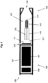
- FIG. 1 shows one example of a smoking system having a liquid storage portion.
- the smoking system 100 of Figure 1 is an electrically heated smoking system and comprises a housing 101 having a mouthpiece end 103 and a body end 105.
- an electric power supply in the form of battery 107 and electric circuitry in the form of circuitry 109 and a puff detection system 111.
- a liquid storage portion in the form of cartridge 113 containing liquid 115, a capillary wick 117 and a heating element in the form of heating coil 119.
- One end of the capillary wick 117 extends into the cartridge 113 and the other end of the capillary wick 117 is surrounded by the heating coil 119.
- the heating coil is connected to the electric circuitry via connections 121.
- the housing 101 also includes an air inlet 123, an air outlet 125 at the mouthpiece end and a chamber in the form of aerosol forming chamber 127.
- Liquid 115 is transferred by capillary action from the cartridge 113 from the end of the wick 117 which extends into the cartridge to the other end of the wick 117 which is surrounded by the heating coil.
- the puff detection system 111 senses the puff and activates the heating coil 119.
- the battery 107 supplies a pulse of energy to the heating coil 119 to heat the end of the wick 117 surrounded by the heating coil.
- the liquid in that end of the wick 117 is vaporized by the heating coil 119 to create a supersaturated vapour.
- the liquid being vaporized is replaced by further liquid moving along the wick 117 by capillary action. (This is sometimes referred to as "pumping action”.)
- the supersaturated vapour created is mixed with and carried in the air flow from the air inlet 123.
- the vapour condenses to form an inhalable aerosol, which is carried towards the outlet 125 and into the mouth of the user.
- the circuitry 109 and the puff detection system 111 are preferably programmable.
- the circuitry 109 and puff detection system 111 can be used to manage the device operation. This, in conjunction with the physical design of the electrically heated smoking system, can assist with control of the particle size in the aerosol.
- the capillary wick can be made from a variety of porous or capillary materials and preferably has a known, pre-defined capillarity. Examples include ceramic- or graphite-based materials in the form of fibres or sintered powders. Wicks of different porosities can be used to accommodate different liquid physical properties such as density, viscosity, surface tension and vapour pressure. The wick must be suitable so that the required amount of liquid can be delivered to the heating coil.
- Figure 1 shows one example of a smoking system which may be used with the present invention.
- the smoking system need not be electrically operated.
- additional air inlets may be provided, for example, spaced circumferentially around the housing.
- a puff detection system need not be provided.
- the system could operate by manual operation, for example, the user operating a switch when a puff is taken.
- the housing could comprise a separable shell and mouthpiece.
- the overall shape and size of the housing could be altered.
- the liquid cartridge may be omitted and the capillary wick could simply be pre-loaded with liquid before use.
- Other variations are, of course, possible.
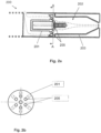
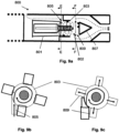
- Figures 2a (not according to the invention), and 2b (not according to the invention) show a first embodiment of the smoking system.
- Figure 2a shows a cross sectional view of the mouthpiece end of the first embodiment of the smoking system 200.
- the smoking system 200 includes guides for channelling the air flow within the smoking system.
- the guides are provided in removable insert 201 and in the housing inside walls 203. The air flow is shown by the dotted arrows.
- the removable insert 201 extends across the entire cross section of the smoking system 200 and includes channels 205 for channelling the air flow between the air inlet and the capillary wick and heating coil.
- the liquid cartridge, the capillary wick and the heating coil all form part of the removable insert 201, although this need not be the case.
- the channels 205 taper inward to direct the air flow generally in the direction of the longitudinal axis of the housing but diagonally towards the capillary wick and heating coil.
- the housing inside walls 203 are shaped to form the aerosol forming chamber 202 and provide guides for channelling the air and aerosol flow between the capillary wick and heating coil and the air outlet, through the aerosol forming chamber 202.
- the housing inside walls 203 are tapered towards the air outlet and thereby direct the air and aerosol flow substantially in the direction of the longitudinal axis of the housing.
- Figure 2b is a cross section along line A-A of Figure 2a.
- Figure 2b shows an alternative arrangement for the channels 205 in removable insert 201.
- the cross section of the device is shown as circular in Figures 2a, and 2b , this need not be the case.
- the inlet of each channel is circumferentially aligned with the outlet of the channel.
- the insert 201 comprises a locating pin or protrusion (not shown) on its outer surface for cooperating with a recess (also not shown) on the inside of the housing walls, so as to ensure that the insert is correctly positioned within the smoking system. This may be important for the electrical connections to the heating coil, for example.
- the embodiment shown in Figures 2a, and 2b provides a substantially axially directed incoming air flow from the air inlet to the capillary wick and heating coil and a substantially axially directed outgoing air flow from the capillary wick and heating coil to the air outlet. It has been found that managing the air flow in this way improves the aerosol formation occurring within the smoking system. The air flow management may also reduce condensation and hence leakage.
- the guides provided by insert 201 channel the air flow so as to concentrate air flow onto the wick and heating element and so as to increase turbulence. This decreases the particle size of the aerosol inhaled by a user.
- the guides provided by the housing inside walls 203 reduce the volume of the aerosol forming chamber 202 in the smoking system and therefore improve aerosol flow towards the air outlet. This improves the smoking experience.
- the guides upstream of the capillary wick and heating coil may be formed as one or more removable portions (insert 201, as shown) or alternatively as an integral part of the housing or as a combination of both.
- the guides downstream of the capillary wick and heating coil may be formed as one or more removable portions or alternatively as an integral part of the housing (shaped housing inside walls 203, as shown) or as a combination of both.
- Any number of channels 205 may be formed in the insert 201.
- the channels may be evenly or non-evenly distributed circumferentially around the insert.
- the channels may be arranged as several rows forming circles of different diameters.
- the channels may have a constant cross sectional shape and area along their length, or the cross sectional shape can vary along the length.
- the channels may include some channels having different cross sectional shapes and areas from others.
- the channels may be formed in the insert by machining. Alternatively, the insert may be formed together with the channels by injection moulding.
- the channels may be formed at any appropriate angle to the longitudinal axis of the housing.
- the housing inside walls 203 may be shaped appropriately for the desired volume and shape of the aerosol forming chamber 202 within the smoking system.
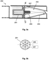
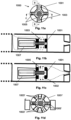
- Figures 3a and 3b show a second embodiment of the smoking system.
- Figure 3a shows a cross sectional view of the mouthpiece end of the second embodiment of the smoking system 250.
- the smoking system 250 includes guides for channelling the air flow within the smoking system.
- the guides are provided in removable insert 251 and in the housing inside walls 253. The air flow is shown by the dotted arrows.
- the removable insert 251 extends across the entire cross section of the smoking system 250 and includes primary channels 255 and secondary channels 257 for channelling the air flow between the air inlet and the capillary wick and heating coil.
- channels 255, 257 are substantially tubular bores in the insert 251.
- the liquid cartridge, the capillary wick and the heating coil all form part of the removable insert 251, although this need not be the case.
- the primary channels 255 in Figures 3a and 3b taper inward to direct the air flow generally in the direction of the longitudinal axis of the housing but diagonally towards the capillary wick and heating coil.
- the secondary channels 257 extend generally parallel to the longitudinal axis of the housing.
- the secondary channels 257 are closer to the outside of the smoking system. This creates a secondary air flow which substantially bypasses the wick. This secondary airflow therefore carries fewer aerosol droplets than the air flow which is closer to the wick.
- This secondary, relatively dry, airflow close to the inside walls may reduce the amount of condensation forming on the inside walls. This may reduce leakage.
- the housing inside walls 253 are shaped to form the aerosol forming chamber 252 and provide guides for channelling the air and aerosol flow between the capillary wick and heating coil and the air outlet, through the aerosol forming chamber 252.
- the housing inside walls 253 are tapered towards the air outlet and thereby direct the air and aerosol flow substantially in the direction of the longitudinal axis of the housing.
- Figure 3b is a cross section along line A"-A" of Figure 3a .
- the insert 251 comprises primary channels 255 and secondary channels 257.
- the inlet of each primary channel 255 is circumferentially aligned with the outlet of the channel, as in Figure 2a .
- the primary channels 255 may be twisted around the axis of the housing, as in Figure 2b .
- the secondary channels 257 extend in the direction of the longitudinal axis of the housing.
- one or more of the secondary channels 257 may be angled to the longitudinal axis of the housing.
- the secondary channels 257 are closer to the housing than primary channels 255. Thus, the air flow through secondary channels 257 is towards the outside of the air flow through primary channels 255.
- the inlet of each secondary channel 257 is circumferentially aligned with the outlet of the channel.
- the secondary channels 257 may alternatively be twisted around the axis of the housing.
- the insert 251 comprises a locating pin or protrusion (not shown) on its outer surface for cooperating with a recess (also not shown) on the inside of the housing walls, so as to ensure that the insert is correctly positioned within the smoking system. This may be important for the electrical connections to the heating coil, for example.
- the embodiment shown in Figures 3a and 3b provides a substantially axially directed incoming air flow from the air inlet to the capillary wick and heating coil and a substantially axially directed outgoing air flow from the capillary wick and heating coil to the air outlet.
- the embodiment shown in Figures 3a and 3b provides an additional substantially axially directed incoming air flow from the air inlet to the capillary wick and heating coil and an additional substantially axially directed outgoing air flow from the capillary wick and heating coil to the air outlet.
- the additional airflow is towards the outside of the smoking system. Because the additional air flow is less close to the heating coil, it tends to carry less aerosol. Thus, it may contribute to improved aerosol characteristics and reduced condensation.
- the guides provided by insert 251 channel the air flow so as to concentrate air flow onto the wick and heating element and so as to increase turbulence. This decreases the particle size of the aerosol inhaled by a user. They also provide an additional air flow which may reduce condensation forming in the smoking system.
- the guides provided by the housing inside walls 253 reduce the volume of the aerosol forming chamber 252 in the smoking system and therefore improve aerosol flow towards the air outlet. This improves the smoking experience.
- the guides upstream of the capillary wick and heating coil may be formed as one or more removable portions (insert 251, as shown) or alternatively as an integral part of the housing or as a combination of both.
- the guides downstream of the capillary wick and heating coil may be formed as one or more removable portions or alternatively as an integral part of the housing (shaped housing inside walls 253, as shown) or as a combination of both.
- Any number of channels 255, 257 may be formed in the insert 201.
- the channels may be evenly or non-evenly distributed circumferentially around the insert.
- the channels may be arranged as several rows forming circles of different diameters.
- the channels may have a constant cross sectional shape and area along their length, or the cross sectional shape can vary along the length.
- the channels may include some channels having different cross sectional shapes and areas from others.
- the channels may be formed in the insert by machining. Alternatively, the insert may be formed together with the channels by injection moulding.
- the channels may be formed at any appropriate angle to the longitudinal axis of the housing.
- the housing inside walls 253 may be shaped appropriately for the desired volume and shape of the aerosol forming chamber 252 within the smoking system.
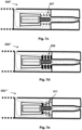
- Figures 4a and 4b show a third embodiment of the smoking system.
- Figure 4a shows a cross sectional view of the mouthpiece end of the second embodiment of the smoking system 300.
- the smoking system 300 includes guides for channelling the air flow within the smoking system.
- the guides are provided in removable insert 301 and in the housing inside walls 303. The air flow is shown by the dotted arrows.
- removable insert 301 extends across the entire cross section of the smoking system. However, in this embodiment, it also extends further upstream than the insert 201.
- the removable insert 301 includes channels 305 for channelling the air flow between the air inlet and the capillary wick and heating coil.
- the channels 305 extend in the direction of the longitudinal axis of the housing at their upstream end, then taper inward at their downstream end.
- the channels 305 direct the air flow generally in the direction of the longitudinal axis of the housing initially, then diagonally towards the capillary wick and heating coil.
- the liquid cartridge, the capillary wick and the heating coil all form part of the removable insert 301, although this need not be the case.
- the housing inside walls 303 are shaped to form the aerosol forming chamber 302 and to provide guides for channelling the air and aerosol flow between the capillary wick and heating coil and the air outlet, through the aerosol forming chamber 302.
- the housing inside walls 303 are tapered towards the air outlet and thereby direct the air and aerosol flow substantially in the direction of the longitudinal axis of the housing.
- Figure 4b is a cross section along line B-B of Figure 4a .
- the insert 301 comprises channels 305.
- Around the circumference of the insert 301 are several contact zones 307 for contacting with the inside of the housing. That is to say, the channels are formed by assembly of the insert in the housing.
- the insert 301 comprises a locating pin or protrusion (not shown) on its outer surface for cooperating with a recess (also not shown) on the inside of the housing walls, so as to ensure that the insert is correctly positioned within the smoking system. This may be important for the electrical connections to the heating coil, for example.
- the embodiment shown in Figures 4a and 4b provides a substantially axially directed incoming air flow from the air inlet to the capillary wick and heating coil and a substantially axially directed outgoing air flow from the capillary wick and heating coil to the air outlet. It has been found that managing the air flow in this way improves the aerosol formation occurring within the smoking system. The air flow management may also reduce condensation and hence leakage.
- the guides provided by insert 301 channel the air flow so as to concentrate air flow onto the wick and heating element and so as to increase turbulence. This decreases the particle size of the aerosol inhaled by a user.
- the guides provided by the housing inside walls 303 reduce the volume of the aerosol forming chamber 302 in the smoking system and therefore improve aerosol flow towards the air outlet. This improves the smoking experience.
- the guides upstream of the capillary wick and heating coil may be formed as one or more removable portions (insert 301, as shown) or alternatively as an integral part of the assembly or as a combination of both.
- the guides downstream of the capillary wick and heating coil may be formed as one or more removable portions or alternatively as an integral part of the assembly (shaped housing inside walls 303, as shown) or as a combination of both.
- Any number of channels 305 may be formed in the insert 301.
- the channels may be evenly or non-evenly distributed circumferentially around the insert.
- the channels may be arranged as several rows forming circles of different diameters.
- the channels may have a constant cross sectional shape and area along their length, or the cross sectional shape can vary along the length.
- the channels may include some channels having different cross sectional shapes and areas from others.
- the channels may be formed in the insert by machining. Alternatively, the insert may be formed together with the channels by injection moulding.
- the channels may be formed at any appropriate angle to the longitudinal axis of the housing.
- the housing inside walls 303 may be shaped appropriately for the desired volume and shape of the aerosol forming chamber 302 within the smoking system.
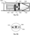
- Figure 5 shows a fourth embodiment of the smoking system.
- Figure 5 shows a cross sectional view of the mouthpiece end of the third embodiment of the smoking system 400.
- the smoking system 400 includes guides for channelling the air flow within the smoking system.
- the guides are provided by removable insert 401, by the housing inside walls 403 and by impactor 405. The air flow is shown by the dotted arrows.
- the removable insert 401 is similar to removable insert 301 shown in Figures 4a and 4b . and extends across the entire cross section of the smoking system 400.
- the removable insert 401 includes channels 407 for channelling the air flow between the air inlet and the capillary wick and heating coil.
- the channels 407 extend in the direction of the longitudinal axis of the housing at their upstream end, then taper inward at their downstream end.
- the channels 407 direct the air flow generally in the direction of the longitudinal axis of the housing initially, then diagonally towards the capillary wick and heating coil.
- the liquid cartridge, the capillary wick and the heating coil all form part of the removable insert 401, although this need not be the case.
- the insert 401 comprises a locating pin or protrusion (not shown) on its outer surface for cooperating with a recess (also not shown) on the inside of the housing walls, so as to ensure that the insert is correctly positioned within the smoking system.
- a locating pin or protrusion (not shown) on its outer surface for cooperating with a recess (also not shown) on the inside of the housing walls, so as to ensure that the insert is correctly positioned within the smoking system.
- This may be important for the electrical connections to the heating coil, for example.
- the insert could alternatively take the form shown in Figure 2a or another suitable form.
- the housing inside walls 403 and impactor 405 provide guides for channelling the aerosol flow between the capillary wick and heating coil and the air outlet.
- the housing inside walls 403 and impactor 405 also form the aerosol forming chamber 402.
- the housing inside walls are shaped so as to direct the flow away from the heating coil in the radial direction, that is to say, substantially perpendicular to the longitudinal axis of the housing.
- the impactor 405 comprises a removable insert which may be positioned in the centre of the device, supported by the housing walls (see dotted lines).
- the impactor 405 allows larger aerosol particles to be trapped on its upstream side. This produces a filtering effect and reduces the average particle size. This is shown schematically in Figure 5 .
- the housing inside walls 403 and impactor 405 direct the air flow towards the air outlet.
- the embodiment shown in Figure 5 provides a substantially axially directed incoming air flow from the air inlet to the capillary wick and heating coil and a substantially radially directed air flow downstream of the capillary wick and heating coil. It has been found that managing air flow in this way improves the aerosol formation occurring within the smoking system.
- the air flow management may also reduce condensation and hence leakage.
- the guides provided by insert 401 channel the air flow so as to concentrate air flow onto the wick and heating element and so as to increase turbulence. This decreases the particle size of the aerosol inhaled by a user.
- the guides provided by the housing inside walls 403 and impactor allow larger aerosol particles to be trapped and prevented from exiting through the air outlet.
- the arrangement allows the capillary wick and heating coil to be supplied with cool, non-saturated air, in order to decrease the aerosol particle size. This improves the smoking experience.
- the guides upstream of the capillary wick and heating coil may be formed as one or more removable portions (insert 401, as shown) or alternatively as an integral part of the housing or as a combination of both.
- the guides downstream of the capillary wick and heating coil may be formed as one or more removable portions or alternatively as an integral part of the housing or as a combination of both (shaped housing inside walls 403 combined with removable impactor 405, as shown). Any number of channels 407 may be formed in the insert 401.
- the channels may be evenly or non-evenly distributed circumferentially around the insert.
- the channels may be arranged as several rows forming circles of different diameters.
- the channels may have a constant cross sectional shape and area along their length, or the cross sectional shape can vary along the length.
- the channels may include some channels having different cross sectional shapes and areas from others.
- the channels may be formed in the insert by machining. Alternatively, the insert may be formed with the channels by injection moulding.
- the channels may be formed at any appropriate angle to the longitudinal axis of the housing.
- the housing inside walls 403 and impactor 405 may be shaped and sized appropriately for the desired volume and shape of the aerosol forming chamber 402 within the smoking system.
- the impactor 405 may be formed with any appropriate shape and is preferably designed in conjunction with the shaped housing inside walls 403, in order to channel the air and aerosol flow as desired.
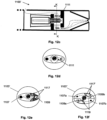
- Figures 6a (not according to the invention) and 6b (not according to the invention) show a fifth embodiment of the smoking system.
- Figure 6a shows a cross sectional view of the mouthpiece end of the fourth embodiment of the smoking system 500.
- the smoking system 500 includes guides for channelling the air flow within the smoking system.
- the guides are provided by removable insert 501, by the housing inside walls 503 and by impactor 505.
- the removable insert 501 is similar to removable insert 201 shown in Figures 2a, and 2b and extends across the entire cross section of the smoking system 500 and includes channels 507 for channelling the air flow between the air inlet and the capillary wick and heating coil.
- the liquid cartridge, the capillary wick and heating coil all form part of the removable insert 501, although this need not be the case.
- the channels 507 taper inward to direct the air flow generally in the direction of the longitudinal axis of the housing but diagonally towards the capillary wick and heating coil.
- the insert 501 comprises a locating pin or protrusion (not shown) on its outer surface for cooperating with a recess (also not shown) on the inside of the housing walls, so as to ensure that the insert is correctly positioned within the smoking system.
- a locating pin or protrusion (not shown) on its outer surface for cooperating with a recess (also not shown) on the inside of the housing walls, so as to ensure that the insert is correctly positioned within the smoking system.
- This may be important for the electrical connections to the heating coil, for example.
- the insert could alternatively take the form shown in Figures 4a and 5 or another suitable form.
- housing inside walls 503 are tapered inward to form the aerosol forming chamber 502.
- the housing inside walls 503 together with the impactor 505 provide guides for channelling the aerosol flow between the capillary wick and heating coil and the air outlet.
- the housing inside walls 503 are shaped so as to form a nozzle to direct and accelerate the air flow substantially in the axial direction.
- Impactor 505 is located directly downstream of the aerosol forming chamber.
- Figure 6b is a cross section along line C-C of Figure 6a .
- the impactor 505 acts to trap larger aerosol particles and therefore provide a filtering effect.
- the impactor 505 comprises a plate 505a which may be positioned in the centre of the housing, supported at the housing walls by struts 505b.
- the plate 505a acts to trap the larger aerosol particles exiting the aerosol forming chamber 502.
- the embodiment shown in Figures 6a and 6b provides an accelerated, substantially axially directed air flow downstream of the capillary wick and heating coil. It has been found that managing the air flow in this way improves the aerosol formation occurring within the smoking system.
- the air flow management may also reduce condensation and hence leakage.
- the guides provided by insert 501 channel the air flow so as to concentrate air flow onto the wick and heating element and so as to increase turbulence. This decreases the particle size of the aerosol inhaled by a user.
- the tapered nozzle shape provided by the housing inside walls 503 accelerate the aerosol downstream towards the impactor 505 and the plate 505a of the impactor 505 traps larger aerosol particles to prevent them exiting through the air outlet.
- the arrangement allows the capillary wick and heating coil to be supplied with cool, non-saturated air, in order to decrease the aerosol particle size. It also allows any larger aerosol particles that do form to be filtered out of the flow. This improves the smoking experience.
- the guides upstream of the capillary wick and heating coil may be formed as one or more removable portions (insert 501, as shown) or alternatively as an integral part of the housing or as a combination of both.
- the guides downstream of the capillary wick and heating coil may be formed as one or more removable portions or alternatively as an integral part of the housing or as a combination of both (shaped housing inside walls 503 combined with removable impactor 505, as shown). Any number of channels 507 may be formed in the insert 501.
- the channels may be evenly or non-evenly distributed circumferentially around the insert.
- the channels may be arranged as several rows forming circles of different diameters.
- the channels may have a constant cross sectional shape and area along their length, or the cross sectional shape can vary along the length.
- the channels may include some channels having different cross sectional shapes and areas from others.
- the channels 507 may be twisted around the axis of the housing to provide a swirled air flow.
- the channels may be formed in the insert by machining. Alternatively, the insert may be formed together with the channels by injection moulding.
- the channels may be formed at any appropriate angle to the longitudinal axis of the housing.
- the housing inside walls 503 may be shaped appropriately for the desired volume and shape of the aerosol forming chamber 502 within the smoking system and for the desired acceleration of the aerosol towards the impactor 505.
- the impactor may be formed by machining or injection moulding.
- the shape and size of the impactor plate 505a may be varied.
- the distance between the downstream end of the aerosol forming chamber 502 and the impactor plate may be varied.
- Figures 7a to 7e show a sixth embodiment of the smoking system according to the invention.
- Figures 7a to 7e each show a cross sectional view of the mouthpiece end of the fifth embodiment of the smoking system.
- the smoking system includes guides for channelling the air flow within the smoking system. The air flow is shown by the dotted arrows.
- Figure 7a shows a first arrangement of the smoking system 600.
- the guides are provided by removable insert 601 and by the housing inside walls 603.
- the removable insert 601 extends only across the centre of the smoking system 600, thereby directing the air flow between the air inlet and the capillary wick and heating coil to the outer circumference of the device.
- the removable insert 601 is shaped so that, at the capillary wick and heating coil, the air flow is directed onto the capillary wick and heating coil in a substantially radial direction, that is to say, substantially perpendicular to the longitudinal axis of the housing.
- the liquid cartridge, the capillary wick and the heating coil all form part of the removable insert 601, although this need not be the case.
- housing inside walls 603 provide guides for channelling the air and aerosol flow between the capillary wick and heating coil and the air outlet.
- the housing inside walls 603 also define the aerosol forming chamber 602.
- the housing inside walls 603 are shaped so as to direct the air and aerosol flow substantially in the direction of the longitudinal axis of the housing.
- Figure 7b shows a second arrangement of the smoking system 600'.
- the arrangement shown in Figure 7b is identical to that shown in Figure 7a except that an additional insert 605 is provided in the smoking system 600' of Figure 7b .
- the additional insert 605 provides additional guides for directing air flow.
- the insert 605 is a ribbed insert surrounding the capillary wick and heating coil. It is shaped so as to direct the air flow onto the capillary wick and heating coil in a substantially radial direction, that is to say, substantially perpendicular to the longitudinal axis of the housing.
- Figure 7c shows a third arrangement of the smoking system 600".
- the arrangement shown in Figure 7c is identical to that shown in Figure 7a except that an additional insert 607 is provided in the smoking system 600" of Figure 7c .
- the additional insert 607 provides additional guides for directing air flow.
- the insert 607 is a grill insert comprising a tube having a number of longitudinally spaced holes.
- the insert 607 surrounds the capillary wick and heating coil and directs the air flow through the holes in the grill and onto the capillary wick and heating coil in a substantially radial direction, that is to say, substantially perpendicular to the longitudinal axis of the housing.
- Figure 7d shows a fourth arrangement of the smoking system 600"'.
- the arrangement shown in Figure 7d is identical to that shown in Figure 7a except that an additional insert 609 is provided in the smoking system 600"' of Figure 7d .
- the additional insert 609 provides additional guides for directing air flow.
- the insert 609 is a grooved insert comprising a solid cylindrical tube having a number of channels formed in the radial direction.
- the insert 609 surrounds the capillary wick and heating coil and directs the air flow through the radial channels and onto the capillary wick and heating coil in a substantially radial direction, that is to say, substantially perpendicular to the longitudinal axis of the housing.
- Figure 7e shows a fifth arrangement of the smoking system 600"".
- the arrangement shown in Figure 7e is identical to that shown in Figure 7a except that an additional insert 611 is provided in the smoking system 600"" of Figure 7e .
- the additional insert 611 provides additional guides for directing air flow.
- the insert 611 is a grooved insert comprising a solid conical tube having a number of channels formed in the radial direction.
- the insert 611 surrounds the capillary wick and heating coil and directs the air flow through the radial channels and onto the capillary wick and heating coil in a substantially radial direction, that is to say, substantially perpendicular to the longitudinal axis of the housing.
- the embodiments shown in Figure 7a to 7e provide a substantially radially directed air flow onto the capillary wick and heating coil and a substantially axially directed air and aerosol flow downstream of the capillary wick and heating coil. It has been found that managing air flow in this way improves the aerosol formation occurring within the smoking system. The air flow management may also reduce condensation and hence leakage.
- the guides provided by the insert 601, and the additional insert 605, 607, 609, 611 if present, channel the air flow as to direct the air flow onto the capillary wick and heating coil in a substantially radial direction. This provides the capillary wick and heating coil with cool, non-saturated air, which decreases the particle size of the aerosol inhaled by a user.
- the guides provided by the housing inside walls 603 reduce the volume of the cavity in the smoking system and therefore improve aerosol flow towards the air outlet. This improves the smoking experience.
- the guides upstream of the capillary wick and heating coil may be formed as one or more removable portions (inserts 601, 605, 607, 609 and 611, as shown) or alternatively as an integral part of the housing or as a combination of both.
- the guides downstream of the capillary wick and heating coil may be formed as one or more removable portions or alternatively as an integral part of the housing (shaped housing inside walls 603, as shown) or as a combination of both.
- the insert 601 is shown without channels, although longitudinal channels towards the outside of the insert may be provided. In addition, if channels are provided, the insert may extend across the entire cross section of the housing. Any configuration of channels may be provided. The channels may be twisted around the axis of the housing, so as to encourage a swirled airflow.
- the channels in inserts 601, 605, 609, 611 and the holes in insert 607 may be formed by machining. Alternatively, the insert may be formed with channels or holes already formed, by injection moulding. Any number of holes or channels may be formed in inserts 605, 607, 609, 611.
- the insert 601 comprises a locating pin or protrusion (not shown) on its outer surface for cooperating with a recess (also not shown) on the inside of the housing walls, so as to ensure that the insert is correctly positioned within the smoking system.
- a locating pin or protrusion (not shown) on its outer surface for cooperating with a recess (also not shown) on the inside of the housing walls, so as to ensure that the insert is correctly positioned within the smoking system.
- the inserts 605, 607, 609, 611 may also be provided with such a locating pin or protrusion.
- the housing inside walls 603 may be shaped appropriately for the desired volume and shape of the aerosol forming chamber within the smoking system.
- Figures 8a to 8c show a seventh embodiment of the smoking system according to the invention.
- Figure 8a shows a cross sectional view of the mouthpiece end of the sixth embodiment of the smoking system 700.
- the smoking system 700 includes guides for channelling the air flow within the smoking system.
- the guides are provided by removable insert 701 and by the housing walls 703. The air flow is shown by the dotted arrows.
- the removable insert 701 is similar to removable insert 601 shown in Figures 7a to 7e and extends only across the centre of the smoking system 700, thereby directing the air flow between the air inlet and the capillary wick and heating coil to the outer circumference of the device.
- the liquid cartridge, the capillary wick and the heating coil all form part of the removable insert 701, although this need not be the case.
- housing inside walls 703 provide guides for channelling the aerosol flow onto the capillary wick and heating coil, and between the capillary wick and heating coil and the air outlet.
- the housing inside walls 703 also define the aerosol forming chamber 702.
- the housing walls 703 are shaped so that the incoming air flow onto the capillary wick and heating coil is directed in an upstream channel 705 tangential to the circular cross section of the device and the circular cross section of the aerosol forming chamber 702.
- Figure 8b is a cross section along line D-D of Figure 8a .
- the housing inside walls 703 are shaped so that the channel 705 provides an air flow towards the capillary wick and heating coil that is in the tangential direction. This produces a spiralling air flow around the capillary wick and heating coil towards the air outlet.
- Figure 8c is a cross section also along line D-D showing an alternative arrangement, in which two channels 705, 705' towards the capillary wick and heating coil are provided. Both channels direct the air flow in a tangential direction and together they produce a spiralling air flow around the capillary wick and heating coil towards the air outlet. Additional tangential upstream channels could also be provided.
- the embodiment shown in Figures 8a, 8b and 8c provides a substantially tangentially directed air flow onto the capillary wick and heating coil and a substantially spiralling air flow around the capillary wick and heating coil and from the capillary wick and heating coil to the air outlet. It has been found that managing the air flow in this way improves the aerosol formation occurring within the smoking system. The air flow management may also reduce condensation and hence leakage.
- the shaped inside walls 703 of the housing, together with the insert 701 direct the air flow so as to supply cool and non-saturated air to the capillary wick and heating coil. Once air flow targets the capillary wick and heating coil, it is immediately evacuated towards the air outlet. This decreases the particle size of the aerosol inhaled by a user.
- the spiralling air flow around the capillary wick and heating coil increases turbulence and reduces aerosol particle size.
- the size of the tangential channel or channels and its position relative to the longitudinal axis of the device influence the air flow around the capillary wick and heating coil and therefore the aerosol characteristics.
- the centrifugal forces in the spiralling air flow may allow larger aerosol particles to impact and be trapped on the outer walls of the aerosol forming chamber 702. This is shown schematically in Figure 8a .
- the arrangement of Figure 8c further improves aerosol formation by providing a better flow distribution within the aerosol forming chamber.
- the cross section of the device is preferably circular, so that the channel 705 can define a tangential air flow.
- Other cross sectional shapes are also possible, as long as some sort of upstream tangential channel can be defined.
- More than one air inlet (in the housing) may be provided.
- the guides upstream of the capillary wick and heating coil may be formed as one or more removable portions or alternatively as an integral part of the housing or as a combination of both (removable insert 701 combined with shaped housing walls 703, as shown).
- the guides downstream of the capillary wick and heating coil may be formed as one or more removable portions or alternatively as an integral part of the housing (shaped housing inside walls 703, as shown) or as a combination of both.
- the insert 701 is shown without channels, although longitudinal channels towards the outside of the insert 701 may be provided. In addition, if channels are provided, the insert may extend across the entire cross section of the housing. Any configuration of channels may be provided. The channels may be twisted around the axis of the housing, so as to encourage a swirled airflow. Any channels in insert 701 may be formed by machining. Alternatively, the insert may be formed with channels or holes already formed, by injection moulding.
- the insert 701 may comprise a locating pin or protrusion (not shown) on its outer surface for cooperating with a recess (also not shown) on the inside of the housing walls, so as to ensure that the insert is correctly positioned within the smoking system. This may be important for the electrical connections to the heating coil, for example.
- the housing inside walls 703 may be shaped appropriately for the desired volume and shape of the aerosol forming chamber within the smoking system. This affects the spiralling aerosol flow around the capillary wick and heating coil and therefore the aerosol characteristics.
- the tangential channels 705, 705' may be positioned at any height along the capillary wick and may have any suitable cross section.
- Figures 9a to 9c show an eighth embodiment of the smoking system according to the invention.
- Figure 9a shows a cross sectional view of the mouthpiece end of the seventh embodiment of the smoking system 800.
- the smoking system 800 includes guides for channelling the air flow within the smoking system.
- the guides are provided by removable insert 801, in the shaped housing walls 803 and by impactor 807. The air flow is shown by the dotted arrows.
- the removable insert 801 is similar to removable insert 601 shown in Figures 7a to 7e and removable insert 701 shown in Figure 8a and extends only across the centre of the smoking system 800, thereby directing the air flow between the air inlet and the capillary wick and heating coil to the outer circumference of the device.
- the liquid cartridge, the capillary wick and the heating coil all form part of the removable insert 801, although this need not be the case.
- housing inside walls 803 provide guides for channelling the air flow onto the capillary wick and heating coil.
- the housing walls 803 are shaped so that the incoming air flow onto the capillary wick and heating coil is directed through an upstream channel 805 tangential to the circular cross section of the device and the circular cross section of the aerosol forming chamber 802.
- an impactor 807 is provided at the downstream end of the capillary wick and heating coil.
- the impactor provides guides for channelling the air flow away from the capillary wick and heating coil and towards the air outlet.
- the impactor 807 in conjunction with the housing inside walls, also defines the aerosol forming chamber 802.
- the air flow is directed away from the capillary wick and heating coil in the radial direction in downstream channels 809, that is to say, substantially perpendicular to the longitudinal axis of the housing.
- the impactor 807 allows larger aerosol particles to be trapped on its upstream side. This is shown schematically in Figure 9a .
- the housing inside walls 803 may be tapered to direct the air flow towards the air outlet, although this is not shown in Figure 9a .
- Figure 9b is a cross section along line E-E of Figure 9a showing the upstream channel 805.
- the housing walls 803 are shaped so that the channel 805 provides an air flow towards the capillary wick and heating coil that is in the tangential direction. This produces a spiralling air flow around the capillary wick and heating coil.
- Figure 9c is a cross section along line F-F of Figure 9a showing the downstream channels 809.
- the impactor 807 and housing walls 803 cooperate so that the channels 809 provide an air flow away from the capillary wick and heating coil that is in substantially the radial direction. That is to say, downstream of the spiralling air flow around the capillary wick and heating coil, the aerosol flow is directed in the radial direction and then towards the air outlet.
- FIGS. 9a, 9b and 9c provides a substantially tangentially directed air flow onto the capillary wick and heating coil, a substantially spiralling air flow around the capillary wick and heating coil and a substantially radially directed air flow away from the capillary wick and heating coil to the air outlet. It has been found that managing the air flow in this way improves the aerosol formation occurring within the smoking system. The air flow management may also reduce condensation and hence leakage.
- the shaped inside walls 803 of the housing, together with the insert 801 direct the air flow so as to supply cool and non-saturated air to the capillary wick and heating coil. This decreases the particle size of the aerosol inhaled by a user.
- the spiralling air flow around the capillary wick and heating coil increases turbulence and reduces aerosol particle size. Larger aerosol particles may also become trapped on the inside walls of the aerosol forming chamber 802 due to centrifugal forces.
- the radially directed outgoing air flow means that once air flow targets the capillary wick and heating coil, it is immediately evacuated towards the air outlet. Additional upstream tangential channels may be provided (as in Figure 8c for example) which may provide a better flow distribution within the aerosol forming chamber.
- the size of the tangential channel or channels and its position relative to the longitudinal axis of the device influence the air flow around the capillary wick and heating coil and therefore the aerosol characteristics.
- the impactor may allow larger aerosol particles to impact on its upstream wall. This is shown schematically in Figure 9a .
- the cross section of the device is preferably circular, so that the channel 805 can define a tangential air flow.
- Other cross sectional shapes are also possible, as long as an upstream tangential channel can be defined.
- More than one air inlet (in the housing) may be provided.
- the guides upstream of the capillary wick and heating coil may be formed as one or more removable portions or alternatively as an integral part of the housing or as a combination of both (removable insert 801 combined with shaped housing walls 803, as shown).
- the guides downstream of the capillary wick and heating coil may be formed as one or more removable portions or alternatively as an integral part of the housing or as a combination of both (shaped housing inside walls 803 combined with impactor 807, as shown).
- the insert 801 is shown without channels, although longitudinal channels towards the outside of the insert 801 may be provided. In addition, if channels are provided, the insert may extend across the entire cross section of the housing. Any configuration of channels may be provided. The channels may be twisted around the axis of the housing, so as to encourage a swirled airflow. Any channels in insert 801 may be formed by machining. Alternatively, the insert may be formed with channels or holes already formed, by injection moulding.
- the insert 801 may comprise a locating pin or protrusion (not shown) on its outer surface for cooperating with a recess (also not shown) on the inside of the housing walls, so as to ensure that the insert is correctly positioned within the smoking system. This is important for the electrical connections to the heating coil, for example.
- the housing inside walls 803 may be shaped appropriately for the desired volume and shape of the aerosol forming chamber within the smoking system. This affects the spiralling aerosol flow around the capillary wick and heating coil and therefore the aerosol characteristics.
- the tangential channel 805 may be positioned at any height along the capillary wick and may have any suitable cross section. Any number of radial channels 809 may be provided.
- the impactor 807 may be formed with any appropriate shape and is preferably designed in conjunction with the shaped housing inside walls 803, in order to channel the air flow as desired.
- Figures 10a to 10d show a ninth embodiment of the smoking system according to the invention.
- Figure 10a shows a cross sectional view of the mouthpiece end of the eighth embodiment of the smoking system 900.
- the smoking system 900 includes guides for channelling the air flow within the smoking system.
- the guides are provided in removable insert 901 and in the shaped housing walls 903. The air flow is shown by the dotted arrows.
- the removable insert 901 is similar to removable inserts 601, 701 and 801 and extends only across the centre of the smoking system 900, thereby directing the air flow between the air inlet and the capillary wick and heating coil to the outer circumference of the housing.
- the liquid cartridge, the capillary wick and the heating coil all form part of the removable insert 901, although this need not be the case.
- the housing inside walls 903 provide guides for channelling the aerosol flow onto the capillary wick and heating coil and off the capillary wick and heating coil.
- the housing walls 903 are shaped so that the incoming air flow onto the capillary wick and heating coil is directed through an upstream channel 905 tangential to the circular cross section of the housing and the circular cross section of the aerosol forming chamber 902.
- the housing walls 903 are shaped so that the outgoing air flow off the capillary wick and heating coil is directed through an downstream channel 907 also tangential to the circular cross section of the housing and the circular cross section of the aerosol forming chamber 902.
- housing walls 903 are shaped to provide an impactor surface 909 downstream of the capillary wick and heating coil.
- the surface 909 may allow larger aerosol particles to be trapped. This is shown schematically in Figure 10a .
- the housing inside walls also define the aerosol forming chamber 902.
- the housing inside walls 903 may be tapered to direct the air flow towards the air outlet, although this is not shown in Figure 10a .
- Figure 10b is a cross section along line G-G of Figure 10a showing the upstream channel 905.
- the housing walls 903 are shaped so that the channel 905 provides an air flow towards the capillary wick and heating coil that is in the tangential direction. This produces a spiralling air flow around the capillary wick and heating coil.
- Figure 10c is a cross section along line H-H of Figure 10a showing the downstream channel 907.
- the housing walls 903 are shaped so that the channel 907 provides an air flow away from the capillary wick and heating coil that is in the tangential direction. That is to say, after the air has spiralled around the capillary wick and heating coil, it is directed in the tangential direction and then towards the air outlet.
- Figure 10d shows an alternative cross section along line H-H of Figure 10a , also showing downstream channel 907'.
- the channel 907 is on the same side of the device as the channel 905.
- the channel 907' is on the opposite side of the device as the channel 905.
- FIGS. 10a, 10b, 10c and 10d provides a substantially tangentially directed air flow onto the capillary wick and heating coil, a substantially spiralling air flow around the capillary wick and heating coil and a substantially tangentially directed air flow off the capillary wick and heating coil and then to the air outlet. It has been found that managing the air flow in this way improves the aerosol formation occurring within the smoking system. The air flow management may also reduce condensation and hence leakage.
- the shaped inside walls 903 of the housing, together with the insert 901 direct the air flow so as to supply cool and non-saturated air to the capillary wick and heating coil. This decreases the particle size of the aerosol inhaled by a user.
- the spiralling air flow around the capillary wick and heating coil increases turbulence and reduces aerosol particle size. Larger aerosol particles may also become trapped on the inside walls of the aerosol forming chamber 902 due to centrifugal forces.
- This is shown schematically in Figure 10a .
- the tangentially directed outgoing air flow means that once air flow has circled the capillary wick and heating coil, it is immediately evacuated towards the air outlet. Additional upstream or downstream tangential channels may be provided which may provide a better flow distribution within the aerosol forming chamber.
- the size of the tangential channels and their position relative to the longitudinal axis of the device influence the air flow around the capillary wick and heating coil and therefore the aerosol characteristics.
- the cross section of the device is preferably circular, so that the channels 905 and 907 can define a tangential air flow. However, other cross sectional shapes are also possible as long as tangential channels can be defined. More than one air inlet (in the housing) may be provided.
- the guides upstream of the capillary wick and heating coil may be formed as one or more removable portions or alternatively as an integral part of the housing or as a combination of both (removable insert 901 combined with shaped housing walls 903, as shown).
- the guides downstream of the capillary wick and heating coil may be formed as one or more removable portions or alternatively as an integral part of the housing (shaped housing walls 903, as shown) or as a combination of both.
- the insert 901 is shown without channels, although longitudinal channels towards the outside of the insert 901 may be provided. In addition, if channels are provided, the insert may extend across the entire cross section of the housing. Any configuration of channels may be provided. The channels may be twisted around the axis of the housing, so as to encourage a swirled air flow. Any channels in insert 901 may be formed by machining. Alternatively, the insert may be formed with channels or holes already formed, by injection moulding.
- the insert 901 may comprise a locating pin or protrusion (not shown) on its outer surface for cooperating with a recess (also not shown) on the inside of the housing walls, so as to ensure that the insert is correctly positioned within the smoking system. This is important for the electrical connections to the heating coil, for example.
- the housing inside walls 903 may be shaped appropriately for the desired volume and shape of the aerosol forming chamber within the smoking system. This affects the spiralling aerosol flow around the capillary wick and heating coil and therefore the aerosol characteristics.
- the tangential channels 905, 907 may be positioned at any height along the capillary wick and may have any suitable cross section. Any number of tangential upstream and downstream channels may be provided.
- Figures 11a to 11d show a tenth embodiment of the smoking system according to the invention.
- Figure 11a shows a cross sectional view of the smoking system including removable insert 1001.
- Figure 11b is a cross section along line B-B of Figure 11a , showing the mouthpiece end only.
- Figure 11c is a cross section along line C-C of Figure 11a , showing the mouthpiece end only.
- the smoking system 1000 includes guides for channelling the air flow within the smoking system. The air flow is shown by the dotted arrows.
- the removable insert 1001 is shown in cross section in Figure 11a .
- the insert includes upstream channels 1003 for channelling the air flow from the air inlet onto the capillary wick and heating coil and downstream channels 1005 for channelling the air flow away from the capillary wick and heating coil towards the air outlet.
- the channels 1003 and 1005 are substantially perpendicular to one another and also substantially perpendicular to the longitudinal axis of the housing.
- Figure 11b shows a cross section along B-B of Figure 11a
- Figure 11c shows a cross section along C-C of Figure 11a
- the guides are provided by removable insert 1001 and removable insert 1007.
- the removable insert 1007 is similar to removable inserts 601, 701, 801 and 901 and extends only across the centre of the smoking system 1000, thereby directing the air flow between the air inlet and the capillary wick and heating coil to the outer circumference of the housing.
- the liquid cartridge, the capillary wick and the heating coil all form part of the removable insert 1007, although this need not be the case.
- the removable insert 1001 is positioned around the capillary wick and heating coil. The removable insert 1001 extends across the entire cross section of the device.
- Figure 11b shows a cross section along B-B of Figure 11a
- Figure 11b shows the air flow upstream of the capillary wick and heating coil.
- the channels 1003 direct the air flow onto the capillary wick and heating coil in a substantially radial direction, that is to say, substantially perpendicular to the longitudinal axis of the housing.
- Figure 11c shows a cross section along C-C of Figure 11a
- Figure 11c shows the air flow downstream of the capillary wick and heating coil.
- the channels 1005 direct the air flow away from the capillary wick and heating coil in a substantially radial direction.
- the channels 1005 define the aerosol forming chamber 1002.
- the housing walls may additionally be tapered towards the air outlet, although this is not shown in Figures 11b and 11c .
- Figure 11d shows an alternative arrangement for the removable insert 1001'.
- the insert includes four upstream channels 1003' for channelling the air flow from the air inlet onto the capillary wick and heating coil.
- the insert also includes two downstream channels 1005' for channelling the air flow away from the capillary wick and heating coil towards the air outlet.
- the channels 1003' and 1005' are substantially perpendicular to the longitudinal axis of the housing.
- the channels are directed in the radial direction.
- two upstream channels 1003 are shown in Figure 11 a and four upstream channels 1003' are shown in Figure 11d
- any suitable number of upstream channels may be provided, all in the radial direction and substantially perpendicular to the longitudinal axis of the housing.
- two downstream channels 1005, 1005' are shown in Figures 11a and 11d
- any suitable number of downstream channels may be provided, all in the radial direction and substantially perpendicular to the longitudinal axis of the housing.
- the embodiments shown in Figures 11a to 11d provide a substantially radially directed air flow onto the capillary wick and heating coil and a substantially radially directed air flow off the capillary wick and heating coil. It has been found that managing air flow in this way improves the aerosol formation occurring within the smoking system. The air flow management may also reduce condensation and hence leakage.
- the guides provided by the inserts 1007 and 1001 channel the air flow as to direct the air flow onto the capillary wick and heating coil in a substantially radial direction. This provides the capillary wick and heating coil with cool, non-saturated air, which decreases the particle size of the aerosol inhaled by a user.
- the guides provided by the insert 1001 channel the air flow as to direct the air flow off the capillary wick and heating coil in a substantially radial direction and also reduce the volume of the aerosol forming chamber 1002 in the smoking system. This improves aerosol flow towards the air outlet. This improves the smoking experience.
- the guides upstream of the capillary wick and heating coil may be formed as one or more removable portions (inserts 1001 and 1007, as shown) or alternatively as an integral part of the housing or as a combination of both.
- the guides downstream of the capillary wick and heating coil may be formed as one or more removable portions (insert 1001, as shown) or alternatively as an integral part of the housing or as a combination of both.
- the insert 1007 is shown without channels, although longitudinal channels towards the outside of the insert may be provided. In addition, if channels are provided, the insert may extend across the entire cross section of the housing. Any configuration of channels may be provided. The channels may be twisted around the axis of the housing, so as to encourage a swirled air flow.
- the channels in insert 1007 may be formed by machining. Alternatively, the insert may be formed with channels or holes already formed, by injection moulding.
- the insert 1007 comprises a locating pin or protrusion (not shown) on its outer surface for cooperating with a recess (also not shown) on the inside of the housing walls, so as to ensure that the insert is correctly positioned within the smoking system. This is important for the electrical connections to the heating coil, for example.
- the channels may be evenly or non-evenly distributed circumferentially around the insert.
- the channels may have a constant cross sectional shape and area along their length, or the cross sectional shape can vary along the length.
- the channels may include some channels having different cross sectional shapes and areas from others.
- the channels in insert 1001 may be formed by machining.
- the insert may be formed with channels or holes already formed, by injection moulding.
- the insert 1001 comprises a locating pin or protrusion (not shown) on its outer surface for cooperating with a recess (also not shown) on the inside of the housing walls, so as to ensure that the insert is correctly positioned within the smoking system. This is important for the electrical connections to the heating coil, for example.
- the channels 1005 may be shaped appropriately for the desired volume and shape of the aerosol forming chamber within the smoking system.
- Figures 12a to 12n show an eleventh embodiment of the smoking system according to the invention.
- the smoking system includes guides for channelling the air flow within the smoking system. The air flow is shown by the dotted arrows.
- Figure 12a shows a first arrangement of the smoking system 1100
- Figure 12b is a cross section along line J-J of Figure 12a
- the guides are provided by removable insert 1101, second removable insert 1103 and by the shaped housing inside walls 1105.
- the removable insert 1101 extends only across the centre of the smoking system 1100, thereby directing the air flow between the air inlet and the capillary wick and heating coil to the outer circumference of the housing.
- the liquid cartridge, the capillary wick and the heating coil all form part of the removable insert 1101, although this need not be the case.
- the second removable insert 1103 is shaped so that the air flow is directed across the capillary wick and heating coil in a substantially perpendicular direction. That is to say, the air flow is substantially perpendicular to the longitudinal axis of the housing and to the capillary wick.
- the second removable insert 1103 provides an upstream channel 1107 on one side of the insert and a downstream channel 1109 on the other side of the insert. When the insert is positioned around the capillary wick and heating coil, the air therefore flows directly across the capillary wick and heating coil.
- the insert 1103 also defines the aerosol forming chamber 1102.
- housing inside walls 1005 provide guides for channelling the air and aerosol flow between the capillary wick and heating coil and the air outlet.
- the housing inside walls 1105 are tapered towards the air outlet so as to direct the air and aerosol flow towards the air outlet.
- Figure 12c shows a second arrangement of the smoking system 1100' and Figure 12d is a cross section along line K-K of Figure 12c .
- the arrangement shown in Figures 12c and 12d is identical to that shown in Figures 12a and 12b except that second removable insert 1103 includes a perturbator 1111 surrounding the capillary wick and heating coil.
- the perturbator 1111 comprises a cylindrical tube surrounding the capillary wick and heating coil, with holes to direct the air flow onto and away from the capillary wick and heating coil. This provides additional turbulence in the aerosol forming chamber 1102.
- Figure 12e shows another embodiment of removable insert 1103'.
- the embodiment shown in Figure 12e is identical to that shown in Figure 11b except that the aerosol forming chamber is formed with restrictions 1117 towards the downstream side.
- the restrictions 1117 provide turbulence and, in particular, allow the air flow to strike the downstream side of the capillary wick and heating coil.
- Figure 12f shows another embodiment of removable insert 1103".
- the embodiment shown in Figure 12f provides two upstream channels 1107a and 1107b on opposite sides of the insert and two downstream channels 1109a and 1109b on opposite sides of the insert. Air flow is directed from upstream channel 1107a, directly across the capillary wick and heating coil, towards downstream channel 1109b. At the same time, air flow is directed in the opposite direction from upstream channel 1107b, directly across the capillary wick and heating coil, towards downstream channel 1109a. This provides additional turbulence.
- the aerosol forming chamber is formed with divisions 1119. This prevents or reduces flow from upstream channel 1107a to downstream channel 1109a and from upstream channel 1107b to downstream channel 1109b.
- the aerosol forming chamber is formed with restrictions 1117' towards each downstream side, although the restrictions 1117' may be omitted.
- the restrictions 1117' provide turbulence and, in particular, allow the air flow to strike the downstream side of the capillary wick and heating coil.
- Figure 12g shows another arrangement of the smoking system.
- Figure 12g only the liquid cartridge, the capillary wick and the heating coil are shown for clarity.
- Figure 12h is a cross section, similar to the cross sections in Figures 12b , 12d, 12e and 12f , but showing the Figure 12g arrangement.
- two pins 1119, 1121 are provided in the air flow across the capillary wick and heating coil. The pins direct the air flow and provide further turbulence in the aerosol forming chamber.
- the pins are the connection pins for the heating coil, pin 1119 being the positive connection, pin 1121 being the negative connection. However, this need not be the case.
- Figure 12i shows an alternative version for the arrangement shown in Figure 12g .
- the pins 1119', 1121' are formed as flags.
- Pin 1119' has a pin portion 1119a at its base and a wider blade portion 1119b at its upper part.
- pin 1121' has a pin portion 1121a at its base and a wider blade portion 1121b at its upper part. This provides better direction of the air flow across the capillary wick and heating coil.
- Figure 12j shows another alternative version for the arrangement shown in Figure 12g .
- the pins are formed as wide heating blades 1119", 1121". Again, this provides better direction of the air flow across the capillary wick and heating coil.
- Figures 12k and 12 ! show two alternative arrangements for the pins shown in Figures 12i and 12j.
- Figure 12k is a cross section, similar to the cross sections in Figures 12b , 12d, 12e, 12f and 12h .
- the blade portions of the pins may be straight and directed in the downstream direction, that is to say, towards the downstream channel 1109.
- Figure 12 ! is a cross section, similar to the cross sections in Figures 12b , 12d, 12e, 12f , 12h and 12k .
- the blade portions of the pins may be curved and directed in the downstream direction, that is to say, towards the downstream channel 1109.
- the embodiments shown in Figures 12a to 12l provide a substantially radially directed air flow onto the capillary wick and heating coil and a substantially radially directed air flow off the capillary wick and heating coil.
- the air flow is directed across the capillary wick and heating coil. It has been found that managing air flow in this way improves the aerosol formation occurring within the smoking system. The air flow management may also reduce condensation and hence leakage.
- the guides provided by the inserts 1101 and 1103 channel the air flow as to direct the air flow onto the capillary wick and heating coil in a substantially radial direction. This provides the capillary wick and heating coil with cool, non-saturated air, which decreases the particle size of the aerosol inhaled by a user.
- the guides provided by the insert 1103 channel the air flow as to direct the air flow off the capillary wick and heating coil in a substantially radial direction and also reduce the volume of the aerosol forming chamber in the smoking system. This improves aerosol flow towards the air outlet.
- additional components may be provided to increase turbulence. This improves the smoking experience.
- the guides upstream of the capillary wick and heating coil may be formed as one or more removable portions (inserts 1101 and 1103, as shown) or alternatively as an integral part of the housing or as a combination of both.
- the guides downstream of the capillary wick and heating coil may be formed as one or more removable portions or alternatively as an integral part of the housing or as a combination of both (insert 1103 and shaped housing walls 1105, as shown).
- the insert 1101 is shown without channels, although longitudinal channels towards the outside of the insert may be provided. In addition, if channels are provided, the insert may extend across the entire cross section of the housing. Any configuration of channels may be provided. The channels may be twisted around the axis of the housing, so as to encourage a swirled air flow.
- the channels in insert 1101 may be formed by machining. Alternatively, the insert may be formed with channels or holes already formed, by injection moulding.
- the insert 1101 comprises a locating pin or protrusion (not shown) on its outer surface for cooperating with a recess (also not shown) on the inside of the housing walls, so as to ensure that the insert is correctly positioned within the smoking system. This may be important for the electrical connections to the heating coil, for example.
- any suitable configuration of channels may be provided in insert 1103 including any suitable number of upstream channels and any suitable number of downstream channels.
- the channels may have a constant cross sectional shape and area along their length, or the cross sectional shape can vary along the length.
- the channels may include some channels having different cross sectional shapes and areas from others.
- the channels in insert 1103 may be formed by machining.
- the insert may be formed with channels or holes already formed, by injection moulding.
- the insert 1103 comprises a locating pin or protrusion (not shown) on its outer surface for cooperating with a recess (also not shown) on the inside of the housing walls, so as to ensure that the insert is correctly positioned within the smoking system.
- the insert 1103 may be shaped appropriately for the desired volume of the aerosol forming chamber within the smoking system.
- pins shown in Figures 12g to 12l may have suitable shape in order to direct the air flow across the capillary wick and heating element as desired.
- the pins are shown as the connections to the heating coil, this need not be the case.
Description
- The present invention relates to a smoking system having a liquid storage portion.
-
WO 2007/078273 discloses an electrical smoking system which uses a liquid as an aerosol forming substrate. The liquid is stored in a container formed of a porous material. The container communicates with a heater vaporiser, powered by a battery supply, via a series of small apertures. In use, the heater is activated by the mouth of the user for switching on the battery power supply. Further, suction on the mouthpiece by the user causes air to be drawn through the porous container for liquid, over the heater vaporiser, and into the mouthpiece and subsequently into the mouth of a user. -
EP 2113178 discloses an electrically heated smoking system comprising a capillary wick drawing and holding liquid from a liquid storage portion and a heater comprising a coil of wire around the wick. Air is drawn through an inlet in a housing, past the wick to an outlet. - The electrically heated smoking systems of the prior art, including those referred to above, do have a number of advantages, but there is still room for improvement. It is therefore an object of the invention to provide an improved smoking system.
- According to a first aspect of the invention, there is provided a smoking system comprising: a capillary wick for holding liquid; at least one heater for heating the liquid in at least a portion of the capillary wick to form an aerosol, the heater comprising a coil of wire at least partially surrounding the capillary wick; at least one air inlet, at least one air outlet and a chamber between the air inlet and air outlet, the air inlet, the air outlet and the chamber being arranged so as to define an air flow route from the air inlet to the air outlet via the capillary wick so as to convey the aerosol to the air outlet; and at least one guide for channeling the air flow in the air flow route and the at least one guide defining a constricted air flow cross section over the wick which will force the air flow to accelerate, so as to control particle size in the aerosol, wherein the guides are configured to channel the air flow around the capillary wick in a spiral or wherein the capillary wick is elongate and wherein the guides are configured to channel the air flow on the capillary wick in a direction substantially perpendicular to the longitudinal axis of the capillary wick.
- In use, when the heater is activated, the liquid in the at least one portion of the capillary wick is vaporized by the heater to form a supersaturated vapour. The supersaturated vapour is mixed with and carried in the air flow from the at least one air inlet. During the flow, the vapour condenses to form an aerosol in the chamber, and the aerosol is carried towards the air outlet into the mouth of a user. In this specification, the upstream and downstream relative positions are described in relation to the direction of air flow as it is drawn from the air inlet to the air outlet.
- The smoking system according to the invention provides a number of advantages. Most significantly, the at least one guide improves the air and aerosol flow through the smoking system. In particular, the management of the air and aerosol flow through the smoking system by the guides allows either control of the air flow upstream of the capillary wick or control of the air and aerosol flow downstream of the capillary wick or both. The inventors have appreciated that management of the air flow, in particular the air flow direction and the air flow speed, allows the particle size in the resulting aerosol to be controlled and preferably reduced compared with known devices. This improves the smoking experience. Moreover, control of the air and aerosol flow can reduce the amount of liquid condensing on the inside surfaces of the smoking system. Such condensation may leak out of the smoking system and cause inconvenience for the user. Control of the air and aerosol flow can reduce such leakage. In addition, control of the air and aerosol flow can result in higher system efficiency and resulting energy savings.
- The liquid has physical properties, for example a boiling point suitable for use in the smoking system: if the boiling point is too high, the at least one heater will not be able to vaporize liquid in the capillary wick, but, if the boiling point is too low, the liquid may vaporize even without the at least one heater being activated. The liquid preferably comprises a tobacco-containing material comprising volatile tobacco flavour compounds which are released from the liquid upon heating. Alternatively, or in addition, the liquid may comprise a non-tobacco material. The liquid may include water, solvents, ethanol, plant extracts and natural or artificial flavours. Preferably, the liquid further comprises an aerosol former. Examples of suitable aerosol formers are glycerine and propylene glycol.
- In a preferred embodiment of the invention, the smoking system further comprises a liquid storage portion. Preferably, the capillary wick is arranged to be in contact with liquid in the liquid storage portion. In that case, in use, liquid is transferred from the liquid storage portion towards the heater by capillary action in the capillary wick. In one embodiment, the capillary wick has a first end and a second end, the first end extending into the liquid storage portion for contact with liquid therein and the at least one heater being arranged to heat liquid in the second end. When the heater is activated, the liquid at the second end of the capillary wick is vaporized by the heater to form the supersaturated vapour.
- An advantage of this embodiment is that the liquid in the liquid storage portion is protected from oxygen (because oxygen cannot generally enter the liquid storage portion via the capillary wick) and, in some embodiments light, so that the risk of degradation of the liquid is significantly reduced. Therefore, a high level of hygiene can be maintained. Using a capillary wick extending between the liquid and the heater, allows the structure of the system to be relatively simple. The liquid has physical properties, including viscosity, which allow the liquid to be transported through the capillary wick by capillary action.
- The liquid storage portion is preferably a container. Preferably, the liquid storage portion does not include any porous materials, so that there is only a single capillary mechanism (the capillary wick) in the smoking system. This keeps the structure of the smoking system simple and the entire system low-maintenance. Preferably, the container is opaque, thereby limiting degradation of the liquid by light. The liquid storage portion may not be refillable. Thus, when the liquid in the liquid storage portion has been used up, the smoking system is replaced. Alternatively, the liquid storage portion may be refillable. In that case, the smoking system may be replaced after a certain number of refills of the liquid storage portion. Preferably, the liquid storage portion is arranged to hold liquid for a pre-determined number of puffs.
- The capillary wick has a fibrous or spongy structure. For example, the capillary wick may comprise a plurality of fibres or threads. The fibres or threads may be generally aligned in the longitudinal direction of the smoking system. Alternatively, the capillary wick may comprise sponge-like material formed into a rod shape. The rod shape may extend along the longitudinal direction of the smoking system. The structure of the wick forms a plurality of small bores or tubes, through which the liquid can be transported to the heater, by capillary action. The capillary wick may comprise any suitable material or combination of materials. Examples of suitable materials are ceramic- or graphite-based materials in the form of fibres or sintered powders. The capillary wick may have any suitable capillarity and porosity so as to be used with different liquid physical properties such as density, viscosity, surface tension and vapour pressure. The capillary properties of the wick, combined with the properties of the liquid, ensure that the wick is always wet in the heating area. If the wick is dry, there may be overheating, which can lead to thermal degradation of liquid.
- The at least one guide channels the air flow by controlling the air flow velocity, that is to say, the speed of the air flow and the direction of the air flow. The air flow speed may be controlled by varying the cross sectional area of the air flow route, so as to take advantage of the Venturi effect. Air flow through a constricted section increases in speed in order to satisfy the equation of continuity. Similarly, air flow through a wider section decreases in speed.
- The at least one guide is arranged so that the air flow speed over the wick is greater than the air flow speed upstream of the wick. This is achieved by the guides defining a constricted air flow cross section over the wick, which will force the air flow to accelerate.
- Preferably, the at least one guide is arranged to control the particle size of the aerosol to have a diameter substantially less than 1.5 micro meters (µm). Even more preferably, the at least one guide is arranged to control the particle size of the aerosol to have a diameter substantially less than 1.0 micro meters (µm).
- In one embodiment, the smoking system further comprises a housing and the at least one guide for channelling the air flow is provided by the internal shape of the housing. That is to say, the internal shape of the assembly itself channels the air flow. Preferably, the inside surface of the housing walls have a shape which forms guides to channel the air flow. The guides provided by the internal shape of the housing may be provided upstream of the capillary wick. In that case, the guides channel the air flow from the air inlet towards the capillary wick. Additionally, the guides provided by the internal shape of the housing may be provided downstream of the capillary wick. In that case, the guides channel the aerosol and air flow from the capillary wick towards the air outlet. In a preferred embodiment, the internal shape of the housing defines a tapered channel towards the air outlet.
- The internal shape of the housing may define a linear flow upstream or downstream of the capillary wick. The internal shape of the housing may define a swirled, that is to say, rotating or spiralling, flow upstream or downstream of the capillary wick. The internal shape of the housing may define any turbulent flow upstream or downstream of the capillary wick.
- The smoking system may further comprise a housing and the internal shape of the housing may at least partially define the shape of the chamber. The size and shape of the chamber affects the air and aerosol flow from the capillary wick towards the air outlet, which affects the process of aerosol formation. This affects the size of the particles in the aerosol. For example, if the chamber is small, this will encourage a fast movement of the aerosol particles towards the air outlet. On the other hand, if the chamber is larger, this may allow more time for the aerosol to form and flow towards the air outlet. The chamber may surround the capillary wick or may be downstream of the capillary wick. The position of the chamber relative to the capillary wick also affects the size of the particles in the aerosol. This is because this affects how quickly the vapour condenses to form the aerosol.
- In one embodiment, the smoking system comprises a housing and the housing is internally shaped downstream of the capillary wick to form an impactor for trapping larger aerosol particles. Larger aerosol particles may be those aerosol particles which have a diameter greater than about 1.5 micro meters. Alternatively, larger aerosol particles may be those aerosol particles which have a diameter greater than about 1.0 micro meters. Alternatively, larger aerosol particles may include those aerosol particles having another size. The greater inertia of the larger aerosol particles means that, if the air flow route includes a sudden change in direction, the larger aerosol particles may not be able to change direction sufficiently quickly to remain in the air flow route and may, instead, be trapped by the impactor. The impactor is preferably positioned to take advantage of the greater momentum of the larger aerosol particles.
- The position of the impactor, for example relative to the capillary wick and heater and relative to the chamber, will affect the size and number of particles which are trapped. If the smoking system comprises an impactor, the at least one guide may include an acceleration nozzle for directing the aerosol towards the impactor. The nozzle may define a decreasing cross sectional area of the air flow route, so as to accelerate the aerosol towards the impactor. Larger aerosol particles become trapped on the impactor, whereas the smaller aerosol particles can divert around the impactor in the flow route.
- In one embodiment, the smoking system further comprises a housing, and the at least one guide for channelling the air flow is provided by one or more removable inserts contained in the housing. The one or more removable inserts may include a removable insert upstream of the capillary wick. In that case, the guides channel the air flow from the air inlet towards the capillary wick and heater. Alternatively or additionally, the one or more removable inserts may include a removable insert downstream of the capillary wick. In that case, the guides channel the aerosol and air flow from the capillary wick and heater towards the air outlet. The one or more removable inserts may channel the air flow directly on to the capillary wick and heater. The one or more removable inserts may channel the air flow directly off the capillary wick and heater.
- The one or more removable inserts may define a linear flow upstream or downstream of the capillary wick and heater. The one or more removable inserts may define a swirled, that is to say, rotating or spiralling, flow upstream or downstream of the capillary wick. The one or more removable inserts may define any turbulent flow upstream or downstream of the capillary wick.
- The one or more removable inserts may at least partially define the shape of the chamber. Usually, this will be in combination with the internal shape of the housing, but that is not necessarily the case. The size and shape of the chamber affects the air and aerosol flow from the capillary wick and heater towards the air outlet. This affects the size of the particles in the aerosol. The chamber may surround the capillary wick and heater or may be downstream of the capillary wick and heater. The position of the chamber relative to the capillary wick and heater also affects the size of the particles in the aerosol.
- In a preferred embodiment, the one or more removable inserts includes a removable insert surrounding the capillary wick and heater. In that case, preferably the removable insert defines the flow route directly on to the capillary wick and heater and directly off the capillary wick and heater. In a first embodiment, the capillary wick is elongate and the removable insert directs the air flow on to the capillary wick in a direction substantially perpendicular to the longitudinal axis of the capillary wick and directs the air flow off the capillary wick in a direction substantially parallel to the longitudinal axis of the capillary wick. Preferably, the smoking system comprises an elongate housing and the longitudinal axis of the capillary wick and the longitudinal axis of the housing are substantially parallel. In a second embodiment, the capillary wick is elongate and the removable insert directs the air flow on to the capillary wick in a direction substantially perpendicular to the longitudinal axis of the capillary wick and directs the air flow off the capillary wick in a direction substantially perpendicular to the longitudinal axis of the capillary wick. In that case, the air flow on to the capillary wick may be substantially perpendicular to the air flow off the capillary wick. Alternatively, the air flow on to the capillary wick may be substantially in the same direction as the air flow off the capillary wick. Again, preferably, the smoking system comprises an elongate housing and the longitudinal axis of the capillary wick and the longitudinal axis of the housing are substantially parallel.
- Preferably, at least one of the removable inserts comprises bores for channelling the air flow therethrough. The bores may be formed in the insert by machining or, alternatively, by injection moulding.
- In one embodiment, at least one of the removable inserts is downstream of the capillary wick and comprises an impactor for trapping larger aerosol particles. Larger aerosol particles may be those aerosol particles which have a diameter greater than about 1.5 micro meters. Alternatively, larger aerosol particles may be those aerosol particles which have a diameter greater than about 1.0 micro meters. Alternatively, larger aerosol particles may include those aerosol particles having another size. The greater inertia of the larger aerosol particles means that, if the air flow route includes a sudden change in direction, the larger aerosol particles may not be able to change direction sufficiently quickly to remain in the air flow route and may, instead, be trapped by the impactor. The impactor is preferably positioned to take advantage of the greater momentum of the larger aerosol particles.
- For example, the removable insert may include a plate positioned downstream of the capillary wick for trapping larger aerosol particles which come into contact with the plate. The plate may be positioned substantially perpendicular to the air flow route. The position of the impactor, for example relative to the capillary wick and heater and relative to the chamber, will affect the size and number of particles which are trapped.
- If the smoking system comprises an impactor, the at least one guide may include an acceleration nozzle for directing the aerosol towards the impactor. The nozzle may define a decreasing cross sectional area of the air flow route, so as to accelerate the aerosol towards the impactor. Larger aerosol particles become trapped on the impactor, whereas the smaller aerosol particles can divert around the impactor in the flow route.
- The one or more removable inserts may contain any of the liquid storage portion, the capillary wick and the heater. If a removable insert contains the liquid storage portion, the capillary wick and the heater, those parts of the smoking system may be removable from the housing as a single component. This may be useful for refilling or replacing the liquid storage portion, for example.
- The guides may be provided by additional components positioned in the flow route. For example, the smoking system may further comprise pins, grills, perforated tubes, or any other component which may affect the flow route.
- In one embodiment, the capillary wick is elongate and the guides are configured to channel the air flow downstream of the capillary wick in a direction substantially parallel to the longitudinal axis of the capillary wick. In that embodiment, the smoking system may be elongate in shape, with the longitudinal axis of the capillary wick being substantially parallel to the longitudinal axis of the smoking system.
- In one embodiment, the guides are configured to channel the air flow around the capillary wick in a spiral. In that case, the air may enter the spiral in a tangential direction. The air may exit the spiral in a tangential direction. In that embodiment, the capillary wick may be elongate in shape and the spiral may have an axis which is substantially the longitudinal axis of the capillary wick. The smoking system may be elongate in shape, with the longitudinal axis of the capillary wick being substantially parallel to the longitudinal axis of the smoking system.
- In one embodiment, the capillary wick is elongate and the guides are configured to channel the air flow on to the capillary wick in a direction substantially perpendicular to the longitudinal axis of the capillary wick. In that embodiment, the smoking system may be elongate in shape, with the longitudinal axis of the capillary wick being substantially parallel to the longitudinal axis of the smoking system.
- In one embodiment, the capillary wick is elongate and the guides are configured to channel the air flow off the capillary wick in a direction substantially perpendicular to the longitudinal axis of the capillary wick. In that embodiment, the smoking system may be elongate in shape, with the longitudinal axis of the capillary wick being substantially parallel to the longitudinal axis of the smoking system.
- In one embodiment, the capillary wick is elongate and the guides are configured to channel the air flow off the capillary wick in a direction substantially parallel to the longitudinal axis of the capillary wick. In that embodiment, the smoking system may be elongate in shape, with the longitudinal axis of the capillary wick being substantially parallel to the longitudinal axis of the smoking system.
- Alternatively, the guides may be configured to channel the air flow off the capillary wick in a direction intermediate between the direction of the longitudinal axis of the capillary wick and the direction perpendicular to the longitudinal axis of the capillary wick. That is to say, the guides may channel the air flow off the capillary wick at a non-90° angle to the capillary wick, that is to say, in a diagonal direction.
- The at least one heater may comprise a single heating element. Alternatively, the at least one heater may comprise more than one heating element, for example two, three, four, five, six or more heating elements. The heating element or heating elements may be arranged appropriately so as to most effectively vaporize liquid in the capillary wick.
- The at least one heater preferably comprises an electrical heating element. The at least one heater preferably comprises an electrically resistive material. Suitable electrically resistive materials include but are not limited to: semiconductors such as doped ceramics, electrically "conductive" ceramics (such as, for example, molybdenum disilicide), carbon, graphite, metals, metal alloys and composite materials made of a ceramic material and a metallic material. Such composite materials may comprise doped or undoped ceramics. Examples of suitable doped ceramics include doped silicon carbides. Examples of suitable metals include titanium, zirconium, tantalum and metals from the platinum group. Examples of suitable metal alloys include stainless steel, Constantan, nickel-, cobalt-, chromium-, aluminium- titanium- zirconium-, hafnium-, niobium-, molybdenum-, tantalum-, tungsten-, tin-, gallium-, manganese- and iron-containing alloys, and super-alloys based on nickel, iron, cobalt, stainless steel, Timetal® and iron-manganese-aluminium based alloys. Timetal® is a registered trade mark of Titanium Metals Corporation, 1999 Broadway Suite 4300, Denver Colorado. In composite materials, the electrically resistive material may optionally be embedded in, encapsulated or coated with an insulating material or vice-versa, depending on the kinetics of energy transfer and the external physicochemical properties required. Other alternatives for the heating wire are, for example, a Ni-Cr, platinum, tungsten or alloy wire.
- The at least one heater comprises a coil of wire at least partially surrounding the capillary wick. In that embodiment, preferably the wire is a metal wire. Even more preferably, the wire is a metal alloy wire. The coil may extend fully or partially along the length of the capillary wick. The coil may extend fully or partially around the circumference of the capillary wick. In a preferred embodiment, the coil is not in contact with the capillary wick. This allows the heating coil to heat the capillary wick but reduces wastage by not vaporizing more liquid than necessary. This also reduces the amount of liquid which condenses on the inside walls, thereby reducing cleaning requirements.
- The at least one heater may heat the liquid in the capillary wick by means of conduction. The heater may be at least partially in contact with the wick. Alternatively, heat from the heater may be conducted to the liquid by means of a heat conductive element. Alternatively, the at least one heater may transfer heat to the incoming ambient air that is drawn through the smoking system during use, which in turn heats the liquid by convection. The ambient air may be heated before passing through the system. Alternatively, the ambient air may be first drawn through the wick and then heated.
- In one embodiment, the smoking system is an electrically heated smoking system. In that embodiment, the smoking system may further comprise an electric power supply. Preferably, the electric power supply comprises a cell contained in a housing. The electric power supply may be a Lithium-ion battery or one of its variants, for example a Lithium-ion polymer battery. Alternatively, the power supply may be a Nickel-metal hydride battery, a Nickel cadmium battery, a Lithium-maganese battery, a Lithium-cobalt battery or a fuel cell. In that case, preferably, the electrically heated smoking system is usable by a smoker until the energy in the power cell is used up. Alternatively, the electric power supply may comprise circuitry chargeable by an external charging portion. In that case, preferably the circuitry, when charged, provides power for a pre-determined number of puffs, after which the circuitry must be re-connected to the external charging portion. An example of suitable circuitry is one or more capacitors or rechargeable batteries.
- If the smoking system is an electrically heated smoking system, the smoking system may further comprise electric circuitry. In one embodiment, the electric circuitry comprises a sensor to detect air flow indicative of a user taking a puff. The sensor may be an electromechanical device. Alternatively, the sensor may be any of: a mechanical device, an optical device, an opto-mechanical device, a micro electro mechanical systems (MEMS) based sensor and an acoustic sensor. In that case, preferably, the electric circuitry is arranged to provide an electric current pulse to the at least one heater when the sensor senses a user taking a puff. Preferably, the time-period of the electric current pulse is pre-set, depending on the amount of liquid desired to be vaporized. The electric circuitry is preferably programmable for this purpose.
- Alternatively, the electric circuitry may comprise a manually operable switch for a user to initiate a puff. The time-period of the electric current pulse is preferably pre-set depending on the amount of liquid desired to be vaporized. The electric circuitry is preferably programmable for this purpose.
- In one embodiment, the at least one air inlet comprises two air inlets. Alternatively, there may be three, four, five or more air inlets. Preferably, if there is more than one air inlet, the air inlets are spaced around the housing. In a preferred embodiment, the electric circuitry comprises a sensor to detect air flow indicative of a user taking a puff, and the at least one air inlet upstream of the sensor.
- Preferably, the smoking system further comprises a puff indicator for indicating when the at least one heater is activated. In the embodiment in which the electric circuitry comprises a sensor to detect air flow indicative of a user taking a puff, the indicator may be activated when the sensor senses air flow indicative of the user taking a puff. In the embodiment in which the electric circuitry comprises a manually operable switch, the indicator may be activated by the switch.
- The electrically heated smoking system may further comprise an atomiser including the at least one heater. In addition to a heating element, the atomiser may include one or more electromechanical elements such as piezoelectric elements. Additionally or alternatively, the atomiser may also include elements that use electrostatic, electromagnetic or pneumatic effects.
- Preferably, the smoking system comprises a housing. The housing may comprise a shell and a mouthpiece. In that case, all the components may be contained in either the shell or the mouthpiece. In the case of an electrically heated smoking system, preferably, the electric power supply and the electric circuitry are contained in the shell. Preferably, the liquid storage portion, the capillary wick, the at least one heater and the air outlet are contained in the mouthpiece. The at least one air inlet may be provided in either the shell or the mouthpiece. The guides may be provided in either the shell or the mouthpiece or both the shell and the mouthpiece. Preferably, the mouthpiece is replaceable. Having a shell and a separate mouthpiece provides a number of advantages. Firstly, if the replaceable mouthpiece contains the at least one heater, the liquid storage portion and the wick, all elements which are potentially in contact with the liquid are changed when the mouthpiece is replaced. There will be no cross-contamination in the shell between different mouthpieces, for example ones using different liquids. Also, if the mouthpiece is replaced at suitable intervals, there is little chance of the heater becoming clogged with liquid. Preferably, the shell and mouthpiece are arranged to releasably lock together when engaged.
- The housing may comprise any suitable material or combination of materials. Examples of suitable materials include metals, alloys, plastics or composite materials containing one or more of those materials, or thermoplastics that are suitable for food or pharmaceutical applications, for example polypropylene, polyetheretherketone (PEEK) and polyethylene. Preferably, the material is light and non-brittle.
- Preferably, the smoking system is portable. The smoking system may have a size comparable to a conventional cigar or cigarette.
- The invention will be further described, by way of example only, with reference to the accompanying drawings, in which:
-
Figure 1 shows one example of a smoking system having a liquid storage portion; -
Figures 2a (not according to the invention), and 2b (not according to the invention) show a first embodiment of the smoking system; -
Figures 3a (not according to the invention) and 3b (not according to the invention) show a second embodiment of the smoking system; -
Figures 4a (not according to the invention) and 4b (not according to the invention) show a third embodiment of the smoking system; -
Figure 5 (not according to the invention) shows a fourth embodiment of the smoking system; -
Figures 6a (not according to the invention) and 6b (not according to the invention) show a fifth embodiment of the smoking system; -
Figures 7a, 7b ,7c, 7d and 7e show a sixth embodiment of the smoking system according to the invention; -
Figures 8a, 8b and 8c show a seventh embodiment of the smoking system according to the invention; -
Figures 9a, 9b and 9c show an eighth embodiment of the smoking system according to the invention; -
Figures 10a, 10b, 10c and 10d show a ninth embodiment of the smoking system according to the invention; -
Figures 11a, 11b, 11c and 11d show a tenth embodiment of the smoking system according to the invention; and -
Figures 12a to 12l show an eleventh embodiment of the smoking system according to the invention. -
Figure 1 shows one example of a smoking system having a liquid storage portion. Thesmoking system 100 ofFigure 1 is an electrically heated smoking system and comprises ahousing 101 having amouthpiece end 103 and abody end 105. In the body end, there is provided an electric power supply in the form ofbattery 107 and electric circuitry in the form ofcircuitry 109 and apuff detection system 111. In the mouthpiece end, there is provided a liquid storage portion in the form ofcartridge 113 containing liquid 115, acapillary wick 117 and a heating element in the form ofheating coil 119. One end of thecapillary wick 117 extends into thecartridge 113 and the other end of thecapillary wick 117 is surrounded by theheating coil 119. The heating coil is connected to the electric circuitry viaconnections 121. Thehousing 101 also includes anair inlet 123, anair outlet 125 at the mouthpiece end and a chamber in the form ofaerosol forming chamber 127. - In use, operation is as follows.
Liquid 115 is transferred by capillary action from thecartridge 113 from the end of thewick 117 which extends into the cartridge to the other end of thewick 117 which is surrounded by the heating coil. When a user draws on the device at theair outlet 125, ambient air is drawn throughair inlet 123. In theFigure 1 arrangement, thepuff detection system 111 senses the puff and activates theheating coil 119. Thebattery 107 supplies a pulse of energy to theheating coil 119 to heat the end of thewick 117 surrounded by the heating coil. The liquid in that end of thewick 117 is vaporized by theheating coil 119 to create a supersaturated vapour. At the same time, the liquid being vaporized is replaced by further liquid moving along thewick 117 by capillary action. (This is sometimes referred to as "pumping action".) The supersaturated vapour created is mixed with and carried in the air flow from theair inlet 123. In theaerosol forming chamber 127, the vapour condenses to form an inhalable aerosol, which is carried towards theoutlet 125 and into the mouth of the user. - In the
Figure 1 embodiment, thecircuitry 109 and thepuff detection system 111 are preferably programmable. Thecircuitry 109 andpuff detection system 111 can be used to manage the device operation. This, in conjunction with the physical design of the electrically heated smoking system, can assist with control of the particle size in the aerosol. - The capillary wick can be made from a variety of porous or capillary materials and preferably has a known, pre-defined capillarity. Examples include ceramic- or graphite-based materials in the form of fibres or sintered powders. Wicks of different porosities can be used to accommodate different liquid physical properties such as density, viscosity, surface tension and vapour pressure. The wick must be suitable so that the required amount of liquid can be delivered to the heating coil.
-
Figure 1 shows one example of a smoking system which may be used with the present invention. Many other examples are usable with the invention, however. For example, the smoking system need not be electrically operated. For example, additional air inlets may be provided, for example, spaced circumferentially around the housing. For example, a puff detection system need not be provided. Instead, the system could operate by manual operation, for example, the user operating a switch when a puff is taken. For example, the housing could comprise a separable shell and mouthpiece. For example, the overall shape and size of the housing could be altered. For example, the liquid cartridge may be omitted and the capillary wick could simply be pre-loaded with liquid before use. Other variations are, of course, possible. - A number of embodiments of the invention will now be described, based on the example shown in
Figure 1 . Components shown inFigure 1 are not indicated again, in order to simplify the drawings. In addition, thepuff detection system 111 andconnections 121 are not shown, again for simplicity. Note thatFigure 1 and the followingFigures 2a to 11l are schematic in nature. In particular, the components shown are not to scale either individually or relative to one another. -
Figures 2a (not according to the invention), and 2b (not according to the invention) show a first embodiment of the smoking system.Figure 2a shows a cross sectional view of the mouthpiece end of the first embodiment of thesmoking system 200. InFigure 2a , thesmoking system 200 includes guides for channelling the air flow within the smoking system. In this embodiment, the guides are provided inremovable insert 201 and in the housing insidewalls 203. The air flow is shown by the dotted arrows. - The
removable insert 201 extends across the entire cross section of thesmoking system 200 and includeschannels 205 for channelling the air flow between the air inlet and the capillary wick and heating coil. In this embodiment, the liquid cartridge, the capillary wick and the heating coil all form part of theremovable insert 201, although this need not be the case. Thechannels 205 taper inward to direct the air flow generally in the direction of the longitudinal axis of the housing but diagonally towards the capillary wick and heating coil. - In addition, the housing inside
walls 203 are shaped to form theaerosol forming chamber 202 and provide guides for channelling the air and aerosol flow between the capillary wick and heating coil and the air outlet, through theaerosol forming chamber 202. In this embodiment, the housing insidewalls 203 are tapered towards the air outlet and thereby direct the air and aerosol flow substantially in the direction of the longitudinal axis of the housing. -
Figure 2b is a cross section along line A-A ofFigure 2a. Figure 2b shows an alternative arrangement for thechannels 205 inremovable insert 201. Although the cross section of the device is shown as circular inFigures 2a, and 2b , this need not be the case. InFigure 2b , the inlet of each channel is circumferentially aligned with the outlet of the channel. Preferably, theinsert 201 comprises a locating pin or protrusion (not shown) on its outer surface for cooperating with a recess (also not shown) on the inside of the housing walls, so as to ensure that the insert is correctly positioned within the smoking system. This may be important for the electrical connections to the heating coil, for example. - The embodiment shown in
Figures 2a, and 2b provides a substantially axially directed incoming air flow from the air inlet to the capillary wick and heating coil and a substantially axially directed outgoing air flow from the capillary wick and heating coil to the air outlet. It has been found that managing the air flow in this way improves the aerosol formation occurring within the smoking system. The air flow management may also reduce condensation and hence leakage. The guides provided byinsert 201 channel the air flow so as to concentrate air flow onto the wick and heating element and so as to increase turbulence. This decreases the particle size of the aerosol inhaled by a user. The guides provided by the housing insidewalls 203 reduce the volume of theaerosol forming chamber 202 in the smoking system and therefore improve aerosol flow towards the air outlet. This improves the smoking experience. - A number of variations are possible in the smoking system of
Figures 2a, and 2b . Firstly, more than one air inlet may be provided. The guides upstream of the capillary wick and heating coil may be formed as one or more removable portions (insert 201, as shown) or alternatively as an integral part of the housing or as a combination of both. Similarly, the guides downstream of the capillary wick and heating coil may be formed as one or more removable portions or alternatively as an integral part of the housing (shaped housing insidewalls 203, as shown) or as a combination of both. Any number ofchannels 205 may be formed in theinsert 201. The channels may be evenly or non-evenly distributed circumferentially around the insert. The channels may be arranged as several rows forming circles of different diameters. The channels may have a constant cross sectional shape and area along their length, or the cross sectional shape can vary along the length. The channels may include some channels having different cross sectional shapes and areas from others. The channels may be formed in the insert by machining. Alternatively, the insert may be formed together with the channels by injection moulding. The channels may be formed at any appropriate angle to the longitudinal axis of the housing. The housing insidewalls 203 may be shaped appropriately for the desired volume and shape of theaerosol forming chamber 202 within the smoking system. -
Figures 3a (not according to the invention) and 3b (not according to the invention) show a second embodiment of the smoking system.Figure 3a shows a cross sectional view of the mouthpiece end of the second embodiment of thesmoking system 250. InFigure 3a , thesmoking system 250 includes guides for channelling the air flow within the smoking system. In this embodiment, the guides are provided inremovable insert 251 and in the housing insidewalls 253. The air flow is shown by the dotted arrows. - The
removable insert 251 extends across the entire cross section of thesmoking system 250 and includesprimary channels 255 andsecondary channels 257 for channelling the air flow between the air inlet and the capillary wick and heating coil. In this embodiment,channels insert 251. In this embodiment, the liquid cartridge, the capillary wick and the heating coil all form part of theremovable insert 251, although this need not be the case. Likechannels 205 shown inFigures 2a, and 2b , theprimary channels 255 inFigures 3a and 3b taper inward to direct the air flow generally in the direction of the longitudinal axis of the housing but diagonally towards the capillary wick and heating coil. InFigures 3a and 3b , thesecondary channels 257 extend generally parallel to the longitudinal axis of the housing. Thesecondary channels 257 are closer to the outside of the smoking system. This creates a secondary air flow which substantially bypasses the wick. This secondary airflow therefore carries fewer aerosol droplets than the air flow which is closer to the wick. This secondary, relatively dry, airflow close to the inside walls may reduce the amount of condensation forming on the inside walls. This may reduce leakage. - In addition, the housing inside
walls 253 are shaped to form theaerosol forming chamber 252 and provide guides for channelling the air and aerosol flow between the capillary wick and heating coil and the air outlet, through theaerosol forming chamber 252. In this embodiment, the housing insidewalls 253 are tapered towards the air outlet and thereby direct the air and aerosol flow substantially in the direction of the longitudinal axis of the housing. -
Figure 3b is a cross section along line A"-A" ofFigure 3a . Although the cross section of the device is shown as circular inFigures 3a and 3b , this need not be the case. Referring toFigure 3b , theinsert 251 comprisesprimary channels 255 andsecondary channels 257. InFigure 3b , the inlet of eachprimary channel 255 is circumferentially aligned with the outlet of the channel, as inFigure 2a . However, theprimary channels 255 may be twisted around the axis of the housing, as inFigure 2b . InFigure 3b , thesecondary channels 257 extend in the direction of the longitudinal axis of the housing. However, one or more of thesecondary channels 257 may be angled to the longitudinal axis of the housing. Thesecondary channels 257 are closer to the housing thanprimary channels 255. Thus, the air flow throughsecondary channels 257 is towards the outside of the air flow throughprimary channels 255. InFigure 3b , the inlet of eachsecondary channel 257 is circumferentially aligned with the outlet of the channel. However, thesecondary channels 257 may alternatively be twisted around the axis of the housing. Preferably, theinsert 251 comprises a locating pin or protrusion (not shown) on its outer surface for cooperating with a recess (also not shown) on the inside of the housing walls, so as to ensure that the insert is correctly positioned within the smoking system. This may be important for the electrical connections to the heating coil, for example. - The embodiment shown in
Figures 3a and 3b provides a substantially axially directed incoming air flow from the air inlet to the capillary wick and heating coil and a substantially axially directed outgoing air flow from the capillary wick and heating coil to the air outlet. In addition, the embodiment shown inFigures 3a and 3b provides an additional substantially axially directed incoming air flow from the air inlet to the capillary wick and heating coil and an additional substantially axially directed outgoing air flow from the capillary wick and heating coil to the air outlet. The additional airflow is towards the outside of the smoking system. Because the additional air flow is less close to the heating coil, it tends to carry less aerosol. Thus, it may contribute to improved aerosol characteristics and reduced condensation. It has been found that managing the air flow in this way improves the aerosol formation occurring within the smoking system. The guides provided byinsert 251 channel the air flow so as to concentrate air flow onto the wick and heating element and so as to increase turbulence. This decreases the particle size of the aerosol inhaled by a user. They also provide an additional air flow which may reduce condensation forming in the smoking system. The guides provided by the housing insidewalls 253 reduce the volume of theaerosol forming chamber 252 in the smoking system and therefore improve aerosol flow towards the air outlet. This improves the smoking experience. - A number of variations are possible in the smoking system of
Figures 3a and 3b . Firstly, more than one air inlet may be provided. The guides upstream of the capillary wick and heating coil may be formed as one or more removable portions (insert 251, as shown) or alternatively as an integral part of the housing or as a combination of both. Similarly, the guides downstream of the capillary wick and heating coil may be formed as one or more removable portions or alternatively as an integral part of the housing (shaped housing insidewalls 253, as shown) or as a combination of both. Any number ofchannels insert 201. The channels may be evenly or non-evenly distributed circumferentially around the insert. The channels may be arranged as several rows forming circles of different diameters. The channels may have a constant cross sectional shape and area along their length, or the cross sectional shape can vary along the length. The channels may include some channels having different cross sectional shapes and areas from others. The channels may be formed in the insert by machining. Alternatively, the insert may be formed together with the channels by injection moulding. The channels may be formed at any appropriate angle to the longitudinal axis of the housing. The housing insidewalls 253 may be shaped appropriately for the desired volume and shape of theaerosol forming chamber 252 within the smoking system. -
Figures 4a (not according to the invention) and 4b (not according to the invention) show a third embodiment of the smoking system.Figure 4a shows a cross sectional view of the mouthpiece end of the second embodiment of thesmoking system 300. InFigure 4a , thesmoking system 300 includes guides for channelling the air flow within the smoking system. In this embodiment, the guides are provided inremovable insert 301 and in the housing insidewalls 303. The air flow is shown by the dotted arrows. - Just like
removable insert 201 inFigures 2a, and 2b ,removable insert 301 extends across the entire cross section of the smoking system. However, in this embodiment, it also extends further upstream than theinsert 201. Theremovable insert 301 includeschannels 305 for channelling the air flow between the air inlet and the capillary wick and heating coil. Thechannels 305 extend in the direction of the longitudinal axis of the housing at their upstream end, then taper inward at their downstream end. Thechannels 305 direct the air flow generally in the direction of the longitudinal axis of the housing initially, then diagonally towards the capillary wick and heating coil. In this embodiment, the liquid cartridge, the capillary wick and the heating coil all form part of theremovable insert 301, although this need not be the case. - In addition, the housing inside
walls 303 are shaped to form theaerosol forming chamber 302 and to provide guides for channelling the air and aerosol flow between the capillary wick and heating coil and the air outlet, through theaerosol forming chamber 302. In this embodiment, the housing insidewalls 303 are tapered towards the air outlet and thereby direct the air and aerosol flow substantially in the direction of the longitudinal axis of the housing. -
Figure 4b is a cross section along line B-B ofFigure 4a . Although the cross section of the device is shown as circular inFigures 4a and 4b , this need not be the case. Referring toFigure 4b , theinsert 301 compriseschannels 305. Around the circumference of theinsert 301 areseveral contact zones 307 for contacting with the inside of the housing. That is to say, the channels are formed by assembly of the insert in the housing. Preferably, theinsert 301 comprises a locating pin or protrusion (not shown) on its outer surface for cooperating with a recess (also not shown) on the inside of the housing walls, so as to ensure that the insert is correctly positioned within the smoking system. This may be important for the electrical connections to the heating coil, for example. - The embodiment shown in
Figures 4a and 4b provides a substantially axially directed incoming air flow from the air inlet to the capillary wick and heating coil and a substantially axially directed outgoing air flow from the capillary wick and heating coil to the air outlet. It has been found that managing the air flow in this way improves the aerosol formation occurring within the smoking system. The air flow management may also reduce condensation and hence leakage. The guides provided byinsert 301 channel the air flow so as to concentrate air flow onto the wick and heating element and so as to increase turbulence. This decreases the particle size of the aerosol inhaled by a user. The guides provided by the housing insidewalls 303 reduce the volume of theaerosol forming chamber 302 in the smoking system and therefore improve aerosol flow towards the air outlet. This improves the smoking experience. - A number of variations are possible in the smoking system of
Figures 4a and 4b . Firstly, more than one air inlet may be provided. The guides upstream of the capillary wick and heating coil may be formed as one or more removable portions (insert 301, as shown) or alternatively as an integral part of the assembly or as a combination of both. Similarly, the guides downstream of the capillary wick and heating coil may be formed as one or more removable portions or alternatively as an integral part of the assembly (shaped housing insidewalls 303, as shown) or as a combination of both. Any number ofchannels 305 may be formed in theinsert 301. The channels may be evenly or non-evenly distributed circumferentially around the insert. The channels may be arranged as several rows forming circles of different diameters. The channels may have a constant cross sectional shape and area along their length, or the cross sectional shape can vary along the length. The channels may include some channels having different cross sectional shapes and areas from others. The channels may be formed in the insert by machining. Alternatively, the insert may be formed together with the channels by injection moulding. The channels may be formed at any appropriate angle to the longitudinal axis of the housing. The housing insidewalls 303 may be shaped appropriately for the desired volume and shape of theaerosol forming chamber 302 within the smoking system. -
Figure 5 (not according to the invention) shows a fourth embodiment of the smoking system.Figure 5 shows a cross sectional view of the mouthpiece end of the third embodiment of thesmoking system 400. InFigure 5 , thesmoking system 400 includes guides for channelling the air flow within the smoking system. In this embodiment, the guides are provided byremovable insert 401, by the housing insidewalls 403 and byimpactor 405. The air flow is shown by the dotted arrows. - The
removable insert 401 is similar toremovable insert 301 shown inFigures 4a and 4b . and extends across the entire cross section of thesmoking system 400. Theremovable insert 401 includeschannels 407 for channelling the air flow between the air inlet and the capillary wick and heating coil. Thechannels 407 extend in the direction of the longitudinal axis of the housing at their upstream end, then taper inward at their downstream end. Thechannels 407 direct the air flow generally in the direction of the longitudinal axis of the housing initially, then diagonally towards the capillary wick and heating coil. In this embodiment, the liquid cartridge, the capillary wick and the heating coil all form part of theremovable insert 401, although this need not be the case. Preferably, theinsert 401 comprises a locating pin or protrusion (not shown) on its outer surface for cooperating with a recess (also not shown) on the inside of the housing walls, so as to ensure that the insert is correctly positioned within the smoking system. This may be important for the electrical connections to the heating coil, for example. The insert could alternatively take the form shown inFigure 2a or another suitable form. - In addition, the housing inside
walls 403 andimpactor 405 provide guides for channelling the aerosol flow between the capillary wick and heating coil and the air outlet. The housing insidewalls 403 andimpactor 405 also form theaerosol forming chamber 402. In this embodiment, the housing inside walls are shaped so as to direct the flow away from the heating coil in the radial direction, that is to say, substantially perpendicular to the longitudinal axis of the housing. Theimpactor 405 comprises a removable insert which may be positioned in the centre of the device, supported by the housing walls (see dotted lines). Theimpactor 405 allows larger aerosol particles to be trapped on its upstream side. This produces a filtering effect and reduces the average particle size. This is shown schematically inFigure 5 . Then, the housing insidewalls 403 andimpactor 405 direct the air flow towards the air outlet. - The embodiment shown in
Figure 5 provides a substantially axially directed incoming air flow from the air inlet to the capillary wick and heating coil and a substantially radially directed air flow downstream of the capillary wick and heating coil. It has been found that managing air flow in this way improves the aerosol formation occurring within the smoking system. The air flow management may also reduce condensation and hence leakage. The guides provided byinsert 401 channel the air flow so as to concentrate air flow onto the wick and heating element and so as to increase turbulence. This decreases the particle size of the aerosol inhaled by a user. The guides provided by the housing insidewalls 403 and impactor allow larger aerosol particles to be trapped and prevented from exiting through the air outlet. The arrangement allows the capillary wick and heating coil to be supplied with cool, non-saturated air, in order to decrease the aerosol particle size. This improves the smoking experience. - A number of variations are possible in the smoking system of
Figure 5 . Firstly, although the cross section of the device is shown as circular inFigure 5 , this need not be the case. Secondly, more than one air inlet may be provided. The guides upstream of the capillary wick and heating coil may be formed as one or more removable portions (insert 401, as shown) or alternatively as an integral part of the housing or as a combination of both. Similarly, the guides downstream of the capillary wick and heating coil may be formed as one or more removable portions or alternatively as an integral part of the housing or as a combination of both (shaped housing insidewalls 403 combined withremovable impactor 405, as shown). Any number ofchannels 407 may be formed in theinsert 401. The channels may be evenly or non-evenly distributed circumferentially around the insert. The channels may be arranged as several rows forming circles of different diameters. The channels may have a constant cross sectional shape and area along their length, or the cross sectional shape can vary along the length. The channels may include some channels having different cross sectional shapes and areas from others. The channels may be formed in the insert by machining. Alternatively, the insert may be formed with the channels by injection moulding. The channels may be formed at any appropriate angle to the longitudinal axis of the housing. The housing insidewalls 403 andimpactor 405 may be shaped and sized appropriately for the desired volume and shape of theaerosol forming chamber 402 within the smoking system. Theimpactor 405 may be formed with any appropriate shape and is preferably designed in conjunction with the shaped housing insidewalls 403, in order to channel the air and aerosol flow as desired. -
Figures 6a (not according to the invention) and 6b (not according to the invention) show a fifth embodiment of the smoking system.Figure 6a shows a cross sectional view of the mouthpiece end of the fourth embodiment of thesmoking system 500. InFigure 6a , thesmoking system 500 includes guides for channelling the air flow within the smoking system. In this embodiment, the guides are provided byremovable insert 501, by the housing insidewalls 503 and byimpactor 505. - The
removable insert 501 is similar toremovable insert 201 shown inFigures 2a, and 2b and extends across the entire cross section of thesmoking system 500 and includeschannels 507 for channelling the air flow between the air inlet and the capillary wick and heating coil. In this embodiment, the liquid cartridge, the capillary wick and heating coil all form part of theremovable insert 501, although this need not be the case. Thechannels 507 taper inward to direct the air flow generally in the direction of the longitudinal axis of the housing but diagonally towards the capillary wick and heating coil. Preferably, theinsert 501 comprises a locating pin or protrusion (not shown) on its outer surface for cooperating with a recess (also not shown) on the inside of the housing walls, so as to ensure that the insert is correctly positioned within the smoking system. This may be important for the electrical connections to the heating coil, for example. The insert could alternatively take the form shown inFigures 4a and5 or another suitable form. - In addition, the housing inside
walls 503 are tapered inward to form theaerosol forming chamber 502. The housing insidewalls 503 together with theimpactor 505 provide guides for channelling the aerosol flow between the capillary wick and heating coil and the air outlet. In this embodiment, the housing insidewalls 503 are shaped so as to form a nozzle to direct and accelerate the air flow substantially in the axial direction. -
Impactor 505 is located directly downstream of the aerosol forming chamber.Figure 6b is a cross section along line C-C ofFigure 6a . Theimpactor 505 acts to trap larger aerosol particles and therefore provide a filtering effect. Theimpactor 505 comprises aplate 505a which may be positioned in the centre of the housing, supported at the housing walls bystruts 505b. Theplate 505a acts to trap the larger aerosol particles exiting theaerosol forming chamber 502. - The embodiment shown in
Figures 6a and 6b provides an accelerated, substantially axially directed air flow downstream of the capillary wick and heating coil. It has been found that managing the air flow in this way improves the aerosol formation occurring within the smoking system. The air flow management may also reduce condensation and hence leakage. The guides provided byinsert 501 channel the air flow so as to concentrate air flow onto the wick and heating element and so as to increase turbulence. This decreases the particle size of the aerosol inhaled by a user. The tapered nozzle shape provided by the housing insidewalls 503 accelerate the aerosol downstream towards theimpactor 505 and theplate 505a of the impactor 505 traps larger aerosol particles to prevent them exiting through the air outlet. The arrangement allows the capillary wick and heating coil to be supplied with cool, non-saturated air, in order to decrease the aerosol particle size. It also allows any larger aerosol particles that do form to be filtered out of the flow. This improves the smoking experience. - A number of variations are possible in the smoking system of
Figures 6a and 6b . Firstly, although the cross section of the device is shown as circular inFigures 6a and 6b , this need not be the case. Secondly, more than one air inlet may be provided. The guides upstream of the capillary wick and heating coil may be formed as one or more removable portions (insert 501, as shown) or alternatively as an integral part of the housing or as a combination of both. Similarly, the guides downstream of the capillary wick and heating coil may be formed as one or more removable portions or alternatively as an integral part of the housing or as a combination of both (shaped housing insidewalls 503 combined withremovable impactor 505, as shown). Any number ofchannels 507 may be formed in theinsert 501. The channels may be evenly or non-evenly distributed circumferentially around the insert. The channels may be arranged as several rows forming circles of different diameters. The channels may have a constant cross sectional shape and area along their length, or the cross sectional shape can vary along the length. The channels may include some channels having different cross sectional shapes and areas from others. Thechannels 507 may be twisted around the axis of the housing to provide a swirled air flow. The channels may be formed in the insert by machining. Alternatively, the insert may be formed together with the channels by injection moulding. The channels may be formed at any appropriate angle to the longitudinal axis of the housing. - The housing inside
walls 503 may be shaped appropriately for the desired volume and shape of theaerosol forming chamber 502 within the smoking system and for the desired acceleration of the aerosol towards theimpactor 505. The impactor may be formed by machining or injection moulding. The shape and size of theimpactor plate 505a may be varied. The distance between the downstream end of theaerosol forming chamber 502 and the impactor plate may be varied. -
Figures 7a to 7e show a sixth embodiment of the smoking system according to the invention.Figures 7a to 7e each show a cross sectional view of the mouthpiece end of the fifth embodiment of the smoking system. In each ofFigures 7a to 7e , the smoking system includes guides for channelling the air flow within the smoking system. The air flow is shown by the dotted arrows. -
Figure 7a shows a first arrangement of thesmoking system 600. InFigure 7a , the guides are provided byremovable insert 601 and by the housing insidewalls 603. Theremovable insert 601 extends only across the centre of thesmoking system 600, thereby directing the air flow between the air inlet and the capillary wick and heating coil to the outer circumference of the device. Theremovable insert 601 is shaped so that, at the capillary wick and heating coil, the air flow is directed onto the capillary wick and heating coil in a substantially radial direction, that is to say, substantially perpendicular to the longitudinal axis of the housing. InFigures 7a to 7e , the liquid cartridge, the capillary wick and the heating coil all form part of theremovable insert 601, although this need not be the case. - In addition, the housing inside
walls 603 provide guides for channelling the air and aerosol flow between the capillary wick and heating coil and the air outlet. The housing insidewalls 603 also define theaerosol forming chamber 602. In this embodiment, the housing insidewalls 603 are shaped so as to direct the air and aerosol flow substantially in the direction of the longitudinal axis of the housing. -
Figure 7b shows a second arrangement of the smoking system 600'. The arrangement shown inFigure 7b is identical to that shown inFigure 7a except that anadditional insert 605 is provided in the smoking system 600' ofFigure 7b . Theadditional insert 605 provides additional guides for directing air flow. Theinsert 605 is a ribbed insert surrounding the capillary wick and heating coil. It is shaped so as to direct the air flow onto the capillary wick and heating coil in a substantially radial direction, that is to say, substantially perpendicular to the longitudinal axis of the housing. -
Figure 7c shows a third arrangement of thesmoking system 600". The arrangement shown inFigure 7c is identical to that shown inFigure 7a except that anadditional insert 607 is provided in thesmoking system 600" ofFigure 7c . Theadditional insert 607 provides additional guides for directing air flow. Theinsert 607 is a grill insert comprising a tube having a number of longitudinally spaced holes. Theinsert 607 surrounds the capillary wick and heating coil and directs the air flow through the holes in the grill and onto the capillary wick and heating coil in a substantially radial direction, that is to say, substantially perpendicular to the longitudinal axis of the housing. -
Figure 7d shows a fourth arrangement of thesmoking system 600"'. The arrangement shown inFigure 7d is identical to that shown inFigure 7a except that anadditional insert 609 is provided in thesmoking system 600"' ofFigure 7d . Theadditional insert 609 provides additional guides for directing air flow. Theinsert 609 is a grooved insert comprising a solid cylindrical tube having a number of channels formed in the radial direction. Theinsert 609 surrounds the capillary wick and heating coil and directs the air flow through the radial channels and onto the capillary wick and heating coil in a substantially radial direction, that is to say, substantially perpendicular to the longitudinal axis of the housing. -
Figure 7e shows a fifth arrangement of thesmoking system 600"". The arrangement shown inFigure 7e is identical to that shown inFigure 7a except that anadditional insert 611 is provided in thesmoking system 600"" ofFigure 7e . Theadditional insert 611 provides additional guides for directing air flow. Theinsert 611 is a grooved insert comprising a solid conical tube having a number of channels formed in the radial direction. Theinsert 611 surrounds the capillary wick and heating coil and directs the air flow through the radial channels and onto the capillary wick and heating coil in a substantially radial direction, that is to say, substantially perpendicular to the longitudinal axis of the housing. - The embodiments shown in
Figure 7a to 7e provide a substantially radially directed air flow onto the capillary wick and heating coil and a substantially axially directed air and aerosol flow downstream of the capillary wick and heating coil. It has been found that managing air flow in this way improves the aerosol formation occurring within the smoking system. The air flow management may also reduce condensation and hence leakage. The guides provided by theinsert 601, and theadditional insert walls 603 reduce the volume of the cavity in the smoking system and therefore improve aerosol flow towards the air outlet. This improves the smoking experience. - A number of variations are possible in the smoking systems of
Figures 7a to 7e . Firstly, although the cross section of the device is shown as circular inFigures 7a to 7e , this need not be the case. Secondly, more than one air inlet may be provided. The guides upstream of the capillary wick and heating coil may be formed as one or more removable portions (inserts walls 603, as shown) or as a combination of both. Theinsert 601 is shown without channels, although longitudinal channels towards the outside of the insert may be provided. In addition, if channels are provided, the insert may extend across the entire cross section of the housing. Any configuration of channels may be provided. The channels may be twisted around the axis of the housing, so as to encourage a swirled airflow. The channels ininserts insert 607 may be formed by machining. Alternatively, the insert may be formed with channels or holes already formed, by injection moulding. Any number of holes or channels may be formed ininserts insert 601 comprises a locating pin or protrusion (not shown) on its outer surface for cooperating with a recess (also not shown) on the inside of the housing walls, so as to ensure that the insert is correctly positioned within the smoking system. This may be important for the electrical connections to the heating coil, for example. Theinserts walls 603 may be shaped appropriately for the desired volume and shape of the aerosol forming chamber within the smoking system. -
Figures 8a to 8c show a seventh embodiment of the smoking system according to the invention.Figure 8a shows a cross sectional view of the mouthpiece end of the sixth embodiment of thesmoking system 700. InFigure 8a , thesmoking system 700 includes guides for channelling the air flow within the smoking system. In this embodiment, the guides are provided byremovable insert 701 and by thehousing walls 703. The air flow is shown by the dotted arrows. - The
removable insert 701 is similar toremovable insert 601 shown inFigures 7a to 7e and extends only across the centre of thesmoking system 700, thereby directing the air flow between the air inlet and the capillary wick and heating coil to the outer circumference of the device. InFigure 8a , the liquid cartridge, the capillary wick and the heating coil all form part of theremovable insert 701, although this need not be the case. - In addition, the housing inside
walls 703 provide guides for channelling the aerosol flow onto the capillary wick and heating coil, and between the capillary wick and heating coil and the air outlet. The housing insidewalls 703 also define theaerosol forming chamber 702. In this embodiment, thehousing walls 703 are shaped so that the incoming air flow onto the capillary wick and heating coil is directed in anupstream channel 705 tangential to the circular cross section of the device and the circular cross section of theaerosol forming chamber 702. -
Figure 8b is a cross section along line D-D ofFigure 8a . InFigure 8a the housing insidewalls 703 are shaped so that thechannel 705 provides an air flow towards the capillary wick and heating coil that is in the tangential direction. This produces a spiralling air flow around the capillary wick and heating coil towards the air outlet. -
Figure 8c is a cross section also along line D-D showing an alternative arrangement, in which twochannels 705, 705' towards the capillary wick and heating coil are provided. Both channels direct the air flow in a tangential direction and together they produce a spiralling air flow around the capillary wick and heating coil towards the air outlet. Additional tangential upstream channels could also be provided. - The embodiment shown in
Figures 8a, 8b and 8c provides a substantially tangentially directed air flow onto the capillary wick and heating coil and a substantially spiralling air flow around the capillary wick and heating coil and from the capillary wick and heating coil to the air outlet. It has been found that managing the air flow in this way improves the aerosol formation occurring within the smoking system. The air flow management may also reduce condensation and hence leakage. The shaped insidewalls 703 of the housing, together with theinsert 701 direct the air flow so as to supply cool and non-saturated air to the capillary wick and heating coil. Once air flow targets the capillary wick and heating coil, it is immediately evacuated towards the air outlet. This decreases the particle size of the aerosol inhaled by a user. The spiralling air flow around the capillary wick and heating coil increases turbulence and reduces aerosol particle size. The size of the tangential channel or channels and its position relative to the longitudinal axis of the device influence the air flow around the capillary wick and heating coil and therefore the aerosol characteristics. In addition, the centrifugal forces in the spiralling air flow may allow larger aerosol particles to impact and be trapped on the outer walls of theaerosol forming chamber 702. This is shown schematically inFigure 8a . The arrangement ofFigure 8c further improves aerosol formation by providing a better flow distribution within the aerosol forming chamber. - A number of variations are possible in the smoking system of
Figures 8a, 8b and 8c . The cross section of the device is preferably circular, so that thechannel 705 can define a tangential air flow. However, other cross sectional shapes are also possible, as long as some sort of upstream tangential channel can be defined. More than one air inlet (in the housing) may be provided. The guides upstream of the capillary wick and heating coil may be formed as one or more removable portions or alternatively as an integral part of the housing or as a combination of both (removable insert 701 combined with shapedhousing walls 703, as shown). Similarly, the guides downstream of the capillary wick and heating coil may be formed as one or more removable portions or alternatively as an integral part of the housing (shaped housing insidewalls 703, as shown) or as a combination of both. Theinsert 701 is shown without channels, although longitudinal channels towards the outside of theinsert 701 may be provided. In addition, if channels are provided, the insert may extend across the entire cross section of the housing. Any configuration of channels may be provided. The channels may be twisted around the axis of the housing, so as to encourage a swirled airflow. Any channels ininsert 701 may be formed by machining. Alternatively, the insert may be formed with channels or holes already formed, by injection moulding. Theinsert 701 may comprise a locating pin or protrusion (not shown) on its outer surface for cooperating with a recess (also not shown) on the inside of the housing walls, so as to ensure that the insert is correctly positioned within the smoking system. This may be important for the electrical connections to the heating coil, for example. The housing insidewalls 703 may be shaped appropriately for the desired volume and shape of the aerosol forming chamber within the smoking system. This affects the spiralling aerosol flow around the capillary wick and heating coil and therefore the aerosol characteristics. Thetangential channels 705, 705' may be positioned at any height along the capillary wick and may have any suitable cross section.Figures 9a to 9c show an eighth embodiment of the smoking system according to the invention.Figure 9a shows a cross sectional view of the mouthpiece end of the seventh embodiment of thesmoking system 800. InFigure 9a , thesmoking system 800 includes guides for channelling the air flow within the smoking system. In this embodiment, the guides are provided byremovable insert 801, in the shapedhousing walls 803 and byimpactor 807. The air flow is shown by the dotted arrows. - The
removable insert 801 is similar toremovable insert 601 shown inFigures 7a to 7e andremovable insert 701 shown inFigure 8a and extends only across the centre of thesmoking system 800, thereby directing the air flow between the air inlet and the capillary wick and heating coil to the outer circumference of the device. InFigure 9a , the liquid cartridge, the capillary wick and the heating coil all form part of theremovable insert 801, although this need not be the case. - In addition, the housing inside
walls 803 provide guides for channelling the air flow onto the capillary wick and heating coil. In this embodiment, thehousing walls 803 are shaped so that the incoming air flow onto the capillary wick and heating coil is directed through anupstream channel 805 tangential to the circular cross section of the device and the circular cross section of theaerosol forming chamber 802. - In addition, an
impactor 807 is provided at the downstream end of the capillary wick and heating coil. The impactor provides guides for channelling the air flow away from the capillary wick and heating coil and towards the air outlet. Theimpactor 807, in conjunction with the housing inside walls, also defines theaerosol forming chamber 802. The air flow is directed away from the capillary wick and heating coil in the radial direction indownstream channels 809, that is to say, substantially perpendicular to the longitudinal axis of the housing. Theimpactor 807 allows larger aerosol particles to be trapped on its upstream side. This is shown schematically inFigure 9a . The housing insidewalls 803 may be tapered to direct the air flow towards the air outlet, although this is not shown inFigure 9a . -
Figure 9b is a cross section along line E-E ofFigure 9a showing theupstream channel 805. Thehousing walls 803 are shaped so that thechannel 805 provides an air flow towards the capillary wick and heating coil that is in the tangential direction. This produces a spiralling air flow around the capillary wick and heating coil. -
Figure 9c is a cross section along line F-F ofFigure 9a showing thedownstream channels 809. Theimpactor 807 andhousing walls 803 cooperate so that thechannels 809 provide an air flow away from the capillary wick and heating coil that is in substantially the radial direction. That is to say, downstream of the spiralling air flow around the capillary wick and heating coil, the aerosol flow is directed in the radial direction and then towards the air outlet. - The embodiment shown in
Figures 9a, 9b and 9c provides a substantially tangentially directed air flow onto the capillary wick and heating coil, a substantially spiralling air flow around the capillary wick and heating coil and a substantially radially directed air flow away from the capillary wick and heating coil to the air outlet. It has been found that managing the air flow in this way improves the aerosol formation occurring within the smoking system. The air flow management may also reduce condensation and hence leakage. The shaped insidewalls 803 of the housing, together with theinsert 801 direct the air flow so as to supply cool and non-saturated air to the capillary wick and heating coil. This decreases the particle size of the aerosol inhaled by a user. The spiralling air flow around the capillary wick and heating coil increases turbulence and reduces aerosol particle size. Larger aerosol particles may also become trapped on the inside walls of theaerosol forming chamber 802 due to centrifugal forces. This is shown schematically inFigure 9a . The radially directed outgoing air flow means that once air flow targets the capillary wick and heating coil, it is immediately evacuated towards the air outlet. Additional upstream tangential channels may be provided (as inFigure 8c for example) which may provide a better flow distribution within the aerosol forming chamber. The size of the tangential channel or channels and its position relative to the longitudinal axis of the device influence the air flow around the capillary wick and heating coil and therefore the aerosol characteristics. In addition, the impactor may allow larger aerosol particles to impact on its upstream wall. This is shown schematically inFigure 9a . - A number of variations are possible in the smoking system of
Figures 9a, 9b and 9c . The cross section of the device is preferably circular, so that thechannel 805 can define a tangential air flow. However, other cross sectional shapes are also possible, as long as an upstream tangential channel can be defined. More than one air inlet (in the housing) may be provided. The guides upstream of the capillary wick and heating coil may be formed as one or more removable portions or alternatively as an integral part of the housing or as a combination of both (removable insert 801 combined with shapedhousing walls 803, as shown). Similarly, the guides downstream of the capillary wick and heating coil may be formed as one or more removable portions or alternatively as an integral part of the housing or as a combination of both (shaped housing insidewalls 803 combined withimpactor 807, as shown). Theinsert 801 is shown without channels, although longitudinal channels towards the outside of theinsert 801 may be provided. In addition, if channels are provided, the insert may extend across the entire cross section of the housing. Any configuration of channels may be provided. The channels may be twisted around the axis of the housing, so as to encourage a swirled airflow. Any channels ininsert 801 may be formed by machining. Alternatively, the insert may be formed with channels or holes already formed, by injection moulding. Theinsert 801 may comprise a locating pin or protrusion (not shown) on its outer surface for cooperating with a recess (also not shown) on the inside of the housing walls, so as to ensure that the insert is correctly positioned within the smoking system. This is important for the electrical connections to the heating coil, for example. The housing insidewalls 803 may be shaped appropriately for the desired volume and shape of the aerosol forming chamber within the smoking system. This affects the spiralling aerosol flow around the capillary wick and heating coil and therefore the aerosol characteristics. Thetangential channel 805 may be positioned at any height along the capillary wick and may have any suitable cross section. Any number ofradial channels 809 may be provided. Theimpactor 807 may be formed with any appropriate shape and is preferably designed in conjunction with the shaped housing insidewalls 803, in order to channel the air flow as desired. -
Figures 10a to 10d show a ninth embodiment of the smoking system according to the invention.Figure 10a shows a cross sectional view of the mouthpiece end of the eighth embodiment of thesmoking system 900. InFigure 10a , thesmoking system 900 includes guides for channelling the air flow within the smoking system. In this embodiment, the guides are provided inremovable insert 901 and in the shapedhousing walls 903. The air flow is shown by the dotted arrows. - The
removable insert 901 is similar toremovable inserts smoking system 900, thereby directing the air flow between the air inlet and the capillary wick and heating coil to the outer circumference of the housing. InFigure 10a , the liquid cartridge, the capillary wick and the heating coil all form part of theremovable insert 901, although this need not be the case. - In addition, the housing inside
walls 903 provide guides for channelling the aerosol flow onto the capillary wick and heating coil and off the capillary wick and heating coil. In this embodiment, thehousing walls 903 are shaped so that the incoming air flow onto the capillary wick and heating coil is directed through anupstream channel 905 tangential to the circular cross section of the housing and the circular cross section of theaerosol forming chamber 902. In addition, thehousing walls 903 are shaped so that the outgoing air flow off the capillary wick and heating coil is directed through andownstream channel 907 also tangential to the circular cross section of the housing and the circular cross section of theaerosol forming chamber 902. In addition, thehousing walls 903 are shaped to provide animpactor surface 909 downstream of the capillary wick and heating coil. Thesurface 909 may allow larger aerosol particles to be trapped. This is shown schematically inFigure 10a . The housing inside walls also define theaerosol forming chamber 902. The housing insidewalls 903 may be tapered to direct the air flow towards the air outlet, although this is not shown inFigure 10a . -
Figure 10b is a cross section along line G-G ofFigure 10a showing theupstream channel 905. Thehousing walls 903 are shaped so that thechannel 905 provides an air flow towards the capillary wick and heating coil that is in the tangential direction. This produces a spiralling air flow around the capillary wick and heating coil. -
Figure 10c is a cross section along line H-H ofFigure 10a showing thedownstream channel 907. Thehousing walls 903 are shaped so that thechannel 907 provides an air flow away from the capillary wick and heating coil that is in the tangential direction. That is to say, after the air has spiralled around the capillary wick and heating coil, it is directed in the tangential direction and then towards the air outlet. -
Figure 10d shows an alternative cross section along line H-H ofFigure 10a , also showing downstream channel 907'. InFigure 10c , thechannel 907 is on the same side of the device as thechannel 905. InFigure 10d , the channel 907' is on the opposite side of the device as thechannel 905. - The embodiment shown in
Figures 10a, 10b, 10c and10d provides a substantially tangentially directed air flow onto the capillary wick and heating coil, a substantially spiralling air flow around the capillary wick and heating coil and a substantially tangentially directed air flow off the capillary wick and heating coil and then to the air outlet. It has been found that managing the air flow in this way improves the aerosol formation occurring within the smoking system. The air flow management may also reduce condensation and hence leakage. The shaped insidewalls 903 of the housing, together with theinsert 901 direct the air flow so as to supply cool and non-saturated air to the capillary wick and heating coil. This decreases the particle size of the aerosol inhaled by a user. The spiralling air flow around the capillary wick and heating coil increases turbulence and reduces aerosol particle size. Larger aerosol particles may also become trapped on the inside walls of theaerosol forming chamber 902 due to centrifugal forces. This is shown schematically inFigure 10a . The tangentially directed outgoing air flow means that once air flow has circled the capillary wick and heating coil, it is immediately evacuated towards the air outlet. Additional upstream or downstream tangential channels may be provided which may provide a better flow distribution within the aerosol forming chamber. The size of the tangential channels and their position relative to the longitudinal axis of the device influence the air flow around the capillary wick and heating coil and therefore the aerosol characteristics. - A number of variations are possible in the smoking system of
Figures 10a, 10b, 10c and 10d . The cross section of the device is preferably circular, so that thechannels removable insert 901 combined with shapedhousing walls 903, as shown). Similarly, the guides downstream of the capillary wick and heating coil may be formed as one or more removable portions or alternatively as an integral part of the housing (shapedhousing walls 903, as shown) or as a combination of both. Theinsert 901 is shown without channels, although longitudinal channels towards the outside of theinsert 901 may be provided. In addition, if channels are provided, the insert may extend across the entire cross section of the housing. Any configuration of channels may be provided. The channels may be twisted around the axis of the housing, so as to encourage a swirled air flow. Any channels ininsert 901 may be formed by machining. Alternatively, the insert may be formed with channels or holes already formed, by injection moulding. Theinsert 901 may comprise a locating pin or protrusion (not shown) on its outer surface for cooperating with a recess (also not shown) on the inside of the housing walls, so as to ensure that the insert is correctly positioned within the smoking system. This is important for the electrical connections to the heating coil, for example. The housing insidewalls 903 may be shaped appropriately for the desired volume and shape of the aerosol forming chamber within the smoking system. This affects the spiralling aerosol flow around the capillary wick and heating coil and therefore the aerosol characteristics. Thetangential channels -
Figures 11a to 11d show a tenth embodiment of the smoking system according to the invention.Figure 11a shows a cross sectional view of the smoking system includingremovable insert 1001.Figure 11b is a cross section along line B-B ofFigure 11a , showing the mouthpiece end only.Figure 11c is a cross section along line C-C ofFigure 11a , showing the mouthpiece end only. InFigures 11a, 11b and 11c , thesmoking system 1000 includes guides for channelling the air flow within the smoking system. The air flow is shown by the dotted arrows. - The
removable insert 1001 is shown in cross section inFigure 11a . The insert includesupstream channels 1003 for channelling the air flow from the air inlet onto the capillary wick and heating coil anddownstream channels 1005 for channelling the air flow away from the capillary wick and heating coil towards the air outlet. Thechannels -
Figure 11b shows a cross section along B-B ofFigure 11a and Figure 11c shows a cross section along C-C ofFigure 11a . As seen inFigures 11b and 11c , in this embodiment, the guides are provided byremovable insert 1001 andremovable insert 1007. Theremovable insert 1007 is similar toremovable inserts smoking system 1000, thereby directing the air flow between the air inlet and the capillary wick and heating coil to the outer circumference of the housing. InFigures 11b and 11c , the liquid cartridge, the capillary wick and the heating coil all form part of theremovable insert 1007, although this need not be the case. Theremovable insert 1001 is positioned around the capillary wick and heating coil. Theremovable insert 1001 extends across the entire cross section of the device. - Because
Figure 11b shows a cross section along B-B ofFigure 11a, Figure 11b shows the air flow upstream of the capillary wick and heating coil. As shown inFigures 11a and 11b , thechannels 1003 direct the air flow onto the capillary wick and heating coil in a substantially radial direction, that is to say, substantially perpendicular to the longitudinal axis of the housing. - Because
Figure 11c shows a cross section along C-C ofFigure 11a, Figure 11c shows the air flow downstream of the capillary wick and heating coil. As shown inFigures 11a and 11c , thechannels 1005 direct the air flow away from the capillary wick and heating coil in a substantially radial direction. In addition, thechannels 1005 define theaerosol forming chamber 1002. - The housing walls may additionally be tapered towards the air outlet, although this is not shown in
Figures 11b and 11c . -
Figure 11d shows an alternative arrangement for the removable insert 1001'. In this embodiment, the insert includes four upstream channels 1003' for channelling the air flow from the air inlet onto the capillary wick and heating coil. As inFigure 11a , the insert also includes two downstream channels 1005' for channelling the air flow away from the capillary wick and heating coil towards the air outlet. The channels 1003' and 1005' are substantially perpendicular to the longitudinal axis of the housing. The channels are directed in the radial direction. Although twoupstream channels 1003 are shown inFigure 11 a and four upstream channels 1003' are shown inFigure 11d , any suitable number of upstream channels may be provided, all in the radial direction and substantially perpendicular to the longitudinal axis of the housing. Similarly, although twodownstream channels 1005, 1005' are shown inFigures 11a and 11d , any suitable number of downstream channels may be provided, all in the radial direction and substantially perpendicular to the longitudinal axis of the housing. - The embodiments shown in
Figures 11a to 11d provide a substantially radially directed air flow onto the capillary wick and heating coil and a substantially radially directed air flow off the capillary wick and heating coil. It has been found that managing air flow in this way improves the aerosol formation occurring within the smoking system. The air flow management may also reduce condensation and hence leakage. The guides provided by theinserts insert 1001 channel the air flow as to direct the air flow off the capillary wick and heating coil in a substantially radial direction and also reduce the volume of theaerosol forming chamber 1002 in the smoking system. This improves aerosol flow towards the air outlet. This improves the smoking experience. - A number of variations are possible in the smoking system of
Figures 11a to 11d . Firstly, although the cross section of the device is shown as circular inFigures 11a to 11d , this need not be the case. Secondly, more than one air inlet may be provided. The guides upstream of the capillary wick and heating coil may be formed as one or more removable portions (inserts insert 1001, as shown) or alternatively as an integral part of the housing or as a combination of both. Theinsert 1007 is shown without channels, although longitudinal channels towards the outside of the insert may be provided. In addition, if channels are provided, the insert may extend across the entire cross section of the housing. Any configuration of channels may be provided. The channels may be twisted around the axis of the housing, so as to encourage a swirled air flow. The channels ininsert 1007 may be formed by machining. Alternatively, the insert may be formed with channels or holes already formed, by injection moulding. Preferably, theinsert 1007 comprises a locating pin or protrusion (not shown) on its outer surface for cooperating with a recess (also not shown) on the inside of the housing walls, so as to ensure that the insert is correctly positioned within the smoking system. This is important for the electrical connections to the heating coil, for example. - Any suitable configuration of channels may be provided in
insert 1001. The channels may be evenly or non-evenly distributed circumferentially around the insert. The channels may have a constant cross sectional shape and area along their length, or the cross sectional shape can vary along the length. The channels may include some channels having different cross sectional shapes and areas from others. The channels ininsert 1001 may be formed by machining. Alternatively, the insert may be formed with channels or holes already formed, by injection moulding. Preferably, theinsert 1001 comprises a locating pin or protrusion (not shown) on its outer surface for cooperating with a recess (also not shown) on the inside of the housing walls, so as to ensure that the insert is correctly positioned within the smoking system. This is important for the electrical connections to the heating coil, for example. Thechannels 1005 may be shaped appropriately for the desired volume and shape of the aerosol forming chamber within the smoking system. -
Figures 12a to 12n show an eleventh embodiment of the smoking system according to the invention. In each ofFigures 12a to 12n, the smoking system includes guides for channelling the air flow within the smoking system. The air flow is shown by the dotted arrows. -
Figure 12a shows a first arrangement of thesmoking system 1100, andFigure 12b is a cross section along line J-J ofFigure 12a . InFigures 12a and 12b , the guides are provided byremovable insert 1101, secondremovable insert 1103 and by the shaped housing insidewalls 1105. Theremovable insert 1101 extends only across the centre of thesmoking system 1100, thereby directing the air flow between the air inlet and the capillary wick and heating coil to the outer circumference of the housing. InFigure 12a , the liquid cartridge, the capillary wick and the heating coil all form part of theremovable insert 1101, although this need not be the case. - The second
removable insert 1103 is shaped so that the air flow is directed across the capillary wick and heating coil in a substantially perpendicular direction. That is to say, the air flow is substantially perpendicular to the longitudinal axis of the housing and to the capillary wick. The secondremovable insert 1103 provides anupstream channel 1107 on one side of the insert and adownstream channel 1109 on the other side of the insert. When the insert is positioned around the capillary wick and heating coil, the air therefore flows directly across the capillary wick and heating coil. Theinsert 1103 also defines theaerosol forming chamber 1102. - In addition, the housing inside
walls 1005 provide guides for channelling the air and aerosol flow between the capillary wick and heating coil and the air outlet. In this embodiment, the housing insidewalls 1105 are tapered towards the air outlet so as to direct the air and aerosol flow towards the air outlet. -
Figure 12c shows a second arrangement of the smoking system 1100' andFigure 12d is a cross section along line K-K ofFigure 12c . The arrangement shown inFigures 12c and 12d is identical to that shown inFigures 12a and 12b except that secondremovable insert 1103 includes aperturbator 1111 surrounding the capillary wick and heating coil. In this embodiment, theperturbator 1111 comprises a cylindrical tube surrounding the capillary wick and heating coil, with holes to direct the air flow onto and away from the capillary wick and heating coil. This provides additional turbulence in theaerosol forming chamber 1102. -
Figure 12e shows another embodiment of removable insert 1103'. The embodiment shown inFigure 12e is identical to that shown inFigure 11b except that the aerosol forming chamber is formed withrestrictions 1117 towards the downstream side. Therestrictions 1117 provide turbulence and, in particular, allow the air flow to strike the downstream side of the capillary wick and heating coil. -
Figure 12f shows another embodiment ofremovable insert 1103". The embodiment shown inFigure 12f provides twoupstream channels downstream channels upstream channel 1107a, directly across the capillary wick and heating coil, towardsdownstream channel 1109b. At the same time, air flow is directed in the opposite direction fromupstream channel 1107b, directly across the capillary wick and heating coil, towardsdownstream channel 1109a. This provides additional turbulence. InFigure 12f , the aerosol forming chamber is formed withdivisions 1119. This prevents or reduces flow fromupstream channel 1107a todownstream channel 1109a and fromupstream channel 1107b todownstream channel 1109b. InFigure 12f , the aerosol forming chamber is formed with restrictions 1117' towards each downstream side, although the restrictions 1117' may be omitted. The restrictions 1117' provide turbulence and, in particular, allow the air flow to strike the downstream side of the capillary wick and heating coil. -
Figure 12g shows another arrangement of the smoking system. InFigure 12g , only the liquid cartridge, the capillary wick and the heating coil are shown for clarity.Figure 12h is a cross section, similar to the cross sections inFigures 12b ,12d, 12e and 12f , but showing theFigure 12g arrangement. InFigures 12g and 12h , twopins Figures 12g and 12h , the pins are the connection pins for the heating coil,pin 1119 being the positive connection,pin 1121 being the negative connection. However, this need not be the case. -
Figure 12i shows an alternative version for the arrangement shown inFigure 12g . InFigure 12i , the pins 1119', 1121' are formed as flags. Pin 1119' has apin portion 1119a at its base and awider blade portion 1119b at its upper part. Similarly, pin 1121' has apin portion 1121a at its base and awider blade portion 1121b at its upper part. This provides better direction of the air flow across the capillary wick and heating coil.Figure 12j shows another alternative version for the arrangement shown inFigure 12g . InFigure 12j , the pins are formed aswide heating blades 1119", 1121". Again, this provides better direction of the air flow across the capillary wick and heating coil. -
Figures 12k and12 ! show two alternative arrangements for the pins shown inFigures 12i and 12j. Figure 12k is a cross section, similar to the cross sections inFigures 12b ,12d, 12e, 12f and12h . As shown inFigure 12k , the blade portions of the pins may be straight and directed in the downstream direction, that is to say, towards thedownstream channel 1109.Figure 12 ! is a cross section, similar to the cross sections inFigures 12b ,12d, 12e, 12f ,12h and 12k . As shown inFigure 12 !, the blade portions of the pins may be curved and directed in the downstream direction, that is to say, towards thedownstream channel 1109. - The embodiments shown in
Figures 12a to 12l provide a substantially radially directed air flow onto the capillary wick and heating coil and a substantially radially directed air flow off the capillary wick and heating coil. In particular, the air flow is directed across the capillary wick and heating coil. It has been found that managing air flow in this way improves the aerosol formation occurring within the smoking system. The air flow management may also reduce condensation and hence leakage. The guides provided by theinserts insert 1103 channel the air flow as to direct the air flow off the capillary wick and heating coil in a substantially radial direction and also reduce the volume of the aerosol forming chamber in the smoking system. This improves aerosol flow towards the air outlet. In addition, in the air flow, additional components may be provided to increase turbulence. This improves the smoking experience. - A number of variations are possible in the smoking system of
Figures 12a to 12l . Firstly, although the cross section of the device is shown as circular inFigures 12a to 12l , this need not be the case. Secondly, more than one air inlet may be provided. The guides upstream of the capillary wick and heating coil may be formed as one or more removable portions (inserts insert 1103 and shapedhousing walls 1105, as shown). Theinsert 1101 is shown without channels, although longitudinal channels towards the outside of the insert may be provided. In addition, if channels are provided, the insert may extend across the entire cross section of the housing. Any configuration of channels may be provided. The channels may be twisted around the axis of the housing, so as to encourage a swirled air flow. The channels ininsert 1101 may be formed by machining. Alternatively, the insert may be formed with channels or holes already formed, by injection moulding. Preferably, theinsert 1101 comprises a locating pin or protrusion (not shown) on its outer surface for cooperating with a recess (also not shown) on the inside of the housing walls, so as to ensure that the insert is correctly positioned within the smoking system. This may be important for the electrical connections to the heating coil, for example. - Any suitable configuration of channels may be provided in
insert 1103 including any suitable number of upstream channels and any suitable number of downstream channels. The channels may have a constant cross sectional shape and area along their length, or the cross sectional shape can vary along the length. The channels may include some channels having different cross sectional shapes and areas from others. The channels ininsert 1103 may be formed by machining. Alternatively, the insert may be formed with channels or holes already formed, by injection moulding. Preferably, theinsert 1103 comprises a locating pin or protrusion (not shown) on its outer surface for cooperating with a recess (also not shown) on the inside of the housing walls, so as to ensure that the insert is correctly positioned within the smoking system. Theinsert 1103 may be shaped appropriately for the desired volume of the aerosol forming chamber within the smoking system. - The pins shown in
Figures 12g to 12l may have suitable shape in order to direct the air flow across the capillary wick and heating element as desired. In addition, although the pins are shown as the connections to the heating coil, this need not be the case. - A large number of embodiments have been described and it should be understood that features described in relation to one embodiment may also apply to another embodiment, where appropriate. The scope of the present invention is defined with reference to the following claims.
Claims (11)
- A smoking system (100) comprising:a capillary wick (117) having a fibrous or spongy structure for holding liquid;at least one heater (119) for heating the liquid in at least a portion of the capillary wick to form an aerosol, the heater comprising a coil of wire at least partially surrounding the capillary wick; at least one air inlet (123), at least one air outlet (125) and a chamber (127) between the air inlet and air outlet, the air inlet, the air outlet and the chamber being arranged so as to define an air flow route from the air inlet to the air outlet via the capillary wick so as to convey the aerosol to the air outlet; andat least one guide (201) for channeling the air flow in the air flow route and the at least one guide defining a constricted air flow cross section over the wick (117) which will force the air flow to accelerate, so as to control particle size in the aerosol,wherein the guides (803) are configured to channel the air flow around the capillary wick in a spiral orwherein the capillary wick (117) is elongate and wherein the guides (601) are configured to channel the air flow on to the capillary wick in a direction substantially perpendicular to the longitudinal axis of the capillary wick.
- A smoking system according to claim 1, wherein the at least one guide (201) is arranged so that the air flow speed over the wick (117) is greater than the air flow speed upstream of the wick.
- A smoking system according to claim 1 or claim 2, wherein the at least one guide (201) is arranged to control the particle size of the aerosol to have a diameter substantially less than 1.5 micro meters.
- A smoking system according to any preceding claim, further comprising a housing (101), and wherein the at least one guide for channelling the air flow is provided by the internal shape of the housing.
- A smoking system according to any preceding claim, further comprising a housing (101), and wherein the internal shape of the housing at least partially defines the shape of the chamber (122).
- A smoking system according to any preceding claim, further comprising a housing (101), and wherein the housing is internally shaped downstream of the capillary wick to form an impactor (505) for trapping larger aerosol particles.
- A smoking system according to any preceding claim, further comprising a housing (101), and wherein the at least one guide for channelling the air flow is provided by one or more removable inserts (201) contained in the housing
- A smoking system according to claim 7, wherein at least one of the removable inserts is downstream of the capillary wick and comprises an impactor (505) for trapping larger aerosol particles.
- A smoking system according to any preceding claim, wherein the capillary wick (117) is elongate and wherein the guides (201) are configured to channel the air flow downstream of the capillary wick in a direction substantially parallel to the longitudinal axis of the capillary wick.
- A smoking system according to any preceding claim, wherein the capillary wick (117) is elongate and wherein the guides (601) are configured to channel the air flow off the capillary wick in a direction substantially perpendicular to the longitudinal axis of the capillary wick.
- A smoking system according to any preceding claim, wherein the capillary wick (117) is elongate and wherein the guides (603) are configured to channel the air flow off the capillary wick in a direction substantially parallel to the longitudinal axis of the capillary wick.
Priority Applications (8)
| Application Number | Priority Date | Filing Date | Title |
|---|---|---|---|
| PL17209662T PL3360429T3 (en) | 2009-10-27 | 2010-10-26 | A smoking system having a liquid storage portion and improved airflow characteristics |
| PL10781821T PL2493341T3 (en) | 2009-10-27 | 2010-10-26 | A smoking system having a liquid storage portion and improved airflow characteristics |
| EP13157155.6A EP2606756B2 (en) | 2009-10-27 | 2010-10-26 | A smoking system having a liquid storage portion and improved airflow characteristics |
| DK13157155.6T DK2606756T3 (en) | 2009-10-27 | 2010-10-26 | Smoke system with a liquid storage part and improved airflow characteristics |
| EP17209662.0A EP3360429B1 (en) | 2009-10-27 | 2010-10-26 | A smoking system having a liquid storage portion and improved airflow characteristics |
| EP10781821.3A EP2493341B2 (en) | 2009-10-27 | 2010-10-26 | A smoking system having a liquid storage portion and improved airflow characteristics |
| EP21150707.4A EP3845083B1 (en) | 2009-10-27 | 2010-10-26 | An electrically heated smoking system with a capillary wick |
| PL13157155T PL2606756T5 (en) | 2009-10-27 | 2010-10-26 | A smoking system having a liquid storage portion and improved airflow characteristics |
Applications Claiming Priority (3)
| Application Number | Priority Date | Filing Date | Title |
|---|---|---|---|
| EP09252490A EP2319334A1 (en) | 2009-10-27 | 2009-10-27 | A smoking system having a liquid storage portion |
| PCT/EP2010/006534 WO2011050943A1 (en) | 2009-10-27 | 2010-10-26 | A smoking system having a liquid storage portion and improved airflow characteristics |
| EP10781821.3A EP2493341B2 (en) | 2009-10-27 | 2010-10-26 | A smoking system having a liquid storage portion and improved airflow characteristics |
Related Child Applications (7)
| Application Number | Title | Priority Date | Filing Date |
|---|---|---|---|
| EP17209662.0A Division-Into EP3360429B1 (en) | 2009-10-27 | 2010-10-26 | A smoking system having a liquid storage portion and improved airflow characteristics |
| EP17209662.0A Division EP3360429B1 (en) | 2009-10-27 | 2010-10-26 | A smoking system having a liquid storage portion and improved airflow characteristics |
| EP21150707.4A Division EP3845083B1 (en) | 2009-10-27 | 2010-10-26 | An electrically heated smoking system with a capillary wick |
| EP21150707.4A Division-Into EP3845083B1 (en) | 2009-10-27 | 2010-10-26 | An electrically heated smoking system with a capillary wick |
| EP13157155.6A Division EP2606756B2 (en) | 2009-10-27 | 2010-10-26 | A smoking system having a liquid storage portion and improved airflow characteristics |
| EP13157155.6A Division-Into EP2606756B2 (en) | 2009-10-27 | 2010-10-26 | A smoking system having a liquid storage portion and improved airflow characteristics |
| EP13157155.6 Division-Into | 2013-02-28 |
Publications (3)
| Publication Number | Publication Date |
|---|---|
| EP2493341A1 EP2493341A1 (en) | 2012-09-05 |
| EP2493341B1 EP2493341B1 (en) | 2013-07-17 |
| EP2493341B2 true EP2493341B2 (en) | 2023-12-06 |
Family
ID=41694577
Family Applications (5)
| Application Number | Title | Priority Date | Filing Date |
|---|---|---|---|
| EP09252490A Withdrawn EP2319334A1 (en) | 2009-10-27 | 2009-10-27 | A smoking system having a liquid storage portion |
| EP17209662.0A Active EP3360429B1 (en) | 2009-10-27 | 2010-10-26 | A smoking system having a liquid storage portion and improved airflow characteristics |
| EP10781821.3A Active EP2493341B2 (en) | 2009-10-27 | 2010-10-26 | A smoking system having a liquid storage portion and improved airflow characteristics |
| EP13157155.6A Active EP2606756B2 (en) | 2009-10-27 | 2010-10-26 | A smoking system having a liquid storage portion and improved airflow characteristics |
| EP21150707.4A Active EP3845083B1 (en) | 2009-10-27 | 2010-10-26 | An electrically heated smoking system with a capillary wick |
Family Applications Before (2)
| Application Number | Title | Priority Date | Filing Date |
|---|---|---|---|
| EP09252490A Withdrawn EP2319334A1 (en) | 2009-10-27 | 2009-10-27 | A smoking system having a liquid storage portion |
| EP17209662.0A Active EP3360429B1 (en) | 2009-10-27 | 2010-10-26 | A smoking system having a liquid storage portion and improved airflow characteristics |
Family Applications After (2)
| Application Number | Title | Priority Date | Filing Date |
|---|---|---|---|
| EP13157155.6A Active EP2606756B2 (en) | 2009-10-27 | 2010-10-26 | A smoking system having a liquid storage portion and improved airflow characteristics |
| EP21150707.4A Active EP3845083B1 (en) | 2009-10-27 | 2010-10-26 | An electrically heated smoking system with a capillary wick |
Country Status (26)
| Country | Link |
|---|---|
| US (4) | US9420829B2 (en) |
| EP (5) | EP2319334A1 (en) |
| JP (1) | JP5901527B2 (en) |
| KR (6) | KR102080137B1 (en) |
| CN (2) | CN102655773B (en) |
| AU (1) | AU2010311893B2 (en) |
| BR (1) | BR112012010034B1 (en) |
| CA (1) | CA2778786C (en) |
| CO (1) | CO6551748A2 (en) |
| DK (2) | DK2606756T3 (en) |
| EA (3) | EA036305B1 (en) |
| ES (3) | ES2856895T3 (en) |
| HK (2) | HK1173346A1 (en) |
| HU (2) | HUE053178T2 (en) |
| IL (1) | IL219338A (en) |
| LT (1) | LT2606756T (en) |
| MX (1) | MX2012005034A (en) |
| MY (1) | MY183178A (en) |
| NZ (1) | NZ599821A (en) |
| PL (3) | PL2606756T5 (en) |
| PT (2) | PT2493341E (en) |
| RS (2) | RS52925B (en) |
| SI (1) | SI2606756T2 (en) |
| UA (1) | UA106393C2 (en) |
| WO (1) | WO2011050943A1 (en) |
| ZA (1) | ZA201202994B (en) |
Families Citing this family (520)
| Publication number | Priority date | Publication date | Assignee | Title |
|---|---|---|---|---|
| US9675109B2 (en) | 2005-07-19 | 2017-06-13 | J. T. International Sa | Method and system for vaporization of a substance |
| US20160345631A1 (en) | 2005-07-19 | 2016-12-01 | James Monsees | Portable devices for generating an inhalable vapor |
| US11647783B2 (en) | 2005-07-19 | 2023-05-16 | Juul Labs, Inc. | Devices for vaporization of a substance |
| US7726320B2 (en) | 2006-10-18 | 2010-06-01 | R. J. Reynolds Tobacco Company | Tobacco-containing smoking article |
| US8991402B2 (en) | 2007-12-18 | 2015-03-31 | Pax Labs, Inc. | Aerosol devices and methods for inhaling a substance and uses thereof |
| EP2110034A1 (en) | 2008-04-17 | 2009-10-21 | Philip Morris Products S.A. | An electrically heated smoking system |
| EP2113178A1 (en) * | 2008-04-30 | 2009-11-04 | Philip Morris Products S.A. | An electrically heated smoking system having a liquid storage portion |
| AT507187B1 (en) | 2008-10-23 | 2010-03-15 | Helmut Dr Buchberger | INHALER |
| EP2253233A1 (en) | 2009-05-21 | 2010-11-24 | Philip Morris Products S.A. | An electrically heated smoking system |
| EP2319334A1 (en) | 2009-10-27 | 2011-05-11 | Philip Morris Products S.A. | A smoking system having a liquid storage portion |
| EP2327318A1 (en) | 2009-11-27 | 2011-06-01 | Philip Morris Products S.A. | An electrically heated smoking system with internal or external heater |
| US9999250B2 (en) | 2010-05-15 | 2018-06-19 | Rai Strategic Holdings, Inc. | Vaporizer related systems, methods, and apparatus |
| US11344683B2 (en) | 2010-05-15 | 2022-05-31 | Rai Strategic Holdings, Inc. | Vaporizer related systems, methods, and apparatus |
| US10136672B2 (en) | 2010-05-15 | 2018-11-27 | Rai Strategic Holdings, Inc. | Solderless directly written heating elements |
| US9095175B2 (en) | 2010-05-15 | 2015-08-04 | R. J. Reynolds Tobacco Company | Data logging personal vaporizing inhaler |
| US10159278B2 (en) | 2010-05-15 | 2018-12-25 | Rai Strategic Holdings, Inc. | Assembly directed airflow |
| US8757147B2 (en) | 2010-05-15 | 2014-06-24 | Minusa Holdings Llc | Personal vaporizing inhaler with internal light source |
| US9861772B2 (en) | 2010-05-15 | 2018-01-09 | Rai Strategic Holdings, Inc. | Personal vaporizing inhaler cartridge |
| US9259035B2 (en) | 2010-05-15 | 2016-02-16 | R. J. Reynolds Tobacco Company | Solderless personal vaporizing inhaler |
| US9743691B2 (en) | 2010-05-15 | 2017-08-29 | Rai Strategic Holdings, Inc. | Vaporizer configuration, control, and reporting |
| CN201830900U (en) * | 2010-06-09 | 2011-05-18 | 李永海 | Tobacco juice atomization device for electronic cigarette |
| SI3508083T1 (en) * | 2010-08-24 | 2021-11-30 | Jt International S.A. | Inhalation device including substance usage controls |
| AT510837B1 (en) | 2011-07-27 | 2012-07-15 | Helmut Dr Buchberger | INHALATORKOMPONENTE |
| JP5681819B2 (en) | 2011-02-11 | 2015-03-11 | バットマーク・リミテッド | Inhaler components |
| CN102326869B (en) * | 2011-05-12 | 2013-04-03 | 陈志平 | Atomization nozzle of electronic atomization inhaler |
| WO2012170424A1 (en) * | 2011-06-07 | 2012-12-13 | Vapor Corp. | Padded cartridge for an electronic smoking apparatus |
| US8528569B1 (en) | 2011-06-28 | 2013-09-10 | Kyle D. Newton | Electronic cigarette with liquid reservoir |
| CN103827650A (en) * | 2011-08-04 | 2014-05-28 | 如烟投资(控股)有限公司 | A capacitor sensor, devices employing the capacitor sensor and methods for their use |
| US9078473B2 (en) | 2011-08-09 | 2015-07-14 | R.J. Reynolds Tobacco Company | Smoking articles and use thereof for yielding inhalation materials |
| EP2756859B1 (en) * | 2011-08-16 | 2016-09-21 | PAX Labs, Inc. | Low temperature electronic vaporization device |
| ES2859223T3 (en) | 2011-09-06 | 2021-10-01 | Nicoventures Trading Ltd | Heating of smokable material |
| UA110646C2 (en) | 2011-09-06 | 2016-01-25 | Брітіш Амерікан Тобакко (Інвестментс) Лімітед | Devices for the heating of smoking materials |
| US10729176B2 (en) | 2011-09-06 | 2020-08-04 | British American Tobacco (Investments) Limited | Heating smokeable material |
| RU2606326C2 (en) * | 2011-09-06 | 2017-01-10 | Бритиш Америкэн Тобэкко (Инвестментс) Лимитед | Heating smokable material |
| US9351522B2 (en) * | 2011-09-29 | 2016-05-31 | Robert Safari | Cartomizer e-cigarette |
| UA111630C2 (en) * | 2011-10-06 | 2016-05-25 | Сіс Рісорсез Лтд. | BURNING SYSTEM |
| AT511344B1 (en) | 2011-10-21 | 2012-11-15 | Helmut Dr Buchberger | INHALATORKOMPONENTE |
| PT2787848T (en) * | 2011-12-08 | 2018-11-30 | Philip Morris Products Sa | An aerosol generating device with air flow nozzles |
| UA112883C2 (en) | 2011-12-08 | 2016-11-10 | Філіп Морріс Продактс С.А. | DEVICE FOR THE FORMATION OF AEROSOL WITH A CAPILLARY BORDER LAYER |
| CA2843247C (en) * | 2011-12-23 | 2016-10-11 | Qiuming Liu | Electronic cigarette suction nozzle |
| JP6012056B2 (en) * | 2012-01-03 | 2016-10-25 | フィリップ・モーリス・プロダクツ・ソシエテ・アノニム | Aerosol generator and system |
| JP5963375B2 (en) | 2012-01-03 | 2016-08-03 | フィリップ・モーリス・プロダクツ・ソシエテ・アノニム | Aerosol generator and system with improved airflow |
| HUE030352T2 (en) * | 2012-01-03 | 2017-05-29 | Philip Morris Products Sa | Power supply system for portable aerosol-generating device |
| KR101184758B1 (en) * | 2012-01-13 | 2012-09-19 | 이영인 | Cartridge of electric cigarette for preventing leakage |
| JP5762574B2 (en) * | 2012-01-24 | 2015-08-12 | 日本たばこ産業株式会社 | Non-burning flavor inhaler |
| US9078474B2 (en) * | 2012-01-30 | 2015-07-14 | Spencer Thompson | Cartomizer for electronic cigarettes |
| US9854839B2 (en) | 2012-01-31 | 2018-01-02 | Altria Client Services Llc | Electronic vaping device and method |
| RU2635970C2 (en) | 2012-02-22 | 2017-11-17 | Олтриа Клайент Сервисиз Инк. | Electronic smoking product and improved heating element |
| MX2014010190A (en) | 2012-02-22 | 2014-12-05 | Altria Client Services Inc | Electronic smoking article. |
| KR101293859B1 (en) | 2012-03-02 | 2013-08-07 | 박선순 | Electronic cigarette atomizer structure including liquid supply pipe and crucible |
| KR101293857B1 (en) | 2012-03-06 | 2013-08-07 | 박선순 | Electronic cigarette atomizer structure including crucible having pipe |
| KR101355794B1 (en) | 2012-03-13 | 2014-01-27 | 박선순 | Electronic cigarette atomizer structure including net pipe and spiral liquid providing structure |
| US20130255702A1 (en) | 2012-03-28 | 2013-10-03 | R.J. Reynolds Tobacco Company | Smoking article incorporating a conductive substrate |
| KR101316347B1 (en) * | 2012-04-03 | 2013-10-08 | 박선순 | Electronic cigarette |
| US9936731B2 (en) * | 2012-04-12 | 2018-04-10 | Jt International Sa | Aerosol-generation devices |
| GB201207039D0 (en) | 2012-04-23 | 2012-06-06 | British American Tobacco Co | Heating smokeable material |
| BR122020000251B1 (en) * | 2012-04-26 | 2021-08-10 | Fontem Holdings 1 B.V. | CARTRIDGE UNIT |
| US10004259B2 (en) | 2012-06-28 | 2018-06-26 | Rai Strategic Holdings, Inc. | Reservoir and heater system for controllable delivery of multiple aerosolizable materials in an electronic smoking article |
| GB2504077A (en) * | 2012-07-16 | 2014-01-22 | Nicoventures Holdings Ltd | Electronic smoking device |
| GB2504075A (en) * | 2012-07-16 | 2014-01-22 | Nicoventures Holdings Ltd | Electronic smoking device |
| GB2504076A (en) * | 2012-07-16 | 2014-01-22 | Nicoventures Holdings Ltd | Electronic smoking device |
| GB201215282D0 (en) | 2012-08-28 | 2012-10-10 | Kind Consumer Ltd | An inhaler |
| US10517530B2 (en) | 2012-08-28 | 2019-12-31 | Juul Labs, Inc. | Methods and devices for delivering and monitoring of tobacco, nicotine, or other substances |
| US8881737B2 (en) | 2012-09-04 | 2014-11-11 | R.J. Reynolds Tobacco Company | Electronic smoking article comprising one or more microheaters |
| US8910639B2 (en) | 2012-09-05 | 2014-12-16 | R. J. Reynolds Tobacco Company | Single-use connector and cartridge for a smoking article and related method |
| EP2892370B1 (en) * | 2012-09-10 | 2016-11-02 | GHT Global Heating Technologies GmbH | Device for vaporizing liquid for inhalation |
| US10117460B2 (en) | 2012-10-08 | 2018-11-06 | Rai Strategic Holdings, Inc. | Electronic smoking article and associated method |
| US9854841B2 (en) | 2012-10-08 | 2018-01-02 | Rai Strategic Holdings, Inc. | Electronic smoking article and associated method |
| DE102012111476A1 (en) * | 2012-11-27 | 2014-05-28 | Leslaw Piasecki | Evaporator device for use as electronic cigarette for aromatic substances, has storage container for accommodating liquid substance to be evaporated, evaporation unit, and mouthpiece for receiving evaporated substance by user |
| US10034988B2 (en) | 2012-11-28 | 2018-07-31 | Fontem Holdings I B.V. | Methods and devices for compound delivery |
| CA2890204C (en) * | 2012-11-28 | 2022-04-05 | E-Nicotine Technology, Inc. | Methods and devices for compound delivery |
| WO2014089757A1 (en) * | 2012-12-11 | 2014-06-19 | Liu Qiuming | Electronic cigarette and electronic cigarette device thereof |
| USD841231S1 (en) | 2013-01-14 | 2019-02-19 | Altria Client Services, Llc | Electronic vaping device mouthpiece |
| USD695449S1 (en) | 2013-01-14 | 2013-12-10 | Altria Client Services Inc. | Electronic smoking article |
| USD691766S1 (en) | 2013-01-14 | 2013-10-15 | Altria Client Services Inc. | Mouthpiece of a smoking article |
| USD691765S1 (en) | 2013-01-14 | 2013-10-15 | Altria Client Services Inc. | Electronic smoking article |
| USD849993S1 (en) | 2013-01-14 | 2019-05-28 | Altria Client Services | Electronic smoking article |
| US8910640B2 (en) | 2013-01-30 | 2014-12-16 | R.J. Reynolds Tobacco Company | Wick suitable for use in an electronic smoking article |
| DE202013100606U1 (en) * | 2013-02-11 | 2013-02-27 | Ewwk Ug | Electronic cigarette or pipe |
| CA2901391A1 (en) * | 2013-02-22 | 2014-08-28 | Altria Client Services Inc. | Electronic smoking article |
| US10031183B2 (en) | 2013-03-07 | 2018-07-24 | Rai Strategic Holdings, Inc. | Spent cartridge detection method and system for an electronic smoking article |
| US9918495B2 (en) | 2014-02-28 | 2018-03-20 | Rai Strategic Holdings, Inc. | Atomizer for an aerosol delivery device and related input, aerosol production assembly, cartridge, and method |
| US9277770B2 (en) | 2013-03-14 | 2016-03-08 | R. J. Reynolds Tobacco Company | Atomizer for an aerosol delivery device formed from a continuously extending wire and related input, cartridge, and method |
| US11064732B2 (en) * | 2013-03-15 | 2021-07-20 | Healthier Choices Management Corp. | Electronic vaporizer cartridge with encased heat source |
| US9220302B2 (en) | 2013-03-15 | 2015-12-29 | R.J. Reynolds Tobacco Company | Cartridge for an aerosol delivery device and method for assembling a cartridge for a smoking article |
| CA2906458A1 (en) | 2013-03-15 | 2014-09-25 | Altria Client Services Llc | Accessory for electronic cigarette |
| US10279934B2 (en) | 2013-03-15 | 2019-05-07 | Juul Labs, Inc. | Fillable vaporizer cartridge and method of filling |
| US10098381B2 (en) | 2013-03-15 | 2018-10-16 | Altria Client Services Llc | Electronic smoking article |
| US9491974B2 (en) | 2013-03-15 | 2016-11-15 | Rai Strategic Holdings, Inc. | Heating elements formed from a sheet of a material and inputs and methods for the production of atomizers |
| US9609893B2 (en) | 2013-03-15 | 2017-04-04 | Rai Strategic Holdings, Inc. | Cartridge and control body of an aerosol delivery device including anti-rotation mechanism and related method |
| EP2779786A1 (en) * | 2013-03-15 | 2014-09-17 | Philip Morris Products S.A. | A method of manufacture for a heater assembly for use with a liquid filled cartridge |
| US9423152B2 (en) | 2013-03-15 | 2016-08-23 | R. J. Reynolds Tobacco Company | Heating control arrangement for an electronic smoking article and associated system and method |
| US20140261488A1 (en) * | 2013-03-15 | 2014-09-18 | Altria Client Services Inc. | Electronic smoking article |
| MX2015013513A (en) * | 2013-03-22 | 2016-10-26 | Altria Client Services Llc | Electronic smoking article. |
| MA38537B1 (en) | 2013-03-22 | 2017-03-31 | Altria Client Services Llc | Electronic smoking article |
| ITSO20130004A1 (en) * | 2013-03-26 | 2014-09-27 | Raffaele Pettinato | ELECTRONIC CIGARETTE OR AEROSOL OF THE TYPE WITH A DISPOSABLE CARTRIDGE |
| GB2513637A (en) | 2013-05-02 | 2014-11-05 | Nicoventures Holdings Ltd | Electronic cigarette |
| GB2513639A (en) | 2013-05-02 | 2014-11-05 | Nicoventures Holdings Ltd | Electronic cigarette |
| GB2513638A (en) | 2013-05-02 | 2014-11-05 | Nicoventures Holdings Ltd | Electronic cigarette |
| KR20230013165A (en) | 2013-05-06 | 2023-01-26 | 쥴 랩스, 인크. | Nicotine salt formulations for aerosol devices and methods thereof |
| US20160081394A1 (en) * | 2013-05-10 | 2016-03-24 | Loec, Inc. | Flavor vortex device |
| HUE052170T2 (en) * | 2013-05-21 | 2021-04-28 | Philip Morris Products Sa | Electrically heated aerosol delivery system |
| EP2810570B1 (en) * | 2013-06-03 | 2018-10-10 | Fontem Holdings 1 B.V. | System with electronic smoking device and capsule |
| GB2514893B (en) | 2013-06-04 | 2017-12-06 | Nicoventures Holdings Ltd | Container |
| WO2014201432A1 (en) | 2013-06-14 | 2014-12-18 | Ploom, Inc. | Multiple heating elements with separate vaporizable materials in an electric vaporization device |
| US20140376895A1 (en) * | 2013-06-19 | 2014-12-25 | Sihui Han | Dual-tube electronic cigarette atomizer |
| CN103380952B (en) * | 2013-07-08 | 2016-05-04 | 深圳市合元科技有限公司 | Without cotton atomizer and electronic cigarette |
| CN103315405B (en) * | 2013-07-17 | 2015-08-19 | 中国烟草总公司郑州烟草研究院 | A kind of non-combustion-type tobacco aspirator based on heating using microwave |
| CN105530825A (en) | 2013-07-19 | 2016-04-27 | 奥驰亚客户服务有限责任公司 | Liquid aerosol formulation of an electronic smoking article |
| US11229239B2 (en) | 2013-07-19 | 2022-01-25 | Rai Strategic Holdings, Inc. | Electronic smoking article with haptic feedback |
| US20150020822A1 (en) * | 2013-07-19 | 2015-01-22 | Altria Client Services Inc. | Electronic smoking article |
| US10251422B2 (en) * | 2013-07-22 | 2019-04-09 | Altria Client Services Llc | Electronic smoking article |
| US9877511B2 (en) | 2013-07-24 | 2018-01-30 | Altria Client Services Llc | Electronic smoking article |
| US10905159B2 (en) * | 2013-07-25 | 2021-02-02 | Altria Client Services Llc | Electronic smoking article |
| US9629391B2 (en) * | 2013-08-08 | 2017-04-25 | R.J. Reynolds Tobacco Company | Tobacco-derived pyrolysis oil |
| US10172387B2 (en) | 2013-08-28 | 2019-01-08 | Rai Strategic Holdings, Inc. | Carbon conductive substrate for electronic smoking article |
| CN103445299B (en) * | 2013-08-30 | 2015-08-12 | 湖北中烟工业有限责任公司 | Electric energy heated cigarette smoking system |
| WO2015042412A1 (en) | 2013-09-20 | 2015-03-26 | E-Nicotine Technology. Inc. | Devices and methods for modifying delivery devices |
| BR302014001648S1 (en) | 2013-10-14 | 2015-06-09 | Altria Client Services Inc | Smoke Applied Configuration |
| JP6267793B2 (en) | 2013-10-29 | 2018-01-24 | ブリティッシュ アメリカン タバコ (インヴェストメンツ) リミテッドBritish American Tobacco (Investments) Limited | Device for heating smoking material |
| US10292424B2 (en) | 2013-10-31 | 2019-05-21 | Rai Strategic Holdings, Inc. | Aerosol delivery device including a pressure-based aerosol delivery mechanism |
| US10980273B2 (en) | 2013-11-12 | 2021-04-20 | VMR Products, LLC | Vaporizer, charger and methods of use |
| CN111631433A (en) * | 2013-11-21 | 2020-09-08 | 阿万扎托股份有限公司 | Electronic vaporizing inhaler |
| US9839237B2 (en) | 2013-11-22 | 2017-12-12 | Rai Strategic Holdings, Inc. | Reservoir housing for an electronic smoking article |
| GB2522727B (en) * | 2013-11-26 | 2017-01-25 | Purity Health Pharma Ltd | Pulmonary delivery devices |
| AU2014357622B2 (en) | 2013-12-05 | 2019-10-24 | Juul Labs, Inc. | Nicotine liquid formulations for aerosol devices and methods thereof |
| ES2720264T3 (en) * | 2013-12-11 | 2019-07-19 | Jt Int Sa | Heating system and procedure for heating an inhaler device |
| US9549573B2 (en) | 2013-12-23 | 2017-01-24 | Pax Labs, Inc. | Vaporization device systems and methods |
| US20160366947A1 (en) | 2013-12-23 | 2016-12-22 | James Monsees | Vaporizer apparatus |
| AU2014372177B2 (en) * | 2013-12-23 | 2018-11-08 | Fisher & Paykel Healthcare Limited | Blower for breathing apparatus |
| USD842536S1 (en) | 2016-07-28 | 2019-03-05 | Juul Labs, Inc. | Vaporizer cartridge |
| US10058129B2 (en) | 2013-12-23 | 2018-08-28 | Juul Labs, Inc. | Vaporization device systems and methods |
| DE202014011265U1 (en) * | 2013-12-23 | 2018-12-06 | Juul Labs Uk Holdco Limited | Systems for an evaporation device |
| US10076139B2 (en) | 2013-12-23 | 2018-09-18 | Juul Labs, Inc. | Vaporizer apparatus |
| US10159282B2 (en) | 2013-12-23 | 2018-12-25 | Juul Labs, Inc. | Cartridge for use with a vaporizer device |
| USD825102S1 (en) | 2016-07-28 | 2018-08-07 | Juul Labs, Inc. | Vaporizer device with cartridge |
| CN103750570B (en) * | 2014-01-15 | 2016-02-24 | 林光榕 | Facilitate the electronic cigarette of fluid injection and manufacture method and electrolyte filling method |
| US9974334B2 (en) | 2014-01-17 | 2018-05-22 | Rai Strategic Holdings, Inc. | Electronic smoking article with improved storage of aerosol precursor compositions |
| EP3096636B1 (en) | 2014-01-22 | 2020-04-15 | Fontem Holdings 1 B.V. | Methods and devices for smoking urge relief |
| GB201401520D0 (en) * | 2014-01-29 | 2014-03-12 | Batmark Ltd | Aerosol-forming member |
| US10575558B2 (en) | 2014-02-03 | 2020-03-03 | Rai Strategic Holdings, Inc. | Aerosol delivery device comprising multiple outer bodies and related assembly method |
| US10238764B2 (en) | 2014-08-19 | 2019-03-26 | Vapium Inc. | Aromatherapy vaporization device |
| US11065402B2 (en) | 2014-02-04 | 2021-07-20 | Gseh Holistic, Inc. | Aromatherapy vaporization device |
| US9451791B2 (en) | 2014-02-05 | 2016-09-27 | Rai Strategic Holdings, Inc. | Aerosol delivery device with an illuminated outer surface and related method |
| US10709173B2 (en) | 2014-02-06 | 2020-07-14 | Juul Labs, Inc. | Vaporizer apparatus |
| TWI751467B (en) | 2014-02-06 | 2022-01-01 | 美商尤爾實驗室有限公司 | A device for generating an inhalable aerosol and a separable cartridge for use therewith |
| US20150224268A1 (en) | 2014-02-07 | 2015-08-13 | R.J. Reynolds Tobacco Company | Charging Accessory Device for an Aerosol Delivery Device and Related System, Method, Apparatus, and Computer Program Product for Providing Interactive Services for Aerosol Delivery Devices |
| SG11201606494VA (en) | 2014-02-10 | 2016-09-29 | Philip Morris Products Sa | Cartridge for an aerosol-generating system |
| CN106028850B (en) * | 2014-02-12 | 2019-05-17 | 吉瑞高新科技股份有限公司 | Electronic cigarette and its flow controlling method of air |
| US9833019B2 (en) | 2014-02-13 | 2017-12-05 | Rai Strategic Holdings, Inc. | Method for assembling a cartridge for a smoking article |
| FR3017954B1 (en) * | 2014-02-21 | 2016-12-02 | Smokio | ELECTRONIC CIGARETTE |
| US9839238B2 (en) | 2014-02-28 | 2017-12-12 | Rai Strategic Holdings, Inc. | Control body for an electronic smoking article |
| GB201413028D0 (en) * | 2014-02-28 | 2014-09-03 | Beyond Twenty Ltd | Beyond 5 |
| US9597466B2 (en) | 2014-03-12 | 2017-03-21 | R. J. Reynolds Tobacco Company | Aerosol delivery system and related method, apparatus, and computer program product for providing control information to an aerosol delivery device via a cartridge |
| US11696604B2 (en) | 2014-03-13 | 2023-07-11 | Rai Strategic Holdings, Inc. | Aerosol delivery device and related method and computer program product for controlling an aerosol delivery device based on input characteristics |
| GB2524295B (en) * | 2014-03-19 | 2018-10-24 | Kind Consumer Ltd | An inhaler |
| GB2524296B (en) * | 2014-03-19 | 2018-10-24 | Kind Consumer Ltd | An inhaler |
| GB2524293B (en) | 2014-03-19 | 2017-12-06 | Kind Consumer Ltd | An inhaler |
| US9642397B2 (en) * | 2014-03-31 | 2017-05-09 | Westfield Limited (Ltd.) | Personal vaporizer with liquid supply by suction |
| US9877510B2 (en) | 2014-04-04 | 2018-01-30 | Rai Strategic Holdings, Inc. | Sensor for an aerosol delivery device |
| GB201407426D0 (en) | 2014-04-28 | 2014-06-11 | Batmark Ltd | Aerosol forming component |
| CA2939641A1 (en) * | 2014-04-30 | 2015-11-05 | Philip Morris Products S.A. | A container having a heater for an aerosol-generating device, and aerosol-generating device |
| US9924741B2 (en) | 2014-05-05 | 2018-03-27 | Rai Strategic Holdings, Inc. | Method of preparing an aerosol delivery device |
| CN203913391U (en) * | 2014-05-15 | 2014-11-05 | 深圳市合元科技有限公司 | Electronic cigarette and electric supply installation |
| CA2948851A1 (en) | 2014-05-16 | 2015-11-19 | Pax Labs, Inc. | Systems and methods for aerosolizing a smokeable material |
| TWI635897B (en) * | 2014-05-21 | 2018-09-21 | 瑞士商菲利浦莫里斯製品股份有限公司 | Aerosol-forming substrate and aerosol-delivery system |
| US20150335075A1 (en) * | 2014-05-22 | 2015-11-26 | R.J. Reynolds Tobacco Company | Cartridge and fluid reservoir for a vaporizer |
| US9955726B2 (en) | 2014-05-23 | 2018-05-01 | Rai Strategic Holdings, Inc. | Sealed cartridge for an aerosol delivery device and related assembly method |
| GB201411483D0 (en) | 2014-06-27 | 2014-08-13 | Batmark Ltd | Vaporizer Assembly |
| US10888119B2 (en) | 2014-07-10 | 2021-01-12 | Rai Strategic Holdings, Inc. | System and related methods, apparatuses, and computer program products for controlling operation of a device based on a read request |
| CA2951354A1 (en) * | 2014-07-11 | 2016-01-14 | Philip Morris Products S.A. | Aerosol-generating system with improved air flow control |
| US10058123B2 (en) | 2014-07-11 | 2018-08-28 | R. J. Reynolds Tobacco Company | Heater for an aerosol delivery device and methods of formation thereof |
| GB2528673B (en) | 2014-07-25 | 2020-07-01 | Nicoventures Holdings Ltd | Aerosol provision system |
| US9609895B2 (en) | 2014-08-21 | 2017-04-04 | Rai Strategic Holdings, Inc. | System and related methods, apparatuses, and computer program products for testing components of an aerosol delivery device |
| US10765144B2 (en) | 2014-08-21 | 2020-09-08 | Rai Strategic Holdings, Inc. | Aerosol delivery device including a moveable cartridge and related assembly method |
| US9913493B2 (en) | 2014-08-21 | 2018-03-13 | Rai Strategic Holdings, Inc. | Aerosol delivery device including a moveable cartridge and related assembly method |
| US10737042B2 (en) * | 2014-08-26 | 2020-08-11 | Michael Edward Breede | Thermal modulation of an inhalable medicament |
| RU2564611C1 (en) * | 2014-08-27 | 2015-10-10 | Общество с ограниченной ответственностью "Качество Жизни" | Electronic inhaler |
| CN107847696B (en) * | 2014-09-10 | 2020-11-06 | 方特慕控股第一私人有限公司 | Method and apparatus for regulating gas flow in a delivery device |
| US10219541B2 (en) | 2014-10-29 | 2019-03-05 | Lubby Holdings, LLC | Cartridge cover for personal vaporizer |
| EP3214960A4 (en) * | 2014-11-05 | 2018-10-10 | Altria Client Services LLC | Electronic vaping device |
| WO2016075747A1 (en) * | 2014-11-10 | 2016-05-19 | 日本たばこ産業株式会社 | Non-combusting flavor inhaler and package |
| GB2546934B (en) * | 2014-11-11 | 2018-04-11 | Jt Int Sa | Electronic vapour inhalers |
| US11051554B2 (en) | 2014-11-12 | 2021-07-06 | Rai Strategic Holdings, Inc. | MEMS-based sensor for an aerosol delivery device |
| WO2016079152A1 (en) | 2014-11-17 | 2016-05-26 | Mcneil Ab | Disposable cartridge for use in an electronic nicotine delivery system |
| DK3220987T3 (en) | 2014-11-17 | 2019-07-29 | Mcneil Ab | ELECTRONIC NICOTINE DELIVERY SYSTEM |
| RU2709926C2 (en) | 2014-12-05 | 2019-12-23 | Джуул Лэбз, Инк. | Calibrated dose control |
| US10500600B2 (en) | 2014-12-09 | 2019-12-10 | Rai Strategic Holdings, Inc. | Gesture recognition user interface for an aerosol delivery device |
| GB2533135B (en) | 2014-12-11 | 2020-11-11 | Nicoventures Holdings Ltd | Aerosol provision systems |
| AR103016A1 (en) | 2014-12-15 | 2017-04-12 | Philip Morris Products Sa | AEROSOL GENERATOR SYSTEMS AND METHODS FOR DIRECTING AN AIR FLOW TOWARDS AN ELECTRIC HEATED AEROSOL GENERATOR SYSTEM |
| TWI674071B (en) * | 2014-12-15 | 2019-10-11 | 瑞士商菲利浦莫里斯製品股份有限公司 | Aerosol-generating systems and methods for guiding an airflow inside an electrically heated aerosol-generating system |
| CA2970045A1 (en) * | 2014-12-15 | 2016-06-23 | Philip Morris Products S.A. | An aerosol-generating system using the venturi effect to deliver substrate to a heating element |
| CA2970843A1 (en) * | 2014-12-15 | 2016-06-23 | Philip Morris Products S.A. | Aerosol-generating device |
| EP3042579A1 (en) * | 2015-01-09 | 2016-07-13 | Fontem Holdings 1 B.V. | Electronic smoking device |
| KR20180065970A (en) | 2015-01-22 | 2018-06-18 | 폰템 홀딩스 1 비.브이. | Electronic evaporator |
| US10321711B2 (en) | 2015-01-29 | 2019-06-18 | Rai Strategic Holdings, Inc. | Proximity detection for an aerosol delivery device |
| CA2975857A1 (en) * | 2015-02-04 | 2016-08-11 | Lubby Holdings, LLC | Personal vaporizer with medium and chamber control |
| GB201501951D0 (en) | 2015-02-05 | 2015-03-25 | Jt Int Sa | Aerosol guiding device and aerosol generating system comprising said aerosol guiding device |
| GB201501950D0 (en) | 2015-02-05 | 2015-03-25 | Jt Int Sa | Aerosol guiding device and aerosol generating system comprising said aerosol guiding device |
| CN111772243B (en) * | 2015-02-06 | 2023-08-04 | 菲利普莫里斯生产公司 | Improved extractor for aerosol generating device |
| US10027016B2 (en) | 2015-03-04 | 2018-07-17 | Rai Strategic Holdings Inc. | Antenna for an aerosol delivery device |
| US9980516B2 (en) | 2015-03-09 | 2018-05-29 | Rai Strategic Holdings, Inc. | Aerosol delivery device including a wave guide and related method |
| US10172388B2 (en) | 2015-03-10 | 2019-01-08 | Rai Strategic Holdings, Inc. | Aerosol delivery device with microfluidic delivery component |
| EP3066940B1 (en) * | 2015-03-13 | 2020-05-06 | Fontem Holdings 1 B.V. | Aerosol generating component for an electronic smoking device and electronic smoking device |
| EP3075270A1 (en) * | 2015-03-30 | 2016-10-05 | Fontem Holdings 1 B.V. | Atomizer and atomizer/liquid reservoir portion for electronic smoking device and electronic smoking device |
| GB201505595D0 (en) | 2015-03-31 | 2015-05-13 | British American Tobacco Co | Cartridge for use with apparatus for heating smokeable material |
| GB201505593D0 (en) | 2015-03-31 | 2015-05-13 | British American Tobacco Co | Article for use with apparatus for heating smokable material |
| EP3282870B1 (en) | 2015-04-17 | 2024-01-03 | Fontem Ventures B.V. | Liquid supply with spiral container |
| US10602774B2 (en) * | 2015-04-22 | 2020-03-31 | Altria Client Services Llc | E-vapor devices including pre-sealed cartridges |
| CN109259331A (en) * | 2015-04-22 | 2019-01-25 | 卓尔悦欧洲控股有限公司 | Atomizer and its aerosol generating device |
| EP3291866B1 (en) * | 2015-05-06 | 2019-11-06 | Altria Client Services LLC | Non-combustible smoking device and elements thereof |
| US10258085B2 (en) * | 2015-05-14 | 2019-04-16 | Westfield Limited (Ltd.) | System and method for vaporizing fluids by combustion |
| US11000069B2 (en) * | 2015-05-15 | 2021-05-11 | Rai Strategic Holdings, Inc. | Aerosol delivery device and methods of formation thereof |
| US10238145B2 (en) | 2015-05-19 | 2019-03-26 | Rai Strategic Holdings, Inc. | Assembly substation for assembling a cartridge for a smoking article |
| US10368399B2 (en) | 2015-06-10 | 2019-07-30 | Altria Client Services Llc | E-vaping device |
| CN106307616B (en) * | 2015-06-17 | 2023-09-05 | 深圳市新宜康科技股份有限公司 | Negative pressure suction type electronic cigarette atomization core structure |
| GB201511349D0 (en) | 2015-06-29 | 2015-08-12 | Nicoventures Holdings Ltd | Electronic aerosol provision systems |
| EP3821730B1 (en) | 2015-07-09 | 2023-06-14 | Philip Morris Products S.A. | Heater assembly for an aerosol-generating system |
| EP3322311B1 (en) * | 2015-07-14 | 2020-10-07 | Dynavap, LLC | Exothermal vaporizer |
| US11504489B2 (en) | 2015-07-17 | 2022-11-22 | Rai Strategic Holdings, Inc. | Contained liquid system for refilling aerosol delivery devices |
| US10966460B2 (en) | 2015-07-17 | 2021-04-06 | Rai Strategic Holdings, Inc. | Load-based detection of an aerosol delivery device in an assembled arrangement |
| US10206429B2 (en) | 2015-07-24 | 2019-02-19 | Rai Strategic Holdings, Inc. | Aerosol delivery device with radiant heating |
| US11033054B2 (en) | 2015-07-24 | 2021-06-15 | Rai Strategic Holdings, Inc. | Radio-frequency identification (RFID) authentication system for aerosol delivery devices |
| US10015987B2 (en) | 2015-07-24 | 2018-07-10 | Rai Strategic Holdings Inc. | Trigger-based wireless broadcasting for aerosol delivery devices |
| US11134544B2 (en) | 2015-07-24 | 2021-09-28 | Rai Strategic Holdings, Inc. | Aerosol delivery device with radiant heating |
| US10869502B2 (en) * | 2015-07-31 | 2020-12-22 | 14Th Round Inc. | Disposable assembly for vaporizing e-liquid and a method of using the same |
| CN105011381B (en) * | 2015-08-11 | 2018-05-25 | 深圳市新宜康科技股份有限公司 | Disturbed flow type electronic cigarette air passage structure |
| EP3135133B1 (en) | 2015-08-28 | 2023-08-16 | Fontem Ventures B.V. | Electronic smoking device and additive reservoir for an electronic smoking device |
| US20170055584A1 (en) | 2015-08-31 | 2017-03-02 | British American Tobacco (Investments) Limited | Article for use with apparatus for heating smokable material |
| US11924930B2 (en) | 2015-08-31 | 2024-03-05 | Nicoventures Trading Limited | Article for use with apparatus for heating smokable material |
| AU2016313955B2 (en) * | 2015-09-01 | 2021-01-28 | Ayr Ltd | Electronic vaporiser system |
| CN205143486U (en) * | 2015-09-02 | 2016-04-13 | 深圳市合元科技有限公司 | Atomising head, atomizer and electron cigarette |
| US10653182B2 (en) | 2015-09-16 | 2020-05-19 | Altria Client Services Llc | Electronic cigarette with visible liquid container |
| GB2542404B (en) * | 2015-09-18 | 2019-08-14 | Kind Consumer Ltd | An inhalable composition and an inhaler |
| WO2017053994A1 (en) * | 2015-09-25 | 2017-03-30 | Lubby Holdings Llc | Personal vaporizer having reversing air flow |
| EP3358972B1 (en) | 2015-10-08 | 2021-01-27 | Fontem Holdings 1 B.V. | Liquid supply for an electronic smoking device |
| US10058125B2 (en) | 2015-10-13 | 2018-08-28 | Rai Strategic Holdings, Inc. | Method for assembling an aerosol delivery device |
| US10918134B2 (en) | 2015-10-21 | 2021-02-16 | Rai Strategic Holdings, Inc. | Power supply for an aerosol delivery device |
| US20170112194A1 (en) | 2015-10-21 | 2017-04-27 | Rai Strategic Holdings, Inc. | Rechargeable lithium-ion capacitor for an aerosol delivery device |
| US10582726B2 (en) | 2015-10-21 | 2020-03-10 | Rai Strategic Holdings, Inc. | Induction charging for an aerosol delivery device |
| EP3162228B1 (en) * | 2015-10-28 | 2020-10-28 | Fontem Holdings 1 B.V. | Electronic smoking device |
| US10201187B2 (en) | 2015-11-02 | 2019-02-12 | Rai Strategic Holdings, Inc. | User interface for an aerosol delivery device |
| US10820630B2 (en) | 2015-11-06 | 2020-11-03 | Rai Strategic Holdings, Inc. | Aerosol delivery device including a wirelessly-heated atomizer and related method |
| EA036457B1 (en) * | 2015-12-03 | 2020-11-12 | Джт Интернэшнл С.А. | Heating system and method for an inhaler device |
| US10440992B2 (en) | 2015-12-07 | 2019-10-15 | Rai Strategic Holdings, Inc. | Motion sensing for an aerosol delivery device |
| US9955733B2 (en) | 2015-12-07 | 2018-05-01 | Rai Strategic Holdings, Inc. | Camera for an aerosol delivery device |
| US11291252B2 (en) | 2015-12-18 | 2022-04-05 | Rai Strategic Holdings, Inc. | Proximity sensing for an aerosol delivery device |
| US10092036B2 (en) | 2015-12-28 | 2018-10-09 | Rai Strategic Holdings, Inc. | Aerosol delivery device including a housing and a coupler |
| US10194694B2 (en) | 2016-01-05 | 2019-02-05 | Rai Strategic Holdings, Inc. | Aerosol delivery device with improved fluid transport |
| US10051891B2 (en) | 2016-01-05 | 2018-08-21 | Rai Strategic Holdings, Inc. | Capacitive sensing input device for an aerosol delivery device |
| US10258086B2 (en) | 2016-01-12 | 2019-04-16 | Rai Strategic Holdings, Inc. | Hall effect current sensor for an aerosol delivery device |
| US10104912B2 (en) | 2016-01-20 | 2018-10-23 | Rai Strategic Holdings, Inc. | Control for an induction-based aerosol delivery device |
| US11325149B2 (en) | 2016-01-23 | 2022-05-10 | William Tan | Ultrasonic atomizer and cartridge for the dispersal of a liquid |
| US10015989B2 (en) | 2016-01-27 | 2018-07-10 | Rai Strategic Holdings, Inc. | One-way valve for refilling an aerosol delivery device |
| CA173518S (en) | 2016-02-08 | 2017-09-01 | Nicoventures Holdings Ltd | Cartridge for an electronic cigarette |
| EA039727B1 (en) | 2016-02-11 | 2022-03-04 | Джуул Лэбз, Инк. | Securely attaching cartridges for vaporizer devices |
| WO2017139595A1 (en) | 2016-02-11 | 2017-08-17 | Pax Labs, Inc. | Fillable vaporizer cartridge and method of filling |
| US11412781B2 (en) | 2016-02-12 | 2022-08-16 | Rai Strategic Holdings, Inc. | Adapters for refilling an aerosol delivery device |
| MX2018010186A (en) | 2016-02-25 | 2019-01-14 | Juul Labs Inc | Vaporization device control systems and methods. |
| US10433580B2 (en) | 2016-03-03 | 2019-10-08 | Altria Client Services Llc | Methods to add menthol, botanic materials, and/or non-botanic materials to a cartridge, and/or an electronic vaping device including the cartridge |
| US10455863B2 (en) * | 2016-03-03 | 2019-10-29 | Altria Client Services Llc | Cartridge for electronic vaping device |
| US10368580B2 (en) | 2016-03-08 | 2019-08-06 | Altria Client Services Llc | Combined cartridge for electronic vaping device |
| US9936733B2 (en) | 2016-03-09 | 2018-04-10 | Rai Strategic Holdings, Inc. | Accessory configured to charge an aerosol delivery device and related method |
| US10258087B2 (en) * | 2016-03-10 | 2019-04-16 | Altria Client Services Llc | E-vaping cartridge and device |
| US10405582B2 (en) | 2016-03-10 | 2019-09-10 | Pax Labs, Inc. | Vaporization device with lip sensing |
| US10357060B2 (en) | 2016-03-11 | 2019-07-23 | Altria Client Services Llc | E-vaping device cartridge holder |
| US10368581B2 (en) | 2016-03-11 | 2019-08-06 | Altria Client Services Llc | Multiple dispersion generator e-vaping device |
| US10251424B2 (en) | 2016-03-22 | 2019-04-09 | Altria Client Services Llc | Electronic vaping device |
| GB201605105D0 (en) * | 2016-03-24 | 2016-05-11 | Nicoventures Holdings Ltd | Vapour provision apparatus |
| GB201605101D0 (en) | 2016-03-24 | 2016-05-11 | Nicoventures Holdings Ltd | Electronic vapour provision system |
| GB201605102D0 (en) | 2016-03-24 | 2016-05-11 | Nicoventures Holdings Ltd | Mechanical connector for electronic vapour provision system |
| GB201605100D0 (en) | 2016-03-24 | 2016-05-11 | Nicoventures Holdings Ltd | Vapour provision system |
| US11207478B2 (en) | 2016-03-25 | 2021-12-28 | Rai Strategic Holdings, Inc. | Aerosol production assembly including surface with micro-pattern |
| US10334880B2 (en) | 2016-03-25 | 2019-07-02 | Rai Strategic Holdings, Inc. | Aerosol delivery device including connector comprising extension and receptacle |
| US10433581B2 (en) * | 2016-03-29 | 2019-10-08 | Altria Client Services Llc | Electronic vaping device and cartridge for electronic vaping device |
| US10321712B2 (en) * | 2016-03-29 | 2019-06-18 | Altria Client Services Llc | Electronic vaping device |
| US10440996B2 (en) | 2016-03-31 | 2019-10-15 | Altria Client Services Llc | Atomizing assembly for use in an aerosol-generating system |
| KR20180123053A (en) * | 2016-03-31 | 2018-11-14 | 필립모리스 프로덕츠 에스.에이. | Airflow in an aerosol generating system with a mouthpiece |
| US10104914B2 (en) | 2016-03-31 | 2018-10-23 | Altria Client Services Llc | Airflow in aerosol generating system with mouthpiece |
| NL2016548B1 (en) * | 2016-04-04 | 2017-10-10 | Sluis Cigar Machinery Bv | E-cigarette |
| ITUA20162410A1 (en) * | 2016-04-08 | 2017-10-08 | Gd Spa | Method and inspection unit of a heating element for electronic cigarette. |
| US10945462B2 (en) | 2016-04-12 | 2021-03-16 | Rai Strategic Holdings, Inc. | Detachable power source for an aerosol delivery device |
| US10333339B2 (en) | 2016-04-12 | 2019-06-25 | Rai Strategic Holdings, Inc. | Charger for an aerosol delivery device |
| US10028534B2 (en) | 2016-04-20 | 2018-07-24 | Rai Strategic Holdings, Inc. | Aerosol delivery device, and associated apparatus and method of formation thereof |
| CN105747278A (en) * | 2016-04-21 | 2016-07-13 | 深圳市合元科技有限公司 | Cigarette liquid heating device, atomizing unit, atomizer and electronic cigarette |
| WO2017187148A1 (en) | 2016-04-27 | 2017-11-02 | Nicoventures Holdings Limited | Electronic aerosol provision system and vaporizer therefor |
| US10405579B2 (en) | 2016-04-29 | 2019-09-10 | Rai Strategic Holdings, Inc. | Methods for assembling a cartridge for an aerosol delivery device, and associated systems and apparatuses |
| CN105768234A (en) * | 2016-05-06 | 2016-07-20 | 常州聚为智能科技有限公司 | Baking device |
| CN105768238B (en) * | 2016-05-16 | 2019-05-24 | 湖南中烟工业有限责任公司 | A kind of ultrasonic ultrasonic delay line memory and electronic cigarette |
| PL3692846T3 (en) * | 2016-05-27 | 2022-08-16 | Philip Morris Products S.A. | Aerosol-generating device comprising a sensor |
| CN105831818B (en) * | 2016-06-06 | 2018-09-11 | 深圳市宜友国际科技有限公司 | Atomization core, the production method of atomization core and electronic cigarette |
| USD849996S1 (en) | 2016-06-16 | 2019-05-28 | Pax Labs, Inc. | Vaporizer cartridge |
| US10881140B2 (en) | 2016-06-20 | 2021-01-05 | Altria Client Services Llc | Vaporiser assembly for an aerosol-generating system |
| EP3471564B1 (en) * | 2016-06-20 | 2022-11-30 | Philip Morris Products S.A. | Vaporiser assembly for an aerosol-generating system |
| US10959458B2 (en) | 2016-06-20 | 2021-03-30 | Rai Strategic Holdings, Inc. | Aerosol delivery device including an electrical generator assembly |
| USD836541S1 (en) | 2016-06-23 | 2018-12-25 | Pax Labs, Inc. | Charging device |
| USD851830S1 (en) | 2016-06-23 | 2019-06-18 | Pax Labs, Inc. | Combined vaporizer tamp and pick tool |
| USD848057S1 (en) | 2016-06-23 | 2019-05-07 | Pax Labs, Inc. | Lid for a vaporizer |
| US10085485B2 (en) | 2016-07-06 | 2018-10-02 | Rai Strategic Holdings, Inc. | Aerosol delivery device with a reservoir housing and a vaporizer assembly |
| US10231485B2 (en) | 2016-07-08 | 2019-03-19 | Rai Strategic Holdings, Inc. | Radio frequency to direct current converter for an aerosol delivery device |
| US10463078B2 (en) | 2016-07-08 | 2019-11-05 | Rai Strategic Holdings, Inc. | Aerosol delivery device with condensing and non-condensing vaporization |
| US10405581B2 (en) | 2016-07-08 | 2019-09-10 | Rai Strategic Holdings, Inc. | Gas sensing for an aerosol delivery device |
| US10617151B2 (en) | 2016-07-21 | 2020-04-14 | Rai Strategic Holdings, Inc. | Aerosol delivery device with a liquid transport element comprising a porous monolith and related method |
| US10278424B2 (en) | 2016-07-21 | 2019-05-07 | Altria Client Services Llc | Electronic vaping device |
| US10602775B2 (en) | 2016-07-21 | 2020-03-31 | Rai Strategic Holdings, Inc. | Aerosol delivery device with a unitary reservoir and liquid transport element comprising a porous monolith and related method |
| EP3272236B1 (en) * | 2016-07-22 | 2021-06-16 | Fontem Holdings 1 B.V. | Electronic smoking device |
| US11524823B2 (en) | 2016-07-22 | 2022-12-13 | Nicoventures Trading Limited | Case for a vapor provision device |
| GB201612945D0 (en) | 2016-07-26 | 2016-09-07 | British American Tobacco Investments Ltd | Method of generating aerosol |
| US11019847B2 (en) | 2016-07-28 | 2021-06-01 | Rai Strategic Holdings, Inc. | Aerosol delivery devices including a selector and related methods |
| US10306927B2 (en) * | 2016-07-28 | 2019-06-04 | Altria Client Services Llc | Venturi effect-driven formulation delivery in e-vaping devices |
| US10765146B2 (en) | 2016-08-08 | 2020-09-08 | Rai Strategic Holdings, Inc. | Boost converter for an aerosol delivery device |
| US11937647B2 (en) | 2016-09-09 | 2024-03-26 | Rai Strategic Holdings, Inc. | Fluidic control for an aerosol delivery device |
| US11660403B2 (en) | 2016-09-22 | 2023-05-30 | Juul Labs, Inc. | Leak-resistant vaporizer device |
| US10080387B2 (en) | 2016-09-23 | 2018-09-25 | Rai Strategic Holdings, Inc. | Aerosol delivery device with replaceable wick and heater assembly |
| US10764963B2 (en) | 2016-10-07 | 2020-09-01 | S. C. Johnson & Son, Inc. | Volatile material dispenser |
| GB201617246D0 (en) * | 2016-10-11 | 2016-11-23 | British American Tobacco (Investments) Limited | Aerosol provision system and method |
| AU2016425989A1 (en) * | 2016-10-11 | 2019-04-18 | Kaer Biotherapeutics Corporation | Apparatus and method for generating and concentrating fine particle aerosols |
| EP3973801A1 (en) * | 2016-10-12 | 2022-03-30 | Japan Tobacco Inc. | Flavor inhaler |
| US10477896B2 (en) | 2016-10-12 | 2019-11-19 | Rai Strategic Holdings, Inc. | Photodetector for measuring aerosol precursor composition in an aerosol delivery device |
| CN109922673B (en) * | 2016-11-10 | 2022-05-13 | 尼科创业贸易有限公司 | Tobacco mixture |
| US10524508B2 (en) | 2016-11-15 | 2020-01-07 | Rai Strategic Holdings, Inc. | Induction-based aerosol delivery device |
| US9864947B1 (en) | 2016-11-15 | 2018-01-09 | Rai Strategic Holdings, Inc. | Near field communication for a tobacco-based article or package therefor |
| US10492530B2 (en) | 2016-11-15 | 2019-12-03 | Rai Strategic Holdings, Inc. | Two-wire authentication system for an aerosol delivery device |
| US11103012B2 (en) | 2016-11-17 | 2021-08-31 | Rai Strategic Holdings, Inc. | Satellite navigation for an aerosol delivery device |
| US10653183B2 (en) | 2016-11-18 | 2020-05-19 | Rai Strategic Holdings, Inc. | Power source for an aerosol delivery device |
| US10172392B2 (en) | 2016-11-18 | 2019-01-08 | Rai Strategic Holdings, Inc. | Humidity sensing for an aerosol delivery device |
| US10524509B2 (en) | 2016-11-18 | 2020-01-07 | Rai Strategic Holdings, Inc. | Pressure sensing for an aerosol delivery device |
| US10206431B2 (en) | 2016-11-18 | 2019-02-19 | Rai Strategic Holdings, Inc. | Charger for an aerosol delivery device |
| US10537137B2 (en) | 2016-11-22 | 2020-01-21 | Rai Strategic Holdings, Inc. | Rechargeable lithium-ion battery for an aerosol delivery device |
| MX2019005885A (en) * | 2016-11-29 | 2019-08-12 | Philip Morris Products Sa | Aerosol-generating system and method with dispensing liquid aerosol-forming substrate by pumped air. |
| US10653185B2 (en) | 2016-11-29 | 2020-05-19 | Altria Client Services Llc | Aerosol-generating system and method of dispensing liquid aerosol-forming substrate with pumped air |
| US20180153220A1 (en) * | 2016-12-02 | 2018-06-07 | Vmr Products Llc | Vaporizer with cartridge |
| US11013266B2 (en) | 2016-12-09 | 2021-05-25 | Rai Strategic Holdings, Inc. | Aerosol delivery device sensory system including an infrared sensor and related method |
| RU2749137C2 (en) * | 2016-12-16 | 2021-06-04 | Кей Ти Энд Джи Корпорейшн | Device and method for aerosol generation |
| US10517326B2 (en) | 2017-01-27 | 2019-12-31 | Rai Strategic Holdings, Inc. | Secondary battery for an aerosol delivery device |
| US10827783B2 (en) | 2017-02-27 | 2020-11-10 | Rai Strategic Holdings, Inc. | Digital compass for an aerosol delivery device |
| US10440995B2 (en) | 2017-03-29 | 2019-10-15 | Rai Strategic Holdings, Inc. | Aerosol delivery device including substrate with improved absorbency properties |
| US10674765B2 (en) | 2017-03-29 | 2020-06-09 | Rai Strategic Holdings, Inc. | Aerosol delivery device with improved atomizer |
| US10314340B2 (en) | 2017-04-21 | 2019-06-11 | Rai Strategic Holdings, Inc. | Refillable aerosol delivery device and related method |
| US10285444B2 (en) | 2017-04-27 | 2019-05-14 | Rai Strategic Holdings, Inc. | Aerosol delivery device including a ceramic wicking element |
| CN108783594B (en) * | 2017-05-04 | 2024-04-09 | 常州市派腾电子技术服务有限公司 | Atomizing head, atomizer and electronic cigarette thereof |
| CA3063034C (en) | 2017-05-11 | 2021-04-13 | Kt&G Corporation | Vaporizer and aerosol generation device including same |
| GB201707805D0 (en) * | 2017-05-16 | 2017-06-28 | Nicoventures Holdings Ltd | Atomiser for vapour provision device |
| US11297876B2 (en) | 2017-05-17 | 2022-04-12 | Rai Strategic Holdings, Inc. | Aerosol delivery device |
| US11589621B2 (en) | 2017-05-23 | 2023-02-28 | Rai Strategic Holdings, Inc. | Heart rate monitor for an aerosol delivery device |
| US10517330B2 (en) | 2017-05-23 | 2019-12-31 | RAI Stategic Holdings, Inc. | Heart rate monitor for an aerosol delivery device |
| CN207011683U (en) * | 2017-06-08 | 2018-02-16 | 常州市派腾电子技术服务有限公司 | Atomizer and its electronic cigarette |
| CN107087819B (en) * | 2017-06-14 | 2023-10-20 | 深圳市新宜康科技股份有限公司 | Swirl electronic cigarette atomizer structure and swirl electronic cigarette atomizer |
| US10994086B2 (en) | 2017-06-29 | 2021-05-04 | Altria Client Services Llc | Electronic vaping device with tubular heating element |
| US10842197B2 (en) | 2017-07-12 | 2020-11-24 | Rai Strategic Holdings, Inc. | Detachable container for aerosol delivery having pierceable membrane |
| WO2019012151A1 (en) | 2017-07-14 | 2019-01-17 | Philip Morris Products S.A. | An aerosol-generating system with ventilation airflow |
| US11337456B2 (en) | 2017-07-17 | 2022-05-24 | Rai Strategic Holdings, Inc. | Video analytics camera system for an aerosol delivery device |
| US10349674B2 (en) | 2017-07-17 | 2019-07-16 | Rai Strategic Holdings, Inc. | No-heat, no-burn smoking article |
| KR20190049391A (en) | 2017-10-30 | 2019-05-09 | 주식회사 케이티앤지 | Aerosol generating apparatus having heater |
| USD887632S1 (en) | 2017-09-14 | 2020-06-16 | Pax Labs, Inc. | Vaporizer cartridge |
| US11039645B2 (en) | 2017-09-19 | 2021-06-22 | Rai Strategic Holdings, Inc. | Differential pressure sensor for an aerosol delivery device |
| US10505383B2 (en) | 2017-09-19 | 2019-12-10 | Rai Strategic Holdings, Inc. | Intelligent charger for an aerosol delivery device |
| US10157265B1 (en) | 2017-09-21 | 2018-12-18 | Rai Strategic Holdings, Inc. | Clinical study product dispensing device |
| GB2604314A (en) * | 2017-09-22 | 2022-09-07 | Nerudia Ltd | Device, system and method |
| USD870375S1 (en) | 2017-10-11 | 2019-12-17 | Altria Client Services Llc | Battery for an electronic vaping device |
| US10772356B2 (en) | 2017-10-11 | 2020-09-15 | Altria Client Services Llc | Electronic vaping device including transfer pad with oriented fibers |
| US10660370B2 (en) | 2017-10-12 | 2020-05-26 | Rai Strategic Holdings, Inc. | Aerosol delivery device including a control body, an atomizer body, and a cartridge and related methods |
| GB201717498D0 (en) | 2017-10-24 | 2017-12-06 | British American Tobacco Investments Ltd | Aerosol provision device |
| GB201717496D0 (en) | 2017-10-24 | 2017-12-06 | British American Tobacco Investments Ltd | A cartridge for an aerosol provision device |
| KR102138246B1 (en) * | 2017-10-30 | 2020-07-28 | 주식회사 케이티앤지 | Vaporizer and aerosol generating apparatus comprising the same |
| WO2019088587A2 (en) | 2017-10-30 | 2019-05-09 | 주식회사 케이티앤지 | Aerosol generation device and heater for aerosol generation device |
| KR102057215B1 (en) | 2017-10-30 | 2019-12-18 | 주식회사 케이티앤지 | Method and apparatus for generating aerosols |
| KR102138245B1 (en) | 2017-10-30 | 2020-07-28 | 주식회사 케이티앤지 | Aerosol generating apparatus |
| CN110996692B (en) | 2017-10-30 | 2023-09-08 | 韩国烟草人参公社 | Aerosol generating device |
| US11528936B2 (en) | 2017-10-30 | 2022-12-20 | Kt&G Corporation | Aerosol generating device |
| KR102057216B1 (en) | 2017-10-30 | 2019-12-18 | 주식회사 케이티앤지 | An apparatus for generating aerosols and A heater assembly therein |
| KR102180421B1 (en) | 2017-10-30 | 2020-11-18 | 주식회사 케이티앤지 | Apparatus for generating aerosols |
| EP3750418B1 (en) | 2017-10-30 | 2024-02-21 | KT&G Corporation | Aerosol generating device and method for controlling same |
| US10517332B2 (en) | 2017-10-31 | 2019-12-31 | Rai Strategic Holdings, Inc. | Induction heated aerosol delivery device |
| CN108030144B (en) * | 2017-11-03 | 2020-02-04 | 云南中烟工业有限责任公司 | Method for increasing large-particle-size particles in cigarette aerosol |
| CN108030145B (en) * | 2017-11-03 | 2020-03-06 | 云南中烟工业有限责任公司 | Method for increasing cigarette aerosol particle size distribution |
| CN107927900B (en) * | 2017-11-03 | 2020-03-06 | 云南中烟工业有限责任公司 | Method for improving concentration of particle size distribution of cigarette aerosol |
| JP2021502178A (en) | 2017-11-08 | 2021-01-28 | ニューマ・リスパイラトリー・インコーポレイテッド | In-line droplet delivery device with a small volume ampoule and electrically actuated by breathing and how to use |
| US10806181B2 (en) | 2017-12-08 | 2020-10-20 | Rai Strategic Holdings, Inc. | Quasi-resonant flyback converter for an induction-based aerosol delivery device |
| US10786010B2 (en) | 2017-12-15 | 2020-09-29 | Rai Strategic Holdings, Inc. | Aerosol delivery device with multiple aerosol delivery pathways |
| US11425930B2 (en) | 2017-12-28 | 2022-08-30 | Altria Client Services Llc | Cartridge for use with aerosol generating device |
| JP7324203B2 (en) * | 2017-12-28 | 2023-08-09 | フィリップ・モーリス・プロダクツ・ソシエテ・アノニム | Cartridge for use in an aerosol generator |
| US10687557B2 (en) | 2017-12-29 | 2020-06-23 | Altria Client Services Llc | Electronic vaping device with outlet-end illumination |
| US10555558B2 (en) | 2017-12-29 | 2020-02-11 | Rai Strategic Holdings, Inc. | Aerosol delivery device providing flavor control |
| WO2019144308A1 (en) * | 2018-01-24 | 2019-08-01 | 深圳麦克韦尔股份有限公司 | Electronic cigarette and atomizer thereof |
| US11019850B2 (en) | 2018-02-26 | 2021-06-01 | Rai Strategic Holdings, Inc. | Heat conducting substrate for electrically heated aerosol delivery device |
| CN108525084B (en) * | 2018-03-07 | 2020-11-27 | 青岛大学附属医院 | Energy-saving medical treatment atomizer reliable in use based on thing networking |
| US10813385B2 (en) | 2018-03-09 | 2020-10-27 | Rai Strategic Holdings, Inc. | Buck regulator with operational amplifier feedback for an aerosol delivery device |
| US10945465B2 (en) | 2018-03-15 | 2021-03-16 | Rai Strategic Holdings, Inc. | Induction heated susceptor and aerosol delivery device |
| US10798969B2 (en) | 2018-03-16 | 2020-10-13 | R. J. Reynolds Tobacco Company | Smoking article with heat transfer component |
| US11382356B2 (en) | 2018-03-20 | 2022-07-12 | Rai Strategic Holdings, Inc. | Aerosol delivery device with indexing movement |
| US11206864B2 (en) | 2018-03-26 | 2021-12-28 | Rai Strategic Holdings, Inc. | Aerosol delivery device providing flavor control |
| US11191303B2 (en) * | 2018-03-30 | 2021-12-07 | Shenzhen First Union Technology Co., Ltd. | Atomizer and electronic cigarette having same |
| WO2019198162A1 (en) * | 2018-04-10 | 2019-10-17 | 日本たばこ産業株式会社 | Atomization unit |
| US11583640B2 (en) | 2018-04-20 | 2023-02-21 | Gough Industries, Inc. | Medicine vaporizer apparatus and methods of using the same |
| KR102368183B1 (en) * | 2018-04-25 | 2022-02-25 | 주식회사 케이티앤지 | Aerosol inhaler |
| US10959459B2 (en) | 2018-05-16 | 2021-03-30 | Rai Strategic Holdings, Inc. | Voltage regulator for an aerosol delivery device |
| US10932490B2 (en) | 2018-05-16 | 2021-03-02 | Rai Strategic Holdings, Inc. | Atomizer and aerosol delivery device |
| CN108552602B (en) * | 2018-05-28 | 2024-01-23 | 云南中烟工业有限责任公司 | Electric heating smoking device with heat distribution function |
| WO2019237052A1 (en) | 2018-06-07 | 2019-12-12 | Juul Labs, Inc. | Cartridges for vaporizer devices |
| US11191298B2 (en) | 2018-06-22 | 2021-12-07 | Rai Strategic Holdings, Inc. | Aerosol source member having combined susceptor and aerosol precursor material |
| US20210282465A1 (en) | 2018-07-06 | 2021-09-16 | Phi|Ip Morris Products S A | Aerosol-generating device with adaptable haptic feedback |
| US11825883B2 (en) | 2018-07-16 | 2023-11-28 | Lubby Holdings, LLC | Personal vaporizer |
| CN108552615A (en) * | 2018-07-23 | 2018-09-21 | 朱浩东 | The adjustable electronic cigarette of intelligence |
| CN108552616A (en) * | 2018-07-23 | 2018-09-21 | 朱浩东 | The adjustable electronic cigarette of intelligence |
| CN108552617A (en) * | 2018-07-23 | 2018-09-21 | 朱浩东 | The adjustable electronic cigarette of intelligence |
| CN108552618A (en) * | 2018-07-23 | 2018-09-21 | 朱浩东 | The adjustable electronic cigarette of intelligence |
| WO2020023535A1 (en) * | 2018-07-23 | 2020-01-30 | Juul Labs, Inc. | Airflow management for vaporizer device |
| CN108552620A (en) * | 2018-07-24 | 2018-09-21 | 李倩 | It is a kind of that there is the electronic cigarette for simulating practical suction function |
| CN108552622A (en) * | 2018-07-24 | 2018-09-21 | 李倩 | Electronic cigarette |
| CN108552621A (en) * | 2018-07-24 | 2018-09-21 | 李倩 | A kind of electronic cigarette that simulation smoking length is variable |
| CN108552619A (en) * | 2018-07-24 | 2018-09-21 | 李倩 | A kind of size automated variable electronic cigarette |
| US10897925B2 (en) | 2018-07-27 | 2021-01-26 | Joseph Pandolfino | Articles and formulations for smoking products and vaporizers |
| US20200035118A1 (en) | 2018-07-27 | 2020-01-30 | Joseph Pandolfino | Methods and products to facilitate smokers switching to a tobacco heating product or e-cigarettes |
| US11094993B2 (en) | 2018-08-10 | 2021-08-17 | Rai Strategic Holdings, Inc. | Charge circuitry for an aerosol delivery device |
| US10939707B2 (en) | 2018-08-23 | 2021-03-09 | Rai Strategic Holdings, Inc. | Aerosol delivery device with segmented electrical heater |
| US11265974B2 (en) | 2018-08-27 | 2022-03-01 | Rai Strategic Holdings, Inc. | Aerosol delivery device with integrated thermal conductor |
| US11413409B2 (en) | 2018-09-12 | 2022-08-16 | Juul Labs, Inc. | Vaporizer including positive temperature coefficient of resistivity (PTCR) heating element |
| KR102389831B1 (en) * | 2018-09-13 | 2022-04-22 | 주식회사 케이티앤지 | Vaporizer and aerosol generating apparatus comprising the same |
| GB201815465D0 (en) * | 2018-09-24 | 2018-11-07 | Nerudia Ltd | Aerosol delivery device |
| GB201815472D0 (en) * | 2018-09-24 | 2018-11-07 | Nerudia Ltd | Aerosol delivery device |
| GB201815473D0 (en) * | 2018-09-24 | 2018-11-07 | Nerudia Ltd | Aerosol delivery device |
| US11247005B2 (en) * | 2018-09-26 | 2022-02-15 | Rai Strategic Holdings, Inc. | Aerosol delivery device with conductive inserts |
| US10939702B2 (en) | 2018-10-12 | 2021-03-09 | Rai Strategic Holdings, Inc. | Connectors for forming electrical and mechanical connections between interchangeable units in an aerosol delivery system |
| US11291249B2 (en) | 2018-10-12 | 2022-04-05 | Rai Strategic Holdings, Inc. | Aerosol delivery device with visible indicator |
| US10791767B2 (en) | 2018-10-12 | 2020-10-06 | Rai Strategic Holdings, Inc. | Connectors for forming electrical and mechanical connections between interchangeable units in an aerosol delivery system |
| US11588287B2 (en) | 2018-10-12 | 2023-02-21 | Rai Strategic Holdings, Inc. | Aerosol delivery device with improved connectivity, airflow, and aerosol paths |
| US20200113240A1 (en) * | 2018-10-12 | 2020-04-16 | Rai Strategic Holdings, Inc. | Vaporization system |
| US11678700B2 (en) | 2018-10-12 | 2023-06-20 | Rai Strategic Holdings, Inc. | Aerosol delivery device with visible indicator |
| CN209152350U (en) * | 2018-10-23 | 2019-07-26 | 广东思格雷电子科技股份有限公司 | A kind of type of heat silk and atomization core |
| KR20210089683A (en) * | 2018-11-05 | 2021-07-16 | 쥴 랩스, 인크. | Cartridge for carburetor device |
| JP2022506533A (en) | 2018-11-05 | 2022-01-17 | ジュール・ラブズ・インコーポレイテッド | Cartridge for vaporizer device |
| GB201818080D0 (en) | 2018-11-06 | 2018-12-19 | Nicoventures Trading Ltd | Vapour provision systems |
| US11156766B2 (en) | 2018-11-19 | 2021-10-26 | Rai Strategic Holdings, Inc. | Aerosol delivery device |
| US11592793B2 (en) | 2018-11-19 | 2023-02-28 | Rai Strategic Holdings, Inc. | Power control for an aerosol delivery device |
| US11614720B2 (en) | 2018-11-19 | 2023-03-28 | Rai Strategic Holdings, Inc. | Temperature control in an aerosol delivery device |
| US11372153B2 (en) | 2018-11-19 | 2022-06-28 | Rai Strategic Holdings, Inc. | Cartridge orientation for selection of a control function in a vaporization system |
| US11753750B2 (en) | 2018-11-20 | 2023-09-12 | R.J. Reynolds Tobacco Company | Conductive aerosol generating composite substrate for aerosol source member |
| US11547816B2 (en) | 2018-11-28 | 2023-01-10 | Rai Strategic Holdings, Inc. | Micropump for an aerosol delivery device |
| EP3897238A1 (en) | 2018-12-17 | 2021-10-27 | Philip Morris Products, S.A. | Aerosol generating article for use with an aerosol generating device |
| US11096419B2 (en) | 2019-01-29 | 2021-08-24 | Rai Strategic Holdings, Inc. | Air pressure sensor for an aerosol delivery device |
| US11456480B2 (en) | 2019-02-07 | 2022-09-27 | Rai Strategic Holdings, Inc. | Non-inverting amplifier circuit for an aerosol delivery device |
| US11602164B2 (en) | 2019-03-14 | 2023-03-14 | Rai Strategic Holdings, Inc. | Aerosol delivery device with graded porosity from inner to outer wall surfaces |
| WO2020192264A1 (en) * | 2019-03-26 | 2020-10-01 | 深圳市山杨树科技有限公司 | Electronic cigarette atomizer and electronic cigarette |
| WO2020200647A1 (en) * | 2019-03-29 | 2020-10-08 | Nerudia Limited | Aerosol delivery device |
| EP3714709A1 (en) * | 2019-03-29 | 2020-09-30 | Nerudia Limited | Aerosol delivery device |
| EP3714711A1 (en) * | 2019-03-29 | 2020-09-30 | Nerudia Limited | Aerosol delivery device |
| US20220030952A1 (en) * | 2019-03-29 | 2022-02-03 | Nerudia Limited | Aerosol delivery device |
| EP3714718A1 (en) * | 2019-03-29 | 2020-09-30 | Nerudia Limited | Aerosol delivery device |
| EP3714710A1 (en) * | 2019-03-29 | 2020-09-30 | Nerudia Limited | Aerosol delivery device |
| EP3714717A1 (en) * | 2019-03-29 | 2020-09-30 | Nerudia Limited | Aerosol delivery device |
| US11730201B2 (en) | 2019-04-15 | 2023-08-22 | Vaporous Technologies, Inc. | Personal vaporizer having a heating element with multiple surfaces |
| GB201905425D0 (en) * | 2019-04-17 | 2019-05-29 | Nicoventures Trading Ltd | Electronic aerosol provision device |
| US11690405B2 (en) | 2019-04-25 | 2023-07-04 | Rai Strategic Holdings, Inc. | Artificial intelligence in an aerosol delivery device |
| US11517688B2 (en) | 2019-05-10 | 2022-12-06 | Rai Strategic Holdings, Inc. | Flavor article for an aerosol delivery device |
| CN112384088A (en) * | 2019-05-21 | 2021-02-19 | 株式会社东亚产业 | Heated aroma generating body, aromatic cartridge, and method and apparatus for producing heated aroma generating body |
| US11589425B2 (en) | 2019-05-24 | 2023-02-21 | Rai Strategic Holdings, Inc. | Shape memory material for controlled liquid delivery in an aerosol delivery device |
| CA3137569A1 (en) * | 2019-06-03 | 2020-12-10 | Canopy Growth Corporation | Vaporizer with removable cartridge |
| EP3986185A1 (en) * | 2019-06-21 | 2022-04-27 | Nerudia Limited | Aerosol delivery device |
| KR102326001B1 (en) * | 2019-07-24 | 2021-11-12 | 주식회사 케이티앤지 | Cartridge and Aerosol generating device including the same |
| CA192725S (en) | 2019-08-01 | 2022-04-07 | Nicoventures Trading Ltd | Aerosol generating device |
| US11405983B2 (en) | 2019-08-14 | 2022-08-02 | Altria Client Services Llc | Non-nicotine e-vaping section, and non-nicotine e-vaping device including non-nicotine e-vaping section |
| EP3795012A1 (en) * | 2019-09-20 | 2021-03-24 | Nerudia Limited | Smoking substitute apparatus |
| EP3930518A1 (en) * | 2019-09-20 | 2022-01-05 | Nerudia Limited | Smoking substitute apparatus |
| EP3795011A1 (en) * | 2019-09-20 | 2021-03-24 | Nerudia Limited | Smoking substitute apparatus |
| EP3794986A1 (en) * | 2019-09-20 | 2021-03-24 | Nerudia Limited | Smoking substitute apparatus |
| US11889861B2 (en) * | 2019-09-23 | 2024-02-06 | Rai Strategic Holdings, Inc. | Arrangement of atomization assemblies for aerosol delivery device |
| KR20220068999A (en) * | 2019-09-26 | 2022-05-26 | 필립모리스 프로덕츠 에스.에이. | An inhaler article having a twisted distal end element |
| US11785991B2 (en) | 2019-10-04 | 2023-10-17 | Rai Strategic Holdings, Inc. | Use of infrared temperature detection in an aerosol delivery device |
| US11470689B2 (en) | 2019-10-25 | 2022-10-11 | Rai Strategic Holdings, Inc. | Soft switching in an aerosol delivery device |
| CN112704261B (en) * | 2019-10-25 | 2023-01-24 | 中国烟草总公司郑州烟草研究院 | Oxygen-deficient heating type cigarette component |
| US11259569B2 (en) | 2019-12-10 | 2022-03-01 | Rai Strategic Holdings, Inc. | Aerosol delivery device with downstream flavor cartridge |
| US11607511B2 (en) | 2020-01-08 | 2023-03-21 | Nicoventures Trading Limited | Inductively-heated substrate tablet for aerosol delivery device |
| US11457665B2 (en) | 2020-01-16 | 2022-10-04 | Nicoventures Trading Limited | Susceptor arrangement for an inductively-heated aerosol delivery device |
| CN211672453U (en) * | 2020-01-17 | 2020-10-16 | 常州市派腾电子技术服务有限公司 | Atomizer and aerosol generating device thereof |
| WO2021167950A1 (en) * | 2020-02-18 | 2021-08-26 | Juul Labs, Inc. | Mouthpiece for vaporizer including positive temperature coefficient of resistivity heater |
| CN111359060A (en) * | 2020-02-20 | 2020-07-03 | 深圳麦克韦尔科技有限公司 | Atomizing suction nozzle and atomizing device |
| JP7394235B2 (en) | 2020-02-28 | 2023-12-07 | フィリップ・モーリス・プロダクツ・ソシエテ・アノニム | Aerosol generator with low temperature plasma cleaning |
| EP3895553A1 (en) * | 2020-04-17 | 2021-10-20 | Nerudia Limited | Smoking substitute apparatus |
| US11439189B2 (en) | 2020-04-28 | 2022-09-13 | Rai Strategic Holdings, Inc. | Mesh network charging for aerosol delivery devices |
| US11839240B2 (en) | 2020-04-29 | 2023-12-12 | Rai Strategic Holdings, Inc. | Piezo sensor for a power source |
| US20230354891A1 (en) | 2020-05-11 | 2023-11-09 | Philip Morris Products S.A. | Cartridge for an aerosol generating device |
| KR102468652B1 (en) * | 2020-07-03 | 2022-11-22 | 몬스 주식회사 | Disposable electronic cigarette |
| KR102513572B1 (en) * | 2020-07-09 | 2023-03-23 | 주식회사 케이티앤지 | Aerosol generating device |
| WO2022013185A1 (en) | 2020-07-13 | 2022-01-20 | Philip Morris Products S.A. | Aerosol generating device with authorization unit |
| CN111671164B (en) * | 2020-07-15 | 2021-02-19 | 深圳市龙源商贸科技有限公司 | Electronic cigarette |
| US11707088B2 (en) | 2020-09-25 | 2023-07-25 | Rai Strategic Holdings, Inc. | Aroma delivery system for aerosol delivery device |
| US11856986B2 (en) | 2020-10-19 | 2024-01-02 | Rai Strategic Holdings, Inc. | Customizable panel for aerosol delivery device |
| JP1715888S (en) | 2020-10-30 | 2022-05-25 | Smoking aerosol generator | |
| JP1714440S (en) | 2020-10-30 | 2022-05-10 | Smoking aerosol generator | |
| JP1714443S (en) | 2020-10-30 | 2022-05-10 | Smoking aerosol generator | |
| JP1714441S (en) | 2020-10-30 | 2022-05-10 | Smoking aerosol generator | |
| JP1714442S (en) | 2020-10-30 | 2022-05-10 | Smoking aerosol generator | |
| USD990765S1 (en) | 2020-10-30 | 2023-06-27 | Nicoventures Trading Limited | Aerosol generator |
| KR102533027B1 (en) * | 2020-11-10 | 2023-05-16 | 주식회사 케이티앤지 | Aerosol generating articles |
| US11889869B2 (en) | 2020-11-16 | 2024-02-06 | Rai Strategic Holdings, Inc. | Closed-loop control of temperature and pressure sensing for an aerosol provision device |
| CN112516365B (en) * | 2020-12-10 | 2023-06-09 | 深圳市普渡科技有限公司 | Atomizer wind channel structure, atomizer and disinfection robot |
| EP4218461A4 (en) * | 2020-12-24 | 2023-11-08 | Shenzhen Smoore Technology Limited | Electronic atomization device and atomizer thereof |
| EP4274440A1 (en) * | 2021-01-08 | 2023-11-15 | JT International SA | Aerosol generation device with means for limiting the size of droplets |
| USD985187S1 (en) | 2021-01-08 | 2023-05-02 | Nicoventures Trading Limited | Aerosol generator |
| US20220218035A1 (en) * | 2021-01-12 | 2022-07-14 | 2792684 Ontario Inc. | Droplet Size Management through Vortex Generation |
| KR102586970B1 (en) * | 2021-01-22 | 2023-10-06 | 주식회사 케이티앤지 | Device for generating aerosol |
| WO2022189578A1 (en) * | 2021-03-12 | 2022-09-15 | Philip Morris Products S.A. | Aerosol-generating arrangement for generating an inhalable aerosol from an aerosol-forming liquid |
| CN116963622A (en) * | 2021-03-12 | 2023-10-27 | 菲利普莫里斯生产公司 | Aerosol-generating arrangement for generating an inhalable aerosol from an aerosol-forming liquid |
| WO2022201126A1 (en) * | 2021-03-25 | 2022-09-29 | 2792684 Ontario Inc. | Pod with airflow features in a pre-wick airflow passage |
| KR102623331B1 (en) * | 2021-03-31 | 2024-01-09 | 주식회사 케이티앤지 | Aerosol-generating apparatus and control method thereof |
| US20220322745A1 (en) * | 2021-04-09 | 2022-10-13 | 2792684 Ontario Inc. | Shaped inlets in a vaporizer |
| KR102621736B1 (en) * | 2021-04-29 | 2024-01-04 | 주식회사 케이티앤지 | Cartridges and device for generating aerosol including the same |
| KR102542022B1 (en) * | 2021-04-29 | 2023-06-12 | 주식회사 케이티앤지 | Cartridges and device for generating aerosol including the same |
| KR102533270B1 (en) * | 2021-04-29 | 2023-05-15 | 주식회사 케이티앤지 | Cartridges and device for generating aerosol including the same |
| KR102621735B1 (en) * | 2021-04-29 | 2024-01-04 | 주식회사 케이티앤지 | Device for generating aerosol |
| USD989384S1 (en) | 2021-04-30 | 2023-06-13 | Nicoventures Trading Limited | Aerosol generator |
| US11793945B2 (en) | 2021-06-22 | 2023-10-24 | Pneuma Respiratory, Inc. | Droplet delivery device with push ejection |
| KR102545834B1 (en) * | 2021-06-25 | 2023-06-20 | 주식회사 케이티앤지 | Cartridges and device for generating aerosol including the same |
| USD984730S1 (en) | 2021-07-08 | 2023-04-25 | Nicoventures Trading Limited | Aerosol generator |
| WO2023052095A1 (en) * | 2021-09-28 | 2023-04-06 | Nerudia Limited | Smoking substitute apparatus |
| WO2023052098A1 (en) * | 2021-09-28 | 2023-04-06 | Nerudia Limited | Smoking substitute apparatus |
| WO2023052094A1 (en) * | 2021-09-28 | 2023-04-06 | Nerudia Limited | Smoking substitute apparatus |
| KR102622599B1 (en) * | 2021-10-05 | 2024-01-09 | 주식회사 이노아이티 | Heating system of portable aerosol generator |
| WO2023208963A1 (en) * | 2022-04-29 | 2023-11-02 | Nicoventures Trading Limited | Aerosol provision device |
Citations (16)
| Publication number | Priority date | Publication date | Assignee | Title |
|---|---|---|---|---|
| US3200819A (en) † | 1963-04-17 | 1965-08-17 | Herbert A Gilbert | Smokeless non-tobacco cigarette |
| US3282266A (en) † | 1962-08-02 | 1966-11-01 | Jr John M Walker | Method and apparatus for humidifying inhalation mixtures |
| EP0358002A2 (en) † | 1988-09-08 | 1990-03-14 | R.J. Reynolds Tobacco Company | Smoking articles utilizing electrical energy |
| EP0845220A1 (en) † | 1996-06-17 | 1998-06-03 | Japan Tobacco Inc. | Flavor producing article |
| EP0893071A1 (en) † | 1997-07-23 | 1999-01-27 | Japan Tobacco Inc. | Flavor-generating device |
| US5935975A (en) † | 1986-03-17 | 1999-08-10 | Robert J. Schaap | Agonist-antagonist combination to reduce the use of nicotine and other drugs |
| US20030136404A1 (en) † | 2001-12-20 | 2003-07-24 | Michael Hindle | Mouthpiece entrainment airflow control for aerosol generators |
| US20040099266A1 (en) † | 2002-11-27 | 2004-05-27 | Stephen Cross | Inhalation device for producing a drug aerosol |
| US20040223917A1 (en) † | 2003-05-07 | 2004-11-11 | Chrysalis Technologies Incorporated | Liquid aerosol formulations containing insulin and aerosol generating devices and methods for generating aerosolized insulin |
| CN1788806A (en) † | 1993-06-29 | 2006-06-21 | 茵捷特数码浮质有限公司 | Method and apparatus for taking medicine by inhalation |
| EP1736065A1 (en) † | 2004-04-14 | 2006-12-27 | Lik Hon | An aerosol electronic cigarette |
| WO2007131450A1 (en) † | 2006-05-16 | 2007-11-22 | Lik Hon | Emulation aerosol sucker |
| WO2008077271A1 (en) † | 2006-12-25 | 2008-07-03 | Bernard Maas | A computerized healthy smoking device |
| CN201085044Y (en) † | 2007-09-18 | 2008-07-16 | 方晓林 | Electronic cigarette |
| CN101518361A (en) † | 2009-03-24 | 2009-09-02 | 北京格林世界科技发展有限公司 | High-simulation electronic cigarette |
| EP2113178A1 (en) † | 2008-04-30 | 2009-11-04 | Philip Morris Products S.A. | An electrically heated smoking system having a liquid storage portion |
Family Cites Families (229)
| Publication number | Priority date | Publication date | Assignee | Title |
|---|---|---|---|---|
| US358002A (en) | 1887-02-15 | Teebitoey | ||
| BE421623A (en) | ||||
| US2057353A (en) * | 1936-10-13 | Vaporizing unit fob therapeutic | ||
| US1514682A (en) | 1923-05-03 | 1924-11-11 | Wilson Harold | Electric vaporizer |
| US1771366A (en) * | 1926-10-30 | 1930-07-22 | R W Cramer & Company Inc | Medicating apparatus |
| US1968509A (en) * | 1932-07-13 | 1934-07-31 | Tiffany Technical Corp | Therapeutic apparatus |
| US2104266A (en) * | 1935-09-23 | 1938-01-04 | William J Mccormick | Means for the production and inhalation of tobacco fumes |
| US2406275A (en) | 1942-04-07 | 1946-08-20 | Wejnarth Axel Richard | Electrical resistance element |
| GB588117A (en) * | 1945-01-29 | 1947-05-14 | John Terry Hayward Butt | Improvements in or relating to inhalers for analgesic or anaesthetic purposes |
| US2907686A (en) | 1954-12-23 | 1959-10-06 | Henry I Siegel | Cigarette substitute and method |
| US2971039A (en) * | 1957-11-26 | 1961-02-07 | Hayes Inc C I | Resistance heating element for vacuum furnaces and the like |
| US2974669A (en) * | 1958-10-28 | 1961-03-14 | Ellis Robert | Combination cigarette holder, lighter, and smoke purifier, filter, and cooler |
| US3062218A (en) | 1961-02-06 | 1962-11-06 | Charles E Temkovits | Smoke cooling cigarettes |
| US3255760A (en) * | 1962-08-03 | 1966-06-14 | Kimberly Clark Co | Tobacco product which produces less tars |
| US3280819A (en) | 1963-10-09 | 1966-10-25 | Weeks Gladys Hazle | Foundation garment |
| US3402723A (en) | 1963-10-11 | 1968-09-24 | Yow Jiun Hu | Smoking pipe apparatus |
| US3258015A (en) * | 1964-02-04 | 1966-06-28 | Battelle Memorial Institute | Smoking device |
| US3356094A (en) | 1965-09-22 | 1967-12-05 | Battelle Memorial Institute | Smoking devices |
| US3363633A (en) * | 1966-02-01 | 1968-01-16 | Claude J. Weber | Smoker's pipe and means for keeping same lighted |
| US3521643A (en) * | 1968-02-26 | 1970-07-28 | Ernest Toth | Cigarette-simulating inhaler |
| US3482580A (en) | 1968-02-26 | 1969-12-09 | Shem Ernest Hollabaugh | Anti-smoking device |
| US3608560A (en) | 1968-11-07 | 1971-09-28 | Sutton Res Corp | Smokable product of oxidized cellulosic material |
| US3559300A (en) * | 1969-02-07 | 1971-02-02 | Lloyd G Fox | Tobacco pipe dryer |
| NL6909541A (en) | 1969-06-21 | 1970-12-23 | ||
| GB1298808A (en) | 1969-11-17 | 1972-12-06 | United States Borax Chem | Oxidation-resistant material |
| US3608580A (en) | 1969-12-18 | 1971-09-28 | Kelsey Hayes Co | Pilot-operated relief valve |
| US3738374A (en) * | 1970-03-05 | 1973-06-12 | B Lab | Cigar or cigarette having substitute filler |
| US3721240A (en) * | 1970-11-10 | 1973-03-20 | M Tamburri | Mechanical smoking device |
| US4016061A (en) * | 1971-03-11 | 1977-04-05 | Matsushita Electric Industrial Co., Ltd. | Method of making resistive films |
| US3804100A (en) * | 1971-11-22 | 1974-04-16 | L Fariello | Smoking pipe |
| BE791758A (en) * | 1971-11-24 | 1973-05-22 | Olin Corp | CARBON-CHARGED ENVELOPE FOR SMOKING ARTICLE AND SMOKING ARTICLE WITH SUCH A ENVELOPE |
| US4319591A (en) * | 1972-02-09 | 1982-03-16 | Celanese Corporation | Smoking compositions |
| IE37524B1 (en) * | 1972-04-20 | 1977-08-17 | Gallaher Ltd | Synthetic smoking product |
| US3878041A (en) * | 1973-08-08 | 1975-04-15 | Us Energy | Oxynitride fuel kernel for gas-cooled reactor fuel particles |
| US3889690A (en) * | 1973-09-24 | 1975-06-17 | James Guarnieri | Smoking appliance |
| US3895219A (en) | 1973-11-23 | 1975-07-15 | Norton Co | Composite ceramic heating element |
| US3875476A (en) * | 1974-01-10 | 1975-04-01 | Honeywell Inc | Igniter element |
| FI50767C (en) * | 1974-10-02 | 1976-07-12 | Lauri H Vaeyrynen | Electric filter. |
| US4098725A (en) | 1974-11-28 | 1978-07-04 | Tokyo Denki Kagaku Kogyo Kabushiki Kaisha | Low thermal expansive, electroconductive composite ceramics |
| US4110260A (en) | 1975-09-25 | 1978-08-29 | Tokyo Denki Kagaku Kogyo Kabushiki Kaisha (Tdk Electronics Co., Ltd.) | Electroconductive composite ceramics |
| US4068672A (en) * | 1975-12-22 | 1978-01-17 | Alfohn Corporation | Method and apparatus for breaking the habit of smoking |
| US4083372A (en) * | 1976-05-24 | 1978-04-11 | Robert Boden | Cigarette-simulating inhaler |
| FR2358846A1 (en) | 1976-07-20 | 1978-02-17 | Blasutti Claudine | CIGARETTE OR PIPE |
| US4141369A (en) * | 1977-01-24 | 1979-02-27 | Burruss Robert P | Noncombustion system for the utilization of tobacco and other smoking materials |
| NL165639C (en) | 1977-03-02 | 1981-05-15 | Evert Jacob Sybren Bron | PIPE FOR CIGARETTES, CIGARS AND OTHER TOBACCO APPLIANCES WITH AN SMOOTH THREADED IN THE SMOKE. |
| US4193411A (en) * | 1977-06-13 | 1980-03-18 | Raymond W. Reneau | Power-operated smoking device |
| US4164230A (en) | 1977-07-13 | 1979-08-14 | Walter Pearlman | Automatic smoking device |
| US4219032A (en) | 1977-11-30 | 1980-08-26 | Reiner Steven H | Smoking device |
| US4505282A (en) * | 1978-05-12 | 1985-03-19 | American Brands, Inc. | Innerliner wrap for smoking articles |
| US4799979A (en) * | 1978-11-24 | 1989-01-24 | Alloy Surfaces Company, Inc. | Heat generation |
| US4246913A (en) * | 1979-04-02 | 1981-01-27 | Henry R. Harrison | Apparatus for reducing the desire to smoke |
| US4256945A (en) * | 1979-08-31 | 1981-03-17 | Iris Associates | Alternating current electrically resistive heating element having intrinsic temperature control |
| US4419302A (en) | 1979-09-29 | 1983-12-06 | Matsushita Electric Industrial Company, Limited | Steam generator |
| US4340072A (en) | 1979-11-16 | 1982-07-20 | Imperial Group Limited | Smokeable device |
| US4259970A (en) * | 1979-12-17 | 1981-04-07 | Green Jr William D | Smoke generating and dispensing apparatus and method |
| US4580583A (en) * | 1979-12-17 | 1986-04-08 | Green Jr William D | Smoke generating device |
| US4436100A (en) * | 1979-12-17 | 1984-03-13 | Green Jr William D | Smoke generator |
| US4327186A (en) * | 1980-06-23 | 1982-04-27 | Kennecott Corporation | Sintered silicon carbide-titanium diboride mixtures and articles thereof |
| US4303083A (en) | 1980-10-10 | 1981-12-01 | Burruss Jr Robert P | Device for evaporation and inhalation of volatile compounds and medications |
| US4320072A (en) * | 1981-02-27 | 1982-03-16 | Ecodyne Corporation | Cooling tower spray nozzle |
| US4851206A (en) | 1981-07-15 | 1989-07-25 | The Board Of Trustees Of The Leland Stanford Junior University, Stanford University | Methods and compostions involving high specific surface area carbides and nitrides |
| US4515763A (en) * | 1981-07-15 | 1985-05-07 | Board Of Trustees Of Leland Stanford Jr. Univeristy | High specific surface area carbides and nitrides |
| JPS5841770A (en) | 1981-09-01 | 1983-03-11 | 株式会社東芝 | Ceramic sintered body and manufacture |
| US4449039A (en) * | 1981-09-14 | 1984-05-15 | Nippondenso Co., Ltd. | Ceramic heater |
| US4393884A (en) | 1981-09-25 | 1983-07-19 | Jacobs Allen W | Demand inhaler for oral administration of tobacco, tobacco-like, or other substances |
| US4431903A (en) * | 1981-11-09 | 1984-02-14 | Eldon Industries | Soldering iron with flat blade heating element |
| DE3242959C2 (en) * | 1981-11-20 | 1986-02-20 | Kabushiki Kaisha Kobe Seiko Sho, Kobe | Isostatic hot press device |
| US4416840A (en) | 1981-12-21 | 1983-11-22 | General Electric Company | Al2 O3 Ceramic composite |
| US4475029A (en) | 1982-03-02 | 1984-10-02 | Nippondenso Co., Ltd. | Ceramic heater |
| JPS58209084A (en) | 1982-05-28 | 1983-12-05 | 株式会社日立製作所 | Direct heater heater material |
| JPS5978973A (en) | 1982-10-27 | 1984-05-08 | 株式会社日立製作所 | Electroconductive ceramics |
| DE3240015C2 (en) | 1982-10-28 | 1984-09-13 | Hans Dipl.-Ing. 5928 Laasphe Osterrath | Cigarette pack with electric glow ignition device |
| JPS5991685A (en) | 1982-11-17 | 1984-05-26 | 株式会社デンソー | Ceramic heater |
| US4463247A (en) | 1982-12-06 | 1984-07-31 | Eldon Industries, Inc. | Soldering iron having electric heater unit with improved heat transfer characteristics |
| DE3382221D1 (en) | 1982-12-16 | 1991-04-25 | Philip Morris Prod | METHOD FOR PRODUCING A COAL HEAT SOURCE AND A SMOKING ITEM CONTAINING THIS SOURCE AND A FLAVOR GENERATOR. |
| GB2148079A (en) | 1983-10-12 | 1985-05-22 | Eldon Ind Inc | Soldering device |
| GB2148676A (en) | 1983-10-17 | 1985-05-30 | Eldon Ind Inc | Ceramic heater having temperature sensor integrally formed thereon |
| US4624828A (en) | 1983-12-29 | 1986-11-25 | Battelle Memorial Institute | Metal-actinide nitride nuclear fuel |
| US4623401A (en) | 1984-03-06 | 1986-11-18 | Metcal, Inc. | Heat treatment with an autoregulating heater |
| US4570646A (en) * | 1984-03-09 | 1986-02-18 | Herron B Keith | Method and apparatus for smoking |
| JPS60216484A (en) * | 1984-04-09 | 1985-10-29 | 株式会社日本自動車部品総合研究所 | Ceramic heater |
| US4562337A (en) | 1984-05-30 | 1985-12-31 | Eldon Industries, Inc. | Solder pot |
| CA1260671A (en) | 1984-06-07 | 1989-09-26 | Takahisa Koshida | High-purity powder of hexagonal boron nitride and a method for the preparation thereof |
| US4659912A (en) * | 1984-06-21 | 1987-04-21 | Metcal, Inc. | Thin, flexible, autoregulating strap heater |
| JPS6168061A (en) | 1984-09-10 | 1986-04-08 | 吉田 錦吾 | Oxygen tobacco pipe and oxygen health pipe |
| US4793365A (en) | 1984-09-14 | 1988-12-27 | R. J. Reynolds Tobacco Company | Smoking article |
| JPS6168061U (en) | 1984-10-08 | 1986-05-09 | ||
| SE8405479D0 (en) | 1984-11-01 | 1984-11-01 | Nilsson Sven Erik | WANT TO ADMINISTER VOCABULARY, PHYSIOLOGY, ACTIVE SUBJECTS AND DEVICE FOR THIS |
| US5085804A (en) * | 1984-11-08 | 1992-02-04 | Norton Company | Refractory electrical device |
| US5045237A (en) | 1984-11-08 | 1991-09-03 | Norton Company | Refractory electrical device |
| US4637407A (en) * | 1985-02-28 | 1987-01-20 | Cangro Industries, Inc. | Cigarette holder |
| US5076297A (en) | 1986-03-14 | 1991-12-31 | R. J. Reynolds Tobacco Company | Method for preparing carbon fuel for smoking articles and product produced thereby |
| US4708151A (en) | 1986-03-14 | 1987-11-24 | R. J. Reynolds Tobacco Company | Pipe with replaceable cartridge |
| US4846199A (en) | 1986-03-17 | 1989-07-11 | The Regents Of The University Of California | Smoking of regenerated tobacco smoke |
| US4800183A (en) * | 1986-04-09 | 1989-01-24 | The United States Of America As Represented By The United States Department Of Energy | Method for producing refractory nitrides |
| US4765347A (en) * | 1986-05-09 | 1988-08-23 | R. J. Reynolds Tobacco Company | Aerosol flavor delivery system |
| GB8614805D0 (en) | 1986-06-18 | 1986-07-23 | British American Tobacco Co | Aerosol device |
| DE3627222A1 (en) | 1986-08-11 | 1988-02-18 | Siemens Ag | ULTRASONIC POCKET SPRAYER |
| US4735217A (en) * | 1986-08-21 | 1988-04-05 | The Procter & Gamble Company | Dosing device to provide vaporized medicament to the lungs as a fine aerosol |
| DE3735704A1 (en) | 1987-10-22 | 1989-05-03 | Zernisch Kg | Scent dispenser |
| DE3640917A1 (en) | 1986-11-03 | 1988-08-25 | Zernisch Kg | Scent container |
| KR910001300B1 (en) | 1986-11-28 | 1991-03-02 | 가와사키세이데쓰 가부시키가이샤 | Process for production of aluminium nitride |
| US4771796A (en) | 1987-01-07 | 1988-09-20 | Fritz Myer | Electrically operated simulated cigarette |
| US4819665A (en) | 1987-01-23 | 1989-04-11 | R. J. Reynolds Tobacco Company | Aerosol delivery article |
| DE3852519T2 (en) | 1987-04-21 | 1995-08-10 | Tdk Corp | Heater with PTC thermistor. |
| GB8713645D0 (en) | 1987-06-11 | 1987-07-15 | Imp Tobacco Ltd | Smoking device |
| CN87104459A (en) | 1987-06-24 | 1988-02-24 | 谭祖佑 | Harmless cigarette |
| JPS6417386A (en) | 1987-07-10 | 1989-01-20 | Babcock Hitachi Kk | Ceramic heating element |
| JPS6417386U (en) | 1987-07-22 | 1989-01-27 | ||
| US4837421A (en) * | 1987-11-23 | 1989-06-06 | Creative Environments, Inc. | Fragrance dispensing apparatus |
| US5115971A (en) | 1988-09-23 | 1992-05-26 | Battelle Memorial Institute | Nebulizer device |
| US5159940A (en) | 1988-07-22 | 1992-11-03 | Philip Morris Incorporated | Smoking article |
| US4981522A (en) * | 1988-07-22 | 1991-01-01 | Philip Morris Incorporated | Thermally releasable flavor source for smoking articles |
| US4991606A (en) * | 1988-07-22 | 1991-02-12 | Philip Morris Incorporated | Smoking article |
| US5076296A (en) | 1988-07-22 | 1991-12-31 | Philip Morris Incorporated | Carbon heat source |
| US4966171A (en) | 1988-07-22 | 1990-10-30 | Philip Morris Incorporated | Smoking article |
| EP0358114A3 (en) | 1988-09-08 | 1990-11-14 | R.J. Reynolds Tobacco Company | Aerosol delivery articles utilizing electrical energy |
| US4922901A (en) * | 1988-09-08 | 1990-05-08 | R. J. Reynolds Tobacco Company | Drug delivery articles utilizing electrical energy |
| US4947875A (en) | 1988-09-08 | 1990-08-14 | R. J. Reynolds Tobacco Company | Flavor delivery articles utilizing electrical energy |
| US5040552A (en) | 1988-12-08 | 1991-08-20 | Philip Morris Incorporated | Metal carbide heat source |
| US4945931A (en) | 1989-07-14 | 1990-08-07 | Brown & Williamson Tobacco Corporation | Simulated smoking device |
| US5188130A (en) * | 1989-11-29 | 1993-02-23 | Philip Morris, Incorporated | Chemical heat source comprising metal nitride, metal oxide and carbon |
| US5408574A (en) * | 1989-12-01 | 1995-04-18 | Philip Morris Incorporated | Flat ceramic heater having discrete heating zones |
| US5224498A (en) | 1989-12-01 | 1993-07-06 | Philip Morris Incorporated | Electrically-powered heating element |
| US5093894A (en) | 1989-12-01 | 1992-03-03 | Philip Morris Incorporated | Electrically-powered linear heating element |
| US5060671A (en) | 1989-12-01 | 1991-10-29 | Philip Morris Incorporated | Flavor generating article |
| US5144962A (en) | 1989-12-01 | 1992-09-08 | Philip Morris Incorporated | Flavor-delivery article |
| US5269327A (en) | 1989-12-01 | 1993-12-14 | Philip Morris Incorporated | Electrical smoking article |
| US4993436A (en) * | 1989-12-21 | 1991-02-19 | Bloom Jr Walter L | Aspirating and volatilizing liquid dispenser |
| US5042510A (en) | 1990-01-08 | 1991-08-27 | Curtiss Philip F | Simulated cigarette |
| US5016656A (en) * | 1990-02-20 | 1991-05-21 | Brown & Williamson Tobacco Corporation | Cigarette and method of making same |
| US5139594A (en) | 1990-06-26 | 1992-08-18 | The United States Of America As Represented By The United States Department Of Energy | Method for joining ceramic shapes |
| US5396911A (en) * | 1990-08-15 | 1995-03-14 | R. J. Reynolds Tobacco Company | Substrate material for smoking articles |
| US5157242A (en) | 1990-10-29 | 1992-10-20 | Hetherington, Inc. | Hanging heating element for high temperature furnace |
| US5095921A (en) * | 1990-11-19 | 1992-03-17 | Philip Morris Incorporated | Flavor generating article |
| US5179966A (en) * | 1990-11-19 | 1993-01-19 | Philip Morris Incorporated | Flavor generating article |
| US5388594A (en) * | 1991-03-11 | 1995-02-14 | Philip Morris Incorporated | Electrical smoking system for delivering flavors and method for making same |
| US5505214A (en) * | 1991-03-11 | 1996-04-09 | Philip Morris Incorporated | Electrical smoking article and method for making same |
| US5249586A (en) | 1991-03-11 | 1993-10-05 | Philip Morris Incorporated | Electrical smoking |
| US5665262A (en) | 1991-03-11 | 1997-09-09 | Philip Morris Incorporated | Tubular heater for use in an electrical smoking article |
| DE69202288T2 (en) | 1991-03-11 | 1995-11-02 | Philip Morris Prod | Flavoring articles. |
| US5591368A (en) * | 1991-03-11 | 1997-01-07 | Philip Morris Incorporated | Heater for use in an electrical smoking system |
| US5233606A (en) | 1991-08-02 | 1993-08-03 | At&T Bell Laboratories | Arrangement for controlling shared-buffer-memory overflow in a multi-priority environment |
| US5228460A (en) | 1991-12-12 | 1993-07-20 | Philip Morris Incorporated | Low mass radial array heater for electrical smoking article |
| US5235157A (en) * | 1992-01-07 | 1993-08-10 | Electra-Lite, Inc. | Battery powered cigarette lighter having recessed heating element and normally open pivotally actuated switch |
| US5353813A (en) | 1992-08-19 | 1994-10-11 | Philip Morris Incorporated | Reinforced carbon heater with discrete heating zones |
| US5322075A (en) * | 1992-09-10 | 1994-06-21 | Philip Morris Incorporated | Heater for an electric flavor-generating article |
| US5498855A (en) * | 1992-09-11 | 1996-03-12 | Philip Morris Incorporated | Electrically powered ceramic composite heater |
| US5369723A (en) | 1992-09-11 | 1994-11-29 | Philip Morris Incorporated | Tobacco flavor unit for electrical smoking article comprising fibrous mat |
| KR100314138B1 (en) * | 1993-06-29 | 2001-12-28 | 마틴 보게스 로버트 | Metering device |
| US5396907A (en) | 1993-07-20 | 1995-03-14 | Rojas Henao; Jerry | Device for containing secondary smoke |
| US5388574A (en) * | 1993-07-29 | 1995-02-14 | Ingebrethsen; Bradley J. | Aerosol delivery article |
| US5514630A (en) * | 1994-10-06 | 1996-05-07 | Saint Gobain/Norton Industrial Ceramics Corp. | Composition for small ceramic igniters |
| DE69719719T2 (en) | 1996-06-17 | 2004-03-25 | Japan Tobacco Inc. | FLAVORING ITEMS AND FLAVORING DEVICE |
| US5878752A (en) | 1996-11-25 | 1999-03-09 | Philip Morris Incorporated | Method and apparatus for using, cleaning, and maintaining electrical heat sources and lighters useful in smoking systems and other apparatuses |
| US5944025A (en) | 1996-12-30 | 1999-08-31 | Brown & Williamson Tobacco Company | Smokeless method and article utilizing catalytic heat source for controlling products of combustion |
| JP2984657B2 (en) * | 1997-07-23 | 1999-11-29 | 日本たばこ産業株式会社 | Flavor generator |
| US7012504B2 (en) * | 2002-04-01 | 2006-03-14 | Micron Technology, Inc. | Wireless identification device, RFID device with push-on/push off switch, and method of manufacturing wireless identification device |
| CN1044314C (en) * | 1997-12-01 | 1999-07-28 | 蒲邯名 | Healthy cigarette |
| US6234169B1 (en) * | 1998-08-14 | 2001-05-22 | Arthur Slutsky | Inhaler |
| DE19854005C2 (en) | 1998-11-12 | 2001-05-17 | Reemtsma H F & Ph | Inhalable aerosol delivery system |
| DE19854009C2 (en) | 1998-11-12 | 2001-04-26 | Reemtsma H F & Ph | Inhalable aerosol delivery system |
| US6196218B1 (en) * | 1999-02-24 | 2001-03-06 | Ponwell Enterprises Ltd | Piezo inhaler |
| MXPA02003074A (en) | 1999-09-24 | 2002-10-31 | Reckitt Benckiser Uk Ltd | Electrical device for evaporating a volatile liquid. |
| US6402771B1 (en) | 1999-12-23 | 2002-06-11 | Guidant Endovascular Solutions | Snare |
| PT1265504E (en) * | 2000-03-23 | 2009-09-04 | Pmpi Llc | Electrical smoking system and method |
| US7458374B2 (en) | 2002-05-13 | 2008-12-02 | Alexza Pharmaceuticals, Inc. | Method and apparatus for vaporizing a compound |
| US6568390B2 (en) * | 2001-09-21 | 2003-05-27 | Chrysalis Technologies Incorporated | Dual capillary fluid vaporizing device |
| GB2380357A (en) | 2001-09-27 | 2003-04-02 | Motorola Inc | Mobile radio communication unit with display for indicating peak intensity of speech to user |
| US6598607B2 (en) | 2001-10-24 | 2003-07-29 | Brown & Williamson Tobacco Corporation | Non-combustible smoking device and fuel element |
| GB0126150D0 (en) | 2001-10-31 | 2002-01-02 | Gw Pharma Ltd | A device method and resistive element for vaporising a substance |
| US6772756B2 (en) | 2002-02-09 | 2004-08-10 | Advanced Inhalation Revolutions Inc. | Method and system for vaporization of a substance |
| US7189342B2 (en) | 2002-05-09 | 2007-03-13 | Harmonics, Inc. | Tapecast electro-conductive cermets for high temperature resistive heating systems |
| US7167641B2 (en) * | 2002-06-06 | 2007-01-23 | S.C. Johnson & Son, Inc. | Localized surface volatilization |
| US7527059B2 (en) * | 2002-07-02 | 2009-05-05 | Iannuzzi Diane M | Aromatic cigarette substitute |
| US6810883B2 (en) | 2002-11-08 | 2004-11-02 | Philip Morris Usa Inc. | Electrically heated cigarette smoking system with internal manifolding for puff detection |
| US6994096B2 (en) * | 2003-01-30 | 2006-02-07 | Philip Morris Usa Inc. | Flow distributor of an electrically heated cigarette smoking system |
| CN100381082C (en) | 2003-03-14 | 2008-04-16 | 韩力 | Noncombustible electronic atomized cigarette |
| EP1609376A1 (en) | 2003-04-01 | 2005-12-28 | Shusei Takano | Nicotine suction pipe and nicotine holder |
| CN100381083C (en) * | 2003-04-29 | 2008-04-16 | 韩力 | Electronic nonflammable spraying cigarette |
| JP2005034021A (en) * | 2003-07-17 | 2005-02-10 | Seiko Epson Corp | Electronic cigarette |
| JP4411901B2 (en) | 2003-08-11 | 2010-02-10 | セイコーエプソン株式会社 | Atomizer |
| US7133986B2 (en) * | 2003-09-29 | 2006-11-07 | International Business Machines Corporation | Method, system, and program for forming a consistency group |
| EP1692054A1 (en) | 2003-11-18 | 2006-08-23 | Yansong Shan | Healthy pleasurable inhalation device |
| US7997280B2 (en) | 2004-01-30 | 2011-08-16 | Joshua Rosenthal | Portable vaporizer |
| US7962017B2 (en) * | 2004-03-26 | 2011-06-14 | C.T.R. Consultoria Tecnica E Representacoes | Device for the evaporation of volatile substances, in particular of aromatics and/or insecticides |
| US7540286B2 (en) | 2004-06-03 | 2009-06-02 | Alexza Pharmaceuticals, Inc. | Multiple dose condensation aerosol devices and methods of forming condensation aerosols |
| PL1750788T3 (en) | 2004-06-03 | 2014-06-30 | Alexza Pharmaceuticals Inc | Multiple dose condensation aerosol devices and methods of forming condensation aerosols |
| NL1027533C2 (en) | 2004-11-17 | 2006-05-18 | Berten Beheer B V N | Electric smoking device for inhaling stimulant, e.g. tobacco, has heating device for volatile stimulant material releasably connected to inhalation part |
| WO2006053521A1 (en) * | 2004-11-22 | 2006-05-26 | Johannes Werner | Disposable inhaler |
| US7614402B2 (en) | 2005-03-04 | 2009-11-10 | Roberta Gomes | Simulated cigarette |
| CN2777995Y (en) | 2005-03-30 | 2006-05-10 | 韩力 | Atomizing electronic pipe |
| JP5008207B2 (en) * | 2005-05-16 | 2012-08-22 | ベイポーア・インコーポレイテッド | Improved capillary force vaporizer |
| JP2006320286A (en) | 2005-05-20 | 2006-11-30 | Tokai Corp | Apparatus for heating pseudo-tobacco and pseudo-tobacco |
| KR100636287B1 (en) | 2005-07-29 | 2006-10-19 | 주식회사 케이티앤지 | A electrical heater for heating tobacco |
| CN2887086Y (en) | 2005-09-01 | 2007-04-11 | 王山红 | A pure cigarette |
| US20070102013A1 (en) * | 2005-09-30 | 2007-05-10 | Philip Morris Usa Inc. | Electrical smoking system |
| ITME20050008A1 (en) | 2005-12-09 | 2006-03-10 | Brumil Internat Srl | SYSTEM THAT ALLOWS RELEASE OF NICOTINE FOR SUCTION, INTENDED FOR CIGARETTE SMOKERS. |
| WO2007078273A1 (en) | 2005-12-22 | 2007-07-12 | Augite Incorporation | No-tar electronic smoking utensils |
| FR2895644B1 (en) | 2006-01-03 | 2008-05-16 | Didier Gerard Martzel | SUBSTITUTE OF CIGARETTE |
| WO2007098337A2 (en) | 2006-02-17 | 2007-08-30 | Jake Brenneise | Portable vaporizing device and method for inhalation and/or aromatherapy without combustion |
| MY177466A (en) * | 2006-03-28 | 2020-09-16 | Philip Morris Products Sa | Smoking article with a restrictor |
| WO2007141668A2 (en) | 2006-06-09 | 2007-12-13 | Philip Morris Products S.A. | Indirectly heated capillary aerosol generator |
| US20080047571A1 (en) * | 2006-07-12 | 2008-02-28 | Philip Morris Usa Inc. | Smoking article with plate impactor |
| US8353298B2 (en) * | 2006-07-12 | 2013-01-15 | Philip Morris Usa Inc. | Smoking article with impaction filter segment |
| DE102007026979A1 (en) | 2006-10-06 | 2008-04-10 | Friedrich Siller | inhalator |
| US7726320B2 (en) | 2006-10-18 | 2010-06-01 | R. J. Reynolds Tobacco Company | Tobacco-containing smoking article |
| CN200966824Y (en) | 2006-11-10 | 2007-10-31 | 韩力 | Absorbing atomization device |
| CN200983899Y (en) | 2006-12-20 | 2007-12-05 | 翁荣弟 | Adelomorphic insole |
| CN200983833Y (en) | 2006-12-25 | 2007-12-05 | 廖东燕 | Computerized health smoking device |
| WO2008107929A1 (en) | 2007-03-02 | 2008-09-12 | Ihi Corporation | Apparatus for controlling grain circulation amount in circulatory fluidized bed furnace |
| US7845359B2 (en) * | 2007-03-22 | 2010-12-07 | Pierre Denain | Artificial smoke cigarette |
| EP1989946A1 (en) | 2007-05-11 | 2008-11-12 | Rauchless Inc. | Smoking device, charging means and method of using it |
| CN201051862Y (en) * | 2007-06-08 | 2008-04-30 | 西安天健医药科学研究所 | Simulation cigarette |
| US8991402B2 (en) * | 2007-12-18 | 2015-03-31 | Pax Labs, Inc. | Aerosol devices and methods for inhaling a substance and uses thereof |
| EP2100525A1 (en) | 2008-03-14 | 2009-09-16 | Philip Morris Products S.A. | Electrically heated aerosol generating system and method |
| EP2110033A1 (en) | 2008-03-25 | 2009-10-21 | Philip Morris Products S.A. | Method for controlling the formation of smoke constituents in an electrical aerosol generating system |
| USD590990S1 (en) * | 2008-06-13 | 2009-04-21 | Lik Hon | Electronic cigarette |
| USD590988S1 (en) * | 2008-06-13 | 2009-04-21 | Lik Hon | Electronic cigarette power supply |
| USD590989S1 (en) * | 2008-06-13 | 2009-04-21 | Lik Hon | Electronic cigarette power supply |
| USD590991S1 (en) * | 2008-06-13 | 2009-04-21 | Lik Hon | Electronic cigarette |
| KR100918785B1 (en) * | 2008-06-26 | 2009-09-23 | 주식회사 에바코 | Nonflammable electronic cigarette |
| EP2443946B1 (en) | 2008-06-27 | 2014-11-05 | Fontem Holdings 2 B.V. | An electronic substitute cigarette |
| CN101322579B (en) | 2008-07-18 | 2011-05-11 | 深圳市大百汇技术有限公司 | Low-harm type cigarette capable of reducing cigarette harm and manufacture method thereof |
| AT507187B1 (en) | 2008-10-23 | 2010-03-15 | Helmut Dr Buchberger | INHALER |
| CN201379072Y (en) | 2009-02-11 | 2010-01-13 | 韩力 | Improved atomizing electronic cigarette |
| US8851068B2 (en) * | 2009-04-21 | 2014-10-07 | Aj Marketing Llc | Personal inhalation devices |
| EP2319334A1 (en) | 2009-10-27 | 2011-05-11 | Philip Morris Products S.A. | A smoking system having a liquid storage portion |
| SI3508083T1 (en) | 2010-08-24 | 2021-11-30 | Jt International S.A. | Inhalation device including substance usage controls |
-
2009
- 2009-10-27 EP EP09252490A patent/EP2319334A1/en not_active Withdrawn
-
2010
- 2010-10-26 EA EA201500760A patent/EA036305B1/en not_active IP Right Cessation
- 2010-10-26 UA UAA201206004A patent/UA106393C2/en unknown
- 2010-10-26 CN CN201080056453.6A patent/CN102655773B/en active Active
- 2010-10-26 ES ES17209662T patent/ES2856895T3/en active Active
- 2010-10-26 PL PL13157155T patent/PL2606756T5/en unknown
- 2010-10-26 BR BR112012010034-3A patent/BR112012010034B1/en active IP Right Grant
- 2010-10-26 EA EA202090856A patent/EA202090856A3/en unknown
- 2010-10-26 CN CN201610205852.3A patent/CN105815814B/en active Active
- 2010-10-26 MY MYPI2012001804A patent/MY183178A/en unknown
- 2010-10-26 NZ NZ599821A patent/NZ599821A/en not_active IP Right Cessation
- 2010-10-26 KR KR1020197010332A patent/KR102080137B1/en active IP Right Grant
- 2010-10-26 RS RS20130369A patent/RS52925B/en unknown
- 2010-10-26 EA EA201270596A patent/EA023124B1/en not_active IP Right Cessation
- 2010-10-26 KR KR1020127013165A patent/KR101803983B1/en active IP Right Grant
- 2010-10-26 ES ES10781821T patent/ES2431273T3/en active Active
- 2010-10-26 EP EP17209662.0A patent/EP3360429B1/en active Active
- 2010-10-26 PT PT107818213T patent/PT2493341E/en unknown
- 2010-10-26 AU AU2010311893A patent/AU2010311893B2/en active Active
- 2010-10-26 EP EP10781821.3A patent/EP2493341B2/en active Active
- 2010-10-26 KR KR1020177034102A patent/KR20170134770A/en active Application Filing
- 2010-10-26 KR KR1020207004517A patent/KR20200020010A/en not_active IP Right Cessation
- 2010-10-26 KR KR1020217026848A patent/KR102471821B1/en active IP Right Grant
- 2010-10-26 WO PCT/EP2010/006534 patent/WO2011050943A1/en active Application Filing
- 2010-10-26 SI SI201031642T patent/SI2606756T2/en unknown
- 2010-10-26 PL PL10781821T patent/PL2493341T3/en unknown
- 2010-10-26 PL PL17209662T patent/PL3360429T3/en unknown
- 2010-10-26 MX MX2012005034A patent/MX2012005034A/en active IP Right Grant
- 2010-10-26 HU HUE17209662A patent/HUE053178T2/en unknown
- 2010-10-26 LT LTEP13157155.6T patent/LT2606756T/en unknown
- 2010-10-26 RS RS20180315A patent/RS57009B1/en unknown
- 2010-10-26 ES ES13157155T patent/ES2662930T5/en active Active
- 2010-10-26 JP JP2012535672A patent/JP5901527B2/en active Active
- 2010-10-26 HU HUE13157155A patent/HUE038390T2/en unknown
- 2010-10-26 DK DK13157155.6T patent/DK2606756T3/en active
- 2010-10-26 EP EP13157155.6A patent/EP2606756B2/en active Active
- 2010-10-26 DK DK10781821.3T patent/DK2493341T3/en active
- 2010-10-26 EP EP21150707.4A patent/EP3845083B1/en active Active
- 2010-10-26 KR KR1020227040837A patent/KR20220163500A/en active IP Right Grant
- 2010-10-26 CA CA2778786A patent/CA2778786C/en active Active
- 2010-10-26 PT PT131571556T patent/PT2606756T/en unknown
- 2010-10-27 US US12/913,510 patent/US9420829B2/en active Active
-
2012
- 2012-04-22 IL IL219338A patent/IL219338A/en active IP Right Grant
- 2012-04-24 ZA ZA2012/02994A patent/ZA201202994B/en unknown
- 2012-05-24 CO CO12086117A patent/CO6551748A2/en active IP Right Grant
-
2013
- 2013-01-16 HK HK13100700.6A patent/HK1173346A1/en active IP Right Maintenance
-
2016
- 2016-03-22 US US15/077,226 patent/US10485266B2/en active Active
- 2016-07-27 US US15/220,927 patent/US11013265B2/en active Active
-
2019
- 2019-01-28 HK HK19101430.5A patent/HK1258950A1/en unknown
-
2020
- 2020-06-29 US US16/915,185 patent/US20200323268A1/en active Pending
Patent Citations (18)
| Publication number | Priority date | Publication date | Assignee | Title |
|---|---|---|---|---|
| US3282266A (en) † | 1962-08-02 | 1966-11-01 | Jr John M Walker | Method and apparatus for humidifying inhalation mixtures |
| US3200819A (en) † | 1963-04-17 | 1965-08-17 | Herbert A Gilbert | Smokeless non-tobacco cigarette |
| US5935975A (en) † | 1986-03-17 | 1999-08-10 | Robert J. Schaap | Agonist-antagonist combination to reduce the use of nicotine and other drugs |
| EP0358002A2 (en) † | 1988-09-08 | 1990-03-14 | R.J. Reynolds Tobacco Company | Smoking articles utilizing electrical energy |
| CN1788806A (en) † | 1993-06-29 | 2006-06-21 | 茵捷特数码浮质有限公司 | Method and apparatus for taking medicine by inhalation |
| EP0845220A1 (en) † | 1996-06-17 | 1998-06-03 | Japan Tobacco Inc. | Flavor producing article |
| EP0893071A1 (en) † | 1997-07-23 | 1999-01-27 | Japan Tobacco Inc. | Flavor-generating device |
| US20030136404A1 (en) † | 2001-12-20 | 2003-07-24 | Michael Hindle | Mouthpiece entrainment airflow control for aerosol generators |
| US20040099266A1 (en) † | 2002-11-27 | 2004-05-27 | Stephen Cross | Inhalation device for producing a drug aerosol |
| US20040223917A1 (en) † | 2003-05-07 | 2004-11-11 | Chrysalis Technologies Incorporated | Liquid aerosol formulations containing insulin and aerosol generating devices and methods for generating aerosolized insulin |
| EP1736065A1 (en) † | 2004-04-14 | 2006-12-27 | Lik Hon | An aerosol electronic cigarette |
| WO2007131450A1 (en) † | 2006-05-16 | 2007-11-22 | Lik Hon | Emulation aerosol sucker |
| EP2022349A1 (en) † | 2006-05-16 | 2009-02-11 | Li Han | Aerosol electronic cigrarette |
| WO2008077271A1 (en) † | 2006-12-25 | 2008-07-03 | Bernard Maas | A computerized healthy smoking device |
| CN201085044Y (en) † | 2007-09-18 | 2008-07-16 | 方晓林 | Electronic cigarette |
| EP2113178A1 (en) † | 2008-04-30 | 2009-11-04 | Philip Morris Products S.A. | An electrically heated smoking system having a liquid storage portion |
| CN101518361A (en) † | 2009-03-24 | 2009-09-02 | 北京格林世界科技发展有限公司 | High-simulation electronic cigarette |
| US20100242974A1 (en) † | 2009-03-24 | 2010-09-30 | Guocheng Pan | Electronic Cigarette |
Non-Patent Citations (3)
| Title |
|---|
| Machine translation of D14 † |
| Presentation made at John Hopkins Bloomberg School of Public Health † |
| Translation of D19 † |
Also Published As
Similar Documents
| Publication | Publication Date | Title |
|---|---|---|
| US20200323268A1 (en) | Smoking system having a liquid storage portion | |
| US20180206556A1 (en) | Electrically heated smoking system having a liquid storage portion | |
| EA042098B1 (en) | SMOKING SYSTEM HAVING A LIQUID STORAGE PART AND IMPROVED AIRFLOW CHARACTERISTICS |
Legal Events
| Date | Code | Title | Description |
|---|---|---|---|
| PUAI | Public reference made under article 153(3) epc to a published international application that has entered the european phase |
Free format text: ORIGINAL CODE: 0009012 |
|
| 17P | Request for examination filed |
Effective date: 20120522 |
|
| AK | Designated contracting states |
Kind code of ref document: A1 Designated state(s): AL AT BE BG CH CY CZ DE DK EE ES FI FR GB GR HR HU IE IS IT LI LT LU LV MC MK MT NL NO PL PT RO RS SE SI SK SM TR |
|
| DAX | Request for extension of the european patent (deleted) | ||
| 17Q | First examination report despatched |
Effective date: 20130215 |
|
| GRAP | Despatch of communication of intention to grant a patent |
Free format text: ORIGINAL CODE: EPIDOSNIGR1 |
|
| INTG | Intention to grant announced |
Effective date: 20130404 |
|
| RIN1 | Information on inventor provided before grant (corrected) |
Inventor name: COCHAND, OLIVIER, YVES Inventor name: FLICK, JEAN-MARC Inventor name: THORENS, MICHEL Inventor name: DUBIEF, FLAVIEN |
|
| REG | Reference to a national code |
Ref country code: HK Ref legal event code: DE Ref document number: 1173346 Country of ref document: HK |
|
| GRAS | Grant fee paid |
Free format text: ORIGINAL CODE: EPIDOSNIGR3 |
|
| GRAA | (expected) grant |
Free format text: ORIGINAL CODE: 0009210 |
|
| STAA | Information on the status of an ep patent application or granted ep patent |
Free format text: STATUS: THE PATENT HAS BEEN GRANTED |
|
| AK | Designated contracting states |
Kind code of ref document: B1 Designated state(s): AL AT BE BG CH CY CZ DE DK EE ES FI FR GB GR HR HU IE IS IT LI LT LU LV MC MK MT NL NO PL PT RO RS SE SI SK SM TR |
|
| REG | Reference to a national code |
Ref country code: GB Ref legal event code: FG4D |
|
| REG | Reference to a national code |
Ref country code: CH Ref legal event code: NV Representative=s name: BOVARD AG, CH Ref country code: CH Ref legal event code: EP |
|
| REG | Reference to a national code |
Ref country code: IE Ref legal event code: FG4D |
|
| REG | Reference to a national code |
Ref country code: AT Ref legal event code: REF Ref document number: 621615 Country of ref document: AT Kind code of ref document: T Effective date: 20130815 |
|
| REG | Reference to a national code |
Ref country code: DK Ref legal event code: T3 |
|
| REG | Reference to a national code |
Ref country code: DE Ref legal event code: R096 Ref document number: 602010008727 Country of ref document: DE Effective date: 20130912 |
|
| REG | Reference to a national code |
Ref country code: NL Ref legal event code: T3 Ref country code: PT Ref legal event code: SC4A Free format text: AVAILABILITY OF NATIONAL TRANSLATION Effective date: 20130911 |
|
| REG | Reference to a national code |
Ref country code: RO Ref legal event code: EPE |
|
| REG | Reference to a national code |
Ref country code: SE Ref legal event code: TRGR |
|
| REG | Reference to a national code |
Ref country code: GR Ref legal event code: EP Ref document number: 20130401970 Country of ref document: GR Effective date: 20131015 |
|
| REG | Reference to a national code |
Ref country code: ES Ref legal event code: FG2A Ref document number: 2431273 Country of ref document: ES Kind code of ref document: T3 Effective date: 20131125 |
|
| REG | Reference to a national code |
Ref country code: NO Ref legal event code: T2 Effective date: 20130717 |
|
| REG | Reference to a national code |
Ref country code: EE Ref legal event code: FG4A Ref document number: E008357 Country of ref document: EE Effective date: 20131017 |
|
| REG | Reference to a national code |
Ref country code: HK Ref legal event code: GR Ref document number: 1173346 Country of ref document: HK |
|
| REG | Reference to a national code |
Ref country code: PL Ref legal event code: T3 |
|
| REG | Reference to a national code |
Ref country code: SK Ref legal event code: T3 Ref document number: E 15128 Country of ref document: SK |
|
| PG25 | Lapsed in a contracting state [announced via postgrant information from national office to epo] |
Ref country code: HR Free format text: LAPSE BECAUSE OF FAILURE TO SUBMIT A TRANSLATION OF THE DESCRIPTION OR TO PAY THE FEE WITHIN THE PRESCRIBED TIME-LIMIT Effective date: 20130717 Ref country code: CY Free format text: LAPSE BECAUSE OF FAILURE TO SUBMIT A TRANSLATION OF THE DESCRIPTION OR TO PAY THE FEE WITHIN THE PRESCRIBED TIME-LIMIT Effective date: 20130911 Ref country code: IS Free format text: LAPSE BECAUSE OF FAILURE TO SUBMIT A TRANSLATION OF THE DESCRIPTION OR TO PAY THE FEE WITHIN THE PRESCRIBED TIME-LIMIT Effective date: 20131117 |
|
| PG25 | Lapsed in a contracting state [announced via postgrant information from national office to epo] |
Ref country code: SI Free format text: LAPSE BECAUSE OF FAILURE TO SUBMIT A TRANSLATION OF THE DESCRIPTION OR TO PAY THE FEE WITHIN THE PRESCRIBED TIME-LIMIT Effective date: 20130717 |
|
| PG25 | Lapsed in a contracting state [announced via postgrant information from national office to epo] |
Ref country code: CY Free format text: LAPSE BECAUSE OF FAILURE TO SUBMIT A TRANSLATION OF THE DESCRIPTION OR TO PAY THE FEE WITHIN THE PRESCRIBED TIME-LIMIT Effective date: 20130717 |
|
| PLBI | Opposition filed |
Free format text: ORIGINAL CODE: 0009260 |
|
| REG | Reference to a national code |
Ref country code: HU Ref legal event code: AG4A Ref document number: E018672 Country of ref document: HU |
|
| PLAX | Notice of opposition and request to file observation + time limit sent |
Free format text: ORIGINAL CODE: EPIDOSNOBS2 |
|
| 26 | Opposition filed |
Opponent name: JT INTERNATIONAL S.A. Effective date: 20140417 |
|
| PG25 | Lapsed in a contracting state [announced via postgrant information from national office to epo] |
Ref country code: MC Free format text: LAPSE BECAUSE OF FAILURE TO SUBMIT A TRANSLATION OF THE DESCRIPTION OR TO PAY THE FEE WITHIN THE PRESCRIBED TIME-LIMIT Effective date: 20130717 |
|
| REG | Reference to a national code |
Ref country code: DE Ref legal event code: R026 Ref document number: 602010008727 Country of ref document: DE Effective date: 20140417 |
|
| PLAF | Information modified related to communication of a notice of opposition and request to file observations + time limit |
Free format text: ORIGINAL CODE: EPIDOSCOBS2 |
|
| PLAF | Information modified related to communication of a notice of opposition and request to file observations + time limit |
Free format text: ORIGINAL CODE: EPIDOSCOBS2 |
|
| PLBB | Reply of patent proprietor to notice(s) of opposition received |
Free format text: ORIGINAL CODE: EPIDOSNOBS3 |
|
| PG25 | Lapsed in a contracting state [announced via postgrant information from national office to epo] |
Ref country code: SM Free format text: LAPSE BECAUSE OF FAILURE TO SUBMIT A TRANSLATION OF THE DESCRIPTION OR TO PAY THE FEE WITHIN THE PRESCRIBED TIME-LIMIT Effective date: 20130717 |
|
| PG25 | Lapsed in a contracting state [announced via postgrant information from national office to epo] |
Ref country code: MK Free format text: LAPSE BECAUSE OF FAILURE TO SUBMIT A TRANSLATION OF THE DESCRIPTION OR TO PAY THE FEE WITHIN THE PRESCRIBED TIME-LIMIT Effective date: 20130717 |
|
| PG25 | Lapsed in a contracting state [announced via postgrant information from national office to epo] |
Ref country code: MT Free format text: LAPSE BECAUSE OF FAILURE TO SUBMIT A TRANSLATION OF THE DESCRIPTION OR TO PAY THE FEE WITHIN THE PRESCRIBED TIME-LIMIT Effective date: 20130717 |
|
| REG | Reference to a national code |
Ref country code: FR Ref legal event code: PLFP Year of fee payment: 6 |
|
| PLAB | Opposition data, opponent's data or that of the opponent's representative modified |
Free format text: ORIGINAL CODE: 0009299OPPO |
|
| R26 | Opposition filed (corrected) |
Opponent name: JT INTERNATIONAL S.A. Effective date: 20140417 |
|
| REG | Reference to a national code |
Ref country code: FR Ref legal event code: PLFP Year of fee payment: 7 |
|
| APAH | Appeal reference modified |
Free format text: ORIGINAL CODE: EPIDOSCREFNO |
|
| APBM | Appeal reference recorded |
Free format text: ORIGINAL CODE: EPIDOSNREFNO |
|
| APBP | Date of receipt of notice of appeal recorded |
Free format text: ORIGINAL CODE: EPIDOSNNOA2O |
|
| APAW | Appeal reference deleted |
Free format text: ORIGINAL CODE: EPIDOSDREFNO |
|
| APBQ | Date of receipt of statement of grounds of appeal recorded |
Free format text: ORIGINAL CODE: EPIDOSNNOA3O |
|
| APBQ | Date of receipt of statement of grounds of appeal recorded |
Free format text: ORIGINAL CODE: EPIDOSNNOA3O |
|
| REG | Reference to a national code |
Ref country code: FR Ref legal event code: PLFP Year of fee payment: 8 |
|
| REG | Reference to a national code |
Ref country code: FR Ref legal event code: PLFP Year of fee payment: 9 |
|
| PG25 | Lapsed in a contracting state [announced via postgrant information from national office to epo] |
Ref country code: AL Free format text: LAPSE BECAUSE OF FAILURE TO SUBMIT A TRANSLATION OF THE DESCRIPTION OR TO PAY THE FEE WITHIN THE PRESCRIBED TIME-LIMIT Effective date: 20130717 |
|
| PGFP | Annual fee paid to national office [announced via postgrant information from national office to epo] |
Ref country code: RS Payment date: 20180928 Year of fee payment: 9 |
|
| PGFP | Annual fee paid to national office [announced via postgrant information from national office to epo] |
Ref country code: PT Payment date: 20180920 Year of fee payment: 9 |
|
| PGFP | Annual fee paid to national office [announced via postgrant information from national office to epo] |
Ref country code: EE Payment date: 20181016 Year of fee payment: 9 |
|
| APAH | Appeal reference modified |
Free format text: ORIGINAL CODE: EPIDOSCREFNO |
|
| PGFP | Annual fee paid to national office [announced via postgrant information from national office to epo] |
Ref country code: BG Payment date: 20191023 Year of fee payment: 10 |
|
| REG | Reference to a national code |
Ref country code: FI Ref legal event code: MAE |
|
| REG | Reference to a national code |
Ref country code: EE Ref legal event code: MM4A Ref document number: E008357 Country of ref document: EE |
|
| REG | Reference to a national code |
Ref country code: DK Ref legal event code: EBP Effective date: 20191031 Ref country code: NO Ref legal event code: MMEP |
|
| PG25 | Lapsed in a contracting state [announced via postgrant information from national office to epo] |
Ref country code: FI Free format text: LAPSE BECAUSE OF NON-PAYMENT OF DUE FEES Effective date: 20191026 Ref country code: LU Free format text: LAPSE BECAUSE OF NON-PAYMENT OF DUE FEES Effective date: 20191026 Ref country code: EE Free format text: LAPSE BECAUSE OF NON-PAYMENT OF DUE FEES Effective date: 20191031 Ref country code: PT Free format text: LAPSE BECAUSE OF NON-PAYMENT OF DUE FEES Effective date: 20200529 Ref country code: NO Free format text: LAPSE BECAUSE OF NON-PAYMENT OF DUE FEES Effective date: 20191031 Ref country code: RS Free format text: LAPSE BECAUSE OF NON-PAYMENT OF DUE FEES Effective date: 20191026 |
|
| REG | Reference to a national code |
Ref country code: LT Ref legal event code: MM4D Effective date: 20191026 |
|
| REG | Reference to a national code |
Ref country code: AT Ref legal event code: MM01 Ref document number: 621615 Country of ref document: AT Kind code of ref document: T Effective date: 20191026 |
|
| PG25 | Lapsed in a contracting state [announced via postgrant information from national office to epo] |
Ref country code: LV Free format text: LAPSE BECAUSE OF NON-PAYMENT OF DUE FEES Effective date: 20191026 |
|
| PG25 | Lapsed in a contracting state [announced via postgrant information from national office to epo] |
Ref country code: LT Free format text: LAPSE BECAUSE OF NON-PAYMENT OF DUE FEES Effective date: 20191026 Ref country code: DK Free format text: LAPSE BECAUSE OF NON-PAYMENT OF DUE FEES Effective date: 20191031 |
|
| PG25 | Lapsed in a contracting state [announced via postgrant information from national office to epo] |
Ref country code: AT Free format text: LAPSE BECAUSE OF NON-PAYMENT OF DUE FEES Effective date: 20191026 |
|
| APBU | Appeal procedure closed |
Free format text: ORIGINAL CODE: EPIDOSNNOA9O |
|
| PG25 | Lapsed in a contracting state [announced via postgrant information from national office to epo] |
Ref country code: BG Free format text: LAPSE BECAUSE OF NON-PAYMENT OF DUE FEES Effective date: 20210430 |
|
| PGFP | Annual fee paid to national office [announced via postgrant information from national office to epo] |
Ref country code: PL Payment date: 20221013 Year of fee payment: 13 Ref country code: BE Payment date: 20221019 Year of fee payment: 13 |
|
| P01 | Opt-out of the competence of the unified patent court (upc) registered |
Effective date: 20230529 |
|
| PUAH | Patent maintained in amended form |
Free format text: ORIGINAL CODE: 0009272 |
|
| STAA | Information on the status of an ep patent application or granted ep patent |
Free format text: STATUS: PATENT MAINTAINED AS AMENDED |
|
| PGFP | Annual fee paid to national office [announced via postgrant information from national office to epo] |
Ref country code: NL Payment date: 20231019 Year of fee payment: 14 |
|
| 27A | Patent maintained in amended form |
Effective date: 20231206 |
|
| AK | Designated contracting states |
Kind code of ref document: B2 Designated state(s): AL AT BE BG CH CY CZ DE DK EE ES FI FR GB GR HR HU IE IS IT LI LT LU LV MC MK MT NL NO PL PT RO RS SE SI SK SM TR |
|
| REG | Reference to a national code |
Ref country code: DE Ref legal event code: R102 Ref document number: 602010008727 Country of ref document: DE |
|
| REG | Reference to a national code |
Ref country code: SE Ref legal event code: RPEO |
|
| PGFP | Annual fee paid to national office [announced via postgrant information from national office to epo] |
Ref country code: SK Payment date: 20231013 Year of fee payment: 14 |
|
| REG | Reference to a national code |
Ref country code: NL Ref legal event code: FP |
|
| PGFP | Annual fee paid to national office [announced via postgrant information from national office to epo] |
Ref country code: GB Payment date: 20231020 Year of fee payment: 14 Ref country code: GR Payment date: 20231020 Year of fee payment: 14 |
|
| PGFP | Annual fee paid to national office [announced via postgrant information from national office to epo] |
Ref country code: ES Payment date: 20231227 Year of fee payment: 14 |
|
| PGFP | Annual fee paid to national office [announced via postgrant information from national office to epo] |
Ref country code: TR Payment date: 20231020 Year of fee payment: 14 Ref country code: SE Payment date: 20231019 Year of fee payment: 14 Ref country code: RO Payment date: 20231018 Year of fee payment: 14 Ref country code: IT Payment date: 20231019 Year of fee payment: 14 Ref country code: IE Payment date: 20231023 Year of fee payment: 14 Ref country code: HU Payment date: 20231024 Year of fee payment: 14 Ref country code: FR Payment date: 20231025 Year of fee payment: 14 Ref country code: DE Payment date: 20231020 Year of fee payment: 14 Ref country code: CZ Payment date: 20231013 Year of fee payment: 14 Ref country code: CH Payment date: 20231102 Year of fee payment: 14 |
|
| REG | Reference to a national code |
Ref country code: GR Ref legal event code: EP Ref document number: 20240400184 Country of ref document: GR Effective date: 20240209 Ref country code: SK Ref legal event code: T5 Ref document number: E 15128 Country of ref document: SK |
|
| PGFP | Annual fee paid to national office [announced via postgrant information from national office to epo] |
Ref country code: PL Payment date: 20231012 Year of fee payment: 14 Ref country code: BE Payment date: 20231019 Year of fee payment: 14 |
|
| REG | Reference to a national code |
Ref country code: HK Ref legal event code: AM43 Ref document number: 1173346 Country of ref document: HK |