EP2492636A2 - Procédé d'étalonnage d'un système de balayage - Google Patents
Procédé d'étalonnage d'un système de balayage Download PDFInfo
- Publication number
- EP2492636A2 EP2492636A2 EP12169227A EP12169227A EP2492636A2 EP 2492636 A2 EP2492636 A2 EP 2492636A2 EP 12169227 A EP12169227 A EP 12169227A EP 12169227 A EP12169227 A EP 12169227A EP 2492636 A2 EP2492636 A2 EP 2492636A2
- Authority
- EP
- European Patent Office
- Prior art keywords
- probe
- speed
- measurement data
- zero
- force
- Prior art date
- Legal status (The legal status is an assumption and is not a legal conclusion. Google has not performed a legal analysis and makes no representation as to the accuracy of the status listed.)
- Granted
Links
Images


Classifications
-
- G—PHYSICS
- G01—MEASURING; TESTING
- G01B—MEASURING LENGTH, THICKNESS OR SIMILAR LINEAR DIMENSIONS; MEASURING ANGLES; MEASURING AREAS; MEASURING IRREGULARITIES OF SURFACES OR CONTOURS
- G01B21/00—Measuring arrangements or details thereof, where the measuring technique is not covered by the other groups of this subclass, unspecified or not relevant
- G01B21/02—Measuring arrangements or details thereof, where the measuring technique is not covered by the other groups of this subclass, unspecified or not relevant for measuring length, width, or thickness
- G01B21/04—Measuring arrangements or details thereof, where the measuring technique is not covered by the other groups of this subclass, unspecified or not relevant for measuring length, width, or thickness by measuring coordinates of points
- G01B21/042—Calibration or calibration artifacts
-
- G—PHYSICS
- G01—MEASURING; TESTING
- G01B—MEASURING LENGTH, THICKNESS OR SIMILAR LINEAR DIMENSIONS; MEASURING ANGLES; MEASURING AREAS; MEASURING IRREGULARITIES OF SURFACES OR CONTOURS
- G01B21/00—Measuring arrangements or details thereof, where the measuring technique is not covered by the other groups of this subclass, unspecified or not relevant
- G01B21/02—Measuring arrangements or details thereof, where the measuring technique is not covered by the other groups of this subclass, unspecified or not relevant for measuring length, width, or thickness
- G01B21/04—Measuring arrangements or details thereof, where the measuring technique is not covered by the other groups of this subclass, unspecified or not relevant for measuring length, width, or thickness by measuring coordinates of points
- G01B21/045—Correction of measurements
Definitions
- the present invention relates to a method of calibrating a scanning system.
- a scanning system in this specification should be understood to mean a combination of a machine and a probe which together are capable of use in scanning an object in order to obtain information about its size, shape or surface contours.
- the machine may be, for example, a co-ordinate measuring machine (CMM), machine tool or robot etc, and the probe is a measuring probe with a workpiece-contacting stylus.
- CMM co-ordinate measuring machine
- One type of machine has measuring devices for measuring the movement of the machine parts in three nominally orthogonal directions (referred to as X,Y and Z axes), and one type of probe includes measuring transducers for producing outputs indicative of the displacement of the tip of the stylus relative to the probe in three nominally orthogonal directions (referred to as the a,b, and c axes).
- the outputs for the a,b and c axes may be either analogue or digital.
- measurement errors are caused by unwanted deflections of the probe, machine structure and workpiece. Errors due to bending of the probe stylus are the same throughout the machine volume and may be compensated for by probe calibration. Errors due to deflections in the machine structure may be caused, for example, by the machine quill bending and the machine bridge twisting and vary throughout the machine volume. These errors increase, for example, with increasing cantilevers. Errors in the object to be measured may be caused by object deflection during measurement as a result of force by the probe.
- Parts of the working volume of the machine may be calibrated for measurement errors by using a calibration artefact such as a calibration sphere.
- a calibration artefact such as a calibration sphere.
- the calibration artefact cannot be located at the same position in the machine's working volume as the part to be measured and is instead located to one side. The measurement errors determined at the calibration artefact will thus be different to those on the part.
- WO00/62015 Another method of correcting errors is disclosed in WO00/62015 .
- a stylus of a probe mounted on a coordinate measuring machine is driven into contact with a surface of an object in a direction normal to its surface until a predetermined stylus deflection has been reached.
- the machine is then reversed whilst simultaneously recording the outputs of the machine measuring devices and measuring transducers of the probe.
- This process is repeated for a selection of datum points around the surface of the object.
- the measurements for each datum points are extrapolated to determine the measurement which would have been taken when the probe deflection is zero. This extrapolated value relates to when the probe is just in contact with the surface.
- the object is then scanned at a slow speed and predetermined stylus deflection.
- the difference at the datum points between the initial measurements and the scan is recorded.
- the scans are repeated at the same stylus deflection at greater speeds until the variation in the recorded differences between the fast scan and the initial measurements and the slow scan and the initial measurements exceeds a defined tolerance.
- the last speed which falls within this tolerance is the maximum scanning speed.
- a map of the positional errors at the datum points is stored along with the data relating to the scanning speed, particular artefact, particular CMM and probe and stylus configuration etc. It is possible to interpolate from this map to obtain radial errors at angles in between the radial directions at which actual data was obtained (i.e. the datum points).
- This method has the disadvantage that the step of collecting the datum points is time consuming.
- the present invention provides a method of measuring an object on a coordinate positioning apparatus, comprising the following steps, in any suitable order:
- measuring includes taking measurements using either a scanning probe or a touch trigger probe.
- the known stylus deflection or probe force may be a known constant deflection or force or a known varying deflection or force.
- the step of measuring the first object with a workpiece contacting probe comprises scanning the first object.
- the first object may be a part in a series of substantially identical parts or an artefact with features approximating those of a series of parts to be measured.
- the first object is measured for each measurement run at a slow speed.
- the error map is thus a measure of measurement force errors.
- the first object is measured at a slow speed, and further comprises the additional steps of:
- the first object is measured at a fast speed and further comprises the additional steps of:
- a second aspect of the invention provides a method of measuring an object on a coordinate positioning apparatus, comprising the following steps, in any suitable order:
- the error function or map corresponds to both measurement force errors and dynamic errors caused by the probe moving at fast speed.
- a third aspect of the invention provides a method of measuring an object on a coordinate positioning apparatus comprising in any suitable order, the steps of:
- the error function or map corresponds to both measurement force errors and dynamic errors caused by the probe moving at fast speed.
- a fourth aspect of the present invention provides a method of measuring an object on a coordinate positioning apparatus, comprising the steps of:
- a fifth aspect of the present invention provides a method of measuring an object on a coordinate positioning apparatus, comprising the following steps in any suitable order:
- the first object may comprise an artefact having features of known form corresponding to features on the subsequent objects, wherein the method includes the step of comparing the extrapolated to zero data of said first object with its known form and thereby creating a function or map of the geometric errors of the machine and probe.
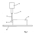
- a measurement force error map is generated for an object. This is achieved by mounting an analogue probe 10 on the quill 12 of a coordinate measuring machine (CMM) (not shown) as illustrated in Fig 1 .
- the analogue probe 10 has a deflectable stylus 14 with a workpiece contacting tip 16.
- the object 18 to be measured is mounted on the CMM machine table 20 and the probe 10 is driven slowly by the machine quill 12 in a path around the object.
- the object 18 is first scanned along a path at a first constant probe deflection, for example 300 ⁇ m.
- the object is then scanned along this path at one or more different subsequent probe deflections.
- the part may be scanned a second time with a probe deflection of 200 ⁇ m and a third time with a probe deflection of 100 ⁇ m.
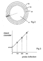
- Fig 2 shows a representation of the object 18 and the measurements obtained from the first 22, second 24 and third 26 scans around it. Each point on the object 18 will thus have three different measurements A,B,C, resulting from the three different scans at different probe deflections. For each point on the object, the measurements may be extrapolated back to calculate the measurement which would have been taken if the probe deflection was zero.
- Fig 3 shows a graph of the probe deflection against object diameter. The actual object diameter is shown at zero probe deflection.
- a passive probe is suitable for use in this method, such a probe may comprise a stylus deflectable against springs.
- This information enables a measurement force error map of the part to be produced. If the scans of the part were taken at a slow speed, this results in negligible dynamic errors due to very low accelerations of the probe and machine.
- Fig 4 shows the relationship of probe force against probe deflection.
- the probe acts within Hook's law such that when there is zero probe force, there is zero probe deflection.
- Fig 5 illustrates the relationship of radial error against probe deflection.
- Points A,B and C relate to the radial error at probe deflection 100 ⁇ m, 200 ⁇ m and 300 ⁇ m respectively. By using these points to extrapolate to zero probe deflection, zero radial error is achieved.
- a subsequent measurement taken at any probe deflection, for example point P may be corrected to zero radial error using this function.
- the function for correcting measurements at a given probe deflection is also linear.
- the measurement force error may be in the form of an error map. This could be in the form of a look-up table, with different error corrections for different stylus deflections.
- the error map could be in the form of a polynomial function.
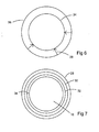
- Fig 6 shows the error corrections for points on the scan. Each point on the scan has a different radial correction 38 which is applied for a certain stylus deflection. If a subsequent object is scanned at a stylus deflection of 300 ⁇ m 36, the measurement force error function or map may be used to correct the measured dimensions 36 taken at this stylus deflection to the actual part dimensions 34 corresponding to the part being scanned at a deflection of 0 ⁇ m.
- Fig 16 illustrates a first scan profile 60 around an object 18 taken at constant deflection and a second scan profile 62 taken using a sinusoidally varying deflection. Points P1,P2,P3 on the object surface thus each have two measurements taken at different probe deflections. This measurement data may be extrapolated to zero as previously described.
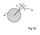
- Fig 17 illustrates a single scan profile 70 around an object 18, the scan profile 70 being taken using a sinusoidally varying stylus deflection.
- Fig 18 illustrates a section of the scan profile 70. Over a small angle 72, scan profile 70 contains many data points taken at different stylus deflections. Assuming changes in the surface are small over angle 72 (eg part deflection and uniformity of surface), these data points taken at different stylus deflections over angle 72 may be used for the extrapolation to zero calculation. This is also possible if there is a change in the surface profile over angle 72, as long as the change can be assumed to be linear.
- the object may be scanned several times with the probe having a different constant force for each scan.
- the object may be first scanned with a constant force between the stylus and the object of 0.3N.
- the object may then be scanned a second time with a constant force of 0.2N and a third time with a constant force of 0.1N.
- Each of these scans may have the same or different stylus deflections.
- Fig 7 shows a representation of the object 18 with an actual part dimension 34 and the measured dimensions obtained from the first 28, second 30 and third 32 scans at different constant probe forces.
- sufficient data may be collected from a single scan of varying probe force (eg having a sinusoidal profile) to do the extrapolate to zero calculation.
- This method is suitable for use in an active scanning probe, in which a motorised mechanism is used to control and modulate the contact force with the component to be measured.
- the object may comprise a part of a series of parts to be measured. In this case a measurement force error map of this part is produced by this method.
- the object may comprise an artefact having features corresponding to the features on the parts to be subsequently measured. These features may be, for example, spheres, ring gauges, plug gauges etc.
- Use of the artefact allows geometric errors in addition to the probing force measurement errors, to be determined.
- Geometric errors are errors of the machine and probe, for example non-linearity of the machine scales or the machine axes not being straight.
- the forms of the features on the artefact are known, they may be used to correct for geometric errors of the machine and probe. This may be done by comparing the extrapolated to zero data of the artefact with the known form of the artefact and producing a geometric error map to correct subsequent parts with.
- This method has the advantage that the errors due to probing force measurement errors and geometric errors can be separated. This would not be the case if, for example, measurement data from a scan with 300 ⁇ m deflection is compared with the known form of the artefact. In this case the probing force measurement error and geometric error would be combined into one correction and it would not be possible to separate them.
- This method of correcting for separate measurement force errors and geometric errors has the advantage that it takes into account the errors due to deflection of the object being measured. Objects with low stiffness and/or thin walls may deflect with the probing force whilst being measured.
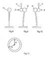
- Fig 8 illustrates a feature 50 to be measured which has low stiffness.
- the feature When the feature is contacted with a probe 10, as shown in Figs 9 and 10 , the feature deflects away from the probe. This deflection of the feature caused its diameter measured at force F to appear smaller than its actual diameter.
- Fig 11 illustrates the actual diameter 52 of the feature and the measured diameter 54 using a probe force F. Similarly, the inner diameter of a ring would appear larger than its actual diameter for the same reason. At zero probe deflection or zero probe force there will be zero deflection of the feature. Thus the measurement force error function or map created by the method of this invention takes account of these errors by this extrapolating to zero step.
- the dynamic errors of the system are determined. Dynamic errors may be caused, for example, by machine bending due to acceleration.
- the object is scanned at a high speed.
- the high speed scan is carried out at either constant probe deflection or constant force, as above.
- the high speed scan is preferably performed at a constant speed.
- the measurement data from this fast scan is compared with the measurement force error corrected slow scan relating to the actual dimensions of the object, produced as described in the first step of the invention.
- a dynamic error function or map may be produced by comparing the fast scan and the measurement error corrected slow scan. This dynamic error map is used to correct subsequent scans taken at a fast speed.
- the subsequent scans do not need to have the same stylus deflection or probe force as the original fast scans as the dynamic error function relates the error to the deflection or force. However it is desirable to use a similar fast speed for the subsequent scans.
- Fig 12 illustrates the measurements taken during the fast scan 40 and the actual dimension 42 of the object created by measurement force error correcting the slow scan as previously described.
- the dynamic error map has been combined with the measurement force error map or function to create a total feature map. This is done by adding the measurement force error correction vectors 38 around the part illustrated in Fig 6 with the dynamic error correction vectors around the part to create combined correction vectors 44 illustrated in Fig 12 .
- This method has the advantage that as the measurement errors are determined by scanning the object at different probe deflections or different forces, the measurement errors are known for every point on the surface of the object. Thus no interpolation is required.
- the measurement force errors and the dynamic errors may be determined in combination. Such a method will now be described with reference to Figs 13 and 14 .
- an object is scanned at a slow speed for example 10mm/s with a first deflection, for example 200 ⁇ m.
- Fig 13 shows the profile of the slow scan S1.
- the object is then scanned along the same path at a fast speed, for example 100mm/s and at a second deflection, for example 100 ⁇ m.
- Fig 13 shows the profile of the fast scan F1.
- the object is then scanned along the same path at the fast speed 100mm/s and at the first deflection 200 ⁇ m.
- Fig 13 shows the profile of the fast scan F2.
- Fig 14 shows a portion of the S1,F1 and F2 scan profiles around the object.
- F1 and F2 are profiles for scans of the same fast speed (100mm/s) but different deflections (100 ⁇ m and 200 ⁇ m respectively).
- the profile of the object for a high speed (100mm/s) scan with zero deflection can be determined. This profile is shown as HSZD on Fig 14 .
- the error due to deflection of the F2 scan may thus be determined. This deflection error is shown as e 1 , on Fig 14 .
- the deflection error e 1 may be applied to the profile of scan S1 to find the profile corresponding to a scan at low speed with zero deflection. This profile is shown as LSZD on Fig 14 and corresponds to the surface of the object.
- the LSZD is now used as a base line.
- the error between the LSZD baseline and the F2 scan is now determined. This is labelled e 2 on Fig 14 .
- the errors e 2 may be stored as a correction map or function.
- Subsequent objects may now be measured at a speed and deflection corresponding to scan F2 and corrected using the correction map or function.
- This method may be used with a force-measuring probe rather than a deflection-measuring probe.
- scans S1 and F2 are carried out at a first probe force and scan F1 is carried out at a second probe force.
- the two fast scans must then be extrapolated to zero force to determine the high speed zero force profile and thus the error due to force of the F2 scan may be determined.
- the measurements of the object during the S1,F1 and F2 scans may be determined by using either a scanning probe or a touch trigger probe.
- a touch trigger probe may be electronically loaded so that it triggers at a certain force.
- the probe is loaded to trigger at a first force and during the F1 scan the probe is loaded to trigger at a second force, enabling the two fast scans to extrapolate to zero force.
- the slow scan S1 it is not necessary for the slow scan S1 to have the same stylus deflection or probe force as the fast scan F1. This is because the relationship between stylus deflection/probe force and measurement error is determined at the fast speed from scans F1 and F2, which enables comparison with any stylus deflection/probe force at the slow speed.
- a third embodiment of the invention will now be described with reference to Fig 15 .
- a stylus 10 of a probe is driven into contact with a surface of an object 18 along a path 46 in a direction normal to the object's surface until a predetermined stylus force has been reached.
- This step is repeated along the same path for a plurality of different predetermined stylus forces.
- the measurement data along this path is used to extrapolate back to enable the point which would be measured with zero forces between the stylus and workpiece to be determined. This is the nominal object measurement.
- This process is repeated for a selection of datum points around the surface of the object.
- the data from each of these datum points is used to create an error map as previously described to correct subsequent measurements. Measurements of the surface of the object between the datum points are corrected by interpolating the error map between the datum points.
Applications Claiming Priority (3)
| Application Number | Priority Date | Filing Date | Title |
|---|---|---|---|
| GBGB0215478.9A GB0215478D0 (en) | 2002-07-04 | 2002-07-04 | Method of scanning a calibrating system |
| PCT/GB2003/002872 WO2004005849A1 (fr) | 2002-07-04 | 2003-07-04 | Procede d'etalonnage d'un systeme de balayage |
| EP03762783.3A EP1535026B1 (fr) | 2002-07-04 | 2003-07-04 | Procede d'etalonnage d'un systeme de balayage |
Related Parent Applications (3)
| Application Number | Title | Priority Date | Filing Date |
|---|---|---|---|
| EP03762783.3 Division | 2003-07-04 | ||
| EP03762783.3A Division EP1535026B1 (fr) | 2002-07-04 | 2003-07-04 | Procede d'etalonnage d'un systeme de balayage |
| EP03762783.3A Division-Into EP1535026B1 (fr) | 2002-07-04 | 2003-07-04 | Procede d'etalonnage d'un systeme de balayage |
Publications (3)
| Publication Number | Publication Date |
|---|---|
| EP2492636A2 true EP2492636A2 (fr) | 2012-08-29 |
| EP2492636A3 EP2492636A3 (fr) | 2012-10-24 |
| EP2492636B1 EP2492636B1 (fr) | 2019-01-09 |
Family
ID=9939829
Family Applications (2)
| Application Number | Title | Priority Date | Filing Date |
|---|---|---|---|
| EP03762783.3A Expired - Lifetime EP1535026B1 (fr) | 2002-07-04 | 2003-07-04 | Procede d'etalonnage d'un systeme de balayage |
| EP12169227.1A Expired - Lifetime EP2492636B1 (fr) | 2002-07-04 | 2003-07-04 | Procédé d'étalonnage d'un système de balayage |
Family Applications Before (1)
| Application Number | Title | Priority Date | Filing Date |
|---|---|---|---|
| EP03762783.3A Expired - Lifetime EP1535026B1 (fr) | 2002-07-04 | 2003-07-04 | Procede d'etalonnage d'un systeme de balayage |
Country Status (7)
| Country | Link |
|---|---|
| US (1) | US7254506B2 (fr) |
| EP (2) | EP1535026B1 (fr) |
| JP (1) | JP4638732B2 (fr) |
| CN (1) | CN1303398C (fr) |
| AU (1) | AU2003253104A1 (fr) |
| GB (1) | GB0215478D0 (fr) |
| WO (1) | WO2004005849A1 (fr) |
Cited By (1)
| Publication number | Priority date | Publication date | Assignee | Title |
|---|---|---|---|---|
| CN105841658A (zh) * | 2016-05-12 | 2016-08-10 | 四川大学 | 一种探针式轮廓仪形貌测量动态误差的控制方法 |
Families Citing this family (38)
| Publication number | Priority date | Publication date | Assignee | Title |
|---|---|---|---|---|
| US7543393B2 (en) | 2003-12-16 | 2009-06-09 | Renishaw Plc | Method of calibrating a scanning system |
| GB0329098D0 (en) | 2003-12-16 | 2004-01-21 | Renishaw Plc | Method of calibrating a scanning system |
| GB0417536D0 (en) * | 2004-08-06 | 2004-09-08 | Renishaw Plc | The use of surface measurement probes |
| GB2422015B (en) * | 2005-02-01 | 2007-02-28 | Taylor Hobson Ltd | A metrological instrument |
| GB0508395D0 (en) | 2005-04-26 | 2005-06-01 | Renishaw Plc | Method for scanning the surface of a workpiece |
| DE102005032749A1 (de) * | 2005-07-13 | 2007-01-18 | Carl Zeiss Industrielle Messtechnik Gmbh | Verfahren zum Antasten eines Werkstücks mit einem Koordinatenmessgerät und Koordinatenmessgeräte |
| GB2429291B (en) * | 2005-08-18 | 2008-08-20 | Taylor Hobson Ltd | A metrological apparatus |
| GB0608235D0 (en) * | 2006-04-26 | 2006-06-07 | Renishaw Plc | Differential calibration |
| JP5189806B2 (ja) * | 2006-09-07 | 2013-04-24 | 株式会社ミツトヨ | 表面形状測定装置 |
| GB0703423D0 (en) | 2007-02-22 | 2007-04-04 | Renishaw Plc | Calibration method and apparatus |
| EP2160565A1 (fr) * | 2007-06-28 | 2010-03-10 | Hexagon Metrology S.p.A. | Procédé de détermination des erreurs dynamiques dans une machine de mesure |
| US7912572B2 (en) * | 2007-09-20 | 2011-03-22 | General Electric Company | Calibration assembly for an inspection system |
| JP5192283B2 (ja) * | 2008-05-13 | 2013-05-08 | 株式会社ミツトヨ | 三次元測定機 |
| US8131654B2 (en) * | 2008-12-11 | 2012-03-06 | Pitney Bowes Inc. | System and method for dimensional rating of mail pieces |
| GB201003363D0 (en) * | 2010-03-01 | 2010-04-14 | Renishaw Plc | Measurement method and apparatus |
| GB201003599D0 (en) * | 2010-03-04 | 2010-04-21 | Renishaw Plc | Measurement method and apparatus |
| CN102072701A (zh) * | 2010-11-23 | 2011-05-25 | 苏州江城数控精密机械有限公司 | 一种检测零件尺寸的方法及装置 |
| CN102589503A (zh) * | 2011-01-18 | 2012-07-18 | 苏州春兴精工股份有限公司 | 基于短小圆弧的三坐标检测方法 |
| EP2492635B1 (fr) * | 2011-02-22 | 2013-05-29 | Siemens Aktiengesellschaft | Procédé de calibrage pour un palpeur de mesure sphérique |
| CN103782130B (zh) * | 2011-07-08 | 2017-06-20 | 卡尔蔡司工业测量技术有限公司 | 在测量工件的坐标时的误差修正和/或避免 |
| GB201113715D0 (en) | 2011-08-09 | 2011-09-21 | Renishaw Plc | Method and apparatus for inspecting workpieces |
| GB201503490D0 (en) * | 2015-03-02 | 2015-04-15 | Renishaw Plc | Calibration of dimensional measuring apparatus |
| EP2839240B1 (fr) | 2012-04-18 | 2017-09-06 | Renishaw PLC | Procédé de balayage de mesure analogique sur une machine-outil et machine-outil correspondante |
| IN2014DN08719A (fr) * | 2012-04-18 | 2015-05-22 | Renishaw Plc | |
| US10037017B2 (en) * | 2012-04-18 | 2018-07-31 | Renishaw Plc | Method of measurement on a machine tool and corresponding machine tool apparatus |
| JP6030339B2 (ja) | 2012-05-17 | 2016-11-24 | 株式会社ミツトヨ | 形状測定装置 |
| GB201308467D0 (en) | 2013-05-10 | 2013-06-19 | Renishaw Plc | Method and Apparatus for Inspecting Workpieces |
| GB201316329D0 (en) * | 2013-09-13 | 2013-10-30 | Renishaw Plc | A Method of Using a scanning probe |
| US9250055B2 (en) * | 2014-05-09 | 2016-02-02 | Mitutoyo Corporation | High speed contact detector for measurement sensors |
| CN104504197B (zh) * | 2014-12-21 | 2017-09-08 | 浙江省计量科学研究院 | 一种阿基米德螺旋线平面螺纹的偏心参量修正方法 |
| JP6774240B2 (ja) * | 2016-07-14 | 2020-10-21 | 株式会社ミツトヨ | 形状測定装置の制御方法 |
| GB201616415D0 (en) * | 2016-09-28 | 2016-11-09 | Renishaw Plc | A method and apparatus for measuring an object |
| EP3470777B1 (fr) * | 2017-10-10 | 2021-09-29 | Hexagon Technology Center GmbH | Système, méthode et produit programme informatique pour déterminer l'état d'une machine de positionnement d'outils |
| GB201908127D0 (en) | 2019-06-07 | 2019-07-24 | Renishaw Plc | Manufacturing method and apparatus |
| CN110977612B (zh) * | 2019-11-18 | 2021-08-03 | 上海爱堃智能系统有限公司 | Cnc数控加工在线测量误差修正方法及系统 |
| DE102020204313A1 (de) | 2020-04-02 | 2021-10-07 | Carl Zeiss Industrielle Messtechnik Gmbh | Verfahren zum Kalibrieren eines Schwenktasters |
| EP4212822A1 (fr) * | 2022-01-14 | 2023-07-19 | Renishaw PLC | Mappage de données d'erreur de capteur provenant d'une machine de positionnement par coordonnées |
| WO2023066936A1 (fr) * | 2021-10-19 | 2023-04-27 | Renishaw Plc | Cartographie de données d'erreur de capteur provenant d'une machine de positionnement par coordonnées |
Citations (1)
| Publication number | Priority date | Publication date | Assignee | Title |
|---|---|---|---|---|
| EP0318557A1 (fr) | 1987-06-11 | 1989-06-07 | Renishaw Plc | Procede d'inspection de pieces a usiner. |
Family Cites Families (10)
| Publication number | Priority date | Publication date | Assignee | Title |
|---|---|---|---|---|
| GB9224335D0 (en) * | 1992-11-20 | 1993-01-13 | Renishaw Metrology Ltd | A method of measuring workpieces using a surface contacting measuring probe |
| DE4436507A1 (de) * | 1994-10-13 | 1996-04-18 | Zeiss Carl Fa | Verfahren zur Koordinatenmessung an Werkstücken |
| US6131301A (en) | 1997-07-18 | 2000-10-17 | Renishaw Plc | Method of and apparatus for measuring workpieces using a coordinate positioning machine |
| GB9823228D0 (en) * | 1998-10-24 | 1998-12-16 | Renishaw Plc | Method of calibrating analogue probes |
| US6810597B2 (en) * | 1999-04-08 | 2004-11-02 | Renishaw Plc | Use of surface measuring probes |
| GB9907868D0 (en) * | 1999-04-08 | 1999-06-02 | Renishaw Plc | Method of calibrating a scanning system |
| DE10006753A1 (de) | 2000-02-15 | 2001-08-16 | Zeiss Carl | Dreh-Schwenkeinrichtung für den Tastkopf eines Koordinatenmeßgerätes |
| GB0210990D0 (en) * | 2002-05-14 | 2002-06-19 | Rolls Royce Plc | Method of generating an inspection program and method of generating a visual display |
| GB0317370D0 (en) * | 2003-07-24 | 2003-08-27 | Synaptics Uk Ltd | Magnetic calibration array |
| GB0322115D0 (en) * | 2003-09-22 | 2003-10-22 | Renishaw Plc | Method of error compensation |
-
2002
- 2002-07-04 GB GBGB0215478.9A patent/GB0215478D0/en not_active Ceased
-
2003
- 2003-07-04 CN CNB038156881A patent/CN1303398C/zh not_active Expired - Fee Related
- 2003-07-04 JP JP2004518952A patent/JP4638732B2/ja not_active Expired - Fee Related
- 2003-07-04 AU AU2003253104A patent/AU2003253104A1/en not_active Abandoned
- 2003-07-04 EP EP03762783.3A patent/EP1535026B1/fr not_active Expired - Lifetime
- 2003-07-04 WO PCT/GB2003/002872 patent/WO2004005849A1/fr active Application Filing
- 2003-07-04 EP EP12169227.1A patent/EP2492636B1/fr not_active Expired - Lifetime
- 2003-07-04 US US10/518,364 patent/US7254506B2/en not_active Expired - Lifetime
Patent Citations (1)
| Publication number | Priority date | Publication date | Assignee | Title |
|---|---|---|---|---|
| EP0318557A1 (fr) | 1987-06-11 | 1989-06-07 | Renishaw Plc | Procede d'inspection de pieces a usiner. |
Cited By (1)
| Publication number | Priority date | Publication date | Assignee | Title |
|---|---|---|---|---|
| CN105841658A (zh) * | 2016-05-12 | 2016-08-10 | 四川大学 | 一种探针式轮廓仪形貌测量动态误差的控制方法 |
Also Published As
| Publication number | Publication date |
|---|---|
| EP2492636B1 (fr) | 2019-01-09 |
| EP1535026A1 (fr) | 2005-06-01 |
| AU2003253104A1 (en) | 2004-01-23 |
| CN1666085A (zh) | 2005-09-07 |
| GB0215478D0 (en) | 2002-08-14 |
| US7254506B2 (en) | 2007-08-07 |
| JP4638732B2 (ja) | 2011-02-23 |
| WO2004005849A1 (fr) | 2004-01-15 |
| US20050213108A1 (en) | 2005-09-29 |
| CN1303398C (zh) | 2007-03-07 |
| EP1535026B1 (fr) | 2017-09-27 |
| JP2005531780A (ja) | 2005-10-20 |
| EP2492636A3 (fr) | 2012-10-24 |
Similar Documents
| Publication | Publication Date | Title |
|---|---|---|
| EP2492636B1 (fr) | Procédé d'étalonnage d'un système de balayage | |
| EP1700083B1 (fr) | Procede pour mesurer un objet | |
| US7543393B2 (en) | Method of calibrating a scanning system | |
| JP5042409B2 (ja) | 走査システムを校正する方法 | |
| TWI424164B (zh) | 差動校準 | |
| JP4504818B2 (ja) | 加工物検査方法 | |
| EP1792139B1 (fr) | Utilisation de sondes de mesure de surface | |
| EP1446636B2 (fr) | Comparaison d'objets dynamique | |
| EP1877732B1 (fr) | Etalonnage d'une sonde | |
| KR20050016971A (ko) | 스캐닝 시스템 교정 방법 |
Legal Events
| Date | Code | Title | Description |
|---|---|---|---|
| PUAI | Public reference made under article 153(3) epc to a published international application that has entered the european phase |
Free format text: ORIGINAL CODE: 0009012 |
|
| AC | Divisional application: reference to earlier application |
Ref document number: 1535026 Country of ref document: EP Kind code of ref document: P |
|
| AK | Designated contracting states |
Kind code of ref document: A2 Designated state(s): AT BE BG CH CY CZ DE DK EE ES FI FR GB GR HU IE IT LI LU MC NL PT RO SE SI SK TR |
|
| PUAL | Search report despatched |
Free format text: ORIGINAL CODE: 0009013 |
|
| AK | Designated contracting states |
Kind code of ref document: A3 Designated state(s): AT BE BG CH CY CZ DE DK EE ES FI FR GB GR HU IE IT LI LU MC NL PT RO SE SI SK TR |
|
| RIC1 | Information provided on ipc code assigned before grant |
Ipc: G01B 21/04 20060101AFI20120919BHEP |
|
| 17P | Request for examination filed |
Effective date: 20130424 |
|
| GRAP | Despatch of communication of intention to grant a patent |
Free format text: ORIGINAL CODE: EPIDOSNIGR1 |
|
| STAA | Information on the status of an ep patent application or granted ep patent |
Free format text: STATUS: GRANT OF PATENT IS INTENDED |
|
| INTG | Intention to grant announced |
Effective date: 20180620 |
|
| GRAS | Grant fee paid |
Free format text: ORIGINAL CODE: EPIDOSNIGR3 |
|
| GRAA | (expected) grant |
Free format text: ORIGINAL CODE: 0009210 |
|
| STAA | Information on the status of an ep patent application or granted ep patent |
Free format text: STATUS: THE PATENT HAS BEEN GRANTED |
|
| AC | Divisional application: reference to earlier application |
Ref document number: 1535026 Country of ref document: EP Kind code of ref document: P |
|
| AK | Designated contracting states |
Kind code of ref document: B1 Designated state(s): AT BE BG CH CY CZ DE DK EE ES FI FR GB GR HU IE IT LI LU MC NL PT RO SE SI SK TR |
|
| REG | Reference to a national code |
Ref country code: GB Ref legal event code: FG4D |
|
| REG | Reference to a national code |
Ref country code: CH Ref legal event code: EP Ref country code: AT Ref legal event code: REF Ref document number: 1087863 Country of ref document: AT Kind code of ref document: T Effective date: 20190115 |
|
| REG | Reference to a national code |
Ref country code: DE Ref legal event code: R096 Ref document number: 60351768 Country of ref document: DE |
|
| REG | Reference to a national code |
Ref country code: IE Ref legal event code: FG4D |
|
| REG | Reference to a national code |
Ref country code: NL Ref legal event code: MP Effective date: 20190109 |
|
| PG25 | Lapsed in a contracting state [announced via postgrant information from national office to epo] |
Ref country code: NL Free format text: LAPSE BECAUSE OF FAILURE TO SUBMIT A TRANSLATION OF THE DESCRIPTION OR TO PAY THE FEE WITHIN THE PRESCRIBED TIME-LIMIT Effective date: 20190109 |
|
| REG | Reference to a national code |
Ref country code: AT Ref legal event code: MK05 Ref document number: 1087863 Country of ref document: AT Kind code of ref document: T Effective date: 20190109 |
|
| PG25 | Lapsed in a contracting state [announced via postgrant information from national office to epo] |
Ref country code: FI Free format text: LAPSE BECAUSE OF FAILURE TO SUBMIT A TRANSLATION OF THE DESCRIPTION OR TO PAY THE FEE WITHIN THE PRESCRIBED TIME-LIMIT Effective date: 20190109 Ref country code: PT Free format text: LAPSE BECAUSE OF FAILURE TO SUBMIT A TRANSLATION OF THE DESCRIPTION OR TO PAY THE FEE WITHIN THE PRESCRIBED TIME-LIMIT Effective date: 20190509 Ref country code: SE Free format text: LAPSE BECAUSE OF FAILURE TO SUBMIT A TRANSLATION OF THE DESCRIPTION OR TO PAY THE FEE WITHIN THE PRESCRIBED TIME-LIMIT Effective date: 20190109 Ref country code: ES Free format text: LAPSE BECAUSE OF FAILURE TO SUBMIT A TRANSLATION OF THE DESCRIPTION OR TO PAY THE FEE WITHIN THE PRESCRIBED TIME-LIMIT Effective date: 20190109 |
|
| PG25 | Lapsed in a contracting state [announced via postgrant information from national office to epo] |
Ref country code: GR Free format text: LAPSE BECAUSE OF FAILURE TO SUBMIT A TRANSLATION OF THE DESCRIPTION OR TO PAY THE FEE WITHIN THE PRESCRIBED TIME-LIMIT Effective date: 20190410 Ref country code: BG Free format text: LAPSE BECAUSE OF FAILURE TO SUBMIT A TRANSLATION OF THE DESCRIPTION OR TO PAY THE FEE WITHIN THE PRESCRIBED TIME-LIMIT Effective date: 20190409 |
|
| REG | Reference to a national code |
Ref country code: DE Ref legal event code: R097 Ref document number: 60351768 Country of ref document: DE |
|
| PG25 | Lapsed in a contracting state [announced via postgrant information from national office to epo] |
Ref country code: EE Free format text: LAPSE BECAUSE OF FAILURE TO SUBMIT A TRANSLATION OF THE DESCRIPTION OR TO PAY THE FEE WITHIN THE PRESCRIBED TIME-LIMIT Effective date: 20190109 Ref country code: AT Free format text: LAPSE BECAUSE OF FAILURE TO SUBMIT A TRANSLATION OF THE DESCRIPTION OR TO PAY THE FEE WITHIN THE PRESCRIBED TIME-LIMIT Effective date: 20190109 Ref country code: DK Free format text: LAPSE BECAUSE OF FAILURE TO SUBMIT A TRANSLATION OF THE DESCRIPTION OR TO PAY THE FEE WITHIN THE PRESCRIBED TIME-LIMIT Effective date: 20190109 Ref country code: IT Free format text: LAPSE BECAUSE OF FAILURE TO SUBMIT A TRANSLATION OF THE DESCRIPTION OR TO PAY THE FEE WITHIN THE PRESCRIBED TIME-LIMIT Effective date: 20190109 Ref country code: RO Free format text: LAPSE BECAUSE OF FAILURE TO SUBMIT A TRANSLATION OF THE DESCRIPTION OR TO PAY THE FEE WITHIN THE PRESCRIBED TIME-LIMIT Effective date: 20190109 Ref country code: CZ Free format text: LAPSE BECAUSE OF FAILURE TO SUBMIT A TRANSLATION OF THE DESCRIPTION OR TO PAY THE FEE WITHIN THE PRESCRIBED TIME-LIMIT Effective date: 20190109 Ref country code: SK Free format text: LAPSE BECAUSE OF FAILURE TO SUBMIT A TRANSLATION OF THE DESCRIPTION OR TO PAY THE FEE WITHIN THE PRESCRIBED TIME-LIMIT Effective date: 20190109 |
|
| PLBE | No opposition filed within time limit |
Free format text: ORIGINAL CODE: 0009261 |
|
| STAA | Information on the status of an ep patent application or granted ep patent |
Free format text: STATUS: NO OPPOSITION FILED WITHIN TIME LIMIT |
|
| 26N | No opposition filed |
Effective date: 20191010 |
|
| PG25 | Lapsed in a contracting state [announced via postgrant information from national office to epo] |
Ref country code: SI Free format text: LAPSE BECAUSE OF FAILURE TO SUBMIT A TRANSLATION OF THE DESCRIPTION OR TO PAY THE FEE WITHIN THE PRESCRIBED TIME-LIMIT Effective date: 20190109 Ref country code: MC Free format text: LAPSE BECAUSE OF FAILURE TO SUBMIT A TRANSLATION OF THE DESCRIPTION OR TO PAY THE FEE WITHIN THE PRESCRIBED TIME-LIMIT Effective date: 20190109 |
|
| REG | Reference to a national code |
Ref country code: CH Ref legal event code: PL |
|
| GBPC | Gb: european patent ceased through non-payment of renewal fee |
Effective date: 20190704 |
|
| PG25 | Lapsed in a contracting state [announced via postgrant information from national office to epo] |
Ref country code: TR Free format text: LAPSE BECAUSE OF FAILURE TO SUBMIT A TRANSLATION OF THE DESCRIPTION OR TO PAY THE FEE WITHIN THE PRESCRIBED TIME-LIMIT Effective date: 20190109 |
|
| REG | Reference to a national code |
Ref country code: BE Ref legal event code: MM Effective date: 20190731 |
|
| PG25 | Lapsed in a contracting state [announced via postgrant information from national office to epo] |
Ref country code: GB Free format text: LAPSE BECAUSE OF NON-PAYMENT OF DUE FEES Effective date: 20190704 |
|
| PG25 | Lapsed in a contracting state [announced via postgrant information from national office to epo] |
Ref country code: BE Free format text: LAPSE BECAUSE OF NON-PAYMENT OF DUE FEES Effective date: 20190731 Ref country code: LI Free format text: LAPSE BECAUSE OF NON-PAYMENT OF DUE FEES Effective date: 20190731 Ref country code: CH Free format text: LAPSE BECAUSE OF NON-PAYMENT OF DUE FEES Effective date: 20190731 Ref country code: LU Free format text: LAPSE BECAUSE OF NON-PAYMENT OF DUE FEES Effective date: 20190704 |
|
| PG25 | Lapsed in a contracting state [announced via postgrant information from national office to epo] |
Ref country code: FR Free format text: LAPSE BECAUSE OF NON-PAYMENT OF DUE FEES Effective date: 20190731 |
|
| PG25 | Lapsed in a contracting state [announced via postgrant information from national office to epo] |
Ref country code: IE Free format text: LAPSE BECAUSE OF NON-PAYMENT OF DUE FEES Effective date: 20190704 |
|
| PG25 | Lapsed in a contracting state [announced via postgrant information from national office to epo] |
Ref country code: CY Free format text: LAPSE BECAUSE OF FAILURE TO SUBMIT A TRANSLATION OF THE DESCRIPTION OR TO PAY THE FEE WITHIN THE PRESCRIBED TIME-LIMIT Effective date: 20190109 |
|
| PG25 | Lapsed in a contracting state [announced via postgrant information from national office to epo] |
Ref country code: HU Free format text: LAPSE BECAUSE OF FAILURE TO SUBMIT A TRANSLATION OF THE DESCRIPTION OR TO PAY THE FEE WITHIN THE PRESCRIBED TIME-LIMIT; INVALID AB INITIO Effective date: 20030704 |
|
| PGFP | Annual fee paid to national office [announced via postgrant information from national office to epo] |
Ref country code: DE Payment date: 20220727 Year of fee payment: 20 |
|
| REG | Reference to a national code |
Ref country code: DE Ref legal event code: R071 Ref document number: 60351768 Country of ref document: DE |
|
| P01 | Opt-out of the competence of the unified patent court (upc) registered |
Effective date: 20230602 |