EP2492422A1 - Verschlussmechanismus einer Klappe, und Abfallsammelbehälter, der mit einer mit einem solchen Mechanismus verschließbaren Klappe ausgestattet ist - Google Patents
Verschlussmechanismus einer Klappe, und Abfallsammelbehälter, der mit einer mit einem solchen Mechanismus verschließbaren Klappe ausgestattet ist Download PDFInfo
- Publication number
- EP2492422A1 EP2492422A1 EP12157390A EP12157390A EP2492422A1 EP 2492422 A1 EP2492422 A1 EP 2492422A1 EP 12157390 A EP12157390 A EP 12157390A EP 12157390 A EP12157390 A EP 12157390A EP 2492422 A1 EP2492422 A1 EP 2492422A1
- Authority
- EP
- European Patent Office
- Prior art keywords
- hatch
- lock
- locking mechanism
- retaining element
- opening
- Prior art date
- Legal status (The legal status is an assumption and is not a legal conclusion. Google has not performed a legal analysis and makes no representation as to the accuracy of the status listed.)
- Granted
Links
Images


Classifications
-
- E—FIXED CONSTRUCTIONS
- E05—LOCKS; KEYS; WINDOW OR DOOR FITTINGS; SAFES
- E05B—LOCKS; ACCESSORIES THEREFOR; HANDCUFFS
- E05B63/00—Locks or fastenings with special structural characteristics
- E05B63/18—Locks or fastenings with special structural characteristics with arrangements independent of the locking mechanism for retaining the bolt or latch in the retracted position
- E05B63/185—Preventing actuation of a bolt when the wing is open
-
- B—PERFORMING OPERATIONS; TRANSPORTING
- B65—CONVEYING; PACKING; STORING; HANDLING THIN OR FILAMENTARY MATERIAL
- B65F—GATHERING OR REMOVAL OF DOMESTIC OR LIKE REFUSE
- B65F1/00—Refuse receptacles; Accessories therefor
- B65F1/14—Other constructional features; Accessories
- B65F1/16—Lids or covers
- B65F1/1615—Lids or covers with means for locking, fastening or permanently closing thereof
-
- E—FIXED CONSTRUCTIONS
- E05—LOCKS; KEYS; WINDOW OR DOOR FITTINGS; SAFES
- E05C—BOLTS OR FASTENING DEVICES FOR WINGS, SPECIALLY FOR DOORS OR WINDOWS
- E05C3/00—Fastening devices with bolts moving pivotally or rotatively
- E05C3/02—Fastening devices with bolts moving pivotally or rotatively without latching action
- E05C3/04—Fastening devices with bolts moving pivotally or rotatively without latching action with operating handle or equivalent member rigid with the bolt
- E05C3/041—Fastening devices with bolts moving pivotally or rotatively without latching action with operating handle or equivalent member rigid with the bolt rotating about an axis perpendicular to the surface on which the fastener is mounted
Definitions
- the present invention relates to the field of mechanisms comprising a lock for locking all types of traps and doors.
- the present invention finds an advantageous, but in no way exclusive, application in the field of waste collection by means of voluntary delivery containers.
- the containers of voluntary contribution are containers installed on the public road, at the disposal of the users who can thus bring their sorted waste there and their garbage. It is now customary to collect household waste and selected waste such as glass, packaging, paper and so on.
- Voluntary containers are generally of three types: aerial, buried or semi-buried. The last two categories include containers where all or most of the storage volume is underground, with the aim of minimizing congestion and the visual impact of containers on the landscape.
- the "air” type containers are simply placed on the ground and all of their storage volume is above ground.
- a voluntary intake container has one or more openings of shape and dimensions adapted to the type of waste to which the container is dedicated.
- an orifice of circular section of diameter compatible with the current dimensions of the glass bottles.
- an oblong section orifice sized for the introduction of newspapers, magazines, etc.
- an additional hatch serving as inspection hatch and / or trap large bulky waste.
- Such a hatch generally has larger dimensions than the main opening, and is provided with a locking means, for example a key lock.
- the additional hatch is in the form of a panel articulated on the terminal, this panel being sometimes configured so that it carries the main opening.
- a key is generally entrusted to authorized persons, for example the maintenance agents who have to intervene on the container or persons belonging to entities producing large quantities of waste (businesses, administrations, communities, etc.).
- a commonly used locking means is a so-called captive key lock, most often of the "quarter turn” type.
- This system has the particular advantage of preventing a user from losing the key he has. Indeed, to introduce waste via the hatch, it is necessary to introduce the key in the lock, to rotate it to the unlocking point, then open the hatch and released. In this configuration, the key is locked in the lock and can not be removed. To be able to remove the key, it is necessary to return to the angular locking position of the lock, that is to say the initial position of insertion of the key.
- the present invention aims to overcome this deficiency by providing a locking mechanism that can equip all types of lockable door, so that the hatch thus equipped can in no case be abandoned in the open position.
- the term trap covers both small and large openings, including doors.
- the invention provides a locking mechanism of a door having a lock that can return to its locking position, and therefore the removal of the key, only if the door is in the closed position.
- the object of the invention is achieved thanks to the retaining means activated by the activation means during the opening of the hatch, and deactivated by these same means when closing thereof.
- the retaining means When they are activated, that is to say as soon as the hatch is open and until it is closed, the retaining means prevent any movement of the lock tending to bring it back to its position of locking.
- the closed position there is only one and only position of the hatch in which it is allowed to introduce or remove a key: the closed position.
- the invention also relates to a voluntary intake container for the collection of waste, comprising a hatch provided with a locking mechanism as defined above.
- the voluntary intake container is equipped with a locking mechanism whose activation means comprise a tooth as defined above, the container having a body which is secured to said tooth.
- the container hatch can be pivotally or slidably mounted on the container body.
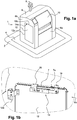
- the figure 1a is a perspective view of a container equipped with a lockable hatch.
- container 1 is of the buried type. It comprises, in known manner, a buried tank 4 flush with the ground 2, and a terminal 6 waste introduction. Conventionally, the container 1 is provided with a gripping device 8 for lifting the container, in particular to ensure its regular emptying.
- the terminal 6 comprises a front face 6a on which opens an opening for introducing waste into the tank 4.
- the container 1 is dedicated to the collection of household waste and the introduction opening is accessible by means of a drum 10.
- the terminal 6 further comprises an additional hatch, serving in the example of inspection hatch and / or trap large bulky waste.
- This hatch is located in the example on a side face 6b of the terminal. It is formed of a hatch panel 12 articulated on the front face 6a, by means of hinges 12a, one of which is visible on the figure 1b .
- the panel 12 in the example of generally rectangular shape, is provided with a locking mechanism 14 comprising a key lock 14a, type "captive key".
- a key lock 14a type "captive key”.
- an authorized person, possessing a key is in the possibility of unlocking the hatch and opening it in order to access an opening of dimensions greater than those of the opening accessible in the drum 10.
- the lock 14a is disposed near the upper edge 12b of the panel 12, and also close to the edge 12c located opposite the pivot axis of the hinges 12a.
- the lock 14a constitutes the part visible from the outside of the locking mechanism 14 represented on the Figures 1a to 4d .
- said mechanism disposed on the inner face of the panel 12, is therefore invisible from the outside the container.
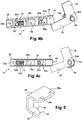
- the locking mechanism 14 shown on the figure 2a is viewed in perspective, the observation point being located on the inner side of the panel 12 (not shown), opposite the key introduction port.
- Said mechanism comprises a locking bolt 16, integral in rotation with an operating member, or driving cylinder (or barrel), of the lock 14a.
- the operation of the bolt is controlled by the lock 14a: when the lock is in the locked position, the bolt 16 is in a locking position which prevents the opening of the panel 12, and when the lock is in the unlocked position, the bolt 16 is in an unlocking position that allows the opening of the panel 12.
- the bolt joins one or other of these positions by a rotational movement about an axis XX coincides with the axis of rotation of the body of maneuver, or barrel, of the lock 14a.
- the bolt is in the unlocked position, it is retracted and no longer forms a projection from the edge 12b of the panel 12. It therefore allows the opening of the hatch.
- the bolt 16 has a generally parallelepiped shape. Its section in a plane perpendicular to the axis of rotation of the driving cylinder of the lock (axis XX on the figure 2a ) is of generally rectangular shape. In this case, the bolt 16 has an edge 16a forming a long side of length H and an edge 16b forming a short side of length L. In the example, the bolt is constituted by a thin plate. This plate is for example made of metal. The dimensions of the bolt 16, in particular its thickness, are of course compatible with the dimensions of the slot 7a.
- retaining means Near the bolt 16 are arranged retaining means. These means comprise a retaining element 18, mounted in translation on a support 20, the support 20 being fixed on the inner face of the panel 12, for example by means of screws passing through fixing holes 20a. A protective element 22 is fixed to the support 20 so as to form with it a housing containing the retaining means.
- the support 20 and the protection element 22 are two elongate elements with a "U" -shaped section. They are assembled mutually so as to form a housing within which the retaining element 18 slides.
- the protection element 22 is fixed to the support 20 by means of screws 23, cooperating with threaded studs 20b, visible in particular on the figure 2b , on which the protective element 22 is removed (for a better understanding, the protection element 22 is only shown on the figures 1b and 2a ).
- These pads are integral with the support 20 and projecting therefrom.
- the retaining element 18, also having a generally U-shaped section comprises two windows 18a, each window being crossed by one of the studs tapped 20b. The dimensions of each window 18a, in particular their dimension along the sliding axis of the retaining element 18, are such that they do not hinder the free movement of the retaining element 18.
- the retaining means also comprise elastic return means urging the retaining element 18 towards a locking position, this bias tending to bring the retaining element 18 closer to the axis of rotation of the drive cylinder of the lock 14a. , in a plane perpendicular to this axis.
- the elastic return means comprise a cylindrical compression spring 19 bearing at one of its ends on a threaded stud 20b of the support 20 and, at the opposite end, on the retaining element 18. So, as we can see on the Figure 2c the spring 19 tends to bring the retaining element 18 to the right of the figure.
- a stop finger 24 is also integral with the drive cylinder of the lock 14a.
- the stop finger is elongate in a direction perpendicular to the elongation direction of the bolt 16, and also perpendicular to the axis XX of rotation of the drive cylinder of the lock 14a.
- the stop finger 24 is of generally parallelepipedal shape and its section in a plane perpendicular to the axis of rotation of the drive cylinder of the lock 14a is of generally rectangular shape.
- the stop finger 24 has an edge 24a a long side of length D and an edge 24b forming a short side 24b of length E.
- the bolt 16 and the stop finger 24 are formed by a single piece in the shape of "L”, pierced with a fixing hole, and secured to the drive cylinder of the lock 14a to by means of a screw 26.
- An eccentric hole 26a forming a rotational stop element is also provided in the "L” shaped piece, in order to prevent any rotation of the bolt relative to the drive cylinder of the lock 14a. .
- the distance F between the axis of rotation XX and the distal edge 24b of the stop finger 24 is strictly greater than the distance G between the axis of rotation XX and the distal edge 16b of the bolt 16.
- the locking mechanism according to the invention also comprises means for activating the retaining means.
- These activation means comprise a support 28 which carries a visible tooth 30, in particular on the figure 5 .
- the tooth 30 has at its free end a beveled portion 32 forming an inclined ramp, extending towards the end embedded in the support 28 by a straight portion 34.
- the support 28 is fixed rigidly to the edge 7 of the body 6 of the terminal of the container, and has for this purpose fixing holes 28a.
- the inclined ramp 32 is intended to cooperate with the retaining element 18, through a slot 22a formed on the protective element 22.
- the light 22a has a shape and dimensions allowing the passage of the tooth 30.
- the mechanism is in the locked state.
- the bolt 16 is in the locking position and the retaining element 18 is in the unlocking position.
- the retaining element 18 is recessed: it is distant relative to the axis of rotation XX and is not likely, in this position, to hinder the movement of the stop finger 24 (and bolt 16), as visible on the Figures 2b and 2c .
- the retaining element 18 In the locked state, the retaining element 18 is held in its unblocking position by the tooth 30 which, through the slot 22a of the closure element 22, presses, via the straight portion 34 , on a bearing surface of the retaining element 18.
- This bearing surface is constituted in the example by a tongue 18b, which is elongate in a direction perpendicular to the translation axis of the retaining element 18, or is slightly inclined with respect to this direction.
- a clear space is formed opposite the tongue 18b, in the example by a window 18c formed in the retaining element, to allow the housing of the tooth 30.
- the force generated by the support of the tooth 30 on the tongue 18b is substantially of the same direction as the force applied by the spring 19, but of opposite direction.
- the tongue 18b also serves to support the spring 19, the latter bearing on one side of the tongue located on the opposite side to the bearing surface of the tooth 30.
- FIGS. 3a and 3b show the mechanism being unlocked.
- the hatch is still closed, but a key has been inserted in the lock 14a to cause the bolt 16 to rotate.
- the retaining element 18 does not prevent rotation of the stop pin 24. and therefore of the bolt 16.
- the unlocked position of the lock 14a which requires in the example a rotation of about 90 °, the bolt 16 is in its unlocked position, and it is now possible to open the hatch.
- the retaining element remains in the unlocking position, under the action of the tooth 30, as long as the hatch is not open.
- FIGS. 4a to 4c show the locking mechanism when the hatch is open.
- the opening of the hatch causes the edge 12b of the panel 12 of the edge 7 to move away from each other.
- This distance has the consequence that the tooth 30, fixed relative to the body of the terminal, stops pressing the tab 18b of the retaining element 18.
- the retaining element 18 is then subject only to the force of the elastic return means (the spring 19), which push the retaining element 18 to its position. blocking, as can be seen by comparison of figures 3a and 4b .
- the retaining element when opening the hatch, the retaining element is moved from its unlocking position to its locking position, by a translational movement direction perpendicular to the axis XX.
- These two positions are determined so that the retaining element 18 constitutes an obstacle to the rotation of the stop finger 24 (as visible on the Figures 4b and 4c ) when the retaining element is in the locking position, and it does not oppose the passage of the stop finger 24 when in the unlocking position (as visible on the figures 2b and 3b ).
- the unlocking position is imposed by the tooth 30, as visible in particular on the figure 3b
- the locking position is imposed by the threaded studs 20b which form stops of the retaining element 18, as visible on the figure 4a to 4c .
- the blocking position must further allow the passage of the bolt 16 while prohibiting the passage of the stop finger 24, as visible on the Figures 4b and 4c .
- the amplitude of the translational movement of the retaining element 18 is less than the difference between, on the one hand, the distance F between the axis of rotation XX and the edge 24b distal of the stop finger 24 and, on the other hand, the distance G between the axis of rotation XX and the distal edge 16b of the bolt 16.
- the opening of the trap automatically forces the retaining element to take its blocking position.
- the retaining element is opposed to the passage of the stop finger if one tries to drive the lock 14a to its initial position, which therefore prevents any removal of the key.
- the tooth 30 presses again on the tongue 18b of the retaining element 18 via the inclined ramp 32, which acts on said tongue 18b like a cam by pushing the retaining element 18 to its end. unlocking position.
- the retaining element 18 then stops the finger from returning to its initial position, corresponding to the locking position of the lock shown on the Figures 2a to 2c .
- the invention thus achieves its objective by preventing any premature removal of the key when a user manipulates the hatch: removal of the key is possible only if the hatch is in the closed position. As soon as it is no longer in the closed position, any removal of the key automatically becomes impossible.
- This objective is further achieved by the arrangement of mechanical parts that are not very complex and therefore inexpensive and reliable. The invention is therefore particularly convenient to manufacture, to install on an existing hatch and to use.
- the invention is particularly reliable and suitable for the field of voluntary containers, or any other outdoor system to have a long life while requiring almost no maintenance.
- the invention finds an advantageous application in the field of voluntary delivery containers, application which is the subject of the example given above. However, it is clear that the invention finds application in all areas where it is necessary to provide the locking of a door or hatch.
Landscapes
- Engineering & Computer Science (AREA)
- Mechanical Engineering (AREA)
- Structural Engineering (AREA)
- Refuse Receptacles (AREA)
- Lock And Its Accessories (AREA)
Applications Claiming Priority (1)
| Application Number | Priority Date | Filing Date | Title |
|---|---|---|---|
| FR1151622A FR2972018B1 (fr) | 2011-02-28 | 2011-02-28 | Mecanisme de verrouillage d'une trappe et conteneur de collecte de dechets pourvu d'une trappe verrouillable au moyen d'un tel mecanisme |
Publications (2)
| Publication Number | Publication Date |
|---|---|
| EP2492422A1 true EP2492422A1 (de) | 2012-08-29 |
| EP2492422B1 EP2492422B1 (de) | 2016-12-28 |
Family
ID=45688387
Family Applications (1)
| Application Number | Title | Priority Date | Filing Date |
|---|---|---|---|
| EP12157390.1A Active EP2492422B1 (de) | 2011-02-28 | 2012-02-28 | Verschlussmechanismus einer Klappe, und Abfallsammelbehälter, der mit einer mit einem solchen Mechanismus verschließbaren Klappe ausgestattet ist |
Country Status (2)
| Country | Link |
|---|---|
| EP (1) | EP2492422B1 (de) |
| FR (1) | FR2972018B1 (de) |
Cited By (1)
| Publication number | Priority date | Publication date | Assignee | Title |
|---|---|---|---|---|
| CN115045568A (zh) * | 2022-05-24 | 2022-09-13 | 杭州齐丰科技有限公司 | 一种洗瓶机自动门锁结构 |
Families Citing this family (1)
| Publication number | Priority date | Publication date | Assignee | Title |
|---|---|---|---|---|
| CN110077765A (zh) * | 2019-04-23 | 2019-08-02 | 成都市云海天环保科技有限公司 | 一种多功能投料箱 |
Citations (5)
| Publication number | Priority date | Publication date | Assignee | Title |
|---|---|---|---|---|
| DE144512C (de) * | ||||
| FR2749569A1 (fr) * | 1996-06-07 | 1997-12-12 | Stasiak Michel | Dispositif de collecte de seringues usagees et d'articles similaires |
| US6658903B1 (en) * | 2000-09-27 | 2003-12-09 | Mcshane James P. | Thermally insulated lock box and lock therefor |
| US20040160130A1 (en) * | 2003-01-21 | 2004-08-19 | Eckerdt George H. | Door key retention security system |
| FR2913962A1 (fr) * | 2007-03-20 | 2008-09-26 | Multi Com Affichage Sarl | Mobilier urbain utilisable pour la collecte d'objets de petites dimensions. |
-
2011
- 2011-02-28 FR FR1151622A patent/FR2972018B1/fr active Active
-
2012
- 2012-02-28 EP EP12157390.1A patent/EP2492422B1/de active Active
Patent Citations (5)
| Publication number | Priority date | Publication date | Assignee | Title |
|---|---|---|---|---|
| DE144512C (de) * | ||||
| FR2749569A1 (fr) * | 1996-06-07 | 1997-12-12 | Stasiak Michel | Dispositif de collecte de seringues usagees et d'articles similaires |
| US6658903B1 (en) * | 2000-09-27 | 2003-12-09 | Mcshane James P. | Thermally insulated lock box and lock therefor |
| US20040160130A1 (en) * | 2003-01-21 | 2004-08-19 | Eckerdt George H. | Door key retention security system |
| FR2913962A1 (fr) * | 2007-03-20 | 2008-09-26 | Multi Com Affichage Sarl | Mobilier urbain utilisable pour la collecte d'objets de petites dimensions. |
Cited By (1)
| Publication number | Priority date | Publication date | Assignee | Title |
|---|---|---|---|---|
| CN115045568A (zh) * | 2022-05-24 | 2022-09-13 | 杭州齐丰科技有限公司 | 一种洗瓶机自动门锁结构 |
Also Published As
| Publication number | Publication date |
|---|---|
| FR2972018B1 (fr) | 2014-03-14 |
| FR2972018A1 (fr) | 2012-08-31 |
| EP2492422B1 (de) | 2016-12-28 |
Similar Documents
| Publication | Publication Date | Title |
|---|---|---|
| EP4003866B1 (de) | Sicherheitsverschluss | |
| EP1941821A1 (de) | Verteiler von nebeneinander angeordneten Rollen, der mit einer unteren Schiebeverschlussklappe ausgestattet ist | |
| CA2348711A1 (fr) | Dispositif automatique par gravite de verrouillage/deverrouillage du couvercle d'un bac et bac equipe d'un tel dispositif | |
| FR2762306A1 (fr) | Dispositif de verrouillage du couvercle d'un bac et bac ainsi equipe | |
| WO2004067399A1 (fr) | Bouchon de fermeture d'un flacon, a ouverture controlee | |
| FR2790784A1 (fr) | Dispositif de securite pour porte destine a empecher le coincement des doigts du cote des charnieres | |
| EP1882779A1 (de) | Vorrichtung zum Verriegeln und Entriegeln einer Abdeckung oder eines Deckels auf einem Rahmen mit Hilfe eines Schlüssels, insbesondere von Fahrbahnschachtabdeckungen | |
| EP2492422B1 (de) | Verschlussmechanismus einer Klappe, und Abfallsammelbehälter, der mit einer mit einem solchen Mechanismus verschließbaren Klappe ausgestattet ist | |
| EP1820924A1 (de) | Magnetisches Schließsystem für Zugangsklappe oder -tür | |
| FR3016652A1 (fr) | Dispositif de verrouillage et deverrouillage inviolable a clef amovible pour ouvrant | |
| FR2957109A1 (fr) | Dispositif de verrouillage/deverrouillage a inviolabilite amelioree et sa cle pour tampon et piece de fonderie a ouvrant | |
| FR2914001A1 (fr) | Systeme de verrouillage pour espagnolette | |
| EP4108856B1 (de) | Steuerungsvorrichtung eines verriegelungs-/entriegelungssystems eines öffnungsflügels und entsprechender tür-/fensterrahmen | |
| EP1854942B1 (de) | Vorrichtung zur Zugangsbeschränkung zum Schloss eines Verriegelungsmechanismus, insbesondere einer Drehsperre | |
| FR3068062A1 (fr) | Dispositif de blocage | |
| FR2871509A1 (fr) | Portillon pour barriere de protection de piscine | |
| BE1017308A5 (fr) | Serrure. | |
| EP0621048A1 (de) | Behälter für infizierte medizinische Gegenstände | |
| EP4481139B1 (de) | Beckenabdeckungsverriegelung | |
| EP1396446A1 (de) | Vorrichtung zum Ver-/Entriegeln des Deckels eines Müllbehälters | |
| FR2966136A1 (fr) | Conteneur de collecte de dechets muni d'un systeme de securite enfant | |
| FR2629510A1 (fr) | Arret de vent pour battants de volets de portes, portes-fenetres, fenetres ou autres | |
| FR2963634A1 (fr) | Serrure de porte comprenant un dispositif de protection de gorge | |
| EP3819445A1 (de) | Sicherheitsvorrichtung für fenstergriff | |
| FR2739892A1 (fr) | Dispositif de securite pour porte incorporant un entrebailleur |
Legal Events
| Date | Code | Title | Description |
|---|---|---|---|
| PUAI | Public reference made under article 153(3) epc to a published international application that has entered the european phase |
Free format text: ORIGINAL CODE: 0009012 |
|
| AK | Designated contracting states |
Kind code of ref document: A1 Designated state(s): AL AT BE BG CH CY CZ DE DK EE ES FI FR GB GR HR HU IE IS IT LI LT LU LV MC MK MT NL NO PL PT RO RS SE SI SK SM TR |
|
| AX | Request for extension of the european patent |
Extension state: BA ME |
|
| 17P | Request for examination filed |
Effective date: 20130228 |
|
| 17Q | First examination report despatched |
Effective date: 20130410 |
|
| GRAP | Despatch of communication of intention to grant a patent |
Free format text: ORIGINAL CODE: EPIDOSNIGR1 |
|
| INTG | Intention to grant announced |
Effective date: 20160712 |
|
| GRAS | Grant fee paid |
Free format text: ORIGINAL CODE: EPIDOSNIGR3 |
|
| GRAA | (expected) grant |
Free format text: ORIGINAL CODE: 0009210 |
|
| AK | Designated contracting states |
Kind code of ref document: B1 Designated state(s): AL AT BE BG CH CY CZ DE DK EE ES FI FR GB GR HR HU IE IS IT LI LT LU LV MC MK MT NL NO PL PT RO RS SE SI SK SM TR |
|
| REG | Reference to a national code |
Ref country code: GB Ref legal event code: FG4D Free format text: NOT ENGLISH |
|
| REG | Reference to a national code |
Ref country code: CH Ref legal event code: EP |
|
| REG | Reference to a national code |
Ref country code: AT Ref legal event code: REF Ref document number: 857444 Country of ref document: AT Kind code of ref document: T Effective date: 20170115 |
|
| REG | Reference to a national code |
Ref country code: IE Ref legal event code: FG4D Free format text: LANGUAGE OF EP DOCUMENT: FRENCH |
|
| REG | Reference to a national code |
Ref country code: DE Ref legal event code: R096 Ref document number: 602012027012 Country of ref document: DE |
|
| REG | Reference to a national code |
Ref country code: FR Ref legal event code: PLFP Year of fee payment: 6 |
|
| PG25 | Lapsed in a contracting state [announced via postgrant information from national office to epo] |
Ref country code: LV Free format text: LAPSE BECAUSE OF FAILURE TO SUBMIT A TRANSLATION OF THE DESCRIPTION OR TO PAY THE FEE WITHIN THE PRESCRIBED TIME-LIMIT Effective date: 20161228 |
|
| REG | Reference to a national code |
Ref country code: NL Ref legal event code: FP |
|
| REG | Reference to a national code |
Ref country code: LT Ref legal event code: MG4D |
|
| PG25 | Lapsed in a contracting state [announced via postgrant information from national office to epo] |
Ref country code: NO Free format text: LAPSE BECAUSE OF FAILURE TO SUBMIT A TRANSLATION OF THE DESCRIPTION OR TO PAY THE FEE WITHIN THE PRESCRIBED TIME-LIMIT Effective date: 20170328 Ref country code: GR Free format text: LAPSE BECAUSE OF FAILURE TO SUBMIT A TRANSLATION OF THE DESCRIPTION OR TO PAY THE FEE WITHIN THE PRESCRIBED TIME-LIMIT Effective date: 20170329 Ref country code: SE Free format text: LAPSE BECAUSE OF FAILURE TO SUBMIT A TRANSLATION OF THE DESCRIPTION OR TO PAY THE FEE WITHIN THE PRESCRIBED TIME-LIMIT Effective date: 20161228 Ref country code: LT Free format text: LAPSE BECAUSE OF FAILURE TO SUBMIT A TRANSLATION OF THE DESCRIPTION OR TO PAY THE FEE WITHIN THE PRESCRIBED TIME-LIMIT Effective date: 20161228 |
|
| REG | Reference to a national code |
Ref country code: AT Ref legal event code: MK05 Ref document number: 857444 Country of ref document: AT Kind code of ref document: T Effective date: 20161228 |
|
| PG25 | Lapsed in a contracting state [announced via postgrant information from national office to epo] |
Ref country code: FI Free format text: LAPSE BECAUSE OF FAILURE TO SUBMIT A TRANSLATION OF THE DESCRIPTION OR TO PAY THE FEE WITHIN THE PRESCRIBED TIME-LIMIT Effective date: 20161228 Ref country code: BE Free format text: LAPSE BECAUSE OF NON-PAYMENT OF DUE FEES Effective date: 20170228 Ref country code: HR Free format text: LAPSE BECAUSE OF FAILURE TO SUBMIT A TRANSLATION OF THE DESCRIPTION OR TO PAY THE FEE WITHIN THE PRESCRIBED TIME-LIMIT Effective date: 20161228 Ref country code: RS Free format text: LAPSE BECAUSE OF FAILURE TO SUBMIT A TRANSLATION OF THE DESCRIPTION OR TO PAY THE FEE WITHIN THE PRESCRIBED TIME-LIMIT Effective date: 20161228 |
|
| PG25 | Lapsed in a contracting state [announced via postgrant information from national office to epo] |
Ref country code: SK Free format text: LAPSE BECAUSE OF FAILURE TO SUBMIT A TRANSLATION OF THE DESCRIPTION OR TO PAY THE FEE WITHIN THE PRESCRIBED TIME-LIMIT Effective date: 20161228 Ref country code: EE Free format text: LAPSE BECAUSE OF FAILURE TO SUBMIT A TRANSLATION OF THE DESCRIPTION OR TO PAY THE FEE WITHIN THE PRESCRIBED TIME-LIMIT Effective date: 20161228 Ref country code: IS Free format text: LAPSE BECAUSE OF FAILURE TO SUBMIT A TRANSLATION OF THE DESCRIPTION OR TO PAY THE FEE WITHIN THE PRESCRIBED TIME-LIMIT Effective date: 20170428 Ref country code: CZ Free format text: LAPSE BECAUSE OF FAILURE TO SUBMIT A TRANSLATION OF THE DESCRIPTION OR TO PAY THE FEE WITHIN THE PRESCRIBED TIME-LIMIT Effective date: 20161228 Ref country code: RO Free format text: LAPSE BECAUSE OF FAILURE TO SUBMIT A TRANSLATION OF THE DESCRIPTION OR TO PAY THE FEE WITHIN THE PRESCRIBED TIME-LIMIT Effective date: 20161228 |
|
| PG25 | Lapsed in a contracting state [announced via postgrant information from national office to epo] |
Ref country code: PT Free format text: LAPSE BECAUSE OF FAILURE TO SUBMIT A TRANSLATION OF THE DESCRIPTION OR TO PAY THE FEE WITHIN THE PRESCRIBED TIME-LIMIT Effective date: 20170428 Ref country code: PL Free format text: LAPSE BECAUSE OF FAILURE TO SUBMIT A TRANSLATION OF THE DESCRIPTION OR TO PAY THE FEE WITHIN THE PRESCRIBED TIME-LIMIT Effective date: 20161228 Ref country code: SM Free format text: LAPSE BECAUSE OF FAILURE TO SUBMIT A TRANSLATION OF THE DESCRIPTION OR TO PAY THE FEE WITHIN THE PRESCRIBED TIME-LIMIT Effective date: 20161228 Ref country code: BG Free format text: LAPSE BECAUSE OF FAILURE TO SUBMIT A TRANSLATION OF THE DESCRIPTION OR TO PAY THE FEE WITHIN THE PRESCRIBED TIME-LIMIT Effective date: 20170328 Ref country code: AT Free format text: LAPSE BECAUSE OF FAILURE TO SUBMIT A TRANSLATION OF THE DESCRIPTION OR TO PAY THE FEE WITHIN THE PRESCRIBED TIME-LIMIT Effective date: 20161228 Ref country code: IT Free format text: LAPSE BECAUSE OF FAILURE TO SUBMIT A TRANSLATION OF THE DESCRIPTION OR TO PAY THE FEE WITHIN THE PRESCRIBED TIME-LIMIT Effective date: 20161228 Ref country code: ES Free format text: LAPSE BECAUSE OF FAILURE TO SUBMIT A TRANSLATION OF THE DESCRIPTION OR TO PAY THE FEE WITHIN THE PRESCRIBED TIME-LIMIT Effective date: 20161228 |
|
| PG25 | Lapsed in a contracting state [announced via postgrant information from national office to epo] |
Ref country code: MC Free format text: LAPSE BECAUSE OF FAILURE TO SUBMIT A TRANSLATION OF THE DESCRIPTION OR TO PAY THE FEE WITHIN THE PRESCRIBED TIME-LIMIT Effective date: 20161228 |
|
| REG | Reference to a national code |
Ref country code: CH Ref legal event code: PL Ref country code: DE Ref legal event code: R097 Ref document number: 602012027012 Country of ref document: DE |
|
| PG25 | Lapsed in a contracting state [announced via postgrant information from national office to epo] |
Ref country code: CH Free format text: LAPSE BECAUSE OF NON-PAYMENT OF DUE FEES Effective date: 20170228 Ref country code: LI Free format text: LAPSE BECAUSE OF NON-PAYMENT OF DUE FEES Effective date: 20170228 |
|
| PLBE | No opposition filed within time limit |
Free format text: ORIGINAL CODE: 0009261 |
|
| STAA | Information on the status of an ep patent application or granted ep patent |
Free format text: STATUS: NO OPPOSITION FILED WITHIN TIME LIMIT |
|
| REG | Reference to a national code |
Ref country code: IE Ref legal event code: MM4A |
|
| PG25 | Lapsed in a contracting state [announced via postgrant information from national office to epo] |
Ref country code: DK Free format text: LAPSE BECAUSE OF FAILURE TO SUBMIT A TRANSLATION OF THE DESCRIPTION OR TO PAY THE FEE WITHIN THE PRESCRIBED TIME-LIMIT Effective date: 20161228 |
|
| 26N | No opposition filed |
Effective date: 20170929 |
|
| PG25 | Lapsed in a contracting state [announced via postgrant information from national office to epo] |
Ref country code: LU Free format text: LAPSE BECAUSE OF NON-PAYMENT OF DUE FEES Effective date: 20170228 |
|
| REG | Reference to a national code |
Ref country code: FR Ref legal event code: PLFP Year of fee payment: 7 |
|
| REG | Reference to a national code |
Ref country code: BE Ref legal event code: MM Effective date: 20170228 |
|
| PG25 | Lapsed in a contracting state [announced via postgrant information from national office to epo] |
Ref country code: IE Free format text: LAPSE BECAUSE OF NON-PAYMENT OF DUE FEES Effective date: 20170228 Ref country code: SI Free format text: LAPSE BECAUSE OF FAILURE TO SUBMIT A TRANSLATION OF THE DESCRIPTION OR TO PAY THE FEE WITHIN THE PRESCRIBED TIME-LIMIT Effective date: 20161228 |
|
| PG25 | Lapsed in a contracting state [announced via postgrant information from national office to epo] |
Ref country code: MT Free format text: LAPSE BECAUSE OF FAILURE TO SUBMIT A TRANSLATION OF THE DESCRIPTION OR TO PAY THE FEE WITHIN THE PRESCRIBED TIME-LIMIT Effective date: 20161228 |
|
| REG | Reference to a national code |
Ref country code: GB Ref legal event code: 732E Free format text: REGISTERED BETWEEN 20190110 AND 20190116 |
|
| REG | Reference to a national code |
Ref country code: DE Ref legal event code: R082 Ref document number: 602012027012 Country of ref document: DE Representative=s name: MAIWALD PATENTANWALTS- UND RECHTSANWALTSGESELL, DE Ref country code: DE Ref legal event code: R081 Ref document number: 602012027012 Country of ref document: DE Owner name: PLASTIC OMNIUM SYSTEMES URBAINS, FR Free format text: FORMER OWNER: COMPAGNIE PLASTIC OMNIUM, LYON, FR |
|
| REG | Reference to a national code |
Ref country code: NL Ref legal event code: PD Owner name: PLASTIC OMNIUM SYSTEMES URBAINS; FR Free format text: DETAILS ASSIGNMENT: CHANGE OF OWNER(S), ASSIGNMENT; FORMER OWNER NAME: COMPAGNIE PLASTIC OMNIUM Effective date: 20181228 |
|
| PG25 | Lapsed in a contracting state [announced via postgrant information from national office to epo] |
Ref country code: HU Free format text: LAPSE BECAUSE OF FAILURE TO SUBMIT A TRANSLATION OF THE DESCRIPTION OR TO PAY THE FEE WITHIN THE PRESCRIBED TIME-LIMIT; INVALID AB INITIO Effective date: 20120228 |
|
| PG25 | Lapsed in a contracting state [announced via postgrant information from national office to epo] |
Ref country code: CY Free format text: LAPSE BECAUSE OF NON-PAYMENT OF DUE FEES Effective date: 20161228 |
|
| PG25 | Lapsed in a contracting state [announced via postgrant information from national office to epo] |
Ref country code: MK Free format text: LAPSE BECAUSE OF FAILURE TO SUBMIT A TRANSLATION OF THE DESCRIPTION OR TO PAY THE FEE WITHIN THE PRESCRIBED TIME-LIMIT Effective date: 20161228 |
|
| PG25 | Lapsed in a contracting state [announced via postgrant information from national office to epo] |
Ref country code: TR Free format text: LAPSE BECAUSE OF FAILURE TO SUBMIT A TRANSLATION OF THE DESCRIPTION OR TO PAY THE FEE WITHIN THE PRESCRIBED TIME-LIMIT Effective date: 20161228 |
|
| PGFP | Annual fee paid to national office [announced via postgrant information from national office to epo] |
Ref country code: DE Payment date: 20200219 Year of fee payment: 9 Ref country code: GB Payment date: 20200219 Year of fee payment: 9 Ref country code: NL Payment date: 20200219 Year of fee payment: 9 |
|
| PG25 | Lapsed in a contracting state [announced via postgrant information from national office to epo] |
Ref country code: AL Free format text: LAPSE BECAUSE OF FAILURE TO SUBMIT A TRANSLATION OF THE DESCRIPTION OR TO PAY THE FEE WITHIN THE PRESCRIBED TIME-LIMIT Effective date: 20161228 |
|
| REG | Reference to a national code |
Ref country code: DE Ref legal event code: R119 Ref document number: 602012027012 Country of ref document: DE |
|
| GBPC | Gb: european patent ceased through non-payment of renewal fee |
Effective date: 20210228 |
|
| REG | Reference to a national code |
Ref country code: NL Ref legal event code: MM Effective date: 20210301 |
|
| PG25 | Lapsed in a contracting state [announced via postgrant information from national office to epo] |
Ref country code: NL Free format text: LAPSE BECAUSE OF NON-PAYMENT OF DUE FEES Effective date: 20210301 |
|
| PG25 | Lapsed in a contracting state [announced via postgrant information from national office to epo] |
Ref country code: GB Free format text: LAPSE BECAUSE OF NON-PAYMENT OF DUE FEES Effective date: 20210228 Ref country code: DE Free format text: LAPSE BECAUSE OF NON-PAYMENT OF DUE FEES Effective date: 20210901 |
|
| P01 | Opt-out of the competence of the unified patent court (upc) registered |
Effective date: 20230515 |
|
| PGFP | Annual fee paid to national office [announced via postgrant information from national office to epo] |
Ref country code: FR Payment date: 20260227 Year of fee payment: 15 |