EP2492422A1 - Mechanism for locking a hatch and waste-collection container provided with a hatch that can be locked by means of such a mechanism - Google Patents
Mechanism for locking a hatch and waste-collection container provided with a hatch that can be locked by means of such a mechanism Download PDFInfo
- Publication number
- EP2492422A1 EP2492422A1 EP12157390A EP12157390A EP2492422A1 EP 2492422 A1 EP2492422 A1 EP 2492422A1 EP 12157390 A EP12157390 A EP 12157390A EP 12157390 A EP12157390 A EP 12157390A EP 2492422 A1 EP2492422 A1 EP 2492422A1
- Authority
- EP
- European Patent Office
- Prior art keywords
- hatch
- lock
- locking mechanism
- retaining element
- opening
- Prior art date
- Legal status (The legal status is an assumption and is not a legal conclusion. Google has not performed a legal analysis and makes no representation as to the accuracy of the status listed.)
- Granted
Links
Images


Classifications
-
- E—FIXED CONSTRUCTIONS
- E05—LOCKS; KEYS; WINDOW OR DOOR FITTINGS; SAFES
- E05B—LOCKS; ACCESSORIES THEREFOR; HANDCUFFS
- E05B63/00—Locks or fastenings with special structural characteristics
- E05B63/18—Locks or fastenings with special structural characteristics with arrangements independent of the locking mechanism for retaining the bolt or latch in the retracted position
- E05B63/185—Preventing actuation of a bolt when the wing is open
-
- B—PERFORMING OPERATIONS; TRANSPORTING
- B65—CONVEYING; PACKING; STORING; HANDLING THIN OR FILAMENTARY MATERIAL
- B65F—GATHERING OR REMOVAL OF DOMESTIC OR LIKE REFUSE
- B65F1/00—Refuse receptacles; Accessories therefor
- B65F1/14—Other constructional features; Accessories
- B65F1/16—Lids or covers
- B65F1/1615—Lids or covers with means for locking, fastening or permanently closing thereof
-
- E—FIXED CONSTRUCTIONS
- E05—LOCKS; KEYS; WINDOW OR DOOR FITTINGS; SAFES
- E05C—BOLTS OR FASTENING DEVICES FOR WINGS, SPECIALLY FOR DOORS OR WINDOWS
- E05C3/00—Fastening devices with bolts moving pivotally or rotatively
- E05C3/02—Fastening devices with bolts moving pivotally or rotatively without latching action
- E05C3/04—Fastening devices with bolts moving pivotally or rotatively without latching action with operating handle or equivalent member rigid with the bolt
- E05C3/041—Fastening devices with bolts moving pivotally or rotatively without latching action with operating handle or equivalent member rigid with the bolt rotating about an axis perpendicular to the surface on which the fastener is mounted
Definitions
- the present invention relates to the field of mechanisms comprising a lock for locking all types of traps and doors.
- the present invention finds an advantageous, but in no way exclusive, application in the field of waste collection by means of voluntary delivery containers.
- the containers of voluntary contribution are containers installed on the public road, at the disposal of the users who can thus bring their sorted waste there and their garbage. It is now customary to collect household waste and selected waste such as glass, packaging, paper and so on.
- Voluntary containers are generally of three types: aerial, buried or semi-buried. The last two categories include containers where all or most of the storage volume is underground, with the aim of minimizing congestion and the visual impact of containers on the landscape.
- the "air” type containers are simply placed on the ground and all of their storage volume is above ground.
- a voluntary intake container has one or more openings of shape and dimensions adapted to the type of waste to which the container is dedicated.
- an orifice of circular section of diameter compatible with the current dimensions of the glass bottles.
- an oblong section orifice sized for the introduction of newspapers, magazines, etc.
- an additional hatch serving as inspection hatch and / or trap large bulky waste.
- Such a hatch generally has larger dimensions than the main opening, and is provided with a locking means, for example a key lock.
- the additional hatch is in the form of a panel articulated on the terminal, this panel being sometimes configured so that it carries the main opening.
- a key is generally entrusted to authorized persons, for example the maintenance agents who have to intervene on the container or persons belonging to entities producing large quantities of waste (businesses, administrations, communities, etc.).
- a commonly used locking means is a so-called captive key lock, most often of the "quarter turn” type.
- This system has the particular advantage of preventing a user from losing the key he has. Indeed, to introduce waste via the hatch, it is necessary to introduce the key in the lock, to rotate it to the unlocking point, then open the hatch and released. In this configuration, the key is locked in the lock and can not be removed. To be able to remove the key, it is necessary to return to the angular locking position of the lock, that is to say the initial position of insertion of the key.
- the present invention aims to overcome this deficiency by providing a locking mechanism that can equip all types of lockable door, so that the hatch thus equipped can in no case be abandoned in the open position.
- the term trap covers both small and large openings, including doors.
- the invention provides a locking mechanism of a door having a lock that can return to its locking position, and therefore the removal of the key, only if the door is in the closed position.
- the object of the invention is achieved thanks to the retaining means activated by the activation means during the opening of the hatch, and deactivated by these same means when closing thereof.
- the retaining means When they are activated, that is to say as soon as the hatch is open and until it is closed, the retaining means prevent any movement of the lock tending to bring it back to its position of locking.
- the closed position there is only one and only position of the hatch in which it is allowed to introduce or remove a key: the closed position.
- the invention also relates to a voluntary intake container for the collection of waste, comprising a hatch provided with a locking mechanism as defined above.
- the voluntary intake container is equipped with a locking mechanism whose activation means comprise a tooth as defined above, the container having a body which is secured to said tooth.
- the container hatch can be pivotally or slidably mounted on the container body.
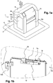
- the figure 1a is a perspective view of a container equipped with a lockable hatch.
- container 1 is of the buried type. It comprises, in known manner, a buried tank 4 flush with the ground 2, and a terminal 6 waste introduction. Conventionally, the container 1 is provided with a gripping device 8 for lifting the container, in particular to ensure its regular emptying.
- the terminal 6 comprises a front face 6a on which opens an opening for introducing waste into the tank 4.
- the container 1 is dedicated to the collection of household waste and the introduction opening is accessible by means of a drum 10.
- the terminal 6 further comprises an additional hatch, serving in the example of inspection hatch and / or trap large bulky waste.
- This hatch is located in the example on a side face 6b of the terminal. It is formed of a hatch panel 12 articulated on the front face 6a, by means of hinges 12a, one of which is visible on the figure 1b .
- the panel 12 in the example of generally rectangular shape, is provided with a locking mechanism 14 comprising a key lock 14a, type "captive key".
- a key lock 14a type "captive key”.
- an authorized person, possessing a key is in the possibility of unlocking the hatch and opening it in order to access an opening of dimensions greater than those of the opening accessible in the drum 10.
- the lock 14a is disposed near the upper edge 12b of the panel 12, and also close to the edge 12c located opposite the pivot axis of the hinges 12a.
- the lock 14a constitutes the part visible from the outside of the locking mechanism 14 represented on the Figures 1a to 4d .
- said mechanism disposed on the inner face of the panel 12, is therefore invisible from the outside the container.
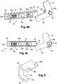
- the locking mechanism 14 shown on the figure 2a is viewed in perspective, the observation point being located on the inner side of the panel 12 (not shown), opposite the key introduction port.
- Said mechanism comprises a locking bolt 16, integral in rotation with an operating member, or driving cylinder (or barrel), of the lock 14a.
- the operation of the bolt is controlled by the lock 14a: when the lock is in the locked position, the bolt 16 is in a locking position which prevents the opening of the panel 12, and when the lock is in the unlocked position, the bolt 16 is in an unlocking position that allows the opening of the panel 12.
- the bolt joins one or other of these positions by a rotational movement about an axis XX coincides with the axis of rotation of the body of maneuver, or barrel, of the lock 14a.
- the bolt is in the unlocked position, it is retracted and no longer forms a projection from the edge 12b of the panel 12. It therefore allows the opening of the hatch.
- the bolt 16 has a generally parallelepiped shape. Its section in a plane perpendicular to the axis of rotation of the driving cylinder of the lock (axis XX on the figure 2a ) is of generally rectangular shape. In this case, the bolt 16 has an edge 16a forming a long side of length H and an edge 16b forming a short side of length L. In the example, the bolt is constituted by a thin plate. This plate is for example made of metal. The dimensions of the bolt 16, in particular its thickness, are of course compatible with the dimensions of the slot 7a.
- retaining means Near the bolt 16 are arranged retaining means. These means comprise a retaining element 18, mounted in translation on a support 20, the support 20 being fixed on the inner face of the panel 12, for example by means of screws passing through fixing holes 20a. A protective element 22 is fixed to the support 20 so as to form with it a housing containing the retaining means.
- the support 20 and the protection element 22 are two elongate elements with a "U" -shaped section. They are assembled mutually so as to form a housing within which the retaining element 18 slides.
- the protection element 22 is fixed to the support 20 by means of screws 23, cooperating with threaded studs 20b, visible in particular on the figure 2b , on which the protective element 22 is removed (for a better understanding, the protection element 22 is only shown on the figures 1b and 2a ).
- These pads are integral with the support 20 and projecting therefrom.
- the retaining element 18, also having a generally U-shaped section comprises two windows 18a, each window being crossed by one of the studs tapped 20b. The dimensions of each window 18a, in particular their dimension along the sliding axis of the retaining element 18, are such that they do not hinder the free movement of the retaining element 18.
- the retaining means also comprise elastic return means urging the retaining element 18 towards a locking position, this bias tending to bring the retaining element 18 closer to the axis of rotation of the drive cylinder of the lock 14a. , in a plane perpendicular to this axis.
- the elastic return means comprise a cylindrical compression spring 19 bearing at one of its ends on a threaded stud 20b of the support 20 and, at the opposite end, on the retaining element 18. So, as we can see on the Figure 2c the spring 19 tends to bring the retaining element 18 to the right of the figure.
- a stop finger 24 is also integral with the drive cylinder of the lock 14a.
- the stop finger is elongate in a direction perpendicular to the elongation direction of the bolt 16, and also perpendicular to the axis XX of rotation of the drive cylinder of the lock 14a.
- the stop finger 24 is of generally parallelepipedal shape and its section in a plane perpendicular to the axis of rotation of the drive cylinder of the lock 14a is of generally rectangular shape.
- the stop finger 24 has an edge 24a a long side of length D and an edge 24b forming a short side 24b of length E.
- the bolt 16 and the stop finger 24 are formed by a single piece in the shape of "L”, pierced with a fixing hole, and secured to the drive cylinder of the lock 14a to by means of a screw 26.
- An eccentric hole 26a forming a rotational stop element is also provided in the "L” shaped piece, in order to prevent any rotation of the bolt relative to the drive cylinder of the lock 14a. .
- the distance F between the axis of rotation XX and the distal edge 24b of the stop finger 24 is strictly greater than the distance G between the axis of rotation XX and the distal edge 16b of the bolt 16.
- the locking mechanism according to the invention also comprises means for activating the retaining means.
- These activation means comprise a support 28 which carries a visible tooth 30, in particular on the figure 5 .
- the tooth 30 has at its free end a beveled portion 32 forming an inclined ramp, extending towards the end embedded in the support 28 by a straight portion 34.
- the support 28 is fixed rigidly to the edge 7 of the body 6 of the terminal of the container, and has for this purpose fixing holes 28a.
- the inclined ramp 32 is intended to cooperate with the retaining element 18, through a slot 22a formed on the protective element 22.
- the light 22a has a shape and dimensions allowing the passage of the tooth 30.
- the mechanism is in the locked state.
- the bolt 16 is in the locking position and the retaining element 18 is in the unlocking position.
- the retaining element 18 is recessed: it is distant relative to the axis of rotation XX and is not likely, in this position, to hinder the movement of the stop finger 24 (and bolt 16), as visible on the Figures 2b and 2c .
- the retaining element 18 In the locked state, the retaining element 18 is held in its unblocking position by the tooth 30 which, through the slot 22a of the closure element 22, presses, via the straight portion 34 , on a bearing surface of the retaining element 18.
- This bearing surface is constituted in the example by a tongue 18b, which is elongate in a direction perpendicular to the translation axis of the retaining element 18, or is slightly inclined with respect to this direction.
- a clear space is formed opposite the tongue 18b, in the example by a window 18c formed in the retaining element, to allow the housing of the tooth 30.
- the force generated by the support of the tooth 30 on the tongue 18b is substantially of the same direction as the force applied by the spring 19, but of opposite direction.
- the tongue 18b also serves to support the spring 19, the latter bearing on one side of the tongue located on the opposite side to the bearing surface of the tooth 30.
- FIGS. 3a and 3b show the mechanism being unlocked.
- the hatch is still closed, but a key has been inserted in the lock 14a to cause the bolt 16 to rotate.
- the retaining element 18 does not prevent rotation of the stop pin 24. and therefore of the bolt 16.
- the unlocked position of the lock 14a which requires in the example a rotation of about 90 °, the bolt 16 is in its unlocked position, and it is now possible to open the hatch.
- the retaining element remains in the unlocking position, under the action of the tooth 30, as long as the hatch is not open.
- FIGS. 4a to 4c show the locking mechanism when the hatch is open.
- the opening of the hatch causes the edge 12b of the panel 12 of the edge 7 to move away from each other.
- This distance has the consequence that the tooth 30, fixed relative to the body of the terminal, stops pressing the tab 18b of the retaining element 18.
- the retaining element 18 is then subject only to the force of the elastic return means (the spring 19), which push the retaining element 18 to its position. blocking, as can be seen by comparison of figures 3a and 4b .
- the retaining element when opening the hatch, the retaining element is moved from its unlocking position to its locking position, by a translational movement direction perpendicular to the axis XX.
- These two positions are determined so that the retaining element 18 constitutes an obstacle to the rotation of the stop finger 24 (as visible on the Figures 4b and 4c ) when the retaining element is in the locking position, and it does not oppose the passage of the stop finger 24 when in the unlocking position (as visible on the figures 2b and 3b ).
- the unlocking position is imposed by the tooth 30, as visible in particular on the figure 3b
- the locking position is imposed by the threaded studs 20b which form stops of the retaining element 18, as visible on the figure 4a to 4c .
- the blocking position must further allow the passage of the bolt 16 while prohibiting the passage of the stop finger 24, as visible on the Figures 4b and 4c .
- the amplitude of the translational movement of the retaining element 18 is less than the difference between, on the one hand, the distance F between the axis of rotation XX and the edge 24b distal of the stop finger 24 and, on the other hand, the distance G between the axis of rotation XX and the distal edge 16b of the bolt 16.
- the opening of the trap automatically forces the retaining element to take its blocking position.
- the retaining element is opposed to the passage of the stop finger if one tries to drive the lock 14a to its initial position, which therefore prevents any removal of the key.
- the tooth 30 presses again on the tongue 18b of the retaining element 18 via the inclined ramp 32, which acts on said tongue 18b like a cam by pushing the retaining element 18 to its end. unlocking position.
- the retaining element 18 then stops the finger from returning to its initial position, corresponding to the locking position of the lock shown on the Figures 2a to 2c .
- the invention thus achieves its objective by preventing any premature removal of the key when a user manipulates the hatch: removal of the key is possible only if the hatch is in the closed position. As soon as it is no longer in the closed position, any removal of the key automatically becomes impossible.
- This objective is further achieved by the arrangement of mechanical parts that are not very complex and therefore inexpensive and reliable. The invention is therefore particularly convenient to manufacture, to install on an existing hatch and to use.
- the invention is particularly reliable and suitable for the field of voluntary containers, or any other outdoor system to have a long life while requiring almost no maintenance.
- the invention finds an advantageous application in the field of voluntary delivery containers, application which is the subject of the example given above. However, it is clear that the invention finds application in all areas where it is necessary to provide the locking of a door or hatch.
Landscapes
- Engineering & Computer Science (AREA)
- Mechanical Engineering (AREA)
- Structural Engineering (AREA)
- Refuse Receptacles (AREA)
- Lock And Its Accessories (AREA)
Abstract
L'invention se rapporte à un mécanisme de verrouillage (14) d'une trappe (12) dans une position fermée, position dans laquelle ladite trappe obture une ouverture, le mécanisme de verrouillage comportant : - une serrure à clé (14a) apte à prendre deux positions distinctes, une position verrouillée, dans laquelle un pêne (16) s'oppose à l'ouverture de la trappe, et une position déverrouillée, dans laquelle le pêne (16) autorise l'ouverture de la trappe, la serrure (14) étant telle qu'elle n'autorise le retrait de la clé que dans la position verrouillée; - des moyens de retenue (18, 19) aptes à empêcher la serrure (14a) de revenir à la position verrouillée, des moyens d'activation (30, 32) des moyens de retenue (18, 19), aptes à activer les moyens de retenue lors de l'ouverture de la trappe et à désactiver les moyens de retenue lorsque la trappe est en position fermée. L'invention concerne également un conteneur d'apport volontaire pour la collecte de déchets dont une trappe est verrouillable au moyen d'un tel mécanisme.The invention relates to a locking mechanism (14) of a hatch (12) in a closed position, in which position said hatch closes an opening, the locking mechanism comprising: - A key lock (14a) adapted to take two distinct positions, a locked position, in which a bolt (16) opposes the opening of the door, and an unlocked position, in which the bolt (16) allows the opening of the hatch, the lock (14) being such that it allows the removal of the key only in the locked position; - retaining means (18, 19) adapted to prevent the lock (14a) from returning to the locked position, activation means (30, 32) of the retaining means (18, 19), able to activate the retaining means when the hatch is opened and to deactivate the retaining means when the hatch is in the closed position. The invention also relates to a voluntary intake container for the collection of waste, a hatch is lockable by means of such a mechanism.
Description
La présente invention est relative au domaine des mécanismes comportant une serrure permettant le verrouillage de tous types de trappes et de portes.The present invention relates to the field of mechanisms comprising a lock for locking all types of traps and doors.
La présente invention trouve une application avantageuse, mais en aucune manière exclusive, dans le domaine de la collecte de déchets au moyen de conteneurs d'apport volontaire.The present invention finds an advantageous, but in no way exclusive, application in the field of waste collection by means of voluntary delivery containers.
Les conteneurs d'apport volontaire sont des conteneurs installés sur la voie publique, à disposition des usagers qui peuvent ainsi y apporter leurs déchets triés et leurs ordures ménagères. Il est désormais usuel de collecter par ce biais des ordure ménagères et des déchets sélectionnés comme le verre, les emballages, le papier, etc.The containers of voluntary contribution are containers installed on the public road, at the disposal of the users who can thus bring their sorted waste there and their garbage. It is now customary to collect household waste and selected waste such as glass, packaging, paper and so on.
Les conteneurs d'apport volontaire sont généralement de trois types : aérien, enterré ou semi-enterré. Les deux dernières catégories regroupent des conteneurs dont la totalité ou la plus grande partie du volume de stockage est disposée sous terre, dans le but de minimiser l'encombrement de la voirie et l'impact visuel des conteneurs sur le paysage. Les conteneurs de type « aérien » sont simplement posés au sol et l'intégralité de leur volume de stockage se trouve hors sol.Voluntary containers are generally of three types: aerial, buried or semi-buried. The last two categories include containers where all or most of the storage volume is underground, with the aim of minimizing congestion and the visual impact of containers on the landscape. The "air" type containers are simply placed on the ground and all of their storage volume is above ground.
Un conteneur d'apport volontaire présente une ou plusieurs ouvertures de forme et de dimensions adaptées au type de déchet auquel le conteneur est dédié. Par exemple, pour un conteneur de collecte de verre, on prévoit un orifice de section circulaire de diamètre compatible avec les dimensions courantes des bouteilles de verre. Pour un conteneur de collecte de papier, on prévoit un orifice de section oblongue, de dimensions adaptées à l'introduction de journaux, magazines, etc. Pour un conteneur destiné à la collecte des ordures ménagères, on prévoit en général une ouverture accessible par un tambour, permettant de réaliser un sas de sécurité évitant la communication directe entre le volume de stockage et l'extérieur, lors de l'introduction de déchets.A voluntary intake container has one or more openings of shape and dimensions adapted to the type of waste to which the container is dedicated. For example, for a glass collection container, there is provided an orifice of circular section of diameter compatible with the current dimensions of the glass bottles. For a paper collection container, there is provided an oblong section orifice, sized for the introduction of newspapers, magazines, etc. For a container intended for garbage collection, provision is generally made for an opening accessible by a drum, making it possible to create a safety lock avoiding direct communication between the storage volume and the outside, during the introduction of refuse. .
Certains conteneurs sont pourvus, en plus de l'ouverture classique, d'une trappe additionnelle, servant de trappe de visite et/ou de trappe d'introduction de déchets volumineux. Une telle trappe présente généralement des dimensions plus grandes que l'ouverture principale, et est munie d'un moyen de verrouillage, par exemple une serrure à clé. En général, la trappe additionnelle se présente sous la forme d'un panneau articulé sur la borne, ce panneau étant parfois configuré de sorte qu'il porte l'ouverture principale. Une clé est en général confiée à des personnes autorisées, par exemple les agents d'entretien amenés à intervenir sur le conteneur ou des personnes appartenant à des entités productrices de quantités importantes de déchets (commerces, administrations, collectivités, etc.)Some containers are provided, in addition to the conventional opening, an additional hatch, serving as inspection hatch and / or trap large bulky waste. Such a hatch generally has larger dimensions than the main opening, and is provided with a locking means, for example a key lock. In general, the additional hatch is in the form of a panel articulated on the terminal, this panel being sometimes configured so that it carries the main opening. A key is generally entrusted to authorized persons, for example the maintenance agents who have to intervene on the container or persons belonging to entities producing large quantities of waste (businesses, administrations, communities, etc.).
Un moyen de verrouillage couramment utilisé est une serrure dite à clé captive, le plus souvent de type « quart de tour ». Ce système présente notamment l'avantage d'éviter à un usager de perdre la clé dont il dispose. En effet, pour introduire des déchets via la trappe, il est nécessaire d'introduire la clé dans la serrure, de faire pivoter celle-ci jusqu'au point de déverrouillage, puis d'ouvrir la trappe ainsi libérée. Dans cette configuration, la clé est prisonnière de la serrure et il est impossible de la retirer. Pour pouvoir retirer la clé, il est nécessaire de revenir à la position angulaire de verrouillage de la serrure, c'est-à-dire la position initiale d'introduction de la clé.A commonly used locking means is a so-called captive key lock, most often of the "quarter turn" type. This system has the particular advantage of preventing a user from losing the key he has. Indeed, to introduce waste via the hatch, it is necessary to introduce the key in the lock, to rotate it to the unlocking point, then open the hatch and released. In this configuration, the key is locked in the lock and can not be removed. To be able to remove the key, it is necessary to return to the angular locking position of the lock, that is to say the initial position of insertion of the key.
Dans le cadre d'un usage normal, on revient à cette position après avoir refermé la trappe. Toutefois, aucun dispositif de sécurité n'empêche de remettre la serrure en position de verrouillage et de retirer la clé alors que la trappe est toujours en position ouverte. Les inventeurs se sont ainsi aperçus qu'il était fréquent qu'un usager ouvre la trappe, puis, par commodité personnelle, récupère aussitôt sa clé avant d'introduire ses déchets, et abandonne ensuite la trappe ouverte. Le fait qu'une trappe puisse ainsi demeurer en position ouverte doit être absolument évité car cela représente un danger important : un enfant pourrait en effet se pencher au-dessus de l'orifice laissé libre par la trappe ouverte et basculer dans la cuve. En dehors de ce risque avéré, il n'est simplement pas souhaitable que les usagers puissent ainsi abandonner une trappe en position ouverte, car c'est contraire au bon usage d'un tel équipement collectif.In the normal use, it returns to this position after closing the hatch. However, no safety device prevents the lock from being put back in the locked position and the key removed while the hatch is still in the open position. The inventors thus realized that it was common for a user to open the hatch, then, for personal convenience, immediately retrieve his key before introducing his waste, and then abandon the open hatch. The fact that a hatch can thus remain in the open position must be absolutely avoided because it represents a significant danger: a child could indeed lean over the open port left by the open hatch and tilt into the tank. Apart from this proven risk, it is simply not desirable for users to be able to abandon a hatch in the open position, because it is contrary to the proper use of such collective equipment.
Au cours de leurs recherches visant à résoudre ce problème, les inventeurs ont constaté qu'il n'existait pas de solution adaptée qui soit simple et économique.In their research to solve this problem, the inventors have found that there is no suitable solution that is simple and economical.
La présente invention a pour objectif de pallier cette carence en proposant un mécanisme de verrouillage qui puisse équiper tous types de trappe fermant à clé, de manière à ce que la trappe ainsi équipée ne puisse en aucun cas être abandonnée en position ouverte. Dans la présente description, le terme trappe désigne aussi bien de petites ou grandes ouvertures, y compris des portes.The present invention aims to overcome this deficiency by providing a locking mechanism that can equip all types of lockable door, so that the hatch thus equipped can in no case be abandoned in the open position. In the present description, the term trap covers both small and large openings, including doors.
A cette fin, l'invention propose un mécanisme de verrouillage d'une trappe comportant une serrure qui ne peut revenir à sa position de verrouillage, et donc de retrait de la clé, seulement si la trappe est en position fermée.To this end, the invention provides a locking mechanism of a door having a lock that can return to its locking position, and therefore the removal of the key, only if the door is in the closed position.
Ainsi, l'invention concerne un mécanisme de verrouillage d'une trappe dans une position fermée, position dans laquelle ladite trappe obture une ouverture, le mécanisme de verrouillage comportant :
- une serrure à clé apte à prendre deux positions distinctes, une position verrouillée, dans laquelle un pêne s'oppose à l'ouverture de la trappe, et une position déverrouillée, dans laquelle le pêne autorise l'ouverture de la trappe, la serrure étant telle qu'elle n'autorise le retrait de la clé que dans la position verrouillée ;
- des moyens de retenue aptes à empêcher la serrure de revenir à la position verrouillée,
- des moyens d'activation des moyens de retenue, aptes à activer les moyens de retenue lors de l'ouverture de la trappe et à désactiver les moyens de retenue lorsque la trappe est en position fermée.
- a key lock adapted to take two distinct positions, a locked position, in which a bolt opposes the opening of the hatch, and an unlocked position, in which the bolt authorizes the opening of the hatch, the lock being such that it authorizes the removal of the key only in the position locked;
- retaining means adapted to prevent the lock from returning to the locked position,
- means for activating the retaining means, able to activate the retaining means when the hatch is opened and to deactivate the retaining means when the hatch is in the closed position.
L'objectif de l'invention est atteint grâce aux moyens de retenue activés par les moyens d'activation lors de l'ouverture de la trappe, et désactivés par ces mêmes moyens lors de la fermeture de celle-ci. Lorsqu'ils sont activés, c'est-à-dire dès que la trappe est ouverte et tant qu'elle n'est pas refermée, les moyens de retenue empêchent tout mouvement de la serrure tendant à ramener celle-ci vers sa position de verrouillage. Ainsi, grâce à l'invention, il n'existe qu'une seule et unique position de la trappe dans laquelle il est permis d'introduire ou de retirer une clé : la position fermée.The object of the invention is achieved thanks to the retaining means activated by the activation means during the opening of the hatch, and deactivated by these same means when closing thereof. When they are activated, that is to say as soon as the hatch is open and until it is closed, the retaining means prevent any movement of the lock tending to bring it back to its position of locking. Thus, thanks to the invention, there is only one and only position of the hatch in which it is allowed to introduce or remove a key: the closed position.
Le mécanisme selon l'invention peut également présenter l'une ou plusieurs des caractéristiques suivantes :
- les moyens de retenue comportent :
- un élément de retenue, mobile entre une position de blocage dans laquelle il empêche le retour de la serrure à la position verrouillée et une position de déblocage dans laquelle il autorise ce retour;
- des moyens de rappel élastique, sollicitant l'élément de retenue vers sa position de blocage ;
- les moyens d'activation comprennent une dent, solidaire d'un encadrement de l'ouverture, dont une portion forme une rampe inclinée apte à entraîner l'élément de retenue pour le déplacer vers sa position de déblocage lorsque la trappe est en position fermée ;
- l'élément de retenue comporte une surface d'appui apte à coopérer avec la rampe inclinée ;
- l'élément de retenue est mobile en translation entre sa position de blocage et sa position de déblocage ;
- les moyens de rappel élastique comportent un ressort, tel qu'un ressort cylindrique de compression ;
- l'élément de retenue s'oppose à la rotation de la serrure lorsque l'élément de retenue est en position de blocage en formant obstacle au mouvement d'un doigt d'arrêt solidaire en rotation d'un organe de rotatif de la serrure ;
- le doigt d'arrêt vient de matière avec le pêne ;
- le pêne a un mouvement rotatif lors du mouvement de la serrure entre deux positions ;
- la serrure est une serrure de type « quart de tour ».
- the retaining means comprise:
- a retaining element movable between a locking position in which it prevents the return of the lock to the locked position and an unlocking position in which it authorizes this return;
- elastic return means urging the retaining element towards its locking position;
- the activation means comprise a tooth, integral with a frame of the opening, a portion of which forms an inclined ramp capable of driving the retaining element to move it towards its unlocking position when the hatch is in the closed position;
- the retaining element comprises a bearing surface capable of cooperating with the inclined ramp;
- the retaining element is movable in translation between its locking position and its unlocking position;
- the elastic return means comprise a spring, such as a cylindrical compression spring;
- the retaining element opposes the rotation of the lock when the retaining element is in the blocking position by forming an obstacle to the movement of a stop finger integral in rotation with a rotary member of the lock;
- the stop finger comes from material with the bolt;
- the bolt has a rotary movement when the lock moves between two positions;
- the lock is a quarter turn lock.
L'invention concerne également un conteneur d'apport volontaire pour la collecte de déchets, comportant une trappe munie d'un mécanisme de verrouillage tel que défini ci-dessus.The invention also relates to a voluntary intake container for the collection of waste, comprising a hatch provided with a locking mechanism as defined above.
Dans une réalisation, le conteneur d'apport volontaire est équipé d'un mécanisme de verrouillage dont les moyens d'activation comportent une dent telle que définie plus haut, le conteneur comportant un corps duquel est solidaire ladite dent.In one embodiment, the voluntary intake container is equipped with a locking mechanism whose activation means comprise a tooth as defined above, the container having a body which is secured to said tooth.
La trappe du conteneur peut être montée pivotante ou coulissante sur le corps du conteneur.The container hatch can be pivotally or slidably mounted on the container body.
Une ouverture de collecte des déchets peut être ménagée dans la trappe. L'invention sera mieux comprise à la lecture de la description qui va suivre, donnée uniquement à titre d'exemple et faite en se référant aux figures annexées, parmi lesquelles :
- la
figure 1a est une vue générale d'un conteneur d'apport volontaire enterré, dont une trappe est équipée d'un mécanisme de verrouillage conforme à l'invention; - la
figure 1b est une vue partielle de l'intérieur du conteneur de lafigure 1a , montrant plus particulièrement le mécanisme de verrouillage ; - les
figure 2a et 2b représentent un mécanisme de verrouillage d'une trappe conforme à l'invention, vu en perspective, en position verrouillée, un élément de protection du mécanisme étant retiré sur lafigure 2b ; - la
figure 2c est une vue en élévation verticale du mécanisme de lafigure 1b ; - la
figure 3a est une vue en perspective du mécanisme en cours de déverrouillage ; - la
figure 3b est vue en une élévation verticale du mécanisme dans un état analogue à lafigure 3a ; - la
figure 4a est une vue en élévation du mécanisme déverrouillé ; - les
figures 4b et 4c sont des vues en perspective du mécanisme déverrouillé ; - la
figure 5 est une vue en perspective d'un exemple de réalisation des moyens d'activation selon l'invention.
- the
figure 1a is a general view of a buried voluntary intake container, a hatch is equipped with a locking mechanism according to the invention; - the
figure 1b is a partial view of the inside of the container from thefigure 1a , showing more particularly the locking mechanism; - the
Figure 2a and 2b represent a locking mechanism of a hatch according to the invention, seen in perspective, in the locked position, a protection element of the mechanism being removed on thefigure 2b ; - the
Figure 2c is a vertical elevation view of the mechanism of thefigure 1b ; - the
figure 3a is a perspective view of the mechanism being unlocked; - the
figure 3b is seen in a vertical elevation of the mechanism in a state analogous tofigure 3a ; - the
figure 4a is an elevational view of the unlocked mechanism; - the
Figures 4b and 4c are perspective views of the unlocked mechanism; - the
figure 5 is a perspective view of an exemplary embodiment of the activation means according to the invention.
La
Dans l'exemple de la
La borne 6 comporte en outre une trappe additionnelle, servant dans l'exemple de trappe de visite et/ou de trappe d'introduction de déchets volumineux. Cette trappe est située dans l'exemple sur une face latérale 6b de la borne. Elle est formée d'un panneau de trappe 12 articulé sur la face avant 6a, au moyens de charnières 12a, dont une est visible sur la
La serrure 14a constitue la partie visible depuis l'extérieur du mécanisme de verrouillage 14 représenté sur les
Le mécanisme de verrouillage 14 représenté sur la
Dans un plan perpendiculaire à l'axe XX, la forme et les dimensions du pêne 16 sont telles que :
- lorsqu'il est en position de verrouillage, le pêne 16 est allongé selon une direction sensiblement perpendiculaire au bord 12b du panneau 12, de manière à présenter une partie en saillie depuis le bord 12b, en direction d'un bord 7 (
figure 1 b) ducorps 6 de la borne du conteneur situé en vis-à-vis du bord 12b, le bord 7 formant une partie de l'encadrement du panneau 12. Dans ladite position de verrouillage, une portion du pêne 16 est insérée dans une fente 7a ménagée sur le bord 7 ; - lorsqu'il est en position de déverrouillage, il ne forme pas de partie en saillie depuis le bord 12b du panneau 12.
- when in the locking position, the
bolt 16 is elongated in a direction substantially perpendicular to theedge 12b of thepanel 12, so as to have a portion projecting from theedge 12b, towards an edge 7 (Figure 1 (b) of thebody 6 of the terminal of the container located opposite theedge 12b, theedge 7 forming a portion of the frame of thepanel 12. In said locking position, a portion of thebolt 16 is inserted into aslot 7a arranged on theedge 7; - when it is in the unlocking position, it does not form a protruding portion from the
edge 12b of thepanel 12.
Ainsi, en position de verrouillage, la portion du pêne 16 qui est insérée dans la fente 7a du bord 7, interdit l'ouverture de la trappe. Lorsque le pêne est en position de déverrouillage, il est escamoté et ne forme plus une saillie depuis le bord 12b du panneau 12. Il autorise donc l'ouverture de la trappe.Thus, in the locking position, the portion of the
Dans l'exemple, le pêne 16 a une forme globalement parallélépipédique. Sa section dans un plan perpendiculaire à l'axe de rotation du cylindre d'entrainement de la serrure (axe XX sur la
A proximité du pêne 16 sont disposés des moyens de retenue. Ces moyens comportent un élément de retenue 18, monté à translation sur un support 20, le support 20 étant fixé sur la face interne du panneau 12, par exemple au moyen de vis traversant des trous de fixation 20a. Un élément de protection 22 est fixé au support 20 de sorte à former avec lui un boîtier contenant les moyens de retenue.Near the
Dans l'exemple, le support 20 et l'élément de protection 22 sont deux éléments allongés à section en forme de « U ». Ils sont assemblés mutuellement de manière à former un boîtier à l'intérieur duquel coulisse l'élément de retenue 18. L'élément de protection 22 est fixé au support 20 au moyen de vis 23, coopérant avec des plots taraudés 20b, visibles notamment sur la
Les moyens de retenue comportent également des moyens de rappel élastique sollicitant l'élément de retenue 18 vers une position de blocage, cette sollicitation tendant à rapprocher l'élément de retenue 18 de l'axe de rotation du cylindre d'entraînement de la serrure 14a, dans un plan perpendiculaire à cet axe. Dans l'exemple, les moyens de rappel élastique comportent un ressort cylindrique de compression 19 prenant appui à l'une de ses extrémités sur un plot taraudé 20b du support 20 et, à l'extrémité opposée, sur l'élément de retenue 18. Ainsi, comme on peut l'observer sur la
Un doigt d'arrêt 24 est également solidaire du cylindre d'entrainement de la serrure 14a. Dans l'exemple, le doigt d'arrêt est allongé selon une direction perpendiculaire à la direction d'allongement du pêne 16, et également perpendiculaire à l'axe XX de rotation du cylindre d'entrainement de la serrure 14a. Dans l'exemple, le doigt d'arrêt 24 est de forme globalement parallélépipédique et sa section dans un plan perpendiculaire à l'axe de rotation du cylindre d'entrainement de la serrure 14a est de forme globalement rectangulaire. Comme visible plus particulièrement sur la
Dans le présent exemple de réalisation, le pêne 16 et le doigt d'arrêt 24 sont formés par une pièce unique en forme de « L », percée d'un trou de fixation, et solidarisée au cylindre d'entrainement de la serrure 14a au moyen d'une vis 26. Un trou 26a excentré formant un élément d'arrêt en rotation est également prévu dans la pièce en forme de « L », afin de prévenir toute rotation du pêne par rapport au cylindre d'entrainement de la serrure 14a.In the present embodiment, the
La distance F entre l'axe de rotation XX et le bord 24b distal du doigt d'arrêt 24 est strictement supérieure à la distance G entre l'axe de rotation XX et le bord 16b distal du pêne 16.The distance F between the axis of rotation XX and the
Le mécanisme de verrouillage conforme à l'invention comporte également des moyens d'activation des moyens de retenue. Ces moyens d'activation comportent un support 28 qui porte une dent 30 visible notamment sur la
La rampe inclinée 32 est destinée à venir coopérer avec l'élément de retenue 18, à travers une lumière 22a ménagée sur l'élément de protection 22. La lumière 22a présente une forme et des dimensions autorisant le passage de la dent 30.The
Sur les
A l'état verrouillé, l'élément de retenue 18 est maintenu dans sa position de déblocage par la dent 30 qui, au travers de la lumière 22a de l'élément de fermeture 22, appuie, par l'intermédiaire de la portion droite 34, sur une surface d'appui de l'élément de retenue 18. Cette surface d'appui est constituée dans l'exemple par une languette 18b, qui est allongée selon une direction perpendiculaire à l'axe de translation de l'élément de retenue 18, ou est faiblement inclinée par rapport à cette direction. Un espace dégagé est formé en regard de la languette 18b, dans l'exemple par une fenêtre 18c ménagée dans l'élément de retenue, pour permettre le logement de la dent 30. L'effort généré par l'appui de la dent 30 sur la languette 18b est sensiblement de même direction que l'effort appliqué par le ressort 19, mais de direction opposée. Il est à noter que, dans le présent exemple, la languette 18b sert également d'appui au ressort 19, ce dernier prenant appui sur une face de la languette située du côté opposé à la surface d'appui de la dent 30.In the locked state, the retaining
Les
Les
Ainsi, lors de l'ouverture de la trappe, l'élément de retenue est déplacé de sa position de déblocage vers sa position de blocage, par un mouvement de translation de direction perpendiculaire à l'axe XX. Ces deux positions sont déterminées de sorte que l'élément de retenue 18 constitue un obstacle à la rotation du doigt d'arrêt 24 (comme visible sur les
Dans l'exemple, comme le pêne 16 et le doigt d'arrêt 24 sont allongés selon des directions perpendiculaires, la position de blocage doit en outre permettre le passage du pêne 16 tout en interdisant le passage du doigt d'arrêt 24, comme visible sur les
Comme on peut l'observer notamment sur les
Si l'on souhaite retirer la clé, il est donc impératif de refermer préalablement la trappe. La dent 30 vient alors à nouveau appuyer sur la languette 18b de l'élément de retenue 18 par l'intermédiaire de la rampe inclinée 32, laquelle agit sur ladite languette 18b comme une came en repoussant l'élément de retenue 18 jusqu'à sa position de déblocage. L'élément de retenue 18 n'interdit alors plus au doigt de passage de revenir à sa position initiale, correspondant à la position de verrouillage de la serrure représentée sur les
L'invention atteint donc son objectif en empêchant tout retrait prématuré de la clé lorsqu'un utilisateur manipule la trappe : le retrait de la clé n'est possible que si la trappe est en position fermée. Dès que celle-ci n'est plus en position fermée, tout retrait de la clé devient automatiquement impossible. Cet objectif est en outre atteint par l'agencement de pièces mécaniques peu complexes, donc peu coûteuses et fiables. L'invention est donc particulièrement commode à fabriquer, à installer sur une trappe existante et à utiliser.The invention thus achieves its objective by preventing any premature removal of the key when a user manipulates the hatch: removal of the key is possible only if the hatch is in the closed position. As soon as it is no longer in the closed position, any removal of the key automatically becomes impossible. This objective is further achieved by the arrangement of mechanical parts that are not very complex and therefore inexpensive and reliable. The invention is therefore particularly convenient to manufacture, to install on an existing hatch and to use.
Au surplus, l'invention est particulièrement fiable et adaptée au domaine des conteneurs d'apport volontaire, ou de tout autre système d'extérieur devant présenter une durée de vie importante tout en requérant un entretien quasi nul.In addition, the invention is particularly reliable and suitable for the field of voluntary containers, or any other outdoor system to have a long life while requiring almost no maintenance.
L'invention trouve une application avantageuse dans le domaine des conteneurs d'apport volontaire, application qui fait l'objet de l'exemple donné ci-dessus. Toutefois, il est clair que l'invention trouve une application dans tous les domaines où il est nécessaire de prévoir le verrouillage d'une porte ou d'une trappe.The invention finds an advantageous application in the field of voluntary delivery containers, application which is the subject of the example given above. However, it is clear that the invention finds application in all areas where it is necessary to provide the locking of a door or hatch.
Claims (14)
Applications Claiming Priority (1)
| Application Number | Priority Date | Filing Date | Title |
|---|---|---|---|
| FR1151622A FR2972018B1 (en) | 2011-02-28 | 2011-02-28 | LATCH LATCH MECHANISM AND WASTE COLLECTION CONTAINER HAVING A LOCKABLE TRAPPER USING SUCH A MECHANISM |
Publications (2)
| Publication Number | Publication Date |
|---|---|
| EP2492422A1 true EP2492422A1 (en) | 2012-08-29 |
| EP2492422B1 EP2492422B1 (en) | 2016-12-28 |
Family
ID=45688387
Family Applications (1)
| Application Number | Title | Priority Date | Filing Date |
|---|---|---|---|
| EP12157390.1A Active EP2492422B1 (en) | 2011-02-28 | 2012-02-28 | Mechanism for locking a hatch and waste-collection container provided with a hatch that can be locked by means of such a mechanism |
Country Status (2)
| Country | Link |
|---|---|
| EP (1) | EP2492422B1 (en) |
| FR (1) | FR2972018B1 (en) |
Cited By (1)
| Publication number | Priority date | Publication date | Assignee | Title |
|---|---|---|---|---|
| CN115045568A (en) * | 2022-05-24 | 2022-09-13 | 杭州齐丰科技有限公司 | Automatic door lock structure of bottle washing machine |
Families Citing this family (1)
| Publication number | Priority date | Publication date | Assignee | Title |
|---|---|---|---|---|
| CN110077765A (en) * | 2019-04-23 | 2019-08-02 | 成都市云海天环保科技有限公司 | A kind of multi-functional feeding tank |
Citations (5)
| Publication number | Priority date | Publication date | Assignee | Title |
|---|---|---|---|---|
| DE144512C (en) * | ||||
| FR2749569A1 (en) * | 1996-06-07 | 1997-12-12 | Stasiak Michel | Secure collection unit for e.g. hypodermic needles and syringes preventing danger of infection |
| US6658903B1 (en) * | 2000-09-27 | 2003-12-09 | Mcshane James P. | Thermally insulated lock box and lock therefor |
| US20040160130A1 (en) * | 2003-01-21 | 2004-08-19 | Eckerdt George H. | Door key retention security system |
| FR2913962A1 (en) * | 2007-03-20 | 2008-09-26 | Multi Com Affichage Sarl | Street furniture e.g. container, for collecting e.g. plastic cap, has structure delimiting chute/slope that is prolonged in its lower part by evacuation tube, where tube emerges on opening accessible from exterior by gate |
-
2011
- 2011-02-28 FR FR1151622A patent/FR2972018B1/en active Active
-
2012
- 2012-02-28 EP EP12157390.1A patent/EP2492422B1/en active Active
Patent Citations (5)
| Publication number | Priority date | Publication date | Assignee | Title |
|---|---|---|---|---|
| DE144512C (en) * | ||||
| FR2749569A1 (en) * | 1996-06-07 | 1997-12-12 | Stasiak Michel | Secure collection unit for e.g. hypodermic needles and syringes preventing danger of infection |
| US6658903B1 (en) * | 2000-09-27 | 2003-12-09 | Mcshane James P. | Thermally insulated lock box and lock therefor |
| US20040160130A1 (en) * | 2003-01-21 | 2004-08-19 | Eckerdt George H. | Door key retention security system |
| FR2913962A1 (en) * | 2007-03-20 | 2008-09-26 | Multi Com Affichage Sarl | Street furniture e.g. container, for collecting e.g. plastic cap, has structure delimiting chute/slope that is prolonged in its lower part by evacuation tube, where tube emerges on opening accessible from exterior by gate |
Cited By (1)
| Publication number | Priority date | Publication date | Assignee | Title |
|---|---|---|---|---|
| CN115045568A (en) * | 2022-05-24 | 2022-09-13 | 杭州齐丰科技有限公司 | Automatic door lock structure of bottle washing machine |
Also Published As
| Publication number | Publication date |
|---|---|
| EP2492422B1 (en) | 2016-12-28 |
| FR2972018B1 (en) | 2014-03-14 |
| FR2972018A1 (en) | 2012-08-31 |
Similar Documents
| Publication | Publication Date | Title |
|---|---|---|
| EP4003866B1 (en) | Safety cap | |
| EP1941821A1 (en) | Dispenser with rollers arranged side by side and equipped with a bottom sliding trapdoor | |
| CA2348711A1 (en) | Device for locking/unlocking, by gravity, the lid of a container and container equipped therewith | |
| FR2762306A1 (en) | DEVICE FOR LOCKING THE COVER OF A TRAY AND TRAY THEREOF | |
| WO2004067399A1 (en) | Closure cap for a bottle with controlled opening | |
| FR2790784A1 (en) | SECURITY DEVICE FOR A DOOR FOR PREVENTING THE FINGER OF THE FINGERS ON THE HINGES SIDE | |
| EP1882779A1 (en) | Locking and unlocking device using a key for a stamp or a cover on a frame, in particular of a manhole cover | |
| EP2492422B1 (en) | Mechanism for locking a hatch and waste-collection container provided with a hatch that can be locked by means of such a mechanism | |
| FR3016652A1 (en) | INVIOLABLE LOCKING AND UNLOCKING DEVICE WITH REMOVABLE KEY FOR OPENING | |
| FR2957109A1 (en) | LATCHING / UNLOCKING DEVICE WITH IMPROVED INVIOLABILITY AND ITS BUFFER KEY AND OPENING FOUNDRY PART | |
| EP1854942B1 (en) | Device for restricting access to the lock of a locking mechanism, in particular of a swing gate | |
| FR3068062A1 (en) | LOCKING DEVICE | |
| FR2914001A1 (en) | Casement locking system for closing opening in wall, has security device comprising part integrated to web and another part mounted in translation on handle along sliding axis perpendicular to another axis | |
| FR2871509A1 (en) | Protective barrier gate for swimming pool, has operating button that is actuated to lift interlocking rod and to pull out stop pin from fixed interlocking wedge for unlocking gate, where rod is mounted vertically at gate end | |
| BE1017308A5 (en) | LOCK. | |
| EP3530851B1 (en) | Locking system for a sectional door with lateral movement | |
| FR2934300A1 (en) | Opening frame e.g. window, half-opening device, has retaining passageway with clearance authorizing pivoting movement of spacing unit along spacing degree with respect to plane in which spacing unit is extended in unstressed position | |
| EP0621048A1 (en) | Box for contaminated medical articles | |
| EP4108856B1 (en) | Device for controlling a system for locking/unlocking a door leaf, and joinery comprising same | |
| FR2907477A1 (en) | Road device for forming manhole, has bolt with end part cooperating with striker to prevent tilting of stopper from security position to closing position when stopper is moved from closing position to open position | |
| EP1396446A1 (en) | Device for locking/unlocking the lid of a refuse receptacle | |
| FR2966136A1 (en) | Container for collecting half-buried household waste, has locking system holding lid in opening position when actuation element is in one of positions, and restoring elements restoring actuation element in another position | |
| FR2629510A1 (en) | Wind stop for leaves of shutters of doors, French doors (patio doors), windows or the like | |
| EP4481139A1 (en) | Pool cover lock | |
| FR2963634A1 (en) | Door lock, has movable locking member placed laterally to locking groove and adapted to engage with protection plate, where locking member is designed to block groove in translation when plate pivots around pivoting axle |
Legal Events
| Date | Code | Title | Description |
|---|---|---|---|
| PUAI | Public reference made under article 153(3) epc to a published international application that has entered the european phase |
Free format text: ORIGINAL CODE: 0009012 |
|
| AK | Designated contracting states |
Kind code of ref document: A1 Designated state(s): AL AT BE BG CH CY CZ DE DK EE ES FI FR GB GR HR HU IE IS IT LI LT LU LV MC MK MT NL NO PL PT RO RS SE SI SK SM TR |
|
| AX | Request for extension of the european patent |
Extension state: BA ME |
|
| 17P | Request for examination filed |
Effective date: 20130228 |
|
| 17Q | First examination report despatched |
Effective date: 20130410 |
|
| GRAP | Despatch of communication of intention to grant a patent |
Free format text: ORIGINAL CODE: EPIDOSNIGR1 |
|
| INTG | Intention to grant announced |
Effective date: 20160712 |
|
| GRAS | Grant fee paid |
Free format text: ORIGINAL CODE: EPIDOSNIGR3 |
|
| GRAA | (expected) grant |
Free format text: ORIGINAL CODE: 0009210 |
|
| AK | Designated contracting states |
Kind code of ref document: B1 Designated state(s): AL AT BE BG CH CY CZ DE DK EE ES FI FR GB GR HR HU IE IS IT LI LT LU LV MC MK MT NL NO PL PT RO RS SE SI SK SM TR |
|
| REG | Reference to a national code |
Ref country code: GB Ref legal event code: FG4D Free format text: NOT ENGLISH |
|
| REG | Reference to a national code |
Ref country code: CH Ref legal event code: EP |
|
| REG | Reference to a national code |
Ref country code: AT Ref legal event code: REF Ref document number: 857444 Country of ref document: AT Kind code of ref document: T Effective date: 20170115 |
|
| REG | Reference to a national code |
Ref country code: IE Ref legal event code: FG4D Free format text: LANGUAGE OF EP DOCUMENT: FRENCH |
|
| REG | Reference to a national code |
Ref country code: DE Ref legal event code: R096 Ref document number: 602012027012 Country of ref document: DE |
|
| REG | Reference to a national code |
Ref country code: FR Ref legal event code: PLFP Year of fee payment: 6 |
|
| PG25 | Lapsed in a contracting state [announced via postgrant information from national office to epo] |
Ref country code: LV Free format text: LAPSE BECAUSE OF FAILURE TO SUBMIT A TRANSLATION OF THE DESCRIPTION OR TO PAY THE FEE WITHIN THE PRESCRIBED TIME-LIMIT Effective date: 20161228 |
|
| REG | Reference to a national code |
Ref country code: NL Ref legal event code: FP |
|
| REG | Reference to a national code |
Ref country code: LT Ref legal event code: MG4D |
|
| PG25 | Lapsed in a contracting state [announced via postgrant information from national office to epo] |
Ref country code: NO Free format text: LAPSE BECAUSE OF FAILURE TO SUBMIT A TRANSLATION OF THE DESCRIPTION OR TO PAY THE FEE WITHIN THE PRESCRIBED TIME-LIMIT Effective date: 20170328 Ref country code: GR Free format text: LAPSE BECAUSE OF FAILURE TO SUBMIT A TRANSLATION OF THE DESCRIPTION OR TO PAY THE FEE WITHIN THE PRESCRIBED TIME-LIMIT Effective date: 20170329 Ref country code: SE Free format text: LAPSE BECAUSE OF FAILURE TO SUBMIT A TRANSLATION OF THE DESCRIPTION OR TO PAY THE FEE WITHIN THE PRESCRIBED TIME-LIMIT Effective date: 20161228 Ref country code: LT Free format text: LAPSE BECAUSE OF FAILURE TO SUBMIT A TRANSLATION OF THE DESCRIPTION OR TO PAY THE FEE WITHIN THE PRESCRIBED TIME-LIMIT Effective date: 20161228 |
|
| REG | Reference to a national code |
Ref country code: AT Ref legal event code: MK05 Ref document number: 857444 Country of ref document: AT Kind code of ref document: T Effective date: 20161228 |
|
| PG25 | Lapsed in a contracting state [announced via postgrant information from national office to epo] |
Ref country code: FI Free format text: LAPSE BECAUSE OF FAILURE TO SUBMIT A TRANSLATION OF THE DESCRIPTION OR TO PAY THE FEE WITHIN THE PRESCRIBED TIME-LIMIT Effective date: 20161228 Ref country code: BE Free format text: LAPSE BECAUSE OF NON-PAYMENT OF DUE FEES Effective date: 20170228 Ref country code: HR Free format text: LAPSE BECAUSE OF FAILURE TO SUBMIT A TRANSLATION OF THE DESCRIPTION OR TO PAY THE FEE WITHIN THE PRESCRIBED TIME-LIMIT Effective date: 20161228 Ref country code: RS Free format text: LAPSE BECAUSE OF FAILURE TO SUBMIT A TRANSLATION OF THE DESCRIPTION OR TO PAY THE FEE WITHIN THE PRESCRIBED TIME-LIMIT Effective date: 20161228 |
|
| PG25 | Lapsed in a contracting state [announced via postgrant information from national office to epo] |
Ref country code: SK Free format text: LAPSE BECAUSE OF FAILURE TO SUBMIT A TRANSLATION OF THE DESCRIPTION OR TO PAY THE FEE WITHIN THE PRESCRIBED TIME-LIMIT Effective date: 20161228 Ref country code: EE Free format text: LAPSE BECAUSE OF FAILURE TO SUBMIT A TRANSLATION OF THE DESCRIPTION OR TO PAY THE FEE WITHIN THE PRESCRIBED TIME-LIMIT Effective date: 20161228 Ref country code: IS Free format text: LAPSE BECAUSE OF FAILURE TO SUBMIT A TRANSLATION OF THE DESCRIPTION OR TO PAY THE FEE WITHIN THE PRESCRIBED TIME-LIMIT Effective date: 20170428 Ref country code: CZ Free format text: LAPSE BECAUSE OF FAILURE TO SUBMIT A TRANSLATION OF THE DESCRIPTION OR TO PAY THE FEE WITHIN THE PRESCRIBED TIME-LIMIT Effective date: 20161228 Ref country code: RO Free format text: LAPSE BECAUSE OF FAILURE TO SUBMIT A TRANSLATION OF THE DESCRIPTION OR TO PAY THE FEE WITHIN THE PRESCRIBED TIME-LIMIT Effective date: 20161228 |
|
| PG25 | Lapsed in a contracting state [announced via postgrant information from national office to epo] |
Ref country code: PT Free format text: LAPSE BECAUSE OF FAILURE TO SUBMIT A TRANSLATION OF THE DESCRIPTION OR TO PAY THE FEE WITHIN THE PRESCRIBED TIME-LIMIT Effective date: 20170428 Ref country code: PL Free format text: LAPSE BECAUSE OF FAILURE TO SUBMIT A TRANSLATION OF THE DESCRIPTION OR TO PAY THE FEE WITHIN THE PRESCRIBED TIME-LIMIT Effective date: 20161228 Ref country code: SM Free format text: LAPSE BECAUSE OF FAILURE TO SUBMIT A TRANSLATION OF THE DESCRIPTION OR TO PAY THE FEE WITHIN THE PRESCRIBED TIME-LIMIT Effective date: 20161228 Ref country code: BG Free format text: LAPSE BECAUSE OF FAILURE TO SUBMIT A TRANSLATION OF THE DESCRIPTION OR TO PAY THE FEE WITHIN THE PRESCRIBED TIME-LIMIT Effective date: 20170328 Ref country code: AT Free format text: LAPSE BECAUSE OF FAILURE TO SUBMIT A TRANSLATION OF THE DESCRIPTION OR TO PAY THE FEE WITHIN THE PRESCRIBED TIME-LIMIT Effective date: 20161228 Ref country code: IT Free format text: LAPSE BECAUSE OF FAILURE TO SUBMIT A TRANSLATION OF THE DESCRIPTION OR TO PAY THE FEE WITHIN THE PRESCRIBED TIME-LIMIT Effective date: 20161228 Ref country code: ES Free format text: LAPSE BECAUSE OF FAILURE TO SUBMIT A TRANSLATION OF THE DESCRIPTION OR TO PAY THE FEE WITHIN THE PRESCRIBED TIME-LIMIT Effective date: 20161228 |
|
| PG25 | Lapsed in a contracting state [announced via postgrant information from national office to epo] |
Ref country code: MC Free format text: LAPSE BECAUSE OF FAILURE TO SUBMIT A TRANSLATION OF THE DESCRIPTION OR TO PAY THE FEE WITHIN THE PRESCRIBED TIME-LIMIT Effective date: 20161228 |
|
| REG | Reference to a national code |
Ref country code: CH Ref legal event code: PL Ref country code: DE Ref legal event code: R097 Ref document number: 602012027012 Country of ref document: DE |
|
| PG25 | Lapsed in a contracting state [announced via postgrant information from national office to epo] |
Ref country code: CH Free format text: LAPSE BECAUSE OF NON-PAYMENT OF DUE FEES Effective date: 20170228 Ref country code: LI Free format text: LAPSE BECAUSE OF NON-PAYMENT OF DUE FEES Effective date: 20170228 |
|
| PLBE | No opposition filed within time limit |
Free format text: ORIGINAL CODE: 0009261 |
|
| STAA | Information on the status of an ep patent application or granted ep patent |
Free format text: STATUS: NO OPPOSITION FILED WITHIN TIME LIMIT |
|
| REG | Reference to a national code |
Ref country code: IE Ref legal event code: MM4A |
|
| PG25 | Lapsed in a contracting state [announced via postgrant information from national office to epo] |
Ref country code: DK Free format text: LAPSE BECAUSE OF FAILURE TO SUBMIT A TRANSLATION OF THE DESCRIPTION OR TO PAY THE FEE WITHIN THE PRESCRIBED TIME-LIMIT Effective date: 20161228 |
|
| 26N | No opposition filed |
Effective date: 20170929 |
|
| PG25 | Lapsed in a contracting state [announced via postgrant information from national office to epo] |
Ref country code: LU Free format text: LAPSE BECAUSE OF NON-PAYMENT OF DUE FEES Effective date: 20170228 |
|
| REG | Reference to a national code |
Ref country code: FR Ref legal event code: PLFP Year of fee payment: 7 |
|
| REG | Reference to a national code |
Ref country code: BE Ref legal event code: MM Effective date: 20170228 |
|
| PG25 | Lapsed in a contracting state [announced via postgrant information from national office to epo] |
Ref country code: IE Free format text: LAPSE BECAUSE OF NON-PAYMENT OF DUE FEES Effective date: 20170228 Ref country code: SI Free format text: LAPSE BECAUSE OF FAILURE TO SUBMIT A TRANSLATION OF THE DESCRIPTION OR TO PAY THE FEE WITHIN THE PRESCRIBED TIME-LIMIT Effective date: 20161228 |
|
| PG25 | Lapsed in a contracting state [announced via postgrant information from national office to epo] |
Ref country code: MT Free format text: LAPSE BECAUSE OF FAILURE TO SUBMIT A TRANSLATION OF THE DESCRIPTION OR TO PAY THE FEE WITHIN THE PRESCRIBED TIME-LIMIT Effective date: 20161228 |
|
| REG | Reference to a national code |
Ref country code: GB Ref legal event code: 732E Free format text: REGISTERED BETWEEN 20190110 AND 20190116 |
|
| REG | Reference to a national code |
Ref country code: DE Ref legal event code: R082 Ref document number: 602012027012 Country of ref document: DE Representative=s name: MAIWALD PATENTANWALTS- UND RECHTSANWALTSGESELL, DE Ref country code: DE Ref legal event code: R081 Ref document number: 602012027012 Country of ref document: DE Owner name: PLASTIC OMNIUM SYSTEMES URBAINS, FR Free format text: FORMER OWNER: COMPAGNIE PLASTIC OMNIUM, LYON, FR |
|
| REG | Reference to a national code |
Ref country code: NL Ref legal event code: PD Owner name: PLASTIC OMNIUM SYSTEMES URBAINS; FR Free format text: DETAILS ASSIGNMENT: CHANGE OF OWNER(S), ASSIGNMENT; FORMER OWNER NAME: COMPAGNIE PLASTIC OMNIUM Effective date: 20181228 |
|
| PG25 | Lapsed in a contracting state [announced via postgrant information from national office to epo] |
Ref country code: HU Free format text: LAPSE BECAUSE OF FAILURE TO SUBMIT A TRANSLATION OF THE DESCRIPTION OR TO PAY THE FEE WITHIN THE PRESCRIBED TIME-LIMIT; INVALID AB INITIO Effective date: 20120228 |
|
| PG25 | Lapsed in a contracting state [announced via postgrant information from national office to epo] |
Ref country code: CY Free format text: LAPSE BECAUSE OF NON-PAYMENT OF DUE FEES Effective date: 20161228 |
|
| PG25 | Lapsed in a contracting state [announced via postgrant information from national office to epo] |
Ref country code: MK Free format text: LAPSE BECAUSE OF FAILURE TO SUBMIT A TRANSLATION OF THE DESCRIPTION OR TO PAY THE FEE WITHIN THE PRESCRIBED TIME-LIMIT Effective date: 20161228 |
|
| PG25 | Lapsed in a contracting state [announced via postgrant information from national office to epo] |
Ref country code: TR Free format text: LAPSE BECAUSE OF FAILURE TO SUBMIT A TRANSLATION OF THE DESCRIPTION OR TO PAY THE FEE WITHIN THE PRESCRIBED TIME-LIMIT Effective date: 20161228 |
|
| PGFP | Annual fee paid to national office [announced via postgrant information from national office to epo] |
Ref country code: DE Payment date: 20200219 Year of fee payment: 9 Ref country code: GB Payment date: 20200219 Year of fee payment: 9 Ref country code: NL Payment date: 20200219 Year of fee payment: 9 |
|
| PG25 | Lapsed in a contracting state [announced via postgrant information from national office to epo] |
Ref country code: AL Free format text: LAPSE BECAUSE OF FAILURE TO SUBMIT A TRANSLATION OF THE DESCRIPTION OR TO PAY THE FEE WITHIN THE PRESCRIBED TIME-LIMIT Effective date: 20161228 |
|
| REG | Reference to a national code |
Ref country code: DE Ref legal event code: R119 Ref document number: 602012027012 Country of ref document: DE |
|
| GBPC | Gb: european patent ceased through non-payment of renewal fee |
Effective date: 20210228 |
|
| REG | Reference to a national code |
Ref country code: NL Ref legal event code: MM Effective date: 20210301 |
|
| PG25 | Lapsed in a contracting state [announced via postgrant information from national office to epo] |
Ref country code: NL Free format text: LAPSE BECAUSE OF NON-PAYMENT OF DUE FEES Effective date: 20210301 |
|
| PG25 | Lapsed in a contracting state [announced via postgrant information from national office to epo] |
Ref country code: GB Free format text: LAPSE BECAUSE OF NON-PAYMENT OF DUE FEES Effective date: 20210228 Ref country code: DE Free format text: LAPSE BECAUSE OF NON-PAYMENT OF DUE FEES Effective date: 20210901 |
|
| P01 | Opt-out of the competence of the unified patent court (upc) registered |
Effective date: 20230515 |
|
| PGFP | Annual fee paid to national office [announced via postgrant information from national office to epo] |
Ref country code: FR Payment date: 20250227 Year of fee payment: 14 |