EP2492096B1 - Tête d'éjection de liquide et son procédé de production - Google Patents
Tête d'éjection de liquide et son procédé de production Download PDFInfo
- Publication number
- EP2492096B1 EP2492096B1 EP20120000676 EP12000676A EP2492096B1 EP 2492096 B1 EP2492096 B1 EP 2492096B1 EP 20120000676 EP20120000676 EP 20120000676 EP 12000676 A EP12000676 A EP 12000676A EP 2492096 B1 EP2492096 B1 EP 2492096B1
- Authority
- EP
- European Patent Office
- Prior art keywords
- ejection
- exposure
- ejection orifice
- width
- liquid
- Prior art date
- Legal status (The legal status is an assumption and is not a legal conclusion. Google has not performed a legal analysis and makes no representation as to the accuracy of the status listed.)
- Not-in-force
Links
- 239000007788 liquid Substances 0.000 title claims description 51
- 238000000034 method Methods 0.000 title claims description 18
- 239000000758 substrate Substances 0.000 claims description 37
- 239000011347 resin Substances 0.000 claims description 28
- 229920005989 resin Polymers 0.000 claims description 28
- 238000004519 manufacturing process Methods 0.000 description 17
- 229910052710 silicon Inorganic materials 0.000 description 15
- 239000000463 material Substances 0.000 description 14
- XUIMIQQOPSSXEZ-UHFFFAOYSA-N Silicon Chemical compound [Si] XUIMIQQOPSSXEZ-UHFFFAOYSA-N 0.000 description 13
- 239000010703 silicon Substances 0.000 description 13
- 238000011161 development Methods 0.000 description 8
- 230000018109 developmental process Effects 0.000 description 8
- 229910052782 aluminium Inorganic materials 0.000 description 6
- VYPSYNLAJGMNEJ-UHFFFAOYSA-N Silicium dioxide Chemical compound O=[Si]=O VYPSYNLAJGMNEJ-UHFFFAOYSA-N 0.000 description 4
- 238000005530 etching Methods 0.000 description 4
- 229910052814 silicon oxide Inorganic materials 0.000 description 4
- 229910052581 Si3N4 Inorganic materials 0.000 description 3
- CSDREXVUYHZDNP-UHFFFAOYSA-N alumanylidynesilicon Chemical compound [Al].[Si] CSDREXVUYHZDNP-UHFFFAOYSA-N 0.000 description 3
- XAGFODPZIPBFFR-UHFFFAOYSA-N aluminium Chemical compound [Al] XAGFODPZIPBFFR-UHFFFAOYSA-N 0.000 description 3
- 150000001875 compounds Chemical class 0.000 description 3
- HQVNEWCFYHHQES-UHFFFAOYSA-N silicon nitride Chemical compound N12[Si]34N5[Si]62N3[Si]51N64 HQVNEWCFYHHQES-UHFFFAOYSA-N 0.000 description 3
- 238000004528 spin coating Methods 0.000 description 3
- KRHYYFGTRYWZRS-UHFFFAOYSA-N Fluorane Chemical compound F KRHYYFGTRYWZRS-UHFFFAOYSA-N 0.000 description 2
- 229920002614 Polyether block amide Polymers 0.000 description 2
- 239000012670 alkaline solution Substances 0.000 description 2
- WPPDFTBPZNZZRP-UHFFFAOYSA-N aluminum copper Chemical compound [Al].[Cu] WPPDFTBPZNZZRP-UHFFFAOYSA-N 0.000 description 2
- 229910052802 copper Inorganic materials 0.000 description 2
- 239000010949 copper Substances 0.000 description 2
- 238000010586 diagram Methods 0.000 description 2
- 230000005855 radiation Effects 0.000 description 2
- WGTYBPLFGIVFAS-UHFFFAOYSA-M tetramethylammonium hydroxide Chemical compound [OH-].C[N+](C)(C)C WGTYBPLFGIVFAS-UHFFFAOYSA-M 0.000 description 2
- 238000000018 DNA microarray Methods 0.000 description 1
- 230000001154 acute effect Effects 0.000 description 1
- -1 aluminum silicon copper Chemical compound 0.000 description 1
- 230000015556 catabolic process Effects 0.000 description 1
- 239000013078 crystal Substances 0.000 description 1
- 230000003247 decreasing effect Effects 0.000 description 1
- 238000006731 degradation reaction Methods 0.000 description 1
- 238000001312 dry etching Methods 0.000 description 1
- 238000007654 immersion Methods 0.000 description 1
- 238000005304 joining Methods 0.000 description 1
- 238000012986 modification Methods 0.000 description 1
- 230000004048 modification Effects 0.000 description 1
- 238000003825 pressing Methods 0.000 description 1
- 230000001681 protective effect Effects 0.000 description 1
- 238000001039 wet etching Methods 0.000 description 1
Images


Classifications
-
- B—PERFORMING OPERATIONS; TRANSPORTING
- B41—PRINTING; LINING MACHINES; TYPEWRITERS; STAMPS
- B41J—TYPEWRITERS; SELECTIVE PRINTING MECHANISMS, i.e. MECHANISMS PRINTING OTHERWISE THAN FROM A FORME; CORRECTION OF TYPOGRAPHICAL ERRORS
- B41J2/00—Typewriters or selective printing mechanisms characterised by the printing or marking process for which they are designed
- B41J2/005—Typewriters or selective printing mechanisms characterised by the printing or marking process for which they are designed characterised by bringing liquid or particles selectively into contact with a printing material
- B41J2/01—Ink jet
- B41J2/135—Nozzles
- B41J2/16—Production of nozzles
- B41J2/1601—Production of bubble jet print heads
- B41J2/1603—Production of bubble jet print heads of the front shooter type
-
- B—PERFORMING OPERATIONS; TRANSPORTING
- B41—PRINTING; LINING MACHINES; TYPEWRITERS; STAMPS
- B41J—TYPEWRITERS; SELECTIVE PRINTING MECHANISMS, i.e. MECHANISMS PRINTING OTHERWISE THAN FROM A FORME; CORRECTION OF TYPOGRAPHICAL ERRORS
- B41J2/00—Typewriters or selective printing mechanisms characterised by the printing or marking process for which they are designed
- B41J2/005—Typewriters or selective printing mechanisms characterised by the printing or marking process for which they are designed characterised by bringing liquid or particles selectively into contact with a printing material
- B41J2/01—Ink jet
- B41J2/135—Nozzles
- B41J2/16—Production of nozzles
- B41J2/162—Manufacturing of the nozzle plates
-
- B—PERFORMING OPERATIONS; TRANSPORTING
- B41—PRINTING; LINING MACHINES; TYPEWRITERS; STAMPS
- B41J—TYPEWRITERS; SELECTIVE PRINTING MECHANISMS, i.e. MECHANISMS PRINTING OTHERWISE THAN FROM A FORME; CORRECTION OF TYPOGRAPHICAL ERRORS
- B41J2/00—Typewriters or selective printing mechanisms characterised by the printing or marking process for which they are designed
- B41J2/005—Typewriters or selective printing mechanisms characterised by the printing or marking process for which they are designed characterised by bringing liquid or particles selectively into contact with a printing material
- B41J2/01—Ink jet
- B41J2/135—Nozzles
- B41J2/16—Production of nozzles
- B41J2/1621—Manufacturing processes
- B41J2/1626—Manufacturing processes etching
- B41J2/1628—Manufacturing processes etching dry etching
-
- B—PERFORMING OPERATIONS; TRANSPORTING
- B41—PRINTING; LINING MACHINES; TYPEWRITERS; STAMPS
- B41J—TYPEWRITERS; SELECTIVE PRINTING MECHANISMS, i.e. MECHANISMS PRINTING OTHERWISE THAN FROM A FORME; CORRECTION OF TYPOGRAPHICAL ERRORS
- B41J2/00—Typewriters or selective printing mechanisms characterised by the printing or marking process for which they are designed
- B41J2/005—Typewriters or selective printing mechanisms characterised by the printing or marking process for which they are designed characterised by bringing liquid or particles selectively into contact with a printing material
- B41J2/01—Ink jet
- B41J2/135—Nozzles
- B41J2/16—Production of nozzles
- B41J2/1621—Manufacturing processes
- B41J2/1626—Manufacturing processes etching
- B41J2/1629—Manufacturing processes etching wet etching
-
- B—PERFORMING OPERATIONS; TRANSPORTING
- B41—PRINTING; LINING MACHINES; TYPEWRITERS; STAMPS
- B41J—TYPEWRITERS; SELECTIVE PRINTING MECHANISMS, i.e. MECHANISMS PRINTING OTHERWISE THAN FROM A FORME; CORRECTION OF TYPOGRAPHICAL ERRORS
- B41J2/00—Typewriters or selective printing mechanisms characterised by the printing or marking process for which they are designed
- B41J2/005—Typewriters or selective printing mechanisms characterised by the printing or marking process for which they are designed characterised by bringing liquid or particles selectively into contact with a printing material
- B41J2/01—Ink jet
- B41J2/135—Nozzles
- B41J2/16—Production of nozzles
- B41J2/1621—Manufacturing processes
- B41J2/1631—Manufacturing processes photolithography
-
- B—PERFORMING OPERATIONS; TRANSPORTING
- B41—PRINTING; LINING MACHINES; TYPEWRITERS; STAMPS
- B41J—TYPEWRITERS; SELECTIVE PRINTING MECHANISMS, i.e. MECHANISMS PRINTING OTHERWISE THAN FROM A FORME; CORRECTION OF TYPOGRAPHICAL ERRORS
- B41J2/00—Typewriters or selective printing mechanisms characterised by the printing or marking process for which they are designed
- B41J2/005—Typewriters or selective printing mechanisms characterised by the printing or marking process for which they are designed characterised by bringing liquid or particles selectively into contact with a printing material
- B41J2/01—Ink jet
- B41J2/135—Nozzles
- B41J2/16—Production of nozzles
- B41J2/1621—Manufacturing processes
- B41J2/1632—Manufacturing processes machining
-
- B—PERFORMING OPERATIONS; TRANSPORTING
- B41—PRINTING; LINING MACHINES; TYPEWRITERS; STAMPS
- B41J—TYPEWRITERS; SELECTIVE PRINTING MECHANISMS, i.e. MECHANISMS PRINTING OTHERWISE THAN FROM A FORME; CORRECTION OF TYPOGRAPHICAL ERRORS
- B41J2/00—Typewriters or selective printing mechanisms characterised by the printing or marking process for which they are designed
- B41J2/005—Typewriters or selective printing mechanisms characterised by the printing or marking process for which they are designed characterised by bringing liquid or particles selectively into contact with a printing material
- B41J2/01—Ink jet
- B41J2/135—Nozzles
- B41J2/16—Production of nozzles
- B41J2/1621—Manufacturing processes
- B41J2/1635—Manufacturing processes dividing the wafer into individual chips
-
- B—PERFORMING OPERATIONS; TRANSPORTING
- B41—PRINTING; LINING MACHINES; TYPEWRITERS; STAMPS
- B41J—TYPEWRITERS; SELECTIVE PRINTING MECHANISMS, i.e. MECHANISMS PRINTING OTHERWISE THAN FROM A FORME; CORRECTION OF TYPOGRAPHICAL ERRORS
- B41J2/00—Typewriters or selective printing mechanisms characterised by the printing or marking process for which they are designed
- B41J2/005—Typewriters or selective printing mechanisms characterised by the printing or marking process for which they are designed characterised by bringing liquid or particles selectively into contact with a printing material
- B41J2/01—Ink jet
- B41J2/135—Nozzles
- B41J2/16—Production of nozzles
- B41J2/1621—Manufacturing processes
- B41J2/1637—Manufacturing processes molding
- B41J2/1639—Manufacturing processes molding sacrificial molding
-
- B—PERFORMING OPERATIONS; TRANSPORTING
- B41—PRINTING; LINING MACHINES; TYPEWRITERS; STAMPS
- B41J—TYPEWRITERS; SELECTIVE PRINTING MECHANISMS, i.e. MECHANISMS PRINTING OTHERWISE THAN FROM A FORME; CORRECTION OF TYPOGRAPHICAL ERRORS
- B41J2/00—Typewriters or selective printing mechanisms characterised by the printing or marking process for which they are designed
- B41J2/005—Typewriters or selective printing mechanisms characterised by the printing or marking process for which they are designed characterised by bringing liquid or particles selectively into contact with a printing material
- B41J2/01—Ink jet
- B41J2/135—Nozzles
- B41J2/16—Production of nozzles
- B41J2/1621—Manufacturing processes
- B41J2/164—Manufacturing processes thin film formation
- B41J2/1645—Manufacturing processes thin film formation thin film formation by spincoating
-
- B—PERFORMING OPERATIONS; TRANSPORTING
- B41—PRINTING; LINING MACHINES; TYPEWRITERS; STAMPS
- B41J—TYPEWRITERS; SELECTIVE PRINTING MECHANISMS, i.e. MECHANISMS PRINTING OTHERWISE THAN FROM A FORME; CORRECTION OF TYPOGRAPHICAL ERRORS
- B41J2/00—Typewriters or selective printing mechanisms characterised by the printing or marking process for which they are designed
- B41J2/005—Typewriters or selective printing mechanisms characterised by the printing or marking process for which they are designed characterised by bringing liquid or particles selectively into contact with a printing material
- B41J2/01—Ink jet
- B41J2/17—Ink jet characterised by ink handling
- B41J2/175—Ink supply systems ; Circuit parts therefor
-
- B—PERFORMING OPERATIONS; TRANSPORTING
- B41—PRINTING; LINING MACHINES; TYPEWRITERS; STAMPS
- B41J—TYPEWRITERS; SELECTIVE PRINTING MECHANISMS, i.e. MECHANISMS PRINTING OTHERWISE THAN FROM A FORME; CORRECTION OF TYPOGRAPHICAL ERRORS
- B41J2/00—Typewriters or selective printing mechanisms characterised by the printing or marking process for which they are designed
- B41J2/005—Typewriters or selective printing mechanisms characterised by the printing or marking process for which they are designed characterised by bringing liquid or particles selectively into contact with a printing material
- B41J2/01—Ink jet
- B41J2/135—Nozzles
- B41J2/14—Structure thereof only for on-demand ink jet heads
- B41J2002/14475—Structure thereof only for on-demand ink jet heads characterised by nozzle shapes or number of orifices per chamber
Definitions
- the present invention relates to a liquid ejection head for ejecting liquid and a process for producing the same.
- An ink jet recording head applied to an ink jet recording method which conducts recording by ejecting ink onto a recording medium is a typical example of a liquid ejection head which ejects liquid.
- Such an ink jet recording head generally includes an ink flow path, an ejection energy generating portion provided in a part of the flow path, and an ink ejection orifice for ejecting ink using energy generated in the ejection energy generating portion.
- Japanese Patent Application Laid-Open No. H09-234871 discloses a liquid ejection head which includes an ejection orifice member having an ejection orifice with such a shape that a flow inlet of liquid is large with respect to an outlet of liquid to be ejected.
- US 2005/0130075 discloses, as a process for producing an ejection orifice member having an ejection orifice with such a shape that a flow inlet of liquid is large with respect to an outlet of liquid to be ejected, a method in which a photocurable resin is subjected to exposure, with an image forming position being adjusted, on a substrate having plurality of ejection energy generating portions.
- JP 9 207341 A discloses a nozzle plate for an ink jet head and a manufacture thereof, wherein on both sides of a silicon substrate SiO 2s are formed and by anisotropic etching through hole tapered parts are formed.
- the present invention has been made in view of the above-mentioned problem, and it is an object of the present invention to provide a process for producing a liquid ejection head capable of producing with high yield a liquid ejection head including an ejection orifice member that has an ejection orifice with a reduced flow resistance and that has satisfactory strength.
- the present invention provides the process for producing a liquid ejection head according to claim 1 and the liquid ejection head according to claim 6.
- the other claims relate to further developments.
- FIGS. 1A, 1B and 1C illustrate an exemplary structure of a liquid ejection head obtained by a production process according to a first embodiment of the present invention.
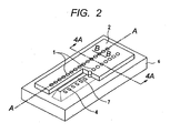
- FIG. 2 is a schematic perspective view of the exemplary structure of the liquid ejection head obtained by the production process according to the first embodiment.
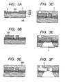
- FIGS. 3A, 3B, 3C, 3D, 3E and 3F are sectional process views illustrating the production process according to the first embodiment.
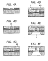
- FIGS. 4A, 4B, 4C, 4D, 4E and 4F are sectional process views illustrating the production process according to the first embodiment.
- FIGS. 5A, 5B, 5C and 5D are schematic views illustrating a state after second exposure treatment is carried out.
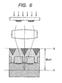
- FIG. 6 is a conceptual diagram of exposure in the second exposure treatment.
- FIGS. 7A, 7B, 7C and 7D are schematic views illustrating a state in which first exposure treatment is carried out after the second exposure treatment is carried out.
- FIG. 8 is a conceptual diagram of exposure in the first exposure treatment.
- FIGS. 9A, 9B and 9C are schematic views illustrating a state after development treatment according to the first embodiment is carried out.
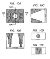
- FIGS. 10A, 10B, 10C, 10D and 10E are schematic views illustrating the vicinity of an ejection orifice obtained under exposure conditions of a second embodiment of the present invention.
- FIG. 2 is a schematic perspective view illustrating an exemplary structure of an ink jet recording head produced according to a first embodiment of the present invention.
- the ink jet recording head (liquid ejection head) includes a silicon substrate 6 in which two lines of ejection energy generating elements 4 are formed in an arrangement direction at a predetermined pitch.
- An ink supply port (liquid supply port) 7 opens in the silicon substrate 6 between the two lines of the ejection energy generating elements 4.
- Ink ejection orifices (liquid ejection orifices) 1 for ejecting ink and ink flow paths (liquid flow paths) 5 which communicate with the ink supply port 7 and with the ink ejection orifices 1, respectively, are formed by a flow path forming member 2 on the silicon substrate 6.
- the ink ejection orifices 1 open over the ejection energy generating elements 4, respectively, and are provided in two lines in the arrangement direction.
- the ink jet recording head is arranged so that a surface thereof in which the ink ejection orifices 1 are formed faces a recording surface of a recording medium.
- FIG. 1A is a plan view of the ejection orifices illustrated in FIG. 2
- FIG. 1B is a sectional view taken along the line 1B-1B of FIG. 1A
- FIG. 1C is a sectional view taken along the line 1C-1C of FIG. 1A
- the line 1B-1B indicates the arrangement direction while the line 1C-1C indicates an orthogonal direction which is orthogonal to the arrangement direction. Therefore, FIG. 1B illustrates a shape in cross section of the ejection orifices taken along a surface perpendicular to the orthogonal direction while FIG. 1C illustrates a shape in cross section of the ejection orifice taken along a surface perpendicular to the arrangement direction.
- each of the ejection orifices formed according to this embodiment has a side wall along the orthogonal direction.
- the shape in cross section of each of the ejection orifices taken along the surface perpendicular to the orthogonal direction is a tapered shape or a quadrangular shape.
- the shape in cross section of each of the ejection orifices taken along the surface perpendicular to the arrangement direction is a tapered shape.
- the production process according to this embodiment includes the following steps.
- a step of preparing a substrate provided with a resin layer containing a photocurable resin (1) A step of preparing a substrate provided with a resin layer containing a photocurable resin.
- the present invention has such a feature that the inclination angle of a side wall of the ejection orifices formed by the first exposure treatment with respect to the substrate differs from the inclination angle of a side wall of the ejection orifices formed by the second exposure treatment with respect to the substrate.
- the first exposure treatment be of a treatment of subjecting a portion of the resin layer corresponding to the side wall along the orthogonal direction to exposure so that a ratio b/a is equal to or larger than one, where 'a' is a width in the arrangement direction of a front side opening of the ejection orifice and 'b' is a width in the arrangement direction of a back side opening of the ejection orifice.
- the second exposure treatment be of a treatment of subjecting a portion of the resin layer corresponding to other side walls than the side wall along the orthogonal direction to exposure so that a ratio d/c is larger than one, where 'c' is a width in the orthogonal direction of the front side opening of the ejection orifice and 'd' is a width in the orthogonal direction of the back side opening of the ejection orifice.
- the first exposure treatment and the second exposure treatment be carried out so that the ratio d/c is larger than the ratio b/a.
- the shape in cross section of the ejection orifices taken along a surface perpendicular to the orthogonal direction be a tapered shape or a quadrangular shape.
- the shape in cross section of the ejection orifices taken along a surface perpendicular to the arrangement direction be a tapered shape. Note that, even when both of those cross section shapes are tapered shapes, the inclination angles thereof with respect to the substrate are different from each other.
- the width a and the width b be the width of an upper side and the width of a lower side, respectively, of a shape in cross section of the ejection orifice taken along a surface which is perpendicular to the arrangement direction and which passes through the center of the ejection orifice.
- the width c and the width d be the width of an upper side and the width of a lower side, respectively, of a shape in cross section of the ejection orifice taken along a surface which is perpendicular to the orthogonal direction and which passes through the center of the ejection orifice.
- a liquid ejection head including a substrate and an ejection orifice member provided on the substrate in which a plurality of ejection orifices for ejecting liquid are provided along an arrangement direction, in which a side wall along an orthogonal direction orthogonal to the arrangement direction of the plurality of ejection orifices is perpendicular to the substrate and a side wall along the arrangement direction of the plurality of ejection orifices forms an acute angle with respect to the substrate.
- an ink jet recording head is described as an example to which the present invention may be applied, but the scope of application of the present invention is not limited thereto. Further, the present invention may be applied not only a process for producing an ink jet recording head but also to a process for producing a liquid ejection head, which is used for manufacturing a biochip or for printing an electronic circuit.
- a liquid ejection head includes an ink jet recording head, a head for manufacturing a color filter, and the like.
- a nozzle density as used in this embodiment refers to the number of nozzles per unit length in a direction of the line 1B-1B of FIG. 1A .
- the nozzle density may be, for example, 1,200 DPI (dots/inch).
- FIGS. 3A to 3F illustrate exemplary steps in the production process according to this embodiment.
- FIGS. 3A to 3F illustrate the steps in cross section taken along a surface which is perpendicular to the arrangement direction.
- a silicon substrate 6 having an ejection energy generating element 4 arranged therein is prepared.
- the silicon substrate 6 has a crystal orientation of, for example, (100) surface. Note that, in this embodiment, a case where the (100) surface is used is described, but the plane orientation which may be used in the present invention is not limited thereto.
- a thermally oxidized film 301 and a sacrifice layer 302 are formed on the silicon substrate 6.
- a silicon oxide film 303 which is an insulating layer is formed on the thermally oxidized film 301.
- a plurality of ejection energy generating elements 4 such as heat generating resistors are arranged on the silicon oxide film 303.
- a silicon nitride film 304 as a protective film is formed on the silicon oxide film 303 and the ejection energy generating elements 4.
- the sacrifice layer 302 By forming the sacrifice layer 302, a surface opening of an ink supply port (liquid supply port) can be formed with good precision.
- the sacrifice layer contains aluminum and may be etched by an etchant for a silicon substrate (alkaline solution).
- aluminum (Al), aluminum silicon (AlSi), aluminum copper (AlCu), or aluminum silicon copper (AlSiCu) may be used.
- AlSi is a compound containing Al and Si
- AlCu is a compound containing Al and Cu
- AlSiCu is a compound containing Al, Si, and Cu.
- an adhesion-improving layer 3 is formed on the silicon nitride film 304.
- a polyetheramide resin may be used.
- the adhesion-improving layer 3 may be applied and arranged by spin coating or the like.
- the polyetheramide resin for example, specifically, a material produced by Hitachi Chemical Co., Ltd. under the trade name of HIMAL-1200 may be used.
- the thickness of the adhesion-improving layer 3 is, for example, 2 ⁇ m.
- a dissolvable resin is used to form a flow path form material 307 to be a form of an ink flow path is formed on the silicon substrate 6 including the ejection energy generating element 4.
- the flow path form material 307 may be formed by, for example, applying a positive resist by spin coating or the like and then carrying out exposure and development with ultraviolet radiation, deep UV radiation, or the like.
- a positive resist for example, ODUR (trade name, produced by TOKYO OHKA KOGYO CO., LTD.) may be used.
- a negative photosensitive resin 308 is arranged on the adhesion-improving layer 3 and the flow path form material 307 by spin coating or the like.
- a negative photosensitive resin is used as the flow path forming member.
- a negative photosensitive resin is cured by exposure.
- a negative photosensitive resin one which is sensitive to the i-line is preferred.
- the thickness of the negative photosensitive resin is, for example, 30 ⁇ m.
- an i-line stepper may be used, though the present invention is not limited thereto.
- an i-line stepper for example, a stepper FPA-3000I5+ produced by Canon Inc. may be used.
- the negative photosensitive resin 308 is patterned by exposure and development to form the flow path forming member 2 having the ink ejection orifice 1.
- the exposure is carried out at least twice, i.e., first exposure treatment and second exposure treatment.
- the flow path forming member is also a member which forms the ejection orifices, and thus, may also be referred to as an ejection orifice member.
- first exposure treatment and the second exposure treatment are described in detail with reference to FIGS. 5A to 9C .
- the second exposure treatment is first described, but any one of the first exposure treatment and the second exposure treatment may be carried out first, and the order is not specifically limited in the present invention.
- FIG. 5A is a schematic plan view for illustrating a state in the vicinity of ejection orifices after the second exposure treatment is carried out.
- FIG. 5B is a sectional view taken along the line 5B-5B of FIG. 5A.
- FIG. 5C is a sectional view taken along the line 5C-5C of FIG. 5A.
- FIG. 5D is a schematic view of a second mask used in the second exposure treatment.
- FIGS. 5A to 5C illustrate an unexposed portion 501, an exposed portion (cured portion) 502, and a flow path form material 507. Further, FIG. 5D illustrates a light impermeable portion 511 and a light permeable portion 512 of the second mask.
- the second exposure treatment is of a treatment of subjecting a portion of the resin layer corresponding to other side walls than the side wall along the orthogonal direction to exposure so that the ratio d/c is larger than 1, where c is the width in the orthogonal direction of the front side opening of the ejection orifice and d is the width in the orthogonal direction of the back side opening of the ejection orifice.
- the second exposure may be carried out, for example, using a stepper FPA-3000I5+ produced by Canon Inc. under the following exposure conditions: an aperture ratio (NA) of 0.45; the coherence factor ( ⁇ ) of 0.5; an amount of exposure of 4,000 J, and a focus offset (focus) of -50 ⁇ m.
- NA aperture ratio
- ⁇ coherence factor
- focus focus offset
- the amount of exposure is selected on the assumption that the film thickness is 30 ⁇ m.
- FIG. 6 illustrates the concept of the above-mentioned exposure conditions in the second exposure treatment.
- the stepper regards an uppermost surface of an object to be subjected to exposure as a reference level, and thus, the focus position in exposure is -50 ⁇ m which is below the surface of the substrate.
- the dotted line E indicates the focus reference level while the dotted line F indicates the focus position.
- the stepper FPA-3000I5+ produced by Canon Inc. is used as the exposure machine and the thickness of the film is 30 ⁇ m, the following relationship has been confirmed.
- the shape is straight under the following exposure conditions: NA of 0.45; ⁇ of 0.3; and the focus of -15 ⁇ m.
- NA 0.45
- ⁇ 0.5
- the focus is -50 ⁇ m
- the tapered angle is 7 degrees.
- the tapered angle as used herein is, as illustrated in FIG. 1C , an angle ⁇ formed between a virtual line drawn perpendicularly from an end of the front side opening of the ejection orifice and the wall of the ejection orifice.
- FIG. 7A is a schematic plan view for illustrating a state in the vicinity of the ejection orifices after the first exposure treatment is carried out.
- FIG. 7B is a sectional view taken along the line 7B-7B of FIG. 7A.
- FIG. 7C is a sectional view taken along the line 7C-7C of FIG. 7A.
- FIG. 7D is a schematic view of a first mask used in the first exposure treatment.
- FIGS. 7A to 7C illustrate an unexposed portion 701, an exposed portion (cured portion) 702, and a flow path form material 707. Further, FIG. 7D illustrates a light impermeable portion 711 and a light permeable portion 712 of the first mask.
- the exposure conditions of the first exposure treatment are, for example, NA of 0.45, ⁇ of 0.30, amount of exposure of 4,000 J, and focus of -15 ⁇ m.
- FIG. 8 illustrates the concept of the above-mentioned exposure conditions in the first exposure treatment.
- the stepper regards an uppermost surface of an object to be subjected to exposure as a reference level, and thus, the focus position in exposure is -15 ⁇ m which is in the center of a structure.
- FIG. 9A is a schematic plan view illustrating the vicinity of the ejection orifices after the second exposure treatment, the first exposure treatment, and then post exposure bake (PEB) and development are completed.
- FIG. 9B is a sectional view taken along the line 9B-9B of FIG. 9A.
- FIG. 9C is a sectional view taken along the line 9C-9C of FIG. 9A .
- PEB and development are carried out to obtain the flow path forming member having the ejection orifice 1. Even if the order of the first exposure treatment and the second exposure treatment is changed, a problem is not caused in forming the nozzles.
- the masks illustrated in the figures are only exemplary and are not the only one combination for forming the shape according to the present invention. Masks of other designs may also form the shape according to the present invention.
- FIG. 3D is a schematic sectional view illustrating a state in which the ejection orifice 1 is formed as described above.
- the thermally oxidized film 301 at the back of the silicon substrate 6 is patterned to expose a silicon surface to be a starting surface of anisotropic etching.
- silicon anisotropic etching is carried out to form an ink supply port 7.
- the ink supply port 7 may be formed by, for example, anisotropic etching with a strongly alkaline solution such as TMAH or KOH.
- the silicon oxide film 303 is removed by wet etching with a hydrofluoric acid liquid.
- the silicon nitride film 304 is removed by dry etching or the like.
- the ink flow path 5 is formed.
- ultrasonic immersion may be used in combination as necessary to remove the flow path form material 307 easily.
- FIGS. 4A to 4F are schematic views illustrating steps of an exemplary production process according to this embodiment. Further, FIGS. 4A to 4F are sectional views taken along the line 4A-4A of FIG. 2 .
- FIG. 4A is similar to FIG. 3A .
- a flow path wall 401 which is to form a side wall of the ink flow path is formed with a nozzle material by applying a photosensitive resin material and carrying out exposure, PEB, and development thereon.
- a photosensitive dry film 402 is arranged on the flow path wall 401.
- an ink supply port 7 is formed. Further, as illustrated in FIG. 4F , the ink flow path is formed.
- Exposure conditions according to a second embodiment of the present invention are specifically described in the following.
- FIG. 10A is a schematic plan view illustrating the vicinity of the ejection orifices after the first exposure treatment and the second exposure treatment are carried out.
- FIG. 10B is a sectional view taken along the line 10B-10B of FIG. 10A.
- FIG. 10C is a sectional view taken along the line 10C-10C of FIG. 10A.
- FIGS. 10D and 10E are schematic views of masks used in exposure in this embodiment.
- FIG. 10D is a mask used in the second exposure treatment while FIG. 10E is a mask used in the first exposure treatment.
- the exposure conditions are set on the assumption that the film thickness of a negative resin material is 80 ⁇ m. Further, in the exposure a stepper similarly to the first embodiment described above is used.
- the exposure conditions of the second exposure treatment are NA of 0.63, ⁇ of 0.30, amount of exposure of 5,500 J, and focus of -75 ⁇ m.
- the exposure conditions of the first exposure are NA of 0.45, ⁇ of 0.30, amount of exposure of 5,500 J, and focus of -40 ⁇ m.
- the amount of exposure is 5,000 J.
- the tapered angle in the first embodiment described above and the tapered angle in this embodiment are the same and still the exposure conditions are changed is that the shape of an end of an ejection orifice varies depending on the film thickness.
- a liquid ejection head including an ejection orifice member that has an ejection orifice with a reduced flow resistance and that has satisfactory strength can be produced with high yield.
Claims (6)
- Procédé de production d'une tête d'éjection de liquide comportant, sur une surface d'un substrat (6), un élément à orifices d'éjection (2) comportant une pluralité d'orifices d'éjection (1) pour éjecter un liquide sensiblement perpendiculairement à la surface du substrat, disposés suivant une direction d'agencement (A), le procédé consistant à :préparer le substrat muni d'une couche de résine (308) contenant une résine photodurcissable ;effectuer un premier traitement d'exposition et un second traitement d'exposition qui consistent chacun à soumettre la couche de résine à une exposition ; etformer les orifices d'éjection à partir de la couche de résine soumise au premier traitement d'exposition et au second traitement d'exposition,caractérisé en ce quele premier traitement d'exposition consiste à soumettre à une exposition une partie (702) de la couche de résine correspondant à des premières parties de parois latérales qui définissent deux surfaces internes d'un orifice d'éjection à des extrémités opposées dans la direction d'agencement et sur le côté de la sortie d'écoulement de liquide de l'orifice d'éjection ;le second traitement d'exposition consiste à soumettre à une exposition une partie (502) de la couche de résine correspondant à des secondes parties de parois latérales qui définissent deux surfaces internes du même orifice d'éjection à des extrémités opposées dans une direction orthogonale (B), orthogonale à la direction d'agencement et parallèle à la surface du substrat, et sur le côté de la sortie d'écoulement de liquide de l'orifice d'éjection ; etun angle d'inclinaison des premières parties de parois latérales par rapport à la surface du substrat est différent d'un angle d'inclinaison des secondes parties de parois latérales par rapport à la surface du substrat.
- Procédé de production d'une tête d'éjection de liquide selon la revendication 1, dans lequel :le premier traitement d'exposition consiste à soumettre à une exposition la partie de la couche de résine correspondant aux premières parties de parois latérales de façon qu'un rapport b/a soit égal ou supérieur à un, 'a' représentant une largeur, dans la direction d'agencement, d'une ouverture de face avant des orifices d'éjection et 'b' représentant une largeur, dans la direction d'agencement, d'une ouverture de face arrière des orifices d'éjection ;le second traitement d'exposition consiste à soumettre à une exposition la partie de la couche de résine correspondant aux secondes parties de parois latérales de façon qu'un rapport d/c soit supérieur à un, 'c' représentant une largeur, dans la direction orthogonale, de l'ouverture de face avant des orifices d'éjection et 'd' représentant une largeur, dans la direction orthogonale, de l'ouverture de face arrière des orifices d'éjection ; etle rapport d/c est supérieur au rapport b/a.
- Procédé de production d'une tête d'éjection de liquide selon la revendication 1 ou 2, dans lequel une forme en coupe transversale des orifices d'éjection prise le long d'un premier plan (1C-1C) parallèle à la direction orthogonale, perpendiculaire à la surface du substrat, et passant par le centre d'un orifice d'éjection, est une forme biseautée.
- Procédé de production d'une tête d'éjection de liquide selon le la revendication 1 ou 2, dans lequel une forme en coupe transversale des orifices d'éjection, prise le long d'un second plan (1B-1B) parallèle à la direction d'agencement, perpendiculaire à la surface du substrat, et passant par le centre d'un orifice d'éjection, est l'une d'une forme biseautée et d'une forme quadrangulaire.
- Procédé de production d'une tête d'éjection de liquide selon la revendication 2, dans lequel :la largeur a et la largeur b sont une largeur d'une face supérieure et une largeur d'une face inférieure, respectivement, d'une forme en coupe transversale des orifices d'éjection, prise le long d'un second plan (1B-1B) parallèle à la direction d'agencement, perpendiculaire à la surface du substrat, et passant par le centre d'un orifice d'éjection ; etla largeur c et la largeur d sont une largeur d'une face supérieure et une largeur d'une face inférieure, respectivement, d'une forme en coupe transversale des orifices d'éjection, prise le long d'un premier plan (1C-1C) parallèle à la direction orthogonale, perpendiculaire à la surface du substrat, et passant par le centre d'un orifice d'éjection.
- Tête d'éjection de liquide, comprenant :un substrat (6) ; etun élément à orifices d'éjection (2) disposé au niveau d'une surface du substrat, l'élément à orifices d'éjection ayant une pluralité d'orifices d'éjection (1) destinés à éjecter du liquide sensiblement perpendiculairement à la surface du substrat, disposés le long d'une direction d'agencement (A),dans lequell'élément à orifices d'éjection comprend des premières et secondes parties de parois latérales, dans lequelles premières parties de parois latérales définissent deux surfaces internes d'un orifice d'éjection à des extrémités opposées dans la direction d'agencement, et sur le côté de la sortie d'écoulement de liquide de l'orifice d'éjection ;les secondes parties de parois latérales définissent deux surfaces internes du même orifice d'éjection à des extrémités opposées dans une direction orthogonale (B), orthogonale à la direction d'agencement et parallèle à la surface du substrat, et sur le côté de la sortie d'écoulement de liquide de l'orifice d'éjection ;caractérisée en ce que :les premières parties de parois latérales sont perpendiculaires à la surface du substrat ; etdeux coupes transversales des secondes parties de parois latérales prises le long d'un plan (1C-1C) parallèle à la direction orthogonale, perpendiculaire à la surface du substrat, et passant par le centre de l'orifice d'éjection, forment une forme biseautée vers la sortie d'écoulement de liquide de l'orifice d'éjection.
Applications Claiming Priority (1)
| Application Number | Priority Date | Filing Date | Title |
|---|---|---|---|
| JP2011042028 | 2011-02-28 |
Publications (2)
| Publication Number | Publication Date |
|---|---|
| EP2492096A1 EP2492096A1 (fr) | 2012-08-29 |
| EP2492096B1 true EP2492096B1 (fr) | 2015-04-08 |
Family
ID=45654831
Family Applications (1)
| Application Number | Title | Priority Date | Filing Date |
|---|---|---|---|
| EP20120000676 Not-in-force EP2492096B1 (fr) | 2011-02-28 | 2012-02-01 | Tête d'éjection de liquide et son procédé de production |
Country Status (7)
| Country | Link |
|---|---|
| US (1) | US8652767B2 (fr) |
| EP (1) | EP2492096B1 (fr) |
| JP (1) | JP5460760B2 (fr) |
| KR (1) | KR101438267B1 (fr) |
| CN (1) | CN102673156B (fr) |
| BR (1) | BR102012004467A2 (fr) |
| RU (1) | RU2507073C2 (fr) |
Families Citing this family (7)
| Publication number | Priority date | Publication date | Assignee | Title |
|---|---|---|---|---|
| JP6008556B2 (ja) * | 2012-04-25 | 2016-10-19 | キヤノン株式会社 | 液体吐出ヘッドの製造方法及び露光方法 |
| US9308728B2 (en) * | 2013-05-31 | 2016-04-12 | Stmicroelectronics, Inc. | Method of making inkjet print heads having inkjet chambers and orifices formed in a wafer and related devices |
| JP6137950B2 (ja) | 2013-06-10 | 2017-05-31 | キヤノン株式会社 | 液体吐出ヘッドの製造方法 |
| JP2015052754A (ja) * | 2013-09-09 | 2015-03-19 | 富士フイルム株式会社 | 樹脂硬化物の製造方法、並びにこれを用いた固体撮像素子および液晶表示装置の製造方法 |
| US9776409B2 (en) | 2014-04-24 | 2017-10-03 | Hewlett-Packard Development Company, L.P. | Fluidic ejection device with layers having different light sensitivities |
| JP6929639B2 (ja) * | 2016-01-08 | 2021-09-01 | キヤノン株式会社 | 液体吐出ヘッド、液体吐出装置及び液体の供給方法 |
| US10040290B2 (en) | 2016-01-08 | 2018-08-07 | Canon Kabushiki Kaisha | Liquid ejection head, liquid ejection apparatus, and method of supplying liquid |
Family Cites Families (16)
| Publication number | Priority date | Publication date | Assignee | Title |
|---|---|---|---|---|
| ES2069699T3 (es) | 1989-09-18 | 1995-05-16 | Canon Kk | Cabezal para la impresion por chorros de tinta, cartucho y aparato. |
| JPH09207341A (ja) | 1996-02-07 | 1997-08-12 | Seiko Epson Corp | インクジェットヘッド用ノズルプレートおよびその製造方法 |
| JPH09216368A (ja) | 1996-02-13 | 1997-08-19 | Seiko Epson Corp | インクジェットノズルプレートおよびその製造方法 |
| JPH09234871A (ja) | 1996-02-28 | 1997-09-09 | Brother Ind Ltd | ノズルプレートの接着構造とその接着方法 |
| US6955417B2 (en) | 2002-03-28 | 2005-10-18 | Fuji Photo Film Co., Ltd. | Inkjet recording head and inkjet printer |
| JP2004175038A (ja) * | 2002-11-28 | 2004-06-24 | Sharp Corp | インク吐出装置及びその製造方法 |
| JP2005007654A (ja) * | 2003-06-17 | 2005-01-13 | Seiko Epson Corp | インクジェットヘッドの製造方法及びインクジェットヘッド |
| US20050130075A1 (en) | 2003-12-12 | 2005-06-16 | Mohammed Shaarawi | Method for making fluid emitter orifice |
| US7585616B2 (en) * | 2005-01-31 | 2009-09-08 | Hewlett-Packard Development Company, L.P. | Method for making fluid emitter orifice |
| JP4834426B2 (ja) | 2006-03-06 | 2011-12-14 | キヤノン株式会社 | インクジェット記録ヘッドの製造方法 |
| JP2008119955A (ja) | 2006-11-13 | 2008-05-29 | Canon Inc | インクジェット記録ヘッド及び該ヘッドの製造方法 |
| US7971964B2 (en) * | 2006-12-22 | 2011-07-05 | Canon Kabushiki Kaisha | Liquid discharge head and method for manufacturing the same |
| US8273524B2 (en) * | 2007-06-18 | 2012-09-25 | Canon Kabushiki Kaisha | Liquid discharging head, producing method thereof, structure, and producing method thereof |
| US20090136875A1 (en) * | 2007-11-15 | 2009-05-28 | Canon Kabushiki Kaisha | Manufacturing method of liquid ejection head |
| JP5511191B2 (ja) * | 2008-01-28 | 2014-06-04 | キヤノン株式会社 | 液体吐出ヘッド、液体吐出ヘッドの製造方法および構造体の形成方法 |
| JP2009220286A (ja) | 2008-03-13 | 2009-10-01 | Canon Inc | 液体吐出記録ヘッド及その製造方法 |
-
2012
- 2012-01-26 US US13/359,249 patent/US8652767B2/en not_active Expired - Fee Related
- 2012-02-01 EP EP20120000676 patent/EP2492096B1/fr not_active Not-in-force
- 2012-02-07 JP JP2012024153A patent/JP5460760B2/ja active Active
- 2012-02-20 KR KR20120016854A patent/KR101438267B1/ko active IP Right Grant
- 2012-02-27 RU RU2012107068/12A patent/RU2507073C2/ru not_active IP Right Cessation
- 2012-02-28 BR BR102012004467A patent/BR102012004467A2/pt not_active Application Discontinuation
- 2012-02-28 CN CN201210048283.8A patent/CN102673156B/zh not_active Expired - Fee Related
Also Published As
| Publication number | Publication date |
|---|---|
| CN102673156B (zh) | 2014-10-29 |
| RU2012107068A (ru) | 2013-09-10 |
| EP2492096A1 (fr) | 2012-08-29 |
| BR102012004467A2 (pt) | 2013-07-23 |
| JP2012192729A (ja) | 2012-10-11 |
| KR101438267B1 (ko) | 2014-09-04 |
| CN102673156A (zh) | 2012-09-19 |
| KR20120098434A (ko) | 2012-09-05 |
| RU2507073C2 (ru) | 2014-02-20 |
| US20120218350A1 (en) | 2012-08-30 |
| JP5460760B2 (ja) | 2014-04-02 |
| US8652767B2 (en) | 2014-02-18 |
Similar Documents
| Publication | Publication Date | Title |
|---|---|---|
| EP2492096B1 (fr) | Tête d'éjection de liquide et son procédé de production | |
| JP4455282B2 (ja) | インクジェットヘッドの製造方法、インクジェットヘッドおよびインクジェットカートリッジ | |
| JP5031492B2 (ja) | インクジェットヘッド基板の製造方法 | |
| US6158846A (en) | Forming refill for monolithic inkjet printhead | |
| JP5143274B2 (ja) | インクジェットヘッドおよびその製造方法 | |
| JP4480182B2 (ja) | インクジェット記録ヘッド用基板及びインクジェット記録ヘッドの製造方法 | |
| US20070212891A1 (en) | Manufacturing method of substrate for ink jet head and manufacturing method of ink jet recording head | |
| JP4119379B2 (ja) | バブルインクジェットヘッドおよびその製造方法 | |
| US20060017785A1 (en) | Ink jet head including a filtering member integrally formed with a substrate and method of fabricating the same | |
| US8191998B2 (en) | Liquid ejecting head | |
| US20090314742A1 (en) | Method for processing substrate and method for producing liquid ejection head and substrate for liquid ejection head | |
| CA2134385C (fr) | Methode et appareil servant a eliminer les gouttes satellites mal dirigees dans une tete thermique d'impression par jet d'encre | |
| KR100612326B1 (ko) | 잉크젯 헤드의 제조방법 | |
| KR20120043139A (ko) | 액체 토출 헤드용 기판의 제조 방법 | |
| JP5111477B2 (ja) | インクジェットヘッド | |
| JP2012101364A (ja) | 吐出素子基板の製造方法 | |
| JP4974751B2 (ja) | インクジェットヘッドおよびその製造方法 | |
| JP2012121168A (ja) | 液体吐出ヘッド及びその製造方法 | |
| JP3147446B2 (ja) | インクジェット記録ヘッドおよびその製造方法 | |
| JP2006082331A (ja) | インクジェット記録ヘッドの製造方法 | |
| JP2007296694A (ja) | インクジェット記録ヘッドの製造方法 | |
| JP2002067327A (ja) | 液滴噴射記録装置および構造体の製造方法 | |
| JP2007125725A (ja) | インクジェット記録ヘッドの製造方法、及びインクジェット記録ヘッド | |
| JPH08281952A (ja) | 液体噴射記録ヘッドの製造方法 | |
| JP2007021798A (ja) | インクジェット記録ヘッド用基板の製造方法 |
Legal Events
| Date | Code | Title | Description |
|---|---|---|---|
| PUAI | Public reference made under article 153(3) epc to a published international application that has entered the european phase |
Free format text: ORIGINAL CODE: 0009012 |
|
| AK | Designated contracting states |
Kind code of ref document: A1 Designated state(s): AL AT BE BG CH CY CZ DE DK EE ES FI FR GB GR HR HU IE IS IT LI LT LU LV MC MK MT NL NO PL PT RO RS SE SI SK SM TR |
|
| AX | Request for extension of the european patent |
Extension state: BA ME |
|
| 17P | Request for examination filed |
Effective date: 20130228 |
|
| 17Q | First examination report despatched |
Effective date: 20130812 |
|
| GRAP | Despatch of communication of intention to grant a patent |
Free format text: ORIGINAL CODE: EPIDOSNIGR1 |
|
| INTG | Intention to grant announced |
Effective date: 20140903 |
|
| GRAS | Grant fee paid |
Free format text: ORIGINAL CODE: EPIDOSNIGR3 |
|
| GRAA | (expected) grant |
Free format text: ORIGINAL CODE: 0009210 |
|
| AK | Designated contracting states |
Kind code of ref document: B1 Designated state(s): AL AT BE BG CH CY CZ DE DK EE ES FI FR GB GR HR HU IE IS IT LI LT LU LV MC MK MT NL NO PL PT RO RS SE SI SK SM TR |
|
| REG | Reference to a national code |
Ref country code: GB Ref legal event code: FG4D |
|
| REG | Reference to a national code |
Ref country code: CH Ref legal event code: EP |
|
| REG | Reference to a national code |
Ref country code: IE Ref legal event code: FG4D |
|
| REG | Reference to a national code |
Ref country code: AT Ref legal event code: REF Ref document number: 720214 Country of ref document: AT Kind code of ref document: T Effective date: 20150515 |
|
| REG | Reference to a national code |
Ref country code: DE Ref legal event code: R096 Ref document number: 602012006385 Country of ref document: DE Effective date: 20150521 |
|
| REG | Reference to a national code |
Ref country code: AT Ref legal event code: MK05 Ref document number: 720214 Country of ref document: AT Kind code of ref document: T Effective date: 20150408 |
|
| REG | Reference to a national code |
Ref country code: NL Ref legal event code: VDEP Effective date: 20150408 |
|
| REG | Reference to a national code |
Ref country code: LT Ref legal event code: MG4D |
|
| PG25 | Lapsed in a contracting state [announced via postgrant information from national office to epo] |
Ref country code: NL Free format text: LAPSE BECAUSE OF FAILURE TO SUBMIT A TRANSLATION OF THE DESCRIPTION OR TO PAY THE FEE WITHIN THE PRESCRIBED TIME-LIMIT Effective date: 20150408 |
|
| PG25 | Lapsed in a contracting state [announced via postgrant information from national office to epo] |
Ref country code: FI Free format text: LAPSE BECAUSE OF FAILURE TO SUBMIT A TRANSLATION OF THE DESCRIPTION OR TO PAY THE FEE WITHIN THE PRESCRIBED TIME-LIMIT Effective date: 20150408 Ref country code: NO Free format text: LAPSE BECAUSE OF FAILURE TO SUBMIT A TRANSLATION OF THE DESCRIPTION OR TO PAY THE FEE WITHIN THE PRESCRIBED TIME-LIMIT Effective date: 20150708 Ref country code: ES Free format text: LAPSE BECAUSE OF FAILURE TO SUBMIT A TRANSLATION OF THE DESCRIPTION OR TO PAY THE FEE WITHIN THE PRESCRIBED TIME-LIMIT Effective date: 20150408 Ref country code: HR Free format text: LAPSE BECAUSE OF FAILURE TO SUBMIT A TRANSLATION OF THE DESCRIPTION OR TO PAY THE FEE WITHIN THE PRESCRIBED TIME-LIMIT Effective date: 20150408 Ref country code: LT Free format text: LAPSE BECAUSE OF FAILURE TO SUBMIT A TRANSLATION OF THE DESCRIPTION OR TO PAY THE FEE WITHIN THE PRESCRIBED TIME-LIMIT Effective date: 20150408 Ref country code: PT Free format text: LAPSE BECAUSE OF FAILURE TO SUBMIT A TRANSLATION OF THE DESCRIPTION OR TO PAY THE FEE WITHIN THE PRESCRIBED TIME-LIMIT Effective date: 20150810 |
|
| PG25 | Lapsed in a contracting state [announced via postgrant information from national office to epo] |
Ref country code: GR Free format text: LAPSE BECAUSE OF FAILURE TO SUBMIT A TRANSLATION OF THE DESCRIPTION OR TO PAY THE FEE WITHIN THE PRESCRIBED TIME-LIMIT Effective date: 20150709 Ref country code: RS Free format text: LAPSE BECAUSE OF FAILURE TO SUBMIT A TRANSLATION OF THE DESCRIPTION OR TO PAY THE FEE WITHIN THE PRESCRIBED TIME-LIMIT Effective date: 20150408 Ref country code: LV Free format text: LAPSE BECAUSE OF FAILURE TO SUBMIT A TRANSLATION OF THE DESCRIPTION OR TO PAY THE FEE WITHIN THE PRESCRIBED TIME-LIMIT Effective date: 20150408 Ref country code: AT Free format text: LAPSE BECAUSE OF FAILURE TO SUBMIT A TRANSLATION OF THE DESCRIPTION OR TO PAY THE FEE WITHIN THE PRESCRIBED TIME-LIMIT Effective date: 20150408 Ref country code: IS Free format text: LAPSE BECAUSE OF FAILURE TO SUBMIT A TRANSLATION OF THE DESCRIPTION OR TO PAY THE FEE WITHIN THE PRESCRIBED TIME-LIMIT Effective date: 20150808 |
|
| REG | Reference to a national code |
Ref country code: DE Ref legal event code: R097 Ref document number: 602012006385 Country of ref document: DE |
|
| PG25 | Lapsed in a contracting state [announced via postgrant information from national office to epo] |
Ref country code: EE Free format text: LAPSE BECAUSE OF FAILURE TO SUBMIT A TRANSLATION OF THE DESCRIPTION OR TO PAY THE FEE WITHIN THE PRESCRIBED TIME-LIMIT Effective date: 20150408 Ref country code: DK Free format text: LAPSE BECAUSE OF FAILURE TO SUBMIT A TRANSLATION OF THE DESCRIPTION OR TO PAY THE FEE WITHIN THE PRESCRIBED TIME-LIMIT Effective date: 20150408 |
|
| PLBE | No opposition filed within time limit |
Free format text: ORIGINAL CODE: 0009261 |
|
| STAA | Information on the status of an ep patent application or granted ep patent |
Free format text: STATUS: NO OPPOSITION FILED WITHIN TIME LIMIT |
|
| PG25 | Lapsed in a contracting state [announced via postgrant information from national office to epo] |
Ref country code: PL Free format text: LAPSE BECAUSE OF FAILURE TO SUBMIT A TRANSLATION OF THE DESCRIPTION OR TO PAY THE FEE WITHIN THE PRESCRIBED TIME-LIMIT Effective date: 20150408 Ref country code: RO Free format text: LAPSE BECAUSE OF NON-PAYMENT OF DUE FEES Effective date: 20150408 Ref country code: SK Free format text: LAPSE BECAUSE OF FAILURE TO SUBMIT A TRANSLATION OF THE DESCRIPTION OR TO PAY THE FEE WITHIN THE PRESCRIBED TIME-LIMIT Effective date: 20150408 Ref country code: CZ Free format text: LAPSE BECAUSE OF FAILURE TO SUBMIT A TRANSLATION OF THE DESCRIPTION OR TO PAY THE FEE WITHIN THE PRESCRIBED TIME-LIMIT Effective date: 20150408 |
|
| 26N | No opposition filed |
Effective date: 20160111 |
|
| PG25 | Lapsed in a contracting state [announced via postgrant information from national office to epo] |
Ref country code: IT Free format text: LAPSE BECAUSE OF FAILURE TO SUBMIT A TRANSLATION OF THE DESCRIPTION OR TO PAY THE FEE WITHIN THE PRESCRIBED TIME-LIMIT Effective date: 20150408 |
|
| PG25 | Lapsed in a contracting state [announced via postgrant information from national office to epo] |
Ref country code: SI Free format text: LAPSE BECAUSE OF FAILURE TO SUBMIT A TRANSLATION OF THE DESCRIPTION OR TO PAY THE FEE WITHIN THE PRESCRIBED TIME-LIMIT Effective date: 20150408 Ref country code: BE Free format text: LAPSE BECAUSE OF NON-PAYMENT OF DUE FEES Effective date: 20160229 |
|
| PG25 | Lapsed in a contracting state [announced via postgrant information from national office to epo] |
Ref country code: BE Free format text: LAPSE BECAUSE OF FAILURE TO SUBMIT A TRANSLATION OF THE DESCRIPTION OR TO PAY THE FEE WITHIN THE PRESCRIBED TIME-LIMIT Effective date: 20150408 |
|
| PG25 | Lapsed in a contracting state [announced via postgrant information from national office to epo] |
Ref country code: MC Free format text: LAPSE BECAUSE OF FAILURE TO SUBMIT A TRANSLATION OF THE DESCRIPTION OR TO PAY THE FEE WITHIN THE PRESCRIBED TIME-LIMIT Effective date: 20150408 Ref country code: LU Free format text: LAPSE BECAUSE OF FAILURE TO SUBMIT A TRANSLATION OF THE DESCRIPTION OR TO PAY THE FEE WITHIN THE PRESCRIBED TIME-LIMIT Effective date: 20160201 |
|
| REG | Reference to a national code |
Ref country code: CH Ref legal event code: PL |
|
| GBPC | Gb: european patent ceased through non-payment of renewal fee |
Effective date: 20160201 |
|
| PG25 | Lapsed in a contracting state [announced via postgrant information from national office to epo] |
Ref country code: LI Free format text: LAPSE BECAUSE OF NON-PAYMENT OF DUE FEES Effective date: 20160229 Ref country code: CH Free format text: LAPSE BECAUSE OF NON-PAYMENT OF DUE FEES Effective date: 20160229 |
|
| REG | Reference to a national code |
Ref country code: FR Ref legal event code: ST Effective date: 20161028 |
|
| REG | Reference to a national code |
Ref country code: IE Ref legal event code: MM4A |
|
| PG25 | Lapsed in a contracting state [announced via postgrant information from national office to epo] |
Ref country code: IE Free format text: LAPSE BECAUSE OF NON-PAYMENT OF DUE FEES Effective date: 20160201 Ref country code: FR Free format text: LAPSE BECAUSE OF NON-PAYMENT OF DUE FEES Effective date: 20160229 Ref country code: GB Free format text: LAPSE BECAUSE OF NON-PAYMENT OF DUE FEES Effective date: 20160201 |
|
| PG25 | Lapsed in a contracting state [announced via postgrant information from national office to epo] |
Ref country code: SE Free format text: LAPSE BECAUSE OF FAILURE TO SUBMIT A TRANSLATION OF THE DESCRIPTION OR TO PAY THE FEE WITHIN THE PRESCRIBED TIME-LIMIT Effective date: 20150408 |
|
| PG25 | Lapsed in a contracting state [announced via postgrant information from national office to epo] |
Ref country code: MT Free format text: LAPSE BECAUSE OF FAILURE TO SUBMIT A TRANSLATION OF THE DESCRIPTION OR TO PAY THE FEE WITHIN THE PRESCRIBED TIME-LIMIT Effective date: 20150408 |
|
| PG25 | Lapsed in a contracting state [announced via postgrant information from national office to epo] |
Ref country code: HU Free format text: LAPSE BECAUSE OF FAILURE TO SUBMIT A TRANSLATION OF THE DESCRIPTION OR TO PAY THE FEE WITHIN THE PRESCRIBED TIME-LIMIT; INVALID AB INITIO Effective date: 20120201 Ref country code: SM Free format text: LAPSE BECAUSE OF FAILURE TO SUBMIT A TRANSLATION OF THE DESCRIPTION OR TO PAY THE FEE WITHIN THE PRESCRIBED TIME-LIMIT Effective date: 20150408 Ref country code: CY Free format text: LAPSE BECAUSE OF FAILURE TO SUBMIT A TRANSLATION OF THE DESCRIPTION OR TO PAY THE FEE WITHIN THE PRESCRIBED TIME-LIMIT Effective date: 20150408 |
|
| PG25 | Lapsed in a contracting state [announced via postgrant information from national office to epo] |
Ref country code: MT Free format text: LAPSE BECAUSE OF FAILURE TO SUBMIT A TRANSLATION OF THE DESCRIPTION OR TO PAY THE FEE WITHIN THE PRESCRIBED TIME-LIMIT Effective date: 20160229 Ref country code: MK Free format text: LAPSE BECAUSE OF FAILURE TO SUBMIT A TRANSLATION OF THE DESCRIPTION OR TO PAY THE FEE WITHIN THE PRESCRIBED TIME-LIMIT Effective date: 20150408 Ref country code: TR Free format text: LAPSE BECAUSE OF FAILURE TO SUBMIT A TRANSLATION OF THE DESCRIPTION OR TO PAY THE FEE WITHIN THE PRESCRIBED TIME-LIMIT Effective date: 20150408 |
|
| PG25 | Lapsed in a contracting state [announced via postgrant information from national office to epo] |
Ref country code: BG Free format text: LAPSE BECAUSE OF FAILURE TO SUBMIT A TRANSLATION OF THE DESCRIPTION OR TO PAY THE FEE WITHIN THE PRESCRIBED TIME-LIMIT Effective date: 20150408 |
|
| PG25 | Lapsed in a contracting state [announced via postgrant information from national office to epo] |
Ref country code: AL Free format text: LAPSE BECAUSE OF FAILURE TO SUBMIT A TRANSLATION OF THE DESCRIPTION OR TO PAY THE FEE WITHIN THE PRESCRIBED TIME-LIMIT Effective date: 20150408 |
|
| PGFP | Annual fee paid to national office [announced via postgrant information from national office to epo] |
Ref country code: DE Payment date: 20200429 Year of fee payment: 9 |
|
| REG | Reference to a national code |
Ref country code: DE Ref legal event code: R119 Ref document number: 602012006385 Country of ref document: DE |
|
| PG25 | Lapsed in a contracting state [announced via postgrant information from national office to epo] |
Ref country code: DE Free format text: LAPSE BECAUSE OF NON-PAYMENT OF DUE FEES Effective date: 20210901 |