EP2492084B1 - Process for producing three-dimensionally shaped object and device for producing same - Google Patents
Process for producing three-dimensionally shaped object and device for producing same Download PDFInfo
- Publication number
- EP2492084B1 EP2492084B1 EP10824992.1A EP10824992A EP2492084B1 EP 2492084 B1 EP2492084 B1 EP 2492084B1 EP 10824992 A EP10824992 A EP 10824992A EP 2492084 B1 EP2492084 B1 EP 2492084B1
- Authority
- EP
- European Patent Office
- Prior art keywords
- chamber
- gas flow
- light beam
- localized
- powder layer
- Prior art date
- Legal status (The legal status is an assumption and is not a legal conclusion. Google has not performed a legal analysis and makes no representation as to the accuracy of the status listed.)
- Not-in-force
Links
Images


Classifications
-
- B—PERFORMING OPERATIONS; TRANSPORTING
- B29—WORKING OF PLASTICS; WORKING OF SUBSTANCES IN A PLASTIC STATE IN GENERAL
- B29C—SHAPING OR JOINING OF PLASTICS; SHAPING OF MATERIAL IN A PLASTIC STATE, NOT OTHERWISE PROVIDED FOR; AFTER-TREATMENT OF THE SHAPED PRODUCTS, e.g. REPAIRING
- B29C64/00—Additive manufacturing, i.e. manufacturing of three-dimensional [3D] objects by additive deposition, additive agglomeration or additive layering, e.g. by 3D printing, stereolithography or selective laser sintering
- B29C64/10—Processes of additive manufacturing
- B29C64/141—Processes of additive manufacturing using only solid materials
- B29C64/153—Processes of additive manufacturing using only solid materials using layers of powder being selectively joined, e.g. by selective laser sintering or melting
-
- B—PERFORMING OPERATIONS; TRANSPORTING
- B22—CASTING; POWDER METALLURGY
- B22F—WORKING METALLIC POWDER; MANUFACTURE OF ARTICLES FROM METALLIC POWDER; MAKING METALLIC POWDER; APPARATUS OR DEVICES SPECIALLY ADAPTED FOR METALLIC POWDER
- B22F10/00—Additive manufacturing of workpieces or articles from metallic powder
- B22F10/20—Direct sintering or melting
- B22F10/28—Powder bed fusion, e.g. selective laser melting [SLM] or electron beam melting [EBM]
-
- B—PERFORMING OPERATIONS; TRANSPORTING
- B23—MACHINE TOOLS; METAL-WORKING NOT OTHERWISE PROVIDED FOR
- B23P—METAL-WORKING NOT OTHERWISE PROVIDED FOR; COMBINED OPERATIONS; UNIVERSAL MACHINE TOOLS
- B23P15/00—Making specific metal objects by operations not covered by a single other subclass or a group in this subclass
-
- B—PERFORMING OPERATIONS; TRANSPORTING
- B33—ADDITIVE MANUFACTURING TECHNOLOGY
- B33Y—ADDITIVE MANUFACTURING, i.e. MANUFACTURING OF THREE-DIMENSIONAL [3-D] OBJECTS BY ADDITIVE DEPOSITION, ADDITIVE AGGLOMERATION OR ADDITIVE LAYERING, e.g. BY 3-D PRINTING, STEREOLITHOGRAPHY OR SELECTIVE LASER SINTERING
- B33Y10/00—Processes of additive manufacturing
-
- B—PERFORMING OPERATIONS; TRANSPORTING
- B33—ADDITIVE MANUFACTURING TECHNOLOGY
- B33Y—ADDITIVE MANUFACTURING, i.e. MANUFACTURING OF THREE-DIMENSIONAL [3-D] OBJECTS BY ADDITIVE DEPOSITION, ADDITIVE AGGLOMERATION OR ADDITIVE LAYERING, e.g. BY 3-D PRINTING, STEREOLITHOGRAPHY OR SELECTIVE LASER SINTERING
- B33Y30/00—Apparatus for additive manufacturing; Details thereof or accessories therefor
-
- B—PERFORMING OPERATIONS; TRANSPORTING
- B22—CASTING; POWDER METALLURGY
- B22F—WORKING METALLIC POWDER; MANUFACTURE OF ARTICLES FROM METALLIC POWDER; MAKING METALLIC POWDER; APPARATUS OR DEVICES SPECIALLY ADAPTED FOR METALLIC POWDER
- B22F10/00—Additive manufacturing of workpieces or articles from metallic powder
- B22F10/70—Recycling
- B22F10/77—Recycling of gas
-
- B—PERFORMING OPERATIONS; TRANSPORTING
- B22—CASTING; POWDER METALLURGY
- B22F—WORKING METALLIC POWDER; MANUFACTURE OF ARTICLES FROM METALLIC POWDER; MAKING METALLIC POWDER; APPARATUS OR DEVICES SPECIALLY ADAPTED FOR METALLIC POWDER
- B22F12/00—Apparatus or devices specially adapted for additive manufacturing; Auxiliary means for additive manufacturing; Combinations of additive manufacturing apparatus or devices with other processing apparatus or devices
- B22F12/70—Gas flow means
-
- B—PERFORMING OPERATIONS; TRANSPORTING
- B22—CASTING; POWDER METALLURGY
- B22F—WORKING METALLIC POWDER; MANUFACTURE OF ARTICLES FROM METALLIC POWDER; MAKING METALLIC POWDER; APPARATUS OR DEVICES SPECIALLY ADAPTED FOR METALLIC POWDER
- B22F3/00—Manufacture of workpieces or articles from metallic powder characterised by the manner of compacting or sintering; Apparatus specially adapted therefor ; Presses and furnaces
- B22F3/24—After-treatment of workpieces or articles
- B22F2003/247—Removing material: carving, cleaning, grinding, hobbing, honing, lapping, polishing, milling, shaving, skiving, turning the surface
-
- B—PERFORMING OPERATIONS; TRANSPORTING
- B22—CASTING; POWDER METALLURGY
- B22F—WORKING METALLIC POWDER; MANUFACTURE OF ARTICLES FROM METALLIC POWDER; MAKING METALLIC POWDER; APPARATUS OR DEVICES SPECIALLY ADAPTED FOR METALLIC POWDER
- B22F2999/00—Aspects linked to processes or compositions used in powder metallurgy
-
- Y—GENERAL TAGGING OF NEW TECHNOLOGICAL DEVELOPMENTS; GENERAL TAGGING OF CROSS-SECTIONAL TECHNOLOGIES SPANNING OVER SEVERAL SECTIONS OF THE IPC; TECHNICAL SUBJECTS COVERED BY FORMER USPC CROSS-REFERENCE ART COLLECTIONS [XRACs] AND DIGESTS
- Y02—TECHNOLOGIES OR APPLICATIONS FOR MITIGATION OR ADAPTATION AGAINST CLIMATE CHANGE
- Y02P—CLIMATE CHANGE MITIGATION TECHNOLOGIES IN THE PRODUCTION OR PROCESSING OF GOODS
- Y02P10/00—Technologies related to metal processing
- Y02P10/25—Process efficiency
Definitions
- the present invention relates to a method for manufacturing a three-dimensional shaped object, and also relates to a manufacturing apparatus therefor. More particularly, the present invention relates to a method for manufacturing a three-dimensional shaped object with a plurality of solidified layers stacked integrally by repeating the step of forming a solidified layer by irradiating a predetermined portion of a powder layer with a light beam, and also relates to an apparatus for manufacturing the three-dimensional shaped object.
- a method for manufacturing a three-dimensional shaped object by irradiating a powder with a light beam has been known (such method can be generally referred to as "selective laser sintering method").
- Such method can produce a three-dimensional shaped object with a plurality of solidified layers stacked integrally by repeating the step (i) of forming a solidified layer by irradiating a predetermined portion of a powder layer with a light beam, thereby allowing sintering of the predetermined portion of the powder or melting and subsequent solidification thereof, and the step (ii) of forming another solidified layer by newly forming a powder layer on the resulting solidified layer, followed by similarly irradiating the powder layer with the light beam (see JP-T-01-502890 or JP-A-2000-73108 ).
- the three-dimensional shaped object thus obtained can be used as a metal mold in a case where inorganic powder materials such as a metal powder and a ceramic powder are used as the powder material. While on the other hand, the three-dimensional shaped object can be used as a model or replica in a case where organic powder materials such as a resin powder and a plastic powder are used as the powder material. This kind of technology makes it possible to produce the three-dimensional shaped object with a complicated contour shape in a short period of time.
- WO 92/08592 discloses an apparatus on a method for laser sintering, using a baffle to direct a gas at a target surface.
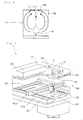
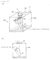
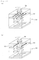
- a powder layer 22 with a predetermined thickness t1 is firstly formed on a base plate for shaped object 21 (see Fig. 1(a) ) and then a predetermined portion of a powder layer 22 is irradiated with a light beam to form a solidified layer 24 on base plate for shaped object 21. Then, a powder layer 22 is newly provided on the solidified layer 24 thus formed and is irradiated again with the light beam to form another solidified layer. In this way, when the solidified layers are repeatedly formed, it is possible to obtain a three-dimensional shaped object with a plurality of solidified layers 24 stacked integrally (see Fig. 1(b) ).
- three-dimensional shaped object is manufactured in a chamber under some inert atmosphere so as to prevent an oxidation of the shaped object.
- a "means for forming a powder layer” and a “forming table at which the powder layer and/or a solidified layer are/is formed” are provided within the chamber.
- a light-beam irradiation means is provided outside the chamber.
- a predetermined portion of the powder layer is irradiated with a light beam from the laser-beam irradiation means through a light transmission window of the chamber.
- the chamber 50 is equipped with the light transmission window 52.
- a light beam L enters the chamber 50 through the light transmission window 52 thereof.
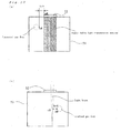
- a smoke-like material called "fume” 8 (e.g., metal vapor or resin vapor) is generated from the light beam-irradiated portion, as shown in Figs. 2(a) and 2(b) .
- the resulting fume moves upward to reach the light transmission window of the chamber, and thereby the fume is attached to the light transmission window, or baked onto such window so that the baked material of the fume is attached thereto (see Fig. 3 ). Therefore, the fume can cause the fogging of the light transmission window, and thereby reducing a transmittance or refractive index of the window for the light beam.
- the reduction of the transmittance or refractive index of the light transmission window for the light beam cannot any more provide the desired solidified layer, which results in an interference with the manufacturing of the intended shaped object.
- the strength of the three-dimensional shaped object will be disadvantageously reduced due to the fact that "sintering process is not stabilized" or "sintering density cannot be increased", for example.
- the fume can directly affect the light beam which enters the chamber. Specifically, the generated fume tends to move upwardly, and thus the upward moving of the fume often obstructs a route for the light beam. This can reduce the amount of irradiation of the light beam (i.e., amount of the light beam applied to the powder layer). As a result, the obstructed route of the light beam, which is attributed to the fume, can reduce the amount of the light beam energy to be applied to the powder layer to a level lower than the predetermined value.
- an object of the present invention is to provide a selective laser sintering method that can suppress the influences of the fume as much as possible.
- the present invention provides a method for manufacturing a three-dimensional shaped object according to appended claim 1.
- fume as used herein means a smoke-like material generated from the powder layer and/or the solidified layer upon being irradiated with the light beam during the manufacturing method of the three-dimensional shaped object.
- the fume can correspond to "metal vapor attributed to the metal powder material” or "resin vapor attributed to the resin powder material”.
- localized gas flow means a local flow of gas, such local flow being formed in a part of an internal space of the chamber.
- the phrase “entrained by the localized gas flow” as used herein substantially means in a broad sense that the fume is carried by the gas flow formed in the interior of the chamber, and whereas such phrase substantially means in a narrow sense that the fume moves such that it is included in the gas flow formed in a part of the internal space of the chamber, and thereby the fume moves along the gas flow.
- the term "powder layer” as used in this description and claims means, for example, "metal powder layer made of a metal powder” or “resin powder layer made of a resin powder”.
- the term "predetermined portion of a powder layer” substantially means a portion of a three-dimensional shaped object to be manufactured. Therefore, a powder existing in such predetermined portion is irradiated with a light beam, whereby the powder undergoes a sintering or a melting and subsequent solidification thereof to form a shape of the three-dimensional shaped object.
- the term “solidified layer” substantially means “sintered layer” when the powder layer is a metal powder layer, whereas it substantially means “cured layer” when the powder layer is a resin powder layer.
- a localized gas flow can be formed at a position away from the light transmission window of the chamber.
- the localized gas flow is formed such that the gas does not flow onto the light transmission window. This makes it possible to prevent the fogging of the light transmission window.
- the localized gas flow is formed at a position away from a route of the light beam entering the chamber so as to prevent the obstructed route of the light beam.
- the localized gas flow can be formed as follows:
- Examples of the embodiment on "localized gas flow" formed within the chamber preferably include the followings:
- the fume entrained by the localized gas flow is discharged from the interior of the chamber. This makes it possible to prevent an overaccumulation of the fume in the interior of the chamber.
- the localized gas flow is provided only at the time of the irradiation of the light beam. This makes it possible to form the localized gas flow only at a point in time when the generation of the fume is occurring, and thereby effectively eliminating the fume.
- the present invention also provides an apparatus according to appended claim 12 for manufacturing a three-dimensional shaped object in which the aforementioned manufacturing method is carried out.
- the fume generated by irradiation of the light beam can be effectively trapped within the chamber.
- the generated fume can be led and confined to a local region in the interior of the chamber, and thus it can be finally discharged from the chamber. This makes it possible to not only prevent the "fogging of the light transmission window of the chamber", but also prevent the "the obstructed route of the light beam by the fume".
- the present invention can prevent a reduction in transmittance of the light beam entering the chamber or prevent a change in refractive index, which leads to an achievement of the formation of the desired solidified layers. More specifically, in a case where the powder layer is a metal powder layer and thus the solidified layer corresponds to a sintered layer, the present invention can avoid such an inconvenience that " the sintering process is not stabilized", "the density of the sintered portion cannot be increased” and the like, which can obtain a substantially uniform strength of the three-dimensional shaped object.
- the selective laser sintering method which will be described, is one where powder material is supplied from a storage tank therefor, followed by being flattened by means of a squeegee blade to form a powder layer therefrom.
- the selective laser sintering method wherein a machining process is additionally is carried out with respect to the shaped object (i.e., the method embodiment shown in Fig. 2(a) , not Fig. 2(b) ) will be described.
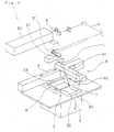
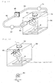
- the laser-sintering/milling hybrid machine 1 is mainly provided with a "powder layer forming means 2 for forming a powder layer by providing a powder such as a metal powder or a resin powder in a predetermined thickness"; a "forming table 20 which is capable of vertically elevating/descending by cylinder drive in a forming tank 29 whose outer periphery is surrounded with a wall 27"; a "base plate for shaped object 21 which is disposed on the forming table 20 and serves as a platform of a shaped object”; a "light-beam irradiation means 3 for irradiating a desired position with an emitted light beam L"; and a “machining means 4 for milling the periphery of a shaped object".
- the powder layer forming means 2 is mainly composed of a "powder table 25 capable of vertically elevating/descending by cylinder drive in a storage tank for powder material 28 whose outer periphery is surrounded with a wall 26" and a "squeegee blade 23 for forming a powder layer 22 on a base plate for shaped obj ect or forming table".
- the light-beam irradiation means 3 is mainly composed of a "light beam generator 30 for emitting a light beam L" and a "galvanometer mirror 31 (scan optical system) for scanning a light beam L onto a powder layer 22".
- the light-beam irradiation means 3 is equipped with a beam shape correcting means for correcting a shape of a light beam spot (e.g., a means composed of a pair of cylindrical lens and a rotation drive mechanism for rotating the lens around a shaft line of the light beam) and f ⁇ lens.
- the machining means 4 is mainly composed of a "milling head 40 for milling the periphery of a shaped object" and an "X-Y actuator 41 (41a, 41b) for driving the milling head 40 to move toward the position to be milled (see Fig. 4 and Fig. 5 ).
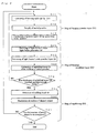
- Fig. 6 shows a general operation flow of a laser-sintering/machining hybrid machine.
- Fig. 7 schematically and simply shows a laser-sintering/machining hybrid process.
- the operations of the laser-sintering/machining hybrid machine are mainly composed of a powder layer forming step (S1) of forming a powder layer 22; a solidified layer forming step (S2) of irradiating the powder layer 22 with a light beam L to form a solidified layer 24; and a machining step (S3) of milling a surface of a shaped object.
- the powder layer forming step (S1) first, the forming table 20 is descended by ⁇ t (S11). Subsequently, a powder table 25 is elevated by ⁇ t1, and thereafter the squeegee blade 23 is driven to move in the direction of arrow "A" as shown in Fig. 1(a) .
- a powder e.g., an "iron powder having a mean particle diameter of about 5 ⁇ m to 100 ⁇ m” or a “powder having a mean particle diameter of about 30 ⁇ m to 100 ⁇ m, such as a powder of nylon, polypropylene or ABS
- a powder placed on the powder table 25 is spread to form a powder layer 22 in a predetermined thickness ⁇ t1 (S13), while being transferred onto the base plate 21 (S12).
- the solidified layer forming step (S2) is performed.
- a light beam L (e.g., carbon dioxide gas laser (500 W), Nd:YAG laser (500 W), fiber laser (500 W) or ultraviolet light) is emitted from the light beam generator 30 (S21) and then a light beam L is scanned onto a desired position of the powder layer 22 by means of the galvanometer mirror 31 (S22).
- the scanned light beam can cause the powder to be melted and solidified, resulting in a formation of the solidified layer 24 integrated with the base plate 21 (S23).
- the light beam may also be transmitted through an optical fiber or the like.
- the powder layer forming step (S1) and the solidified layer forming step (S2) are repeatedly performed until the thickness of the stacked layers 24 reaches such a predetermined value that is obtained based on a tool length of the milling head 40 (see Fig. 1(b) ). Upon a sintering of the powder or a melting and subsequent solidification of the powder, the newly stacked solidified layer is integrated with the lower solidified layer which has already been formed.
- the machining step (S3) is initiated.
- the milling head 40 is actuated to initiate execution of the machining step (S31).
- the milling head 40 is actuated when sixty solidified layers are formed.
- the milling head 40 is moved in X and Y directions by means of the X-Y actuator 41 (41a, 41b) and the shaped object composed of stacked solidified layers 24 is subjected to the surface machining (S32).
- the step returns to the powder layer forming step (S1). Thereafter, the steps S1 through S3 are repeatedly performed to further stack the solidified layers 24, and thereby making it possible to manufacture the desired three-dimensional shaped object (see Fig. 7 ).
- An irradiation path of the light beam L in the solidified layer forming step (S2) and a milling path in the machining step (S3) are determined in advance using 3-D CAD data.
- the machining path is determined by applying contour line processing.
- the contour shape data of each of sliced sections which are regularly-pitched (e.g., 0.05 mm pitch when ⁇ t1 is 0.05 mm) sliced sections of STL data produced from a 3-D CAD model, are used.
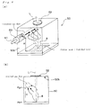
- the present invention is particularly characterized by the process operation associated with the irradiation of the light beam.
- the present invention is characterized in that at least a part of the fume generated by the irradiation of the light beam is entrained by the localized gas flow (see Fig. 8 (a) ).
- Such entrainment of the fume by the localized gas flow can prevent not only the "fogging of the light transmission window of the chamber", but also the "the obstructed route of the light beam by the fume".
- a gas is forced to locally flow in the interior of the chamber to form the localized gas flow. That is, a gas flow is locally formed in a part of a chamber space in which a metal laser-sintering process is performed.
- section size D of the gas flow is preferably in the range of approximately 1 to 100 mm, more preferably in the range of approximately 10 to 50 mm.
- open end size Da of supply nozzle 60 or suction nozzle 70 (which will be described later) see Fig. 9(a) or Fig. 10(a)
- propeller diameter Db of fan see Fig.
- a dynamic pressure in a localized gas flow-forming region becomes higher, then a static pressure of such region correspondingly becomes lower. As a result, the gas around the lowered static pressure region is caused to be drawn into such region, which leads to an entrainment of the fume by the localized gas flow.
- the formation of the localized gas flow is performed for example by supplying a gas into the interior of the chamber 50 from the outside thereof, as shown in Figs. 9(a) and 9(b) .
- a supply nozzle 60 disposed in the wall of the chamber may be used whereby a compressed gas is supplied, as shown in Figs. 9(a) and 9(b) .
- a downstream side of the supply nozzle 60 is in fluid communication with the internal space of the chamber through the wall 50a of the chamber, whereas an upstream side of the supply nozzle 60 is connected to a supply piping 61.
- the supply piping 61 is equipped with a supply pump (not shown in Fig. 9 ).
- the gas can be supplied into the internal space of the chamber by driving the supply pump which is indirectly disposed in the supply nozzle 60.
- the flow rate of the gas to be supplied from the supply nozzle 60 is preferably in the range of approximately 5 to 80 L/min, more preferably in the range of approximately 10 to 60 L/min, still more preferably in the range of approximately 15 to 40 L/min.
- the formation of the localized gas flow can be performed by sucking an atmosphere gas of the chamber from the outside through the wall 50a of the chamber, as shown in Figs. 10(a) and 10(b) .
- a suction nozzle 70 disposed in the wall 50a of the chamber may be used whereby the gas is withdrawn therefrom , as shown in Figs. 10 (a) and 10 (b) .
- an upstream side of the suction nozzle 70 is in fluid communication with the internal space of the chamber through the wall 50a of the chamber, whereas a downstream side of the suction nozzle 70 is connected to a suction piping 71.
- the suction piping 71 is equipped with a suction pump (not shown in Fig. 10 ).
- the localized gas flow can be formed in the interior space of the chamber by driving the suction pump which is indirectly disposed in the suction nozzle 70.
- the flow rate of the gas to be withdrawn from the suction nozzle 70 is preferably in the range of approximately 5 to 80 L/min, more preferably in the range of approximately 10 to 60 L/min, still more preferably in the range of approximately 15 to 40 L/min.
- a combination of the supplying of the gas and the withdrawing of the gas may be used in the present invention.
- "gas supplying through the supply nozzle 60" and “gas withdrawing through the suction nozzle 70” may be performed in parallel, and thereby the localized gas flow is continuously formed while discharging the fume trapped by such gas flow to the outside of the chamber.
- the supply nozzle 60 and the suction nozzle 70 are interconnected via a piping 80 in which a filter 80 is disposed (for example, filter having a function of an electric dust collection may be disposed in the piping 80).
- the withdrawn gas particularly the withdrawn "fume-containing gas" can be treated by such dust-collecting filter 85, and thus the treated gas can be reused as a fresh supply gas.
- the formation of the localized gas flow can be performed by driving a fan 90 disposed in the interior of the chamber 50, as shown in Fig. 12 .
- a rotating of the fan propeller can cause to form the localized gas flow, as shown in Fig. 12 for example.
- the embodiment of driving the fan corresponds to an embodiment wherein a part of an atmosphere gas within the chamber is forced to move, and thus the driving of the fan is performed under a condition of the closed system (in contrast, the embodiments of Figs. 9 and 10 are involved in "gas movement from the outside of the chamber to the inside thereof" or "gas movement from the inside of the chamber to the outside thereof").
- the number of the rotation of the fan propeller (as shown in Fig. 12 ), which is not limited to specific one as long as the entrainment of the fume by the gas flow is caused, may be for example in the range of approximately 50 to 300 rpm.
- the embodiment of the localized gas flow to be formed in the interior of the chamber is not limited to specific one as long as the "fogging of the light transmission window of the chamber by the fume" or "obstructed route of the light beam by the fume" is prevented and it is according to the appended claims.
- the localized gas flow is formed at a position away from the light transmission window of the chamber.
- the localized gas flow is preferably formed in the interior space of the chamber except for the region located below the light transmission window 52.
- the horizontal position of the localized gas flow is off the position of the light transmission window 52. This will be described in detail with reference to Fig. 13 (a) .
- the localized gas flow is provided such that a horizontal length L a-b between the edge (point "a") of the light transmission window and the lateral side (point "b") of the localized gas flow is at least about 1mm.
- the upper limit of the horizontal length L a-b which varies depending on the chamber size or the like, may be about 100 mm for example.
- the positioning of the localized gas flow away from the light transmission window makes it possible to effectively prevent the fogging of such window.
- the localized gas flow is formed at a position away form the light beam route.
- the localized gas flow is formed to be horizontally off the route of the light beam entering the chamber. This will be described in detail with reference to Fig. 13(b) .
- the localized gas flow is provided such that a horizontal length L c-d between the edge portion (point "c") of the light beam and the lateral side (point "d") of the localized gas flow is at least about 1mm.
- the upper limit of the horizontal length L c-d which varies depending on the chamber size or the like, may be about 100 mm for example.
- the positioning of the localized gas flow away from the light beam route makes it possible to effectively prevent the "obstructed route of the light beam by the fume".
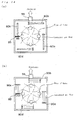
- the position of the localized gas flow is off the light transmission window or light beam route and the localized gas flow may be formed along an inner wall surface of the chamber. It is preferred in this case that the localized gas flow is formed in the vicinity of the inner wall surface of the chamber such that the gas circulates along the inner wall surface of the chamber, as shown in Figs. 14 and 15 .
- This makes it possible to keep the fume trapped in the localized gas flow in the vicinity of the inner wall surface of the chamber. In other words, since the generated fume can be kept in the peripheral region of the internal space of the chamber for a certain period of time, the metal laser-sintering process can be stably performed.
- a circling flow along the inner wall surface of the chamber is formed as the localized gas flow, and thus the circling flow is positioned off the light transmission window or light beam route. Accordingly, the fume is entrained by the circling flow to be off the light transmission window or light beam route, and thereby the fogging of the window and the damping of the light beam are effectively prevented.
- a plurality of gas nozzles may be disposed in vicinity of the inner wall surface of the chamber (see Fig. 14(a) ) or a plurality of fans (90a, 90b, 90c, 90d) may be disposed in vicinity of the inner wall surface of the chamber (see Fig. 14(b) ) so that a unidirectional circling or rotating of the gas flow is formed. It is preferred that one of the gas nozzles (60a, 60b, 60c, 60d) or fans (90a, 90b, 90c, 90d) is disposed near each of the inner wall surfaces of the chamber as shown in Figs.
- a filter 85 may be disposed in the orbit of the circling gas flow, as shown in Figs. 14 (a) , 14(b) and 15(a) .
- the fume-containing gas can be in this case treated by such dust-collecting filter 85, and thereby keeping the circling of the gas flow for a relatively long period of time.
- the localized gas flow is formed away from the powder layer at least by 10 mm or larger so as not to upwardly entrain the powder of the powder layer by such gas flow.
- the effective prevention of the upward entrainment of the powder makes it possible to facilitate the desired formation of the solidified layer.
- the length "H" shown in Figs. 9(a) and 9(b) is preferably 10 mm or larger.
- the lower limit of the length between "surface level Ha of the powder layer and/or solidified layer" and "Hb of lower edge portion of the gas flow" is preferably 10 mm.
- the localized gas flow may be provided in the vicinity of the upper wall's inner surface ("50b" in Fig. 9(b) ) of the chamber.
- the localized gas flow may be formed in a planar form. That is, as shown in the example of Fig. 16 (a) (not according to the invention), the localized gas is forced to flow in the planar or parallel form so that a curtain 101 of the gas flow is formed. This makes it possible to entrain the fume generated from every point of the powder layer to the gas flow. As a result, the influence attributed to the difference among the fume-generating points can be reduced. From a practical point of view according to present invention, the curtain 101 of the gas flow is formed in the interior space of the chamber except for the region located below the light transmission window 52 so as not to obstruct the route of the light beam (see Fig. 16(b) ).
- the formation of the curtain 101 made of the localized gas flow can be performed by modifying the gas supply nozzle 60 shown in Fig. 9(a) into "gas supply nozzle with slit-like opening".
- the formation of the curtain can be alternatively performed by supplying the gas in parallel by means of a plurality of the horizontally arranged "gas supply nozzles 60 (shown in Fig. 9(a) )".
- the kind of the gas used for the localized gas flow there is no particular limitation to the kind of the gas used for the localized gas flow, and thus various kinds of gas can be used.
- the gas which is the same as the atmosphere gas filled in the chamber may be used. From a cost standpoint, "air" is preferably used.
- an inert gas e.g., nitrogen gas
- nitrogen gas is preferably used.
- the fume entrained by the localized gas flow may be discharged as necessary from the interior of the chamber.
- the entrained fume may be discharged from a discharge port 55 at a point in time when the amount of the accumulated fume by the gas flow reaches a certain level.
- Such discharge may be performed by forcibly performing a sucking operation, or by simply opening the port 55 which serves to form the closed system.
- the internal pressure of the chamber shows a gradual increase with a continuous supplying of the gas, and thus the accumulated fume may be discharged simply by opening the closed discharge port.
- the localized gas flow may be generated only at the time of the irradiation of the light beam. That is, the supplying of the gas (see Fig. 9 ), the withdrawing of the gas ( Fig. 10 ) and the driving of the fan (see Fig. 12 ) may be performed only at a point in time when the irradiation of the light beam is performing. This makes it possible to form the localized gas flow in synchronization with the generation of the fume, which leads to a lower running cost (i.e., lower cost of operation).
- the synchronized flow of the gas with the fume generation can be formed through outputting "data of irradiation time to be output to the light beam generator" to a gas supply pump (in a case of Fig. 9 ), a gas suction pump (in a case of Fig. 10 ) or a driving part of fan (in a case of Fig. 12 ).
- such a device includes a powder layer forming means 2 for forming a metal powder layer; a light-beam irradiation means 3 for irradiating the metal powder layer with a light beam so as to form a sintered layer; a forming table 20 at which the metal powder layer and/or sintered layer are/is formed; and a chamber 50 in which the metal powder layer forming means and the forming table are disposed.
- the device further comprises a gas flow means for forming a localized gas flow in the chamber 50 as defined in appended claim 12.
- the "powder layer forming means 2", the "forming table 20", the "light-beam irradiation means 3" and the "chamber 50" in addition to the operation of the above device have been already described in the above paragraphs regarding the "Selective Laser Sintering Method", and therefore a repeated description thereof will be omitted.
- the gas flow means the supply nozzle 60 (and supply pump) as shown in Fig. 9 , the suction nozzle 70 (and suction pump) as shown in Fig. 10 , the fan 90 (and driving unit therefor) as shown in Fig. 12 may be available.
- the number of the gas flow means is not limited to "one" (single), and thus a plurality of the gas flow means may be used as appropriate.
- JP-T-09-511693 will be briefly described below, which is essentially different from the present invention in terms of technical idea.
- JP-T-09-511693 discloses a "device for manufacturing a layered object by using a laser sintering process".
- the disclosed device of JP-T-09-511693 allows a nitrogen gas to flow toward a lens for focusing a beam.
- the disclosed device takes various measures so that the gas flows along the whole surface of the lens. Note that the above publication neither discloses nor suggests the technical idea "entrainment by localized gas flow" of the present invention.
- the method and apparatus for manufacturing a three-dimensional shaped object according to present invention can produce various kinds of objects.
- the powder layer is a metal powder layer (inorganic powder layer) and thus the solidified layer corresponds to a sintered layer
- the produced three-dimensional shaped object can be used as a metal mold for a plastic injection molding, a press molding, a die casting, a casting or a forging.
- the produced three-dimensional shaped object can be used as a resin molded article.
Landscapes
- Engineering & Computer Science (AREA)
- Chemical & Material Sciences (AREA)
- Materials Engineering (AREA)
- Manufacturing & Machinery (AREA)
- Physics & Mathematics (AREA)
- Optics & Photonics (AREA)
- Mechanical Engineering (AREA)
- Plasma & Fusion (AREA)
- Powder Metallurgy (AREA)
Applications Claiming Priority (2)
| Application Number | Priority Date | Filing Date | Title |
|---|---|---|---|
| JP2009242685 | 2009-10-21 | ||
| PCT/JP2010/068521 WO2011049143A1 (ja) | 2009-10-21 | 2010-10-20 | 三次元形状造形物の製造方法およびその製造装置 |
Publications (3)
| Publication Number | Publication Date |
|---|---|
| EP2492084A1 EP2492084A1 (en) | 2012-08-29 |
| EP2492084A4 EP2492084A4 (en) | 2012-12-12 |
| EP2492084B1 true EP2492084B1 (en) | 2015-05-13 |
Family
ID=43900366
Family Applications (1)
| Application Number | Title | Priority Date | Filing Date |
|---|---|---|---|
| EP10824992.1A Not-in-force EP2492084B1 (en) | 2009-10-21 | 2010-10-20 | Process for producing three-dimensionally shaped object and device for producing same |
Country Status (5)
| Country | Link |
|---|---|
| US (1) | US9073264B2 (zh) |
| EP (1) | EP2492084B1 (zh) |
| JP (1) | JP5653358B2 (zh) |
| CN (2) | CN102574333B (zh) |
| WO (1) | WO2011049143A1 (zh) |
Families Citing this family (81)
| Publication number | Priority date | Publication date | Assignee | Title |
|---|---|---|---|---|
| DE112011100572T5 (de) | 2010-02-17 | 2012-11-29 | Panasonic Corporation | Verfahren zum herstellen eines dreidimensionalen formgegenstands und dreidimensionaler formgegenstand |
| JP5584019B2 (ja) | 2010-06-09 | 2014-09-03 | パナソニック株式会社 | 三次元形状造形物の製造方法およびそれから得られる三次元形状造形物 |
| DE102011085154A1 (de) * | 2011-10-25 | 2013-04-25 | Evonik Industries Ag | Vorrichtung zur Vermeidung von Ablagerungen an optischen Komponenten im Laser-Sintern |
| CN102528034B (zh) * | 2012-02-24 | 2016-05-04 | 湖南华曙高科技有限责任公司 | 一种选择性激光烧结窗口镜气帘保护方法 |
| US9687911B2 (en) | 2012-03-09 | 2017-06-27 | Panasonic Intellectual Property Management Co., Ltd. | Method for manufacturing three-dimensional shaped object |
| JP2019163547A (ja) * | 2013-02-14 | 2019-09-26 | レニショウ パブリック リミテッド カンパニーRenishaw Public Limited Company | 選択的レーザ固化装置及び方法 |
| EP3566798A1 (en) | 2013-02-14 | 2019-11-13 | Renishaw PLC | Selective laser solidification apparatus and method |
| US9267189B2 (en) * | 2013-03-13 | 2016-02-23 | Honeywell International Inc. | Methods for forming dispersion-strengthened aluminum alloys |
| US9669583B2 (en) | 2013-03-15 | 2017-06-06 | Renishaw Plc | Selective laser solidification apparatus and method |
| DE102013205724A1 (de) | 2013-03-28 | 2014-10-02 | Eos Gmbh Electro Optical Systems | Verfahren und Vorrichtung zum Herstellen eines dreidimensionalen Objekts |
| EP3782798B1 (en) | 2013-04-03 | 2022-03-09 | SLM Solutions Group AG | Method and apparatus for producing three-dimensional work pieces |
| CN109177153B (zh) * | 2013-06-10 | 2021-03-30 | 瑞尼斯豪公司 | 选择性激光固化设备和方法 |
| GB201310398D0 (en) | 2013-06-11 | 2013-07-24 | Renishaw Plc | Additive manufacturing apparatus and method |
| US10518325B2 (en) | 2013-06-20 | 2019-12-31 | MTU Aero Engines AG | Device and method for additively producing at least one component region of a component |
| JP5599921B1 (ja) | 2013-07-10 | 2014-10-01 | パナソニック株式会社 | 三次元形状造形物の製造方法 |
| JP5612735B1 (ja) * | 2013-07-10 | 2014-10-22 | パナソニック株式会社 | 三次元形状造形物の製造方法およびその製造装置 |
| DE102013011676A1 (de) * | 2013-07-11 | 2015-01-15 | Fraunhofer-Gesellschaft zur Förderung der angewandten Forschung e.V. | Vorrichtung und Verfahren zur generativen Bauteilfertigung |
| EP2862651B1 (en) | 2013-10-15 | 2019-07-17 | SLM Solutions Group AG | Method and apparatus for producing a large three-dimensional work piece |
| FR3014355B1 (fr) * | 2013-12-11 | 2016-02-05 | Essilor Int | Procede de fabrication d'une lentille ophtalmique |
| JP5908516B2 (ja) * | 2014-03-18 | 2016-04-26 | 株式会社東芝 | 積層造形装置用のノズルおよび積層造形装置 |
| DE102014205875A1 (de) * | 2014-03-28 | 2015-10-01 | Eos Gmbh Electro Optical Systems | Vorrichtung und Verfahren zum schichtweisen Herstellen eines dreidimensionalen Objekts |
| GB201410484D0 (en) * | 2014-06-12 | 2014-07-30 | Renishaw Plc | Additive manufacturing apparatus and a flow device for use with such apparatus |
| JP5721886B1 (ja) * | 2014-06-20 | 2015-05-20 | 株式会社ソディック | 積層造形装置 |
| JP5721887B1 (ja) * | 2014-06-20 | 2015-05-20 | 株式会社ソディック | 積層造形装置 |
| MX355451B (es) | 2014-06-20 | 2018-04-18 | Velo3D Inc | Aparatos, sistemas y metodos para impresion tridimensional. |
| EP2974813A1 (de) | 2014-07-17 | 2016-01-20 | MTU Aero Engines GmbH | Anlage und verfahren zur generativen herstellung und/oder reparatur von bauteilen |
| US10413970B2 (en) | 2014-07-30 | 2019-09-17 | Panasonic Intellectual Property Management Co., Ltd. | Method for manufacturing three-dimensional shaped object and three-dimensional shaped object |
| DE102014217786A1 (de) | 2014-09-05 | 2016-03-10 | Eos Gmbh Electro Optical Systems | Verfahren, Vorrichtung und Steuereinheit zum Herstellen eines dreidimensionalen Objekts |
| EP3015197B1 (de) * | 2014-10-30 | 2017-03-08 | MTU Aero Engines GmbH | Vorrichtung zur Herstellung oder Reparatur eines dreidimensionalen Objekts |
| US11458539B2 (en) * | 2014-11-24 | 2022-10-04 | Additive Industries B.V. | Apparatus for producing an object by means of additive manufacturing |
| EP3023228B1 (en) * | 2014-11-24 | 2018-08-08 | Trumpf Sisma S.r.l. | Gas flow within additive manufacturing device |
| US20170341143A1 (en) * | 2014-12-26 | 2017-11-30 | Panasonic Intellectual Property Management Co., Ltd. | Method for manufacturing three-dimensional shaped object |
| TW201630675A (zh) * | 2015-02-16 | 2016-09-01 | Excetek Technologies Co Ltd | 金屬積層與放電加工複合設備 |
| GB201505458D0 (en) | 2015-03-30 | 2015-05-13 | Renishaw Plc | Additive manufacturing apparatus and methods |
| JP5960330B1 (ja) | 2015-07-13 | 2016-08-02 | 株式会社ソディック | 積層造形装置 |
| CN107921659A (zh) * | 2015-07-23 | 2018-04-17 | 瑞尼斯豪公司 | 增材制造设备和用于此类设备的气体流动装置 |
| CN104959605B (zh) * | 2015-07-27 | 2017-10-10 | 中南大学 | 一种制备镁合金人工骨的激光选区熔覆设备 |
| GB201517188D0 (en) * | 2015-09-29 | 2015-11-11 | Renishaw Plc | Additive manufacturing apparatus and methods |
| JP6642790B2 (ja) * | 2015-10-15 | 2020-02-12 | セイコーエプソン株式会社 | 三次元造形物の製造方法及び三次元造形物の製造装置 |
| IL287642B (en) | 2015-10-30 | 2022-07-01 | Seurat Tech Inc | Add-on and device creation system |
| WO2017079091A1 (en) | 2015-11-06 | 2017-05-11 | Velo3D, Inc. | Adept three-dimensional printing |
| CN108698126A (zh) | 2015-12-10 | 2018-10-23 | 维洛3D公司 | 精湛的三维打印 |
| CN108883575A (zh) | 2016-02-18 | 2018-11-23 | 维洛3D公司 | 准确的三维打印 |
| WO2017196323A1 (en) * | 2016-05-12 | 2017-11-16 | Hewlett-Packard Development Company, L.P. | Airflow component |
| JP6234596B1 (ja) * | 2016-05-31 | 2017-11-22 | 技術研究組合次世代3D積層造形技術総合開発機構 | 3次元積層造形システム、3次元積層造形方法、積層造形制御装置およびその制御方法と制御プログラム |
| US11691343B2 (en) | 2016-06-29 | 2023-07-04 | Velo3D, Inc. | Three-dimensional printing and three-dimensional printers |
| EP3492244A1 (en) | 2016-06-29 | 2019-06-05 | VELO3D, Inc. | Three-dimensional printing system and method for three-dimensional printing |
| JP6026698B1 (ja) | 2016-07-13 | 2016-11-16 | 株式会社松浦機械製作所 | 三次元造形装置 |
| EP3292927A1 (en) * | 2016-09-13 | 2018-03-14 | Linde Aktiengesellschaft | Method for additive manufacturing |
| US20180126650A1 (en) | 2016-11-07 | 2018-05-10 | Velo3D, Inc. | Gas flow in three-dimensional printing |
| CN106735197B (zh) * | 2016-11-10 | 2019-08-27 | 湖南华曙高科技有限责任公司 | 用于制造三维物体的设备及其移动式除烟装置 |
| JP2018103462A (ja) * | 2016-12-26 | 2018-07-05 | ナブテスコ株式会社 | 造形装置 |
| WO2018129089A1 (en) | 2017-01-05 | 2018-07-12 | Velo3D, Inc. | Optics in three-dimensional printing |
| US20180250745A1 (en) | 2017-03-02 | 2018-09-06 | Velo3D, Inc. | Three-dimensional printing of three-dimensional objects |
| DE102017104351A1 (de) | 2017-03-02 | 2018-09-06 | Cl Schutzrechtsverwaltungs Gmbh | Vorrichtung zur additiven Herstellung dreidimensionaler Objekte |
| EP3378584B1 (en) * | 2017-03-24 | 2021-10-27 | SLM Solutions Group AG | Device and method for producing a three-dimensional workpiece |
| US20180281282A1 (en) | 2017-03-28 | 2018-10-04 | Velo3D, Inc. | Material manipulation in three-dimensional printing |
| EP3603853A4 (en) * | 2017-03-31 | 2020-12-23 | Nikon Corporation | MODELING SYSTEM AND MODELING PROCESS |
| DE102017215911A1 (de) * | 2017-09-08 | 2019-03-14 | Sauer Gmbh | Laser-Werkzeugmaschine mit Absaugsystem |
| DE102017122849A1 (de) | 2017-10-02 | 2019-04-04 | Stefan Fischer | Fluidversorgungssystem für einen 3D-Drucker |
| US20190099943A1 (en) * | 2017-10-03 | 2019-04-04 | General Electric Company | Additive manufacturing method and apparatus |
| TWI661927B (zh) * | 2017-10-12 | 2019-06-11 | 國家中山科學研究院 | 積層製造腔體 |
| US20190111621A1 (en) * | 2017-10-18 | 2019-04-18 | General Electric Company | Additive manufacturing apparatus |
| EP3473442B1 (en) * | 2017-10-20 | 2021-03-03 | CL Schutzrechtsverwaltungs GmbH | Apparatus for additively manufacturing of three-dimensional objects |
| JP6445113B2 (ja) * | 2017-10-24 | 2018-12-26 | 技術研究組合次世代3D積層造形技術総合開発機構 | 3次元積層造形システム、3次元積層造形方法、積層造形制御装置およびその制御方法と制御プログラム |
| JP7107661B2 (ja) * | 2017-10-31 | 2022-07-27 | 三菱重工業株式会社 | 積層造形用ノズル、及び積層造形装置 |
| WO2019124115A1 (ja) * | 2017-12-18 | 2019-06-27 | 本田技研工業株式会社 | 3次元造形装置 |
| US10272525B1 (en) * | 2017-12-27 | 2019-04-30 | Velo3D, Inc. | Three-dimensional printing systems and methods of their use |
| US10144176B1 (en) | 2018-01-15 | 2018-12-04 | Velo3D, Inc. | Three-dimensional printing systems and methods of their use |
| EP3539754B1 (en) | 2018-03-14 | 2023-04-26 | Concept Laser GmbH | Method for additively manufacturing at least one three-dimensional object |
| EP3560715B1 (en) | 2018-04-26 | 2021-07-07 | Nabtesco Corporation | Modeling apparatus |
| JP2019209646A (ja) | 2018-06-07 | 2019-12-12 | ナブテスコ株式会社 | 造形装置 |
| EP3599079B1 (en) * | 2018-07-25 | 2023-01-04 | Concept Laser GmbH | Apparatus for additively manufacturing three-dimensional objects |
| WO2020033310A1 (en) | 2018-08-06 | 2020-02-13 | Vulcanforms Inc. | Additive manufacturing system with gas flow head |
| EP3670150B1 (en) * | 2018-12-20 | 2024-05-29 | Concept Laser GmbH | Method for handling build material for an apparatus for additively manufacturing three-dimensional objects |
| US11745289B2 (en) | 2019-02-21 | 2023-09-05 | General Electric Company | Additive manufacturing systems and methods including rotating build platform |
| JP6745945B1 (ja) * | 2019-05-15 | 2020-08-26 | Dmg森精機株式会社 | 加工機械 |
| JP7130596B2 (ja) * | 2019-05-21 | 2022-09-05 | 株式会社荏原製作所 | 造形物を製造するためのam装置およびam装置におけるビームの照射位置を試験する方法 |
| JP6653909B1 (ja) * | 2019-07-03 | 2020-02-26 | 株式会社松浦機械製作所 | 三次元造形物の製造方法 |
| JP6871315B2 (ja) * | 2019-07-24 | 2021-05-12 | 株式会社ソディック | 積層造形装置および三次元造形物の製造方法 |
| WO2023117053A1 (en) | 2021-12-21 | 2023-06-29 | S&S Scheftner Gmbh | 3d printer with protruding structure for generating a gas curtain |
Family Cites Families (20)
| Publication number | Priority date | Publication date | Assignee | Title |
|---|---|---|---|---|
| EP0287657B2 (en) | 1986-10-17 | 1999-08-11 | Board Of Regents, The University Of Texas System | Method and apparatus for producing parts by selective sintering |
| AU9065991A (en) | 1990-11-09 | 1992-06-11 | Dtm Corporation | Controlled gas flow for selective laser sintering |
| DE29513026U1 (de) | 1995-08-16 | 1995-10-05 | Eos Electro Optical Syst | Vorrichtung zur schichtweisen Herstellung eines Objektes mittels Lasersintern |
| US5870663A (en) | 1996-08-02 | 1999-02-09 | The Texas A&M University System | Manufacture and use of ZrB2 /CU composite electrodes |
| JP3446618B2 (ja) | 1998-08-26 | 2003-09-16 | 松下電工株式会社 | 金属粉末焼結部品の表面仕上げ方法 |
| JP3943315B2 (ja) * | 2000-07-24 | 2007-07-11 | 松下電工株式会社 | 三次元形状造形物の製造方法 |
| TW506868B (en) | 2000-10-05 | 2002-10-21 | Matsushita Electric Works Ltd | Method of and apparatus for making a three-dimensional object |
| DE10344902B4 (de) | 2002-09-30 | 2009-02-26 | Matsushita Electric Works, Ltd., Kadoma | Verfahren zum Herstellen eines dreidimensionalen Objekts |
| US8062020B2 (en) | 2003-02-25 | 2011-11-22 | Panasonic Electric Works Co., Ltd. | Three dimensional structure producing device and producing method |
| JP2004277878A (ja) * | 2003-02-25 | 2004-10-07 | Matsushita Electric Works Ltd | 三次元形状造形物の製造装置及び製造方法 |
| JP4130813B2 (ja) | 2004-05-26 | 2008-08-06 | 松下電工株式会社 | 三次元形状造形物の製造装置及びその光ビーム照射位置及び加工位置の補正方法 |
| JP4131260B2 (ja) * | 2004-10-26 | 2008-08-13 | 松下電工株式会社 | 三次元形状造形物の製造装置 |
| DE102006014835A1 (de) * | 2006-03-30 | 2007-10-04 | Fockele, Matthias, Dr. | Vorrichtung zur Herstellung von Gegenständen durch schichtweises Aufbauen aus pulverförmigem Werkstoff |
| KR100925363B1 (ko) | 2007-05-30 | 2009-11-09 | 파나소닉 전공 주식회사 | 적층 조형 장치 |
| JP4258567B1 (ja) | 2007-10-26 | 2009-04-30 | パナソニック電工株式会社 | 三次元形状造形物の製造方法 |
| JP5301217B2 (ja) | 2008-08-22 | 2013-09-25 | パナソニック株式会社 | 三次元形状造形物の製造方法およびその製造装置 |
| JP5250338B2 (ja) | 2008-08-22 | 2013-07-31 | パナソニック株式会社 | 三次元形状造形物の製造方法、その製造装置および三次元形状造形物 |
| US8738166B2 (en) | 2009-02-24 | 2014-05-27 | Panasonic Corporation | Method for manufacturing three-dimensional shaped object and three-dimensional shaped object obtained by the same |
| JP5364439B2 (ja) | 2009-05-15 | 2013-12-11 | パナソニック株式会社 | 三次元形状造形物の製造方法 |
| DE112010002686T5 (de) | 2009-06-23 | 2013-01-03 | Panasonic Corporation | Verfahren zur Herstellung eines dreidimensionalen Formgegenstands und mit diesem Verfahren hergestellter dreidimensionaler Formgegenstand |
-
2010
- 2010-10-20 US US13/503,217 patent/US9073264B2/en not_active Expired - Fee Related
- 2010-10-20 CN CN201080047421.XA patent/CN102574333B/zh not_active Expired - Fee Related
- 2010-10-20 CN CN201510090105.5A patent/CN104741608B/zh not_active Expired - Fee Related
- 2010-10-20 JP JP2011537290A patent/JP5653358B2/ja active Active
- 2010-10-20 EP EP10824992.1A patent/EP2492084B1/en not_active Not-in-force
- 2010-10-20 WO PCT/JP2010/068521 patent/WO2011049143A1/ja active Application Filing
Also Published As
| Publication number | Publication date |
|---|---|
| CN102574333A (zh) | 2012-07-11 |
| EP2492084A1 (en) | 2012-08-29 |
| EP2492084A4 (en) | 2012-12-12 |
| CN104741608B (zh) | 2017-07-28 |
| US20120251378A1 (en) | 2012-10-04 |
| CN102574333B (zh) | 2015-07-29 |
| US9073264B2 (en) | 2015-07-07 |
| JPWO2011049143A1 (ja) | 2013-03-14 |
| CN104741608A (zh) | 2015-07-01 |
| WO2011049143A1 (ja) | 2011-04-28 |
| JP5653358B2 (ja) | 2015-01-14 |
Similar Documents
| Publication | Publication Date | Title |
|---|---|---|
| EP2492084B1 (en) | Process for producing three-dimensionally shaped object and device for producing same | |
| JP5250338B2 (ja) | 三次元形状造形物の製造方法、その製造装置および三次元形状造形物 | |
| US9005513B2 (en) | Layered-modeling method for manufacturing three-dimensional object | |
| US20170341143A1 (en) | Method for manufacturing three-dimensional shaped object | |
| EP2902137B1 (en) | Method for manufacturing a three-dimensional object | |
| JP5272871B2 (ja) | 積層造形装置 | |
| JP4131260B2 (ja) | 三次元形状造形物の製造装置 | |
| JP5027780B2 (ja) | 積層造形装置 | |
| US9687911B2 (en) | Method for manufacturing three-dimensional shaped object | |
| US8999222B2 (en) | Method for manufacturing three-dimensionally shaped object, three-dimensionally shaped object obtained thereby, and method for manufacturing molded article | |
| JP5764751B2 (ja) | 三次元形状造形物の製造方法およびその製造装置 | |
| US20140010908A1 (en) | Method for manufacturing three-dimensional shaped object and three-dimensional shaped object | |
| JP5456400B2 (ja) | 三次元形状造形物の製造装置および製造方法 | |
| JP2010132961A (ja) | 積層造形装置及び積層造形方法 | |
| JP6192677B2 (ja) | 積層造形方法および積層造形装置 |
Legal Events
| Date | Code | Title | Description |
|---|---|---|---|
| PUAI | Public reference made under article 153(3) epc to a published international application that has entered the european phase |
Free format text: ORIGINAL CODE: 0009012 |
|
| 17P | Request for examination filed |
Effective date: 20120427 |
|
| AK | Designated contracting states |
Kind code of ref document: A1 Designated state(s): AL AT BE BG CH CY CZ DE DK EE ES FI FR GB GR HR HU IE IS IT LI LT LU LV MC MK MT NL NO PL PT RO RS SE SI SK SM TR |
|
| A4 | Supplementary search report drawn up and despatched |
Effective date: 20121109 |
|
| RIC1 | Information provided on ipc code assigned before grant |
Ipc: B22F 3/105 20060101ALI20121105BHEP Ipc: B22F 3/16 20060101ALI20121105BHEP Ipc: B29C 67/00 20060101AFI20121105BHEP |
|
| DAX | Request for extension of the european patent (deleted) | ||
| GRAP | Despatch of communication of intention to grant a patent |
Free format text: ORIGINAL CODE: EPIDOSNIGR1 |
|
| INTG | Intention to grant announced |
Effective date: 20141205 |
|
| GRAS | Grant fee paid |
Free format text: ORIGINAL CODE: EPIDOSNIGR3 |
|
| GRAA | (expected) grant |
Free format text: ORIGINAL CODE: 0009210 |
|
| AK | Designated contracting states |
Kind code of ref document: B1 Designated state(s): AL AT BE BG CH CY CZ DE DK EE ES FI FR GB GR HR HU IE IS IT LI LT LU LV MC MK MT NL NO PL PT RO RS SE SI SK SM TR |
|
| REG | Reference to a national code |
Ref country code: GB Ref legal event code: FG4D |
|
| RIN1 | Information on inventor provided before grant (corrected) |
Inventor name: HIGASHI, YOSHIKAZU PANASONIC INTELLECTUAL PROP. MA Inventor name: FUWA, ISAO PANASONIC INTELLECTUAL PROP. MANAGEMENT Inventor name: YOSHIDA, NORIO PANASONIC INTELLECTUAL PROP. MANAGE Inventor name: ABE, SATOSHI PANASONIC INTELLECTUAL PROP. MANAGEME |
|
| REG | Reference to a national code |
Ref country code: CH Ref legal event code: EP |
|
| REG | Reference to a national code |
Ref country code: IE Ref legal event code: FG4D |
|
| REG | Reference to a national code |
Ref country code: AT Ref legal event code: REF Ref document number: 726661 Country of ref document: AT Kind code of ref document: T Effective date: 20150615 |
|
| REG | Reference to a national code |
Ref country code: DE Ref legal event code: R096 Ref document number: 602010024682 Country of ref document: DE Effective date: 20150625 |
|
| REG | Reference to a national code |
Ref country code: AT Ref legal event code: MK05 Ref document number: 726661 Country of ref document: AT Kind code of ref document: T Effective date: 20150513 |
|
| REG | Reference to a national code |
Ref country code: NL Ref legal event code: MP Effective date: 20150513 |
|
| REG | Reference to a national code |
Ref country code: LT Ref legal event code: MG4D |
|
| PG25 | Lapsed in a contracting state [announced via postgrant information from national office to epo] |
Ref country code: PT Free format text: LAPSE BECAUSE OF FAILURE TO SUBMIT A TRANSLATION OF THE DESCRIPTION OR TO PAY THE FEE WITHIN THE PRESCRIBED TIME-LIMIT Effective date: 20150914 Ref country code: NO Free format text: LAPSE BECAUSE OF FAILURE TO SUBMIT A TRANSLATION OF THE DESCRIPTION OR TO PAY THE FEE WITHIN THE PRESCRIBED TIME-LIMIT Effective date: 20150813 Ref country code: FI Free format text: LAPSE BECAUSE OF FAILURE TO SUBMIT A TRANSLATION OF THE DESCRIPTION OR TO PAY THE FEE WITHIN THE PRESCRIBED TIME-LIMIT Effective date: 20150513 Ref country code: LT Free format text: LAPSE BECAUSE OF FAILURE TO SUBMIT A TRANSLATION OF THE DESCRIPTION OR TO PAY THE FEE WITHIN THE PRESCRIBED TIME-LIMIT Effective date: 20150513 Ref country code: ES Free format text: LAPSE BECAUSE OF FAILURE TO SUBMIT A TRANSLATION OF THE DESCRIPTION OR TO PAY THE FEE WITHIN THE PRESCRIBED TIME-LIMIT Effective date: 20150513 Ref country code: HR Free format text: LAPSE BECAUSE OF FAILURE TO SUBMIT A TRANSLATION OF THE DESCRIPTION OR TO PAY THE FEE WITHIN THE PRESCRIBED TIME-LIMIT Effective date: 20150513 |
|
| PG25 | Lapsed in a contracting state [announced via postgrant information from national office to epo] |
Ref country code: GR Free format text: LAPSE BECAUSE OF FAILURE TO SUBMIT A TRANSLATION OF THE DESCRIPTION OR TO PAY THE FEE WITHIN THE PRESCRIBED TIME-LIMIT Effective date: 20150814 Ref country code: BG Free format text: LAPSE BECAUSE OF FAILURE TO SUBMIT A TRANSLATION OF THE DESCRIPTION OR TO PAY THE FEE WITHIN THE PRESCRIBED TIME-LIMIT Effective date: 20150813 Ref country code: AT Free format text: LAPSE BECAUSE OF FAILURE TO SUBMIT A TRANSLATION OF THE DESCRIPTION OR TO PAY THE FEE WITHIN THE PRESCRIBED TIME-LIMIT Effective date: 20150513 Ref country code: LV Free format text: LAPSE BECAUSE OF FAILURE TO SUBMIT A TRANSLATION OF THE DESCRIPTION OR TO PAY THE FEE WITHIN THE PRESCRIBED TIME-LIMIT Effective date: 20150513 Ref country code: IS Free format text: LAPSE BECAUSE OF FAILURE TO SUBMIT A TRANSLATION OF THE DESCRIPTION OR TO PAY THE FEE WITHIN THE PRESCRIBED TIME-LIMIT Effective date: 20150913 Ref country code: RS Free format text: LAPSE BECAUSE OF FAILURE TO SUBMIT A TRANSLATION OF THE DESCRIPTION OR TO PAY THE FEE WITHIN THE PRESCRIBED TIME-LIMIT Effective date: 20150513 |
|
| PG25 | Lapsed in a contracting state [announced via postgrant information from national office to epo] |
Ref country code: EE Free format text: LAPSE BECAUSE OF FAILURE TO SUBMIT A TRANSLATION OF THE DESCRIPTION OR TO PAY THE FEE WITHIN THE PRESCRIBED TIME-LIMIT Effective date: 20150513 Ref country code: DK Free format text: LAPSE BECAUSE OF FAILURE TO SUBMIT A TRANSLATION OF THE DESCRIPTION OR TO PAY THE FEE WITHIN THE PRESCRIBED TIME-LIMIT Effective date: 20150513 |
|
| REG | Reference to a national code |
Ref country code: DE Ref legal event code: R097 Ref document number: 602010024682 Country of ref document: DE |
|
| PG25 | Lapsed in a contracting state [announced via postgrant information from national office to epo] |
Ref country code: CZ Free format text: LAPSE BECAUSE OF FAILURE TO SUBMIT A TRANSLATION OF THE DESCRIPTION OR TO PAY THE FEE WITHIN THE PRESCRIBED TIME-LIMIT Effective date: 20150513 Ref country code: SK Free format text: LAPSE BECAUSE OF FAILURE TO SUBMIT A TRANSLATION OF THE DESCRIPTION OR TO PAY THE FEE WITHIN THE PRESCRIBED TIME-LIMIT Effective date: 20150513 Ref country code: RO Free format text: LAPSE BECAUSE OF NON-PAYMENT OF DUE FEES Effective date: 20150513 Ref country code: PL Free format text: LAPSE BECAUSE OF FAILURE TO SUBMIT A TRANSLATION OF THE DESCRIPTION OR TO PAY THE FEE WITHIN THE PRESCRIBED TIME-LIMIT Effective date: 20150513 |
|
| PLBE | No opposition filed within time limit |
Free format text: ORIGINAL CODE: 0009261 |
|
| STAA | Information on the status of an ep patent application or granted ep patent |
Free format text: STATUS: NO OPPOSITION FILED WITHIN TIME LIMIT |
|
| 26N | No opposition filed |
Effective date: 20160216 |
|
| PG25 | Lapsed in a contracting state [announced via postgrant information from national office to epo] |
Ref country code: LU Free format text: LAPSE BECAUSE OF FAILURE TO SUBMIT A TRANSLATION OF THE DESCRIPTION OR TO PAY THE FEE WITHIN THE PRESCRIBED TIME-LIMIT Effective date: 20151020 Ref country code: SI Free format text: LAPSE BECAUSE OF FAILURE TO SUBMIT A TRANSLATION OF THE DESCRIPTION OR TO PAY THE FEE WITHIN THE PRESCRIBED TIME-LIMIT Effective date: 20150513 |
|
| REG | Reference to a national code |
Ref country code: CH Ref legal event code: PL |
|
| GBPC | Gb: european patent ceased through non-payment of renewal fee |
Effective date: 20151020 |
|
| PG25 | Lapsed in a contracting state [announced via postgrant information from national office to epo] |
Ref country code: MC Free format text: LAPSE BECAUSE OF FAILURE TO SUBMIT A TRANSLATION OF THE DESCRIPTION OR TO PAY THE FEE WITHIN THE PRESCRIBED TIME-LIMIT Effective date: 20150513 |
|
| REG | Reference to a national code |
Ref country code: IE Ref legal event code: MM4A |
|
| PG25 | Lapsed in a contracting state [announced via postgrant information from national office to epo] |
Ref country code: CH Free format text: LAPSE BECAUSE OF NON-PAYMENT OF DUE FEES Effective date: 20151031 Ref country code: GB Free format text: LAPSE BECAUSE OF NON-PAYMENT OF DUE FEES Effective date: 20151020 Ref country code: LI Free format text: LAPSE BECAUSE OF NON-PAYMENT OF DUE FEES Effective date: 20151031 |
|
| REG | Reference to a national code |
Ref country code: FR Ref legal event code: ST Effective date: 20160630 |
|
| PG25 | Lapsed in a contracting state [announced via postgrant information from national office to epo] |
Ref country code: FR Free format text: LAPSE BECAUSE OF NON-PAYMENT OF DUE FEES Effective date: 20151102 Ref country code: BE Free format text: LAPSE BECAUSE OF FAILURE TO SUBMIT A TRANSLATION OF THE DESCRIPTION OR TO PAY THE FEE WITHIN THE PRESCRIBED TIME-LIMIT Effective date: 20150513 |
|
| PG25 | Lapsed in a contracting state [announced via postgrant information from national office to epo] |
Ref country code: IE Free format text: LAPSE BECAUSE OF NON-PAYMENT OF DUE FEES Effective date: 20151020 |
|
| REG | Reference to a national code |
Ref country code: DE Ref legal event code: R079 Ref document number: 602010024682 Country of ref document: DE Free format text: PREVIOUS MAIN CLASS: B29C0067000000 Ipc: B29C0064106000 |
|
| PG25 | Lapsed in a contracting state [announced via postgrant information from national office to epo] |
Ref country code: HU Free format text: LAPSE BECAUSE OF FAILURE TO SUBMIT A TRANSLATION OF THE DESCRIPTION OR TO PAY THE FEE WITHIN THE PRESCRIBED TIME-LIMIT; INVALID AB INITIO Effective date: 20101020 Ref country code: SM Free format text: LAPSE BECAUSE OF FAILURE TO SUBMIT A TRANSLATION OF THE DESCRIPTION OR TO PAY THE FEE WITHIN THE PRESCRIBED TIME-LIMIT Effective date: 20150513 |
|
| PG25 | Lapsed in a contracting state [announced via postgrant information from national office to epo] |
Ref country code: SE Free format text: LAPSE BECAUSE OF FAILURE TO SUBMIT A TRANSLATION OF THE DESCRIPTION OR TO PAY THE FEE WITHIN THE PRESCRIBED TIME-LIMIT Effective date: 20150513 Ref country code: CY Free format text: LAPSE BECAUSE OF FAILURE TO SUBMIT A TRANSLATION OF THE DESCRIPTION OR TO PAY THE FEE WITHIN THE PRESCRIBED TIME-LIMIT Effective date: 20150513 Ref country code: NL Free format text: LAPSE BECAUSE OF FAILURE TO SUBMIT A TRANSLATION OF THE DESCRIPTION OR TO PAY THE FEE WITHIN THE PRESCRIBED TIME-LIMIT Effective date: 20150513 |
|
| PG25 | Lapsed in a contracting state [announced via postgrant information from national office to epo] |
Ref country code: MT Free format text: LAPSE BECAUSE OF FAILURE TO SUBMIT A TRANSLATION OF THE DESCRIPTION OR TO PAY THE FEE WITHIN THE PRESCRIBED TIME-LIMIT Effective date: 20150513 |
|
| PGFP | Annual fee paid to national office [announced via postgrant information from national office to epo] |
Ref country code: TR Payment date: 20171020 Year of fee payment: 8 |
|
| PGFP | Annual fee paid to national office [announced via postgrant information from national office to epo] |
Ref country code: IT Payment date: 20171023 Year of fee payment: 8 |
|
| PG25 | Lapsed in a contracting state [announced via postgrant information from national office to epo] |
Ref country code: MK Free format text: LAPSE BECAUSE OF FAILURE TO SUBMIT A TRANSLATION OF THE DESCRIPTION OR TO PAY THE FEE WITHIN THE PRESCRIBED TIME-LIMIT Effective date: 20150513 |
|
| PG25 | Lapsed in a contracting state [announced via postgrant information from national office to epo] |
Ref country code: AL Free format text: LAPSE BECAUSE OF FAILURE TO SUBMIT A TRANSLATION OF THE DESCRIPTION OR TO PAY THE FEE WITHIN THE PRESCRIBED TIME-LIMIT Effective date: 20150513 |
|
| PG25 | Lapsed in a contracting state [announced via postgrant information from national office to epo] |
Ref country code: IT Free format text: LAPSE BECAUSE OF NON-PAYMENT OF DUE FEES Effective date: 20181020 |
|
| PGFP | Annual fee paid to national office [announced via postgrant information from national office to epo] |
Ref country code: DE Payment date: 20201022 Year of fee payment: 11 |
|
| REG | Reference to a national code |
Ref country code: DE Ref legal event code: R119 Ref document number: 602010024682 Country of ref document: DE |
|
| PG25 | Lapsed in a contracting state [announced via postgrant information from national office to epo] |
Ref country code: TR Free format text: LAPSE BECAUSE OF NON-PAYMENT OF DUE FEES Effective date: 20181020 |
|
| PG25 | Lapsed in a contracting state [announced via postgrant information from national office to epo] |
Ref country code: DE Free format text: LAPSE BECAUSE OF NON-PAYMENT OF DUE FEES Effective date: 20220503 |