EP2488843B1 - Vertical pressure sensor - Google Patents
Vertical pressure sensor Download PDFInfo
- Publication number
- EP2488843B1 EP2488843B1 EP10823544.1A EP10823544A EP2488843B1 EP 2488843 B1 EP2488843 B1 EP 2488843B1 EP 10823544 A EP10823544 A EP 10823544A EP 2488843 B1 EP2488843 B1 EP 2488843B1
- Authority
- EP
- European Patent Office
- Prior art keywords
- resistance element
- circuit board
- diaphragm
- electrode
- pressure sensor
- Prior art date
- Legal status (The legal status is an assumption and is not a legal conclusion. Google has not performed a legal analysis and makes no representation as to the accuracy of the status listed.)
- Active
Links
Images




Classifications
-
- G—PHYSICS
- G01—MEASURING; TESTING
- G01L—MEASURING FORCE, STRESS, TORQUE, WORK, MECHANICAL POWER, MECHANICAL EFFICIENCY, OR FLUID PRESSURE
- G01L7/00—Measuring the steady or quasi-steady pressure of a fluid or a fluent solid material by mechanical or fluid pressure-sensitive elements
- G01L7/02—Measuring the steady or quasi-steady pressure of a fluid or a fluent solid material by mechanical or fluid pressure-sensitive elements in the form of elastically-deformable gauges
- G01L7/08—Measuring the steady or quasi-steady pressure of a fluid or a fluent solid material by mechanical or fluid pressure-sensitive elements in the form of elastically-deformable gauges of the flexible-diaphragm type
-
- G—PHYSICS
- G01—MEASURING; TESTING
- G01L—MEASURING FORCE, STRESS, TORQUE, WORK, MECHANICAL POWER, MECHANICAL EFFICIENCY, OR FLUID PRESSURE
- G01L9/00—Measuring steady of quasi-steady pressure of fluid or fluent solid material by electric or magnetic pressure-sensitive elements; Transmitting or indicating the displacement of mechanical pressure-sensitive elements, used to measure the steady or quasi-steady pressure of a fluid or fluent solid material, by electric or magnetic means
- G01L9/0041—Transmitting or indicating the displacement of flexible diaphragms
- G01L9/0051—Transmitting or indicating the displacement of flexible diaphragms using variations in ohmic resistance
- G01L9/0052—Transmitting or indicating the displacement of flexible diaphragms using variations in ohmic resistance of piezoresistive elements
- G01L9/0055—Transmitting or indicating the displacement of flexible diaphragms using variations in ohmic resistance of piezoresistive elements bonded on a diaphragm
-
- G—PHYSICS
- G01—MEASURING; TESTING
- G01L—MEASURING FORCE, STRESS, TORQUE, WORK, MECHANICAL POWER, MECHANICAL EFFICIENCY, OR FLUID PRESSURE
- G01L19/00—Details of, or accessories for, apparatus for measuring steady or quasi-steady pressure of a fluent medium insofar as such details or accessories are not special to particular types of pressure gauges
- G01L19/0061—Electrical connection means
- G01L19/0084—Electrical connection means to the outside of the housing
-
- G—PHYSICS
- G01—MEASURING; TESTING
- G01L—MEASURING FORCE, STRESS, TORQUE, WORK, MECHANICAL POWER, MECHANICAL EFFICIENCY, OR FLUID PRESSURE
- G01L19/00—Details of, or accessories for, apparatus for measuring steady or quasi-steady pressure of a fluent medium insofar as such details or accessories are not special to particular types of pressure gauges
- G01L19/14—Housings
- G01L19/148—Details about the circuit board integration, e.g. integrated with the diaphragm surface or encapsulation
-
- G—PHYSICS
- G01—MEASURING; TESTING
- G01L—MEASURING FORCE, STRESS, TORQUE, WORK, MECHANICAL POWER, MECHANICAL EFFICIENCY, OR FLUID PRESSURE
- G01L9/00—Measuring steady of quasi-steady pressure of fluid or fluent solid material by electric or magnetic pressure-sensitive elements; Transmitting or indicating the displacement of mechanical pressure-sensitive elements, used to measure the steady or quasi-steady pressure of a fluid or fluent solid material, by electric or magnetic means
- G01L9/02—Measuring steady of quasi-steady pressure of fluid or fluent solid material by electric or magnetic pressure-sensitive elements; Transmitting or indicating the displacement of mechanical pressure-sensitive elements, used to measure the steady or quasi-steady pressure of a fluid or fluent solid material, by electric or magnetic means by making use of variations in ohmic resistance, e.g. of potentiometers, electric circuits therefor, e.g. bridges, amplifiers or signal conditioning
- G01L9/04—Measuring steady of quasi-steady pressure of fluid or fluent solid material by electric or magnetic pressure-sensitive elements; Transmitting or indicating the displacement of mechanical pressure-sensitive elements, used to measure the steady or quasi-steady pressure of a fluid or fluent solid material, by electric or magnetic means by making use of variations in ohmic resistance, e.g. of potentiometers, electric circuits therefor, e.g. bridges, amplifiers or signal conditioning of resistance-strain gauges
Definitions
- the present invention relates to a sensor that is capable of measuring pressure transmitted to one end thereof, and, more particularly, to a vertical pressure sensor wherein assembly efficiency of components constituting the vertical pressure sensor is improved under conditions in which the sectional area for installation of the vertical pressure sensor is limited.
- a diaphragm is generally provided perpendicularly to the direction in which pressure is applied such that the diaphragm can be finely elastically deformed due to the pressure applied to the diaphragm, and four strain gauges are attached to the top of the diaphragm so as to convert the elastic deformation of the diaphragm into an electrical signal (generally, a voltage displacement difference).
- the strain gauges are attached to the diaphragm such that the strain gauges are provided in a pair symmetrical with respect to the center of the diaphragm.
- a Wheatstone bridge circuit formed on a printed circuit board (PCB) accurately calculates a pressure value applied to the diaphragm from the electric signal obtained by the strain gauges.
- a pressure sensor may include an input unit, having a diaphragm, to receive external pressure, a first circuit board electrically connected to strain gauges of the diaphragm to receive an electric signal from the strain gauges and processing the received electric signal using a Wheatstone bridge circuit, and a second circuit board electrically connected to the first circuit board, the second circuit board having a circuit device to transmit a pressure value to a controller provided outside the sensor.
- a pressure sensor may be mounted to an external signal processing (ESP) module used in an antilock brake system (ABS) for automobiles.
- ESP external signal processing
- ABS antilock brake system
- a solenoid valve, a pump line and the like are densely disposed in the ESP module.
- the ESP module is filled with a highpressure fluid, which is pulsated to perform braking when the ESP module is driven.
- the components of the ESP module are disposed as densely as possible so as to reduce the size of the device.
- FIG. 7 is a sectional view illustrating a conventional pressure sensor.
- a diaphragm 221 is formed at the upper end of an input unit 220, which is coupled to the lower end of a cylindrical casing 210.
- Four strain gauges 222 are attached to the top of the diaphragm 221.
- a socket 223, made of a metal material, is coupled to the upper part of the input unit 220 such that the socket 223 surrounds the input unit 220.
- a first circuit board 230 having a Wheatstone bridge circuit mounted therein is securely coupled to the upper end of the socket 223.
- the strain gauges 222 are electrically connected to the first circuit board 230 by wire bonding such that influence on elastic deformation of the diaphragm 221 is minimized.
- the distance between the top of the diaphragm 221, to which the strain gauges 222 are attached, and the first circuit board 230 is restricted such that the distance does not exceed a predetermined value, i.e., such that welding portions are not separated from opposite ends of wires 240, which are inclined, when the relative position between the strain gauges 222 and the first circuit board 230 is changed due to elastic deformation of the diaphragm 221.
- a second circuit board 270 is coupled to the upper end of the cylindrical casing 210. Electrode rods 250 disposed in the pressure sensor 200, such that the electrode rods 250 protrude upward from the pressure sensor 200, to transmit a pressure value to the outside are electrically connected to the top of the second circuit board 270.
- the second circuit board 270 is provided with elastic terminals 260 protruding downward to receive the pressure value generated by the first circuit board 230.
- the first circuit board 230 is provided at the center thereof with a hole through which the strain gauges 222 are connected to the first circuit board 230 by wire bonding. It may be assumed that a plurality of electrode rods are mounted around the hole of the first circuit board 230 in order for the first circuit board 230 to be directly electrically connected to contact points (not shown) of an ESP module. In this case, the distance between the respective electrode rods is great due to the hole formed at the center of the first circuit board 230, with the result that the electrode rods may not be aligned with the respective contact points formed at the ESP module.
- the second circuit board 270 is further provided between the first circuit board 230 and the contact points of the ESP module such that the first circuit board and the second circuit board are electrically connected to each other via a plurality of electrode rods disposed at great intervals, and electrical connection between the second circuit board and the ESP module via a plurality of electrode rods densely disposed at the center of the second circuit board.
- the hole is formed in the first circuit board, and therefore, the first circuit board and the second circuit board are necessary.
- each of the elastic terminals 260 includes an outer pipe body 261 having a spring (not shown) mounted therein, the outer pipe body 261 fixedly extending through the second circuit board 270, and an inner pipe body 262 disposed in the outer pipe body 261 such that the inner pipe body 262 can elastically slide upward.
- the outer pipe body 261 and the inner pipe body 262 are made of a conductive material.
- the elastic terminals 260 cannot be fixed to the first circuit board 230 because the distance between the top of the diaphragm and the first circuit board is restricted. That is, if the outer pipe body 261 is placed under the first circuit board 230 so as to securely couple the elastic terminals 260 to the first circuit board 230, the distance between the strain gauges 222 and the first circuit board 230 is excessively increased due to the length of the outer pipe body 261 protruding from the lower end of the first circuit board 230, with the result that welded portions of the wires may not be stably maintained during a designed life span.
- the first circuit board having the Wheatstone bridge circuit and the second circuit board having a circuit device are separated from each other in a state in which the second circuit board is disposed above the first circuit board, and the upper and lower circuit boards are connected to each other via the elastic terminals, due to a restricted area of the pressure sensor.
- the elastic terminals are used in the conventional pressure sensor, the distance between the first and second circuit boards is increased so as to provide a space necessary for the elastic terminals to expand and contract, with the result that the vertical length of the pressure sensor is increased.
- each of the elastic terminals includes a plurality of components, such as the outer pipe body, the inner pipe body, and the spring, with the result that assembly efficiency is lowered, and manufacturing costs are increased.
- a further pressure sensor is disclosed in patent US 2005/0230768 A1 .
- the sensor includes a cap, a lower end of which is closed by a pressure port member including a diaphragm on the top of which strain gauges are mounted which can be piezoresistive sensors and can act as four branches of a Wheatstone bridge.
- a bracket is attached to the top of the pressure port member to which an interface circuit board is connected. Wires link contact pads on the interface circuit board to the strain gauges and pass through a cutout in the interface circuit board. Traces on the interface circuit board link the contact pads to sockets. Contact pins extend upwardly from the sockets and engage a circuit board forming part of an electronics portion of the sensor situated in an upper region of the sensor.
- a still further pressure sensor is disclosed in patent US 2003/0233881 A1 .
- the sensor includes a sensor housing in which a pressure detector body is mounted an upper part of which comprises a diaphragm on which a resistance bridge is disposed, An annular metal disc, which surrounds the diaphragm and on which a circuit board is mounted, is connected to the pressure detector body.
- Contact surfaces on an underside of the circuit board contact complementary contact surfaces of the resistance bridge.
- Spring contacts interconnect the upper side of the circuit board with connector pins mounted in a connector body attached to the sensor housing, for connection to a complementary connector.
- a still further pressure sensor is disclosed in patent EP 1211496 A2 .
- the pressure sensor includes an externally screw-threaded joint member with a through passage which communicates with a passage in a pressure detecting device connected to a top of the joint member and includes a diaphragm to an upper surface of which a strain gauge is mounted.
- a multi-layered circuit board surrounds the pressure detecting device and includes conductive pads some of which are wire-bonded to the strain gauge and others of which are connected by means of input/output terminals to terminals mounted in a housing of the pressure sensor for connection to a complementary plug.
- a still further pressure sensor is disclosed in patent US 7000478 .
- the sensor includes a tubular probe in one end of which a pressure sensing element with piezo-resistive elements mounted thereon is fixed.
- the piezo-resistive elements are wire bonded to a first circuit board.
- An inner connector having an insulating body with axial strain absorbing contacts is also provided. These contacts extend through a gel dam and into contact with the first circuit board and extend up the inner connector and into contacts with a second printed circuit board which includes contact landing pads which are contacted by spring contacts mounted in a cover.
- a still further pressure sensor is disclosed in patent DE 10244760 A1 (on which the preamble of claim 1 is based).
- the pressure sensor includes a measuring element carrier with a diaphragm on which piezo-electric elements are mounted, which are wire bonded to contacts which are embedded in a contact carrier which is secured to the measuring element carrier by resilient retaining elements with hooks which engage a channel which extends around the measuring element carrier.
- a so-called threading funnel is secured in a similar manner over the contact carrier and acts to guide rod-shaped contacts into engagement with the contacts of the contact carrier.
- the present invention has been made in view of the above problems, and it is an object of the present invention to provide a vertical pressure sensor wherein the sectional area for installation of the vertical pressure sensor is minimized, and assembly efficiency of components of the vertical pressure sensor is improved.
- the through hole may be provided at an inner circumference thereof with first and second exposure grooves.
- one end of each of the first and third electrode terminals disposed opposite to each other may be exposed through a corresponding one of the first and second exposure grooves, and one end of each of the second and fourth electrode terminals may be exposed through a corresponding one of the first and second exposure grooves.
- the strain gauges may be attached to the diaphragm on an imaginary line passing through a center of the diaphragm, and the strain gauges may include a first pressure resistance element, a second pressure resistance element, a third pressure resistance element, and a fourth pressure resistance element attached to the diaphragm such that the first and second pressure resistance elements and the third and fourth pressure resistance elements are positioned symmetrically with respect to the center of the diaphragm and such that the first pressure resistance element and the second pressure resistance element correspond to each other, and the third pressure resistance element and the fourth pressure resistance element correspond to each other.
- the fourth pressure resistance element and the third pressure resistance element may be connected to the first electrode terminal and the third electrode terminal exposed through the first exposure groove, respectively, and an electrode located between the third pressure resistance element and the fourth pressure resistance element may be connected to the second electrode terminal exposed through the first exposure groove.
- the second pressure resistance element and the first pressure resistance element may be connected to the first electrode terminal and the third electrode terminal exposed through the second exposure groove, respectively, and an electrode located between the first pressure resistance element and the second pressure resistance element may be connected to the fourth electrode terminal exposed through the second exposure groove.
- the vertical pressure sensor may further include a shielding shell coupled to the circuit board so as to surround a top of the circuit board.
- the shielding shell may be electrically connected to a ground wire of the circuit board at the bottom thereof.
- the shielding shell may be electrically connected to the inside of the sensor housing at an outer circumference thereof.
- the vertical pressure sensor according to the embodiment of the present invention includes the first to fourth electrode terminals connected to the circuit board while constituting the Wheatstone bridge circuit pattern. Consequently, the present invention has the effect of reducing the vertical size of the pressure sensor installed at a place having a limited sectional area.
- the structure of the vertical pressure sensor according to the present invention is simplified as compared with the conventional pressure sensor, and therefore, it is possible to easily assemble the vertical pressure sensor. Consequently, the present invention has the effect of improving productivity. Furthermore, the socket unit and the electrode terminals are manufactured in a simple rigid structure. Consequently, the present invention has the effect of improving stability and safety of the vertical pressure sensor.
- the shielding shell is further provided to improve shielding performance with respect to the circuit board. Consequently, the present invention has the effect of reducing a possibility of malfunction due to interference with external electromagnetic waves.
- FIG. 1 is a perspective view illustrating a vertical pressure sensor according to an embodiment of the present invention
- FIG. 2 is an exploded perspective view of the vertical pressure sensor shown in FIG. 1 .
- a vertical pressure sensor 100 is formed in a vertically long shape with a circular cross section.
- the size of the circular section of the vertical pressure sensor 100 is limited by a mechanical apparatus to which the vertical pressure sensor 100 is mounted.
- the vertical pressure sensor 100 is provided at the lower end thereof with a pressure application unit 2 to which pressure is applied.
- the vertical pressure sensor 100 is provided at the upper end thereof with an electrode rod 61 protruding upward to transmit an electrical signal corresponding to the pressure applied to the pressure application unit 2 to the outside.
- the vertical pressure sensor 100 is hermetically sealed to prevent an external fluid from permeating into a sensor housing 1 of the vertical pressure sensor 100.
- the vertical pressure sensor 100 includes a pressure application unit 2 having a diaphragm 21 to which strain gauges 3, a socket unit 4 formed by insert injection molding such that first to fourth electrode terminals 42a, 42b, 42c, and 42d are mounted in the socket unit 4, a circuit board 5 connected to the respective electrode terminals to process an electrical signal, and electrode rods 61 connected to the circuit board 5 to transmit the electrical signal to the outside.
- the sensor housing 1 constituting the circumference of the vertical pressure sensor 100 is formed of a cylindrical pipe.
- the sensor housing 1 is made of a conductive material, such as metal, for shielding. Also, the upper end of the sensor housing 1 is bent inward.
- the lower ends of the electrode rods 61 are connected to an output electrode surface (not shown) formed at the top of the circuit board 5.
- a shielding shell 7 may be coupled to the lower end of the rod housing 6, and the circuit board 5 may be coupled to the lower end of the shielding shell 7, which will be described later.
- the upper structure of the vertical pressure sensor 100 assembled as described above is inserted into the sensor housing 1 from the lower end thereof in a state in which a sealing member S is disposed between the upper structure of the vertical pressure sensor 100 and the sensor housing 1.
- the upper ends of the electrode rods 61 protrude from the top of the vertical pressure sensor 100 such that the upper ends of the electrode rods 61 can be coupled to a connector (not shown) of another mechanical apparatus.
- the pressure application unit 2 has a step formed at the outer circumference thereof.
- the pressure application unit 2 is coupled to the lower end of the sensor housing 1.
- the diaphragm 21 is formed at the upper end of the pressure application unit 2.
- the diaphragm 21 is formed of a flat disc.
- the pressure application unit 2 is provided at the lower end thereof with an introduction hole 22 through which an object, such as a fluid, pressure of which is to be measured, moves to the back of the diaphragm 21.
- the fluid reaches the back of the diaphragm 21 through the introduction hole 22, and the diaphragm 21 is finely elastically deformed due to the increase in pressure of the fluid.
- the strain gauges 3 are attached to the upper end of the diaphragm 21 on an imaginary line L passing through the center 21a of the diaphragm 21.
- a first pressure resistance element R1, a second pressure resistance element R2, a third pressure resistance element R3, and a fourth pressure resistance element R4 are attached to the upper end of the diaphragm 21 such that the first and second pressure resistance elements R1 and R2 and the third and fourth pressure resistance elements R3 and R4 are positioned symmetrically with respect to the center 21a of the diaphragm 21 and such that the first pressure resistance element R1 and the second pressure resistance element R2 correspond to each other, and the third pressure resistance element R3 and the fourth pressure resistance element R4 correspond to each other.
- strain gauges 3 Preferably, semiconductor type strain gauges exhibiting a high gauge rate are used as the strain gauges 3.
- a pair of neighboring pressure resistance elements is provided at each of the strain gauges 3 so as to constitute a single member, and electrodes 31 and 32 protrude between the respective neighboring pressure resistance elements.
- Existing wellknown products may be used.
- the strain gauges 3 are attached to the upper end of the diaphragm 21 such that the strain gauges 3 are positioned symmetrically with respect to the center of the diaphragm 21, and therefore, the strain gauges 3 have symmetric output values when the diaphragm 21 is deformed.
- the first to fourth pressure resistance elements are sequentially arranged in one direction for the convenience of description.
- the first pressure resistance element R1 and the fourth pressure resistance element R4 are attached to the upper end of the diaphragm 21 equidistant from the center of the diaphragm 21 such that the first pressure resistance element R1 and the fourth pressure resistance element R4 are positioned symmetrically with respect to the center of the diaphragm 21.
- the second pressure resistance element R2 and the third pressure resistance element R3 are attached to the upper end of the diaphragm 21 equidistant from the center of the diaphragm 21, which are shorter than in the first pressure resistance element R1 and the fourth pressure resistance element R4, such that the second pressure resistance element R2 and the third pressure resistance element R3 are positioned symmetrically with respect to the center of the diaphragm 21.
- the socket unit 4 is an insulator to surround the circumference of the diaphragm 21 of the pressure application unit 2 while being spaced apart from the diaphragm 21 by a predetermined distance.
- the socket unit 4 has a through hole 41 corresponding to the upper end of the diaphragm 21.
- the socket unit 4 is formed in a shape to surround the upper part of the pressure application unit 2. Also, the socket unit 4 is spaced apart from the circumference of the diaphragm 21 such that the inside of the socket unit 4 does not interfere with deformation of the diaphragm 21, which is elastically deformed by external pressure.
- the first to fourth electrode terminals 42a, 42b, 42c, and 42d are disposed in the socket unit 4.
- the socket unit 4 may be manufactured by insert injection molding.
- first to fourth electrode terminals 42a, 42b, 42c, and 42d are electrically connected to the corresponding strain gauges 3 by wire bonding to transmit output values obtained from the strain gauges to the circuit board 5.
- the first to fourth electrode terminals 42a, 42b, 42c, and 42d are arranged in a Wheatstone bridge circuit pattern.
- the Wheatstone bridge circuit pattern of the first to fourth electrode terminals 42a, 42b, 42c, and 42d is constituted by patterns of the respective electrode terminals disposed in the upper end of the socket unit 4. One end of each pattern is exposed through the through hole 41 and is connected to a corresponding one of the strain gauges 3 by the wire bonding.
- each electrode tip 43 extending upward from each electrode terminal pattern protrudes from the socket unit 4 and is connected to the circuit board 5 to transmit an output value to the circuit board 5. As shown in FIG. 2 , the upper end of each electrode tip 43 may be fixedly inserted into a corresponding connection hole 51.
- the through hole 41 of the socket unit 4 provides a space in which a working tool of an automated wire bonding machine (not shown) performs a welding operation during wire bonding between the strain gauges 3 and the first to fourth electrode terminals 42a, 42b, 42c, and 42d exposed through the through hole 41.
- first and second exposure grooves 411 and 412 may be formed in the through hole.
- the inner circumference of the through hole is depressed to form the first and second exposure grooves 411 and 412.
- One end of the electrode terminal is exposed through each of the exposure grooves 411 and 412.
- the through hole which is the working space of the working tool, may be formed in a polygonal shape or in a circular shape, with the result that it is possible to easily operate the wire boding machine.
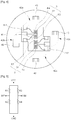
- FIG. 4 is an exaggerated plan view illustrating wire bonding between the strain gauges and the first to fourth electrode terminals
- FIG. 5 is a circuit diagram of a Wheatstone bridge corresponding to FIG. 4 .
- first and third electrode terminals 42a and 42c Corresponding ends of the first and third electrode terminals 42a and 42c, positioned opposite to each other so as to constitute a Wheatstone bridge circuit pattern, are exposed through the first and second exposure grooves 411 and 412, respectively. Also, corresponding ends of the second and fourth electrode terminals 42b and 42d, positioned opposite to each other so as to constitute the Wheatstone bridge circuit pattern, are exposed through the first and second exposure grooves 411 and 412, respectively.
- the fourth pressure resistance element R4 and the third pressure resistance element R3 are connected to the first electrode terminal 42a and the third electrode terminal 42c exposed through the first exposure groove 411, respectively.
- the electrode 32 located between the third pressure resistance element R3 and the fourth pressure resistance element R4 is connected to the second electrode terminal 42b exposed through the first exposure groove 411.
- the second pressure resistance element R2 and the first pressure resistance element R1 are connected to the first electrode terminal 42a and the third electrode terminal 42c exposed through the second exposure groove 412, respectively.
- the electrode 31 located between the first pressure resistance element R1 and the second pressure resistance element R2 is connected to the fourth electrode terminal 42d exposed through the second exposure groove 412.
- the first and third electrode terminals 42a and 42c are disposed in the upper end of the socket unit 4 such that the first and third electrode terminals 42a and 42c are opposite to each other.
- Each of the first and third electrode terminals 42a and 42c is formed in a horseshoe shape.
- Corresponding ends of the first and third electrode terminals 42a and 42c are exposed through the first and second exposure grooves 411 and 412, respectively.
- one end of the second electrode terminal 42b is exposed through the first exposure groove 411.
- the second electrode terminal 42b is formed independently of the other electrode terminals.
- one end of the fourth electrode terminal 42d is exposed through the second exposure groove 412.
- the fourth electrode terminal 42d is also formed independently of the other electrode terminals.
- the pressure resistance elements and the electrodes of the respective strain gauges 3 are connected to the corresponding ends of the respective electrode terminals through the first and second exposure grooves 411 and 412 by wire bonding so as to constitute the Wheatstone bridge.
- Electrode terminals Nodes of Wheatstone bridge Electrode tip of first electrode terminal GND Electrode tip of second electrode terminal INM Electrode tip of third electrode terminal VCC Electrode tip of fourth electrode terminal INP
- the first to fourth electrode terminals 42a, 42b, 42c, and 42d and the strain gauges 3 are connected to each other by wire bonding so as to constitute the Wheatstone bridge circuit pattern.
- the circuit board 5 processes output values received from the respective electrode tips 43 and transmits a pressure value measured by the electrode rods 61 contacting the top of the circuit board 5 to an external device.
- the vertical pressure sensor may further include a shielding shell 7 to surround the top of the circuit board 5 so as to improve shielding performance of the circuit board 5.
- the shielding shell 7 is open at the lower end thereof.
- the shielding shell 7 is provided at the upper end thereof with a passage hole having a diameter sufficient for the respective electrode rods 61 to pass through the passage hole without contact between the electrode rods 61 and the passage hole.
- the bottom 71 of the shielding shell 7 is electrically connected to a ground wire (not shown) of the circuit board 5, and the outer circumference 72 of the shielding shell 7 is electrically connected to the inside of the sensor housing 1, thereby protecting the circuit from external electromagnetic waves.
- the vertical pressure sensor according to the present invention is assembled as follows.
- the upper structure is constituted by coupling the circuit board 5, the shielding shell 7, the electrode rods 61, and the rod housing 6 to one another
- the lower structure is constituted by coupling the pressure application unit 2 and the socket unit 4 to each other.
- the upper structure and the lower structure are sequentially inserted into the sensor housing 1 such that the upper structure and the lower structure are fixed in the sensor housing 1.
- Mechanical coupling and electrical connection between the upper structure and the lower structure are achieved by mechanically coupling and electrically connecting the electrode tips 43 of the first to fourth electrode terminals 42a, 42b, 42c, and 42d protruding from the socket unit 4 to the circuit board 5.
- the present invention uses the first to fourth electrode terminals in place of the first circuit board, which constitutes a Wheatstone bridge, of the conventional pressure sensor, with the result that the first circuit board and the elastic terminals may be removed from the vertical pressure sensor. Consequently, a space defined between the upper end of the socket unit and the circuit board is reduced, and therefore, it is possible to manufacture the vertical pressure sensor in a compact structure.
- the structure of the vertical pressure sensor according to the present invention is simplified as compared with the conventional pressure sensor, and therefore, it is possible to reduce effort and time necessary to assemble the vertical pressure sensor, thereby further improving productivity.
- the shielding shell surrounds the upper end of the circuit board while connecting the ground wire of the circuit board and the sensor housing to each other, and therefore, it is possible to improve shielding performance of the circuit board, thereby further improving operation reliability.
- the vertical pressure sensor includes the first to fourth electrode terminals connected to the circuit board while constituting the Wheatstone bridge circuit pattern. Consequently, the present invention has the effect of reducing the vertical size of the pressure sensor installed at a place having a limited sectional area.
- the structure of the vertical pressure sensor according to the present invention is simplified as compared with the conventional pressure sensor, and therefore, it is possible to easily assemble the vertical pressure sensor. Consequently, the present invention has the effect of improving productivity. Furthermore, the socket unit and the electrode terminals are manufactured in a simple rigid structure. Consequently, the present invention has the effect of improving stability and safety of the vertical pressure sensor.
- the shielding shell is further provided to improve shielding performance with respect to the circuit board. Consequently, the present invention has the effect of reducing a possibility of malfunction due to interference with external electromagnetic waves.
- the present invention has industrial applicability.
Landscapes
- Physics & Mathematics (AREA)
- General Physics & Mathematics (AREA)
- Measuring Fluid Pressure (AREA)
- Pressure Sensors (AREA)
Description
- The present invention relates to a sensor that is capable of measuring pressure transmitted to one end thereof, and, more particularly, to a vertical pressure sensor wherein assembly efficiency of components constituting the vertical pressure sensor is improved under conditions in which the sectional area for installation of the vertical pressure sensor is limited.
- In a pressure measuring structure, a diaphragm is generally provided perpendicularly to the direction in which pressure is applied such that the diaphragm can be finely elastically deformed due to the pressure applied to the diaphragm, and four strain gauges are attached to the top of the diaphragm so as to convert the elastic deformation of the diaphragm into an electrical signal (generally, a voltage displacement difference). At this time, the strain gauges are attached to the diaphragm such that the strain gauges are provided in a pair symmetrical with respect to the center of the diaphragm. A Wheatstone bridge circuit formed on a printed circuit board (PCB) accurately calculates a pressure value applied to the diaphragm from the electric signal obtained by the strain gauges.
- Generally, a pressure sensor may include an input unit, having a diaphragm, to receive external pressure, a first circuit board electrically connected to strain gauges of the diaphragm to receive an electric signal from the strain gauges and processing the received electric signal using a Wheatstone bridge circuit, and a second circuit board electrically connected to the first circuit board, the second circuit board having a circuit device to transmit a pressure value to a controller provided outside the sensor.
- Meanwhile, the size of the pressure sensor may be restricted. For example, a pressure sensor may be mounted to an external signal processing (ESP) module used in an antilock brake system (ABS) for automobiles. As is well known, a solenoid valve, a pump line and the like are densely disposed in the ESP module. The ESP module is filled with a highpressure fluid, which is pulsated to perform braking when the ESP module is driven. The components of the ESP module are disposed as densely as possible so as to reduce the size of the device. In addition, it is necessary to configure a pressure sensor provided to sense pressure of the fluid in the ESP module such that the sectional area of the pressure sensor is limited.
- Such a pressure sensor is schematically shown in
FIG. 7 , which is a sectional view illustrating a conventional pressure sensor. - A
diaphragm 221 is formed at the upper end of aninput unit 220, which is coupled to the lower end of acylindrical casing 210. Fourstrain gauges 222 are attached to the top of thediaphragm 221. Asocket 223, made of a metal material, is coupled to the upper part of theinput unit 220 such that thesocket 223 surrounds theinput unit 220. Afirst circuit board 230 having a Wheatstone bridge circuit mounted therein is securely coupled to the upper end of thesocket 223. - The
strain gauges 222 are electrically connected to thefirst circuit board 230 by wire bonding such that influence on elastic deformation of thediaphragm 221 is minimized. In this case, the distance between the top of thediaphragm 221, to which thestrain gauges 222 are attached, and thefirst circuit board 230 is restricted such that the distance does not exceed a predetermined value, i.e., such that welding portions are not separated from opposite ends ofwires 240, which are inclined, when the relative position between thestrain gauges 222 and thefirst circuit board 230 is changed due to elastic deformation of thediaphragm 221. - Meanwhile, a
second circuit board 270 is coupled to the upper end of thecylindrical casing 210.Electrode rods 250 disposed in thepressure sensor 200, such that theelectrode rods 250 protrude upward from thepressure sensor 200, to transmit a pressure value to the outside are electrically connected to the top of thesecond circuit board 270. Thesecond circuit board 270 is provided withelastic terminals 260 protruding downward to receive the pressure value generated by thefirst circuit board 230. - The
first circuit board 230 is provided at the center thereof with a hole through which thestrain gauges 222 are connected to thefirst circuit board 230 by wire bonding. It may be assumed that a plurality of electrode rods are mounted around the hole of thefirst circuit board 230 in order for thefirst circuit board 230 to be directly electrically connected to contact points (not shown) of an ESP module. In this case, the distance between the respective electrode rods is great due to the hole formed at the center of thefirst circuit board 230, with the result that the electrode rods may not be aligned with the respective contact points formed at the ESP module. For this reason, thesecond circuit board 270 is further provided between thefirst circuit board 230 and the contact points of the ESP module such that the first circuit board and the second circuit board are electrically connected to each other via a plurality of electrode rods disposed at great intervals, and electrical connection between the second circuit board and the ESP module via a plurality of electrode rods densely disposed at the center of the second circuit board. In the conventional pressure sensor, as described above, the hole is formed in the first circuit board, and therefore, the first circuit board and the second circuit board are necessary. - Also, each of the
elastic terminals 260 includes anouter pipe body 261 having a spring (not shown) mounted therein, theouter pipe body 261 fixedly extending through thesecond circuit board 270, and aninner pipe body 262 disposed in theouter pipe body 261 such that theinner pipe body 262 can elastically slide upward. Theouter pipe body 261 and theinner pipe body 262 are made of a conductive material. When theinput unit 220 is inserted into the lower end of thecylindrical casing 210, the elastic terminals elastically move upward to contact an electrical pattern (not shown) formed on thefirst circuit board 230. - The
elastic terminals 260 cannot be fixed to thefirst circuit board 230 because the distance between the top of the diaphragm and the first circuit board is restricted. That is, if theouter pipe body 261 is placed under thefirst circuit board 230 so as to securely couple theelastic terminals 260 to thefirst circuit board 230, the distance between thestrain gauges 222 and thefirst circuit board 230 is excessively increased due to the length of theouter pipe body 261 protruding from the lower end of thefirst circuit board 230, with the result that welded portions of the wires may not be stably maintained during a designed life span. - In the conventional pressure sensor, therefore, the first circuit board having the Wheatstone bridge circuit and the second circuit board having a circuit device are separated from each other in a state in which the second circuit board is disposed above the first circuit board, and the upper and lower circuit boards are connected to each other via the elastic terminals, due to a restricted area of the pressure sensor.
- Since the elastic terminals are used in the conventional pressure sensor, the distance between the first and second circuit boards is increased so as to provide a space necessary for the elastic terminals to expand and contract, with the result that the vertical length of the pressure sensor is increased.
- Also, each of the elastic terminals includes a plurality of components, such as the outer pipe body, the inner pipe body, and the spring, with the result that assembly efficiency is lowered, and manufacturing costs are increased.
- A further pressure sensor is disclosed in patent
US 2005/0230768 A1 . The sensor includes a cap, a lower end of which is closed by a pressure port member including a diaphragm on the top of which strain gauges are mounted which can be piezoresistive sensors and can act as four branches of a Wheatstone bridge. A bracket is attached to the top of the pressure port member to which an interface circuit board is connected. Wires link contact pads on the interface circuit board to the strain gauges and pass through a cutout in the interface circuit board. Traces on the interface circuit board link the contact pads to sockets. Contact pins extend upwardly from the sockets and engage a circuit board forming part of an electronics portion of the sensor situated in an upper region of the sensor. - A still further pressure sensor is disclosed in patent
US 2003/0233881 A1 . The sensor includes a sensor housing in which a pressure detector body is mounted an upper part of which comprises a diaphragm on which a resistance bridge is disposed, An annular metal disc, which surrounds the diaphragm and on which a circuit board is mounted, is connected to the pressure detector body. Contact surfaces on an underside of the circuit board contact complementary contact surfaces of the resistance bridge. Spring contacts interconnect the upper side of the circuit board with connector pins mounted in a connector body attached to the sensor housing, for connection to a complementary connector. - A still further pressure sensor is disclosed in patent
EP 1211496 A2 . The pressure sensor includes an externally screw-threaded joint member with a through passage which communicates with a passage in a pressure detecting device connected to a top of the joint member and includes a diaphragm to an upper surface of which a strain gauge is mounted. A multi-layered circuit board surrounds the pressure detecting device and includes conductive pads some of which are wire-bonded to the strain gauge and others of which are connected by means of input/output terminals to terminals mounted in a housing of the pressure sensor for connection to a complementary plug. - A still further pressure sensor is disclosed in patent
US 7000478 . The sensor includes a tubular probe in one end of which a pressure sensing element with piezo-resistive elements mounted thereon is fixed. The piezo-resistive elements are wire bonded to a first circuit board. An inner connector having an insulating body with axial strain absorbing contacts is also provided. These contacts extend through a gel dam and into contact with the first circuit board and extend up the inner connector and into contacts with a second printed circuit board which includes contact landing pads which are contacted by spring contacts mounted in a cover. - A still further pressure sensor is disclosed in patent
DE 10244760 A1 (on which the preamble ofclaim 1 is based). The pressure sensor includes a measuring element carrier with a diaphragm on which piezo-electric elements are mounted, which are wire bonded to contacts which are embedded in a contact carrier which is secured to the measuring element carrier by resilient retaining elements with hooks which engage a channel which extends around the measuring element carrier. A so-called threading funnel is secured in a similar manner over the contact carrier and acts to guide rod-shaped contacts into engagement with the contacts of the contact carrier. - Therefore, the present invention has been made in view of the above problems, and it is an object of the present invention to provide a vertical pressure sensor wherein the sectional area for installation of the vertical pressure sensor is minimized, and assembly efficiency of components of the vertical pressure sensor is improved.
- It is another object of the present invention to provide a vertical pressure sensor wherein an electrical signal measured by strain gauges is transmitted to an electric circuit using a simple structure, whereby stability and safety of the vertical pressure sensor are improved, and assembly of the vertical pressure sensor is easily achieved.
- It is a further object of the present invention to provide a vertical pressure sensor having improved shielding performance.
- According to the invention there is provided a pressure sensor as claimed in
claim 1. - Also, the through hole may be provided at an inner circumference thereof with first and second exposure grooves. In addition, one end of each of the first and third electrode terminals disposed opposite to each other may be exposed through a corresponding one of the first and second exposure grooves, and one end of each of the second and fourth electrode terminals may be exposed through a corresponding one of the first and second exposure grooves.
- Also, the strain gauges may be attached to the diaphragm on an imaginary line passing through a center of the diaphragm, and the strain gauges may include a first pressure resistance element, a second pressure resistance element, a third pressure resistance element, and a fourth pressure resistance element attached to the diaphragm such that the first and second pressure resistance elements and the third and fourth pressure resistance elements are positioned symmetrically with respect to the center of the diaphragm and such that the first pressure resistance element and the second pressure resistance element correspond to each other, and the third pressure resistance element and the fourth pressure resistance element correspond to each other. Furthermore, the fourth pressure resistance element and the third pressure resistance element may be connected to the first electrode terminal and the third electrode terminal exposed through the first exposure groove, respectively, and an electrode located between the third pressure resistance element and the fourth pressure resistance element may be connected to the second electrode terminal exposed through the first exposure groove. In addition, the second pressure resistance element and the first pressure resistance element may be connected to the first electrode terminal and the third electrode terminal exposed through the second exposure groove, respectively, and an electrode located between the first pressure resistance element and the second pressure resistance element may be connected to the fourth electrode terminal exposed through the second exposure groove.
- Also, the vertical pressure sensor may further include a shielding shell coupled to the circuit board so as to surround a top of the circuit board. The shielding shell may be electrically connected to a ground wire of the circuit board at the bottom thereof. In addition, the shielding shell may be electrically connected to the inside of the sensor housing at an outer circumference thereof.
- As is apparent from the above description, the vertical pressure sensor according to the embodiment of the present invention includes the first to fourth electrode terminals connected to the circuit board while constituting the Wheatstone bridge circuit pattern. Consequently, the present invention has the effect of reducing the vertical size of the pressure sensor installed at a place having a limited sectional area.
- Also, the structure of the vertical pressure sensor according to the present invention is simplified as compared with the conventional pressure sensor, and therefore, it is possible to easily assemble the vertical pressure sensor. Consequently, the present invention has the effect of improving productivity. Furthermore, the socket unit and the electrode terminals are manufactured in a simple rigid structure. Consequently, the present invention has the effect of improving stability and safety of the vertical pressure sensor.
- In addition, the shielding shell is further provided to improve shielding performance with respect to the circuit board. Consequently, the present invention has the effect of reducing a possibility of malfunction due to interference with external electromagnetic waves.
- The above and other objects, features and other advantages of the present invention will be more clearly understood from the following detailed description taken in conjunction with the accompanying drawings, in which:
-
FIG. 1 is a perspective view illustrating a vertical pressure sensor according to an embodiment of the present invention; -
FIG. 2 is an exploded perspective view of the vertical pressure sensor shown inFIG. 1 ; -
FIG. 3 is a view illustrating a socket unit and first to fourth electrode terminals of the vertical pressure sensor; -
FIG. 4 is an exaggerated plan view illustrating wire bonding between strain gauges and the first to fourth electrode terminals -
FIG. 5 is a circuit diagram of a Wheatstone bridge corresponding toFIG. 4 ; -
FIG. 6 is a sectional view of the vertical pressure sensor shown inFIG. 1 ; and -
FIG. 7 is a sectional view illustrating a conventional pressure sensor. - Now, a preferred embodiment of the present invention will be described in detail with reference to the accompanying drawings. In the following, a detailed description of known functions and configurations incorporated herein will be omitted when it may make the subject matter of the present invention rather unclear.
-
FIG. 1 is a perspective view illustrating a vertical pressure sensor according to an embodiment of the present invention, andFIG. 2 is an exploded perspective view of the vertical pressure sensor shown inFIG. 1 . - In this embodiment, a
vertical pressure sensor 100 is formed in a vertically long shape with a circular cross section. The size of the circular section of thevertical pressure sensor 100 is limited by a mechanical apparatus to which thevertical pressure sensor 100 is mounted. Thevertical pressure sensor 100 is provided at the lower end thereof with apressure application unit 2 to which pressure is applied. Thevertical pressure sensor 100 is provided at the upper end thereof with anelectrode rod 61 protruding upward to transmit an electrical signal corresponding to the pressure applied to thepressure application unit 2 to the outside. Thevertical pressure sensor 100 is hermetically sealed to prevent an external fluid from permeating into asensor housing 1 of thevertical pressure sensor 100. - As shown in
FIG. 2 ofFIG. 3 , thevertical pressure sensor 100 according to the present invention includes apressure application unit 2 having adiaphragm 21 to whichstrain gauges 3, asocket unit 4 formed by insert injection molding such that first tofourth electrode terminals socket unit 4, acircuit board 5 connected to the respective electrode terminals to process an electrical signal, andelectrode rods 61 connected to thecircuit board 5 to transmit the electrical signal to the outside. - The
sensor housing 1 constituting the circumference of thevertical pressure sensor 100 is formed of a cylindrical pipe. Thesensor housing 1 is made of a conductive material, such as metal, for shielding. Also, the upper end of thesensor housing 1 is bent inward. - The
electrode rods 61 mounted to arod housing 6, which serves as an insulator, and thecircuit board 5 coupled to the lower end of therod housing 6 constitute the upper structure of thevertical pressure sensor 100. The lower ends of theelectrode rods 61 are connected to an output electrode surface (not shown) formed at the top of thecircuit board 5. Meanwhile, a shieldingshell 7 may be coupled to the lower end of therod housing 6, and thecircuit board 5 may be coupled to the lower end of the shieldingshell 7, which will be described later. - The upper structure of the
vertical pressure sensor 100 assembled as described above is inserted into thesensor housing 1 from the lower end thereof in a state in which a sealing member S is disposed between the upper structure of thevertical pressure sensor 100 and thesensor housing 1. The upper ends of theelectrode rods 61 protrude from the top of thevertical pressure sensor 100 such that the upper ends of theelectrode rods 61 can be coupled to a connector (not shown) of another mechanical apparatus. - Meanwhile, the
pressure application unit 2 has a step formed at the outer circumference thereof. Thepressure application unit 2 is coupled to the lower end of thesensor housing 1. Thediaphragm 21 is formed at the upper end of thepressure application unit 2. Thediaphragm 21 is formed of a flat disc. Thepressure application unit 2 is provided at the lower end thereof with anintroduction hole 22 through which an object, such as a fluid, pressure of which is to be measured, moves to the back of thediaphragm 21. The fluid reaches the back of thediaphragm 21 through theintroduction hole 22, and thediaphragm 21 is finely elastically deformed due to the increase in pressure of the fluid. - Meanwhile, as shown in
FIG. 3 , thestrain gauges 3 are attached to the upper end of thediaphragm 21 on an imaginary line L passing through thecenter 21a of thediaphragm 21. A first pressure resistance element R1, a second pressure resistance element R2, a third pressure resistance element R3, and a fourth pressure resistance element R4 are attached to the upper end of thediaphragm 21 such that the first and second pressure resistance elements R1 and R2 and the third and fourth pressure resistance elements R3 and R4 are positioned symmetrically with respect to thecenter 21a of thediaphragm 21 and such that the first pressure resistance element R1 and the second pressure resistance element R2 correspond to each other, and the third pressure resistance element R3 and the fourth pressure resistance element R4 correspond to each other. - Preferably, semiconductor type strain gauges exhibiting a high gauge rate are used as the strain gauges 3. A pair of neighboring pressure resistance elements is provided at each of the
strain gauges 3 so as to constitute a single member, andelectrodes - The strain gauges 3 are attached to the upper end of the
diaphragm 21 such that thestrain gauges 3 are positioned symmetrically with respect to the center of thediaphragm 21, and therefore, thestrain gauges 3 have symmetric output values when thediaphragm 21 is deformed. In this specification, the first to fourth pressure resistance elements are sequentially arranged in one direction for the convenience of description. - Structurally, the first pressure resistance element R1 and the fourth pressure resistance element R4 are attached to the upper end of the
diaphragm 21 equidistant from the center of thediaphragm 21 such that the first pressure resistance element R1 and the fourth pressure resistance element R4 are positioned symmetrically with respect to the center of thediaphragm 21. In the same manner, the second pressure resistance element R2 and the third pressure resistance element R3 are attached to the upper end of thediaphragm 21 equidistant from the center of thediaphragm 21, which are shorter than in the first pressure resistance element R1 and the fourth pressure resistance element R4, such that the second pressure resistance element R2 and the third pressure resistance element R3 are positioned symmetrically with respect to the center of thediaphragm 21. - Meanwhile, the
socket unit 4 is an insulator to surround the circumference of thediaphragm 21 of thepressure application unit 2 while being spaced apart from thediaphragm 21 by a predetermined distance. Thesocket unit 4 has a throughhole 41 corresponding to the upper end of thediaphragm 21. - That is, as shown in
FIG. 6 , thesocket unit 4 is formed in a shape to surround the upper part of thepressure application unit 2. Also, thesocket unit 4 is spaced apart from the circumference of thediaphragm 21 such that the inside of thesocket unit 4 does not interfere with deformation of thediaphragm 21, which is elastically deformed by external pressure. - The first to
fourth electrode terminals socket unit 4. Thesocket unit 4 may be manufactured by insert injection molding. - Meanwhile, the first to
fourth electrode terminals corresponding strain gauges 3 by wire bonding to transmit output values obtained from the strain gauges to thecircuit board 5. The first tofourth electrode terminals - Specifically, as shown in
FIG. 3 , the Wheatstone bridge circuit pattern of the first tofourth electrode terminals socket unit 4. One end of each pattern is exposed through the throughhole 41 and is connected to a corresponding one of thestrain gauges 3 by the wire bonding. - An
electrode tip 43 extending upward from each electrode terminal pattern protrudes from thesocket unit 4 and is connected to thecircuit board 5 to transmit an output value to thecircuit board 5. As shown inFIG. 2 , the upper end of eachelectrode tip 43 may be fixedly inserted into acorresponding connection hole 51. - The through
hole 41 of thesocket unit 4 provides a space in which a working tool of an automated wire bonding machine (not shown) performs a welding operation during wire bonding between thestrain gauges 3 and the first tofourth electrode terminals hole 41. - In order to sufficiently secure the working space of the working tool, first and
second exposure grooves second exposure grooves exposure grooves - Therefore, the through hole, which is the working space of the working tool, may be formed in a polygonal shape or in a circular shape, with the result that it is possible to easily operate the wire boding machine.
- Meanwhile,
FIG. 4 is an exaggerated plan view illustrating wire bonding between the strain gauges and the first to fourth electrode terminals, andFIG. 5 is a circuit diagram of a Wheatstone bridge corresponding toFIG. 4 . - Corresponding ends of the first and
third electrode terminals second exposure grooves fourth electrode terminals second exposure grooves - Also, the fourth pressure resistance element R4 and the third pressure resistance element R3 are connected to the
first electrode terminal 42a and thethird electrode terminal 42c exposed through thefirst exposure groove 411, respectively. Theelectrode 32 located between the third pressure resistance element R3 and the fourth pressure resistance element R4 is connected to thesecond electrode terminal 42b exposed through thefirst exposure groove 411. - In the same manner, the second pressure resistance element R2 and the first pressure resistance element R1 are connected to the
first electrode terminal 42a and thethird electrode terminal 42c exposed through thesecond exposure groove 412, respectively. Theelectrode 31 located between the first pressure resistance element R1 and the second pressure resistance element R2 is connected to thefourth electrode terminal 42d exposed through thesecond exposure groove 412. - The first and
third electrode terminals socket unit 4 such that the first andthird electrode terminals third electrode terminals third electrode terminals second exposure grooves second electrode terminal 42b is exposed through thefirst exposure groove 411. Thesecond electrode terminal 42b is formed independently of the other electrode terminals. In addition, one end of thefourth electrode terminal 42d is exposed through thesecond exposure groove 412. Thefourth electrode terminal 42d is also formed independently of the other electrode terminals. - The pressure resistance elements and the electrodes of the
respective strain gauges 3 are connected to the corresponding ends of the respective electrode terminals through the first andsecond exposure grooves - A relationship between the
electrode tips 43 of the respective first tofourth electrode terminals -
[Table ] Electrode terminals Nodes of Wheatstone bridge Electrode tip of first electrode terminal GND Electrode tip of second electrode terminal INM Electrode tip of third electrode terminal VCC Electrode tip of fourth electrode terminal INP - As described above, the first to
fourth electrode terminals strain gauges 3 are connected to each other by wire bonding so as to constitute the Wheatstone bridge circuit pattern. - Meanwhile, the
circuit board 5 processes output values received from therespective electrode tips 43 and transmits a pressure value measured by theelectrode rods 61 contacting the top of thecircuit board 5 to an external device. - Referring to
FIGS. 2 and6 again, the vertical pressure sensor may further include a shieldingshell 7 to surround the top of thecircuit board 5 so as to improve shielding performance of thecircuit board 5. - The shielding
shell 7 is open at the lower end thereof. The shieldingshell 7 is provided at the upper end thereof with a passage hole having a diameter sufficient for therespective electrode rods 61 to pass through the passage hole without contact between theelectrode rods 61 and the passage hole. Also, the bottom 71 of the shieldingshell 7 is electrically connected to a ground wire (not shown) of thecircuit board 5, and theouter circumference 72 of the shieldingshell 7 is electrically connected to the inside of thesensor housing 1, thereby protecting the circuit from external electromagnetic waves. - Hereinafter, the operation of the vertical pressure sensor according to the embodiment of the prevent invention will be described with reference to the accompanying drawings.
- The vertical pressure sensor according to the present invention is assembled as follows. The upper structure is constituted by coupling the
circuit board 5, the shieldingshell 7, theelectrode rods 61, and therod housing 6 to one another, and the lower structure is constituted by coupling thepressure application unit 2 and thesocket unit 4 to each other. The upper structure and the lower structure are sequentially inserted into thesensor housing 1 such that the upper structure and the lower structure are fixed in thesensor housing 1. - Mechanical coupling and electrical connection between the upper structure and the lower structure are achieved by mechanically coupling and electrically connecting the
electrode tips 43 of the first tofourth electrode terminals socket unit 4 to thecircuit board 5. - As compared with the conventional pressure sensor, the present invention uses the first to fourth electrode terminals in place of the first circuit board, which constitutes a Wheatstone bridge, of the conventional pressure sensor, with the result that the first circuit board and the elastic terminals may be removed from the vertical pressure sensor. Consequently, a space defined between the upper end of the socket unit and the circuit board is reduced, and therefore, it is possible to manufacture the vertical pressure sensor in a compact structure.
- Also, the structure of the vertical pressure sensor according to the present invention is simplified as compared with the conventional pressure sensor, and therefore, it is possible to reduce effort and time necessary to assemble the vertical pressure sensor, thereby further improving productivity.
- In addition, the shielding shell surrounds the upper end of the circuit board while connecting the ground wire of the circuit board and the sensor housing to each other, and therefore, it is possible to improve shielding performance of the circuit board, thereby further improving operation reliability.
- Various embodiments have been described in the best mode for carrying out the invention.
- According to the present invention, the vertical pressure sensor includes the first to fourth electrode terminals connected to the circuit board while constituting the Wheatstone bridge circuit pattern. Consequently, the present invention has the effect of reducing the vertical size of the pressure sensor installed at a place having a limited sectional area.
- Also, the structure of the vertical pressure sensor according to the present invention is simplified as compared with the conventional pressure sensor, and therefore, it is possible to easily assemble the vertical pressure sensor. Consequently, the present invention has the effect of improving productivity. Furthermore, the socket unit and the electrode terminals are manufactured in a simple rigid structure. Consequently, the present invention has the effect of improving stability and safety of the vertical pressure sensor.
- In addition, the shielding shell is further provided to improve shielding performance with respect to the circuit board. Consequently, the present invention has the effect of reducing a possibility of malfunction due to interference with external electromagnetic waves.
- Therefore, the present invention has industrial applicability.
- Although the preferred embodiment of the present invention has been disclosed for illustrative purposes, those skilled in the art will appreciate that various modifications, additions and substitutions are possible, without departing from the scope of the invention as disclosed in the accompanying claims.
Claims (4)
- A vertical pressure sensor (100) comprising:a pressure application unit (2) configured to be deformed by a fluid, which is an object to be measured, the pressure application unit (2) being provided at an upper end thereof with a diaphragm (21) to which strain gauges (3) are attached at a top thereof, the fluid contacting the back of the diaphragm (21) with the pressure application unit (2) being coupled to a lower part of a sensor housing (1);a socket unit (4) surrounding a circumference of the diaphragm (21) of the pressure application unit (2), the socket unit (4) having a through hole (41) corresponding to an upper end of the diaphragm (21); andfirst to fourth electrode terminals (42a - 42d) provided in an upper end of the socket unit (4), one end of each of the first to fourth electrode terminals (42a - 42d) exposed through the through hole (41) and being electrically connected to a corresponding one of the strain gauges (3) by wire bonding, the other end of each of the first to fourth electrode terminals (42a - 42d) exposed at the upper end of the socket unit (4) characterised in that:(i) the socket unit (4) is spaced apart from the diaphragm (21) by a predetermined distance;(ii) each of the first to fourth electrode terminals protrudes from the upper end of the socket unit (4) to constitute an electrode tip (43), the electrode tip (43) of each of the first to fourth electrode terminals (42a-42d) being connected to a circuit board (5) of the pressure sensor (100) and is fixedly inserted into a corresponding connection hole (51) of the circuit board (5) and wherein a Wheatstone bridge circuit pattern of the first to fourth electrode terminals (42a-42d) is constituted by patterns of the respective electrode terminals (42a-42d) disposed in the upper end of the socket unit (4);(iii) the circuit board (5) is connected to the first to fourth electrode terminals (42a - 42d) to convert a measured pressure value into an electrical signal; and(iv) the pressure sensor (100) further comprises electrode rods (61) connected to a top of the circuit board (5) to transmit the electrical signal outside.
- The vertical pressure sensor (100) according to claim 1, wherein:the through hole (41) of the socket unit (4) is provided at an inner circumference thereof with first and second exposure grooves (411, 412); andone end of each of the first and third electrode terminals (42a, 42c) disposed opposite to each other is exposed through a corresponding one of the first and second exposure grooves (411, 412), and one end of each of the second and fourth electrode terminals (42b, 42d) is exposed through a corresponding one of the first and second exposure grooves (411, 412).
- The vertical pressure sensor (100) according to claim 2, wherein:the strain gauges (3) are attached to the diaphragm (21) on an imaginary line (4) passing through a center (21a) of the diaphragm (21), the strain gauges (3) comprising a first resistance element (R1), a second resistance element (R2), a third resistance element (R3), and a fourth resistance element (R4) attached to the diaphragm (21) such that the first and second resistance elements (R1, R2) and the third and fourth resistance elements (R3, R4) are positioned symmetrically with respect to the center (21a) of the diaphragm (21) and such that the first resistance element (R1) and the second resistance element (R2) correspond to each other, and the third resistance element (R3) and the fourth resistance element (R4) correspond to each other;the fourth resistance element (R4) and the third resistance (R3) element are connected to the first electrode terminal (42a) and the third electrode terminal (42c) exposed through the first exposure groove (411), respectively, and an electrode located between the third resistance element (R3) and the fourth resistance element (R4) is connected to the second electrode terminal (42b) exposed through the first exposure groove (411); andthe second resistance element (R2) and the first resistance element (R1) are connected to the first electrode terminal (42a) and the third electrode terminal (42c) exposed through the second exposure groove (412), respectively, and an electrode located between the first resistance element (R1) and the second resistance element (R2) is connected to the fourth electrode terminal (42d) exposed through the second exposure groove (412).
- The vertical pressure sensor (100) according to any one of claims 1 to 3, further comprising a shielding shell (7) coupled to the circuit board (5) so as to surround a top of the circuit board (5), wherein the shielding shell (7) is electrically connected to a ground wire of the circuit board (5) at a bottom thereof, the shielding shell (7) is electrically connected to an inside of the sensor housing (1) at an outer circumference thereof.
Applications Claiming Priority (2)
| Application Number | Priority Date | Filing Date | Title |
|---|---|---|---|
| KR1020090097862A KR101600089B1 (en) | 2009-10-14 | 2009-10-14 | Vertical Pressure Sensor |
| PCT/KR2010/006248 WO2011046302A2 (en) | 2009-10-14 | 2010-09-14 | Vertical pressure sensor |
Publications (3)
| Publication Number | Publication Date |
|---|---|
| EP2488843A2 EP2488843A2 (en) | 2012-08-22 |
| EP2488843A4 EP2488843A4 (en) | 2017-12-20 |
| EP2488843B1 true EP2488843B1 (en) | 2021-10-27 |
Family
ID=43876660
Family Applications (1)
| Application Number | Title | Priority Date | Filing Date |
|---|---|---|---|
| EP10823544.1A Active EP2488843B1 (en) | 2009-10-14 | 2010-09-14 | Vertical pressure sensor |
Country Status (5)
| Country | Link |
|---|---|
| US (1) | US8596133B2 (en) |
| EP (1) | EP2488843B1 (en) |
| KR (1) | KR101600089B1 (en) |
| CN (1) | CN102713548B (en) |
| WO (1) | WO2011046302A2 (en) |
Families Citing this family (16)
| Publication number | Priority date | Publication date | Assignee | Title |
|---|---|---|---|---|
| US20130192379A1 (en) * | 2012-01-27 | 2013-08-01 | Neil S. Petrarca | Small form factor microfused silicon strain gage (msg) pressure sensor packaging |
| KR102000294B1 (en) * | 2012-09-28 | 2019-07-15 | 타이코에이엠피 주식회사 | Pressure sensor |
| CN105452830B (en) * | 2013-03-15 | 2018-02-16 | 测量有限公司 | Low section pressure sensor |
| CN105181216B (en) * | 2014-05-29 | 2020-10-16 | 森萨塔科技公司 | Strain gauge type pressure sensor |
| WO2016028047A1 (en) * | 2014-08-19 | 2016-02-25 | 타이코에이엠피 주식회사 | Pressure sensor |
| KR101709671B1 (en) | 2015-06-15 | 2017-02-24 | 금오기전 주식회사 | Pressure sensor using eddy current |
| WO2018119841A1 (en) * | 2016-12-29 | 2018-07-05 | 李志华 | Disinfection device |
| US11153985B2 (en) * | 2017-06-29 | 2021-10-19 | Rosemount Inc. | Modular hybrid circuit packaging |
| EP3839305A4 (en) * | 2018-11-28 | 2022-10-19 | Zhejiang Sanhua Intelligent Controls Co., Ltd. | ELECTRIC VALVE, HEAT MANAGEMENT PACKAGE AND AIR CONDITIONING SYSTEM |
| CN109990924B (en) * | 2019-04-11 | 2021-04-09 | 深圳市迈姆斯科技有限公司 | A pressure signal sensing device and processing method |
| JP7342771B2 (en) * | 2019-04-26 | 2023-09-12 | 株式会社デンソー | pressure sensor |
| CN113644476A (en) * | 2020-05-11 | 2021-11-12 | 精量电子(深圳)有限公司 | Connector and pressure sensor assembly |
| CN111912331A (en) * | 2020-06-28 | 2020-11-10 | 中国电力科学研究院有限公司 | A high-precision strain sensor for grid environment |
| WO2022080069A1 (en) * | 2020-10-15 | 2022-04-21 | 株式会社フジキン | Cover component for pressure sensor, and pressure sensor device comprising same |
| DE102021109841A1 (en) * | 2021-04-19 | 2022-10-20 | Danfoss A/S | Pressure sensor arrangement and manufacturing method for the pressure sensor arrangement |
| US12200888B2 (en) | 2022-02-01 | 2025-01-14 | Rosemount Inc. | Customization of process variable transmitter with hermetically sealed electronics |
Citations (2)
| Publication number | Priority date | Publication date | Assignee | Title |
|---|---|---|---|---|
| US20050230768A1 (en) * | 2004-04-19 | 2005-10-20 | Hai Mei | Pressure sensor device and method |
| US7000478B1 (en) * | 2005-01-31 | 2006-02-21 | Texas Instruments Incorporated | Combined pressure and temperature transducer |
Family Cites Families (20)
| Publication number | Priority date | Publication date | Assignee | Title |
|---|---|---|---|---|
| JPH0777266B2 (en) * | 1988-12-28 | 1995-08-16 | 株式会社豊田中央研究所 | Semiconductor strain detector |
| JPH0821775A (en) * | 1994-07-08 | 1996-01-23 | Fuji Koki Seisakusho:Kk | Pressure sensor |
| JP3488758B2 (en) * | 1995-01-31 | 2004-01-19 | 株式会社共和電業 | Pressure transmitter and method of assembling pressure transmitter |
| KR19990008150A (en) | 1996-03-07 | 1999-01-25 | 노무라마사나리 | Pressure sensor module |
| US5880372A (en) * | 1997-01-10 | 1999-03-09 | Integrated Sensor Solutions | Media compatible pressure sensor device utilizing self-aligned components which fit together without the need for adhesives |
| EP0905496A3 (en) * | 1997-09-30 | 1999-10-13 | Matsushita Electric Works, Ltd. | Pressure sensor |
| DK0915326T3 (en) * | 1997-10-10 | 2002-03-25 | Wika Alexander Wiegand Gmbh | Process for producing a pressure target transducer and pressure target transducer |
| KR19990046020A (en) * | 1999-03-11 | 1999-06-25 | 황덕장 | Resin powder manufacturing method and device |
| JP2001116643A (en) * | 1999-10-20 | 2001-04-27 | Saginomiya Seisakusho Inc | Pressure detecting element for liquid ring type pressure sensor and liquid ring type pressure sensor |
| US6227055B1 (en) * | 1999-11-01 | 2001-05-08 | Delphi Technologies, Inc. | Pressure sensor assembly with direct backside sensing |
| JP3954262B2 (en) * | 2000-02-17 | 2007-08-08 | カヤバ工業株式会社 | Pressure sensor |
| DE10014992C2 (en) * | 2000-03-25 | 2002-01-31 | Bosch Gmbh Robert | sensor arrangement |
| US6584851B2 (en) * | 2000-11-30 | 2003-07-01 | Nagano Keiki Co., Ltd. | Fluid pressure sensor having a pressure port |
| DE10244760A1 (en) * | 2002-02-26 | 2003-10-09 | Continental Teves Ag & Co Ohg | Pressure sensor structural component for a motor vehicle brake unit has electric connection for measuring element, contact carrier and threading funnel for inserting a contact pin |
| JP4101033B2 (en) * | 2002-11-14 | 2008-06-11 | 株式会社鷺宮製作所 | Pressure sensor and terminal connection method in pressure sensor |
| JP4774678B2 (en) | 2003-08-29 | 2011-09-14 | 富士電機株式会社 | Pressure sensor device |
| JP4839648B2 (en) * | 2005-03-23 | 2011-12-21 | 富士電機株式会社 | Pressure sensor device |
| US7252009B2 (en) * | 2004-08-27 | 2007-08-07 | Ashcroft-Nagano, Inc. | System and method for pressure measurement |
| US7100455B2 (en) * | 2004-08-27 | 2006-09-05 | Dresser-Nagano, Inc. | System and method for pressure measurement |
| CN101493371A (en) * | 2008-01-21 | 2009-07-29 | 昆山双桥传感器测控技术有限公司 | Antiradiation pressure sensor |
-
2009
- 2009-10-14 KR KR1020090097862A patent/KR101600089B1/en active Active
-
2010
- 2010-09-14 CN CN201080046976.2A patent/CN102713548B/en active Active
- 2010-09-14 WO PCT/KR2010/006248 patent/WO2011046302A2/en not_active Ceased
- 2010-09-14 EP EP10823544.1A patent/EP2488843B1/en active Active
-
2012
- 2012-04-13 US US13/446,473 patent/US8596133B2/en active Active
Patent Citations (2)
| Publication number | Priority date | Publication date | Assignee | Title |
|---|---|---|---|---|
| US20050230768A1 (en) * | 2004-04-19 | 2005-10-20 | Hai Mei | Pressure sensor device and method |
| US7000478B1 (en) * | 2005-01-31 | 2006-02-21 | Texas Instruments Incorporated | Combined pressure and temperature transducer |
Also Published As
| Publication number | Publication date |
|---|---|
| WO2011046302A2 (en) | 2011-04-21 |
| US8596133B2 (en) | 2013-12-03 |
| CN102713548A (en) | 2012-10-03 |
| WO2011046302A3 (en) | 2011-08-25 |
| EP2488843A2 (en) | 2012-08-22 |
| CN102713548B (en) | 2014-09-03 |
| KR20110040546A (en) | 2011-04-20 |
| US20120297886A1 (en) | 2012-11-29 |
| KR101600089B1 (en) | 2016-03-07 |
| EP2488843A4 (en) | 2017-12-20 |
Similar Documents
| Publication | Publication Date | Title |
|---|---|---|
| US8596133B2 (en) | Vertical pressure sensor | |
| KR100590275B1 (en) | Pressure sensor | |
| JP6009950B2 (en) | Small Form Factor Microfused Silicon Strain Gauge (MSG) Pressure Sensor Packaging | |
| EP3002572B1 (en) | Physical quantity measuring device | |
| EP3538857B1 (en) | Differential pressure sensor and fabrication | |
| KR20110088173A (en) | Vertical pressure sensor | |
| KR20160104551A (en) | Microfused silicon strain gauge (msg) pressure sensor package | |
| CN115752873A (en) | Pressure sensor | |
| US20140331776A1 (en) | Strain Gauge Pressure Sensor | |
| KR20160133227A (en) | Pressure sensor for vehicle | |
| JP2005257497A (en) | Sensor device and connection structure of sensor device | |
| KR20150052599A (en) | Pressure sensor | |
| KR100834337B1 (en) | Pressure sensor device and manufacturing method thereof | |
| CN105181216B (en) | Strain gauge type pressure sensor | |
| KR101606151B1 (en) | A sensor assembly | |
| KR102242428B1 (en) | Strain gauge pressure sensor | |
| WO2012144454A1 (en) | Connector and detecting device using same | |
| CN111936835A (en) | Pressure sensor | |
| US10514312B2 (en) | Hydraulic pressure sensor for a vehicle | |
| US20200064218A1 (en) | Pressure detecting device | |
| KR102382142B1 (en) | Pressure Sensor Package Using One Mold Package | |
| JP6498021B2 (en) | Pressure sensor | |
| JP2012181127A (en) | Pressure sensor | |
| KR101628267B1 (en) | Pressure sensor | |
| CN120063572B (en) | A pressure sensor |
Legal Events
| Date | Code | Title | Description |
|---|---|---|---|
| PUAI | Public reference made under article 153(3) epc to a published international application that has entered the european phase |
Free format text: ORIGINAL CODE: 0009012 |
|
| 17P | Request for examination filed |
Effective date: 20120229 |
|
| AK | Designated contracting states |
Kind code of ref document: A2 Designated state(s): AL AT BE BG CH CY CZ DE DK EE ES FI FR GB GR HR HU IE IS IT LI LT LU LV MC MK MT NL NO PL PT RO SE SI SK SM TR |
|
| DAX | Request for extension of the european patent (deleted) | ||
| RAP1 | Party data changed (applicant data changed or rights of an application transferred) |
Owner name: TYCO ELECTRONICS AMP KOREA CO., LTD. |
|
| A4 | Supplementary search report drawn up and despatched |
Effective date: 20171122 |
|
| RIC1 | Information provided on ipc code assigned before grant |
Ipc: G01L 7/08 20060101ALI20171116BHEP Ipc: G01L 9/04 20060101AFI20171116BHEP Ipc: G01L 19/00 20060101ALI20171116BHEP Ipc: G01L 9/00 20060101ALI20171116BHEP Ipc: G01L 19/14 20060101ALI20171116BHEP |
|
| STAA | Information on the status of an ep patent application or granted ep patent |
Free format text: STATUS: EXAMINATION IS IN PROGRESS |
|
| 17Q | First examination report despatched |
Effective date: 20190916 |
|
| GRAP | Despatch of communication of intention to grant a patent |
Free format text: ORIGINAL CODE: EPIDOSNIGR1 |
|
| STAA | Information on the status of an ep patent application or granted ep patent |
Free format text: STATUS: GRANT OF PATENT IS INTENDED |
|
| INTG | Intention to grant announced |
Effective date: 20210610 |
|
| GRAS | Grant fee paid |
Free format text: ORIGINAL CODE: EPIDOSNIGR3 |
|
| GRAA | (expected) grant |
Free format text: ORIGINAL CODE: 0009210 |
|
| STAA | Information on the status of an ep patent application or granted ep patent |
Free format text: STATUS: THE PATENT HAS BEEN GRANTED |
|
| AK | Designated contracting states |
Kind code of ref document: B1 Designated state(s): AL AT BE BG CH CY CZ DE DK EE ES FI FR GB GR HR HU IE IS IT LI LT LU LV MC MK MT NL NO PL PT RO SE SI SK SM TR |
|
| REG | Reference to a national code |
Ref country code: GB Ref legal event code: FG4D |
|
| REG | Reference to a national code |
Ref country code: CH Ref legal event code: EP |
|
| REG | Reference to a national code |
Ref country code: AT Ref legal event code: REF Ref document number: 1442205 Country of ref document: AT Kind code of ref document: T Effective date: 20211115 |
|
| REG | Reference to a national code |
Ref country code: DE Ref legal event code: R096 Ref document number: 602010067742 Country of ref document: DE |
|
| REG | Reference to a national code |
Ref country code: IE Ref legal event code: FG4D |
|
| REG | Reference to a national code |
Ref country code: LT Ref legal event code: MG9D |
|
| REG | Reference to a national code |
Ref country code: NL Ref legal event code: MP Effective date: 20211027 |
|
| REG | Reference to a national code |
Ref country code: AT Ref legal event code: MK05 Ref document number: 1442205 Country of ref document: AT Kind code of ref document: T Effective date: 20211027 |
|
| PG25 | Lapsed in a contracting state [announced via postgrant information from national office to epo] |
Ref country code: LT Free format text: LAPSE BECAUSE OF FAILURE TO SUBMIT A TRANSLATION OF THE DESCRIPTION OR TO PAY THE FEE WITHIN THE PRESCRIBED TIME-LIMIT Effective date: 20211027 Ref country code: FI Free format text: LAPSE BECAUSE OF FAILURE TO SUBMIT A TRANSLATION OF THE DESCRIPTION OR TO PAY THE FEE WITHIN THE PRESCRIBED TIME-LIMIT Effective date: 20211027 Ref country code: BG Free format text: LAPSE BECAUSE OF FAILURE TO SUBMIT A TRANSLATION OF THE DESCRIPTION OR TO PAY THE FEE WITHIN THE PRESCRIBED TIME-LIMIT Effective date: 20220127 Ref country code: AT Free format text: LAPSE BECAUSE OF FAILURE TO SUBMIT A TRANSLATION OF THE DESCRIPTION OR TO PAY THE FEE WITHIN THE PRESCRIBED TIME-LIMIT Effective date: 20211027 |
|
| PG25 | Lapsed in a contracting state [announced via postgrant information from national office to epo] |
Ref country code: IS Free format text: LAPSE BECAUSE OF FAILURE TO SUBMIT A TRANSLATION OF THE DESCRIPTION OR TO PAY THE FEE WITHIN THE PRESCRIBED TIME-LIMIT Effective date: 20220227 Ref country code: SE Free format text: LAPSE BECAUSE OF FAILURE TO SUBMIT A TRANSLATION OF THE DESCRIPTION OR TO PAY THE FEE WITHIN THE PRESCRIBED TIME-LIMIT Effective date: 20211027 Ref country code: PT Free format text: LAPSE BECAUSE OF FAILURE TO SUBMIT A TRANSLATION OF THE DESCRIPTION OR TO PAY THE FEE WITHIN THE PRESCRIBED TIME-LIMIT Effective date: 20220228 Ref country code: PL Free format text: LAPSE BECAUSE OF FAILURE TO SUBMIT A TRANSLATION OF THE DESCRIPTION OR TO PAY THE FEE WITHIN THE PRESCRIBED TIME-LIMIT Effective date: 20211027 Ref country code: NO Free format text: LAPSE BECAUSE OF FAILURE TO SUBMIT A TRANSLATION OF THE DESCRIPTION OR TO PAY THE FEE WITHIN THE PRESCRIBED TIME-LIMIT Effective date: 20220127 Ref country code: NL Free format text: LAPSE BECAUSE OF FAILURE TO SUBMIT A TRANSLATION OF THE DESCRIPTION OR TO PAY THE FEE WITHIN THE PRESCRIBED TIME-LIMIT Effective date: 20211027 Ref country code: LV Free format text: LAPSE BECAUSE OF FAILURE TO SUBMIT A TRANSLATION OF THE DESCRIPTION OR TO PAY THE FEE WITHIN THE PRESCRIBED TIME-LIMIT Effective date: 20211027 Ref country code: HR Free format text: LAPSE BECAUSE OF FAILURE TO SUBMIT A TRANSLATION OF THE DESCRIPTION OR TO PAY THE FEE WITHIN THE PRESCRIBED TIME-LIMIT Effective date: 20211027 Ref country code: GR Free format text: LAPSE BECAUSE OF FAILURE TO SUBMIT A TRANSLATION OF THE DESCRIPTION OR TO PAY THE FEE WITHIN THE PRESCRIBED TIME-LIMIT Effective date: 20220128 Ref country code: ES Free format text: LAPSE BECAUSE OF FAILURE TO SUBMIT A TRANSLATION OF THE DESCRIPTION OR TO PAY THE FEE WITHIN THE PRESCRIBED TIME-LIMIT Effective date: 20211027 |
|
| REG | Reference to a national code |
Ref country code: DE Ref legal event code: R097 Ref document number: 602010067742 Country of ref document: DE |
|
| PG25 | Lapsed in a contracting state [announced via postgrant information from national office to epo] |
Ref country code: SM Free format text: LAPSE BECAUSE OF FAILURE TO SUBMIT A TRANSLATION OF THE DESCRIPTION OR TO PAY THE FEE WITHIN THE PRESCRIBED TIME-LIMIT Effective date: 20211027 Ref country code: SK Free format text: LAPSE BECAUSE OF FAILURE TO SUBMIT A TRANSLATION OF THE DESCRIPTION OR TO PAY THE FEE WITHIN THE PRESCRIBED TIME-LIMIT Effective date: 20211027 Ref country code: RO Free format text: LAPSE BECAUSE OF FAILURE TO SUBMIT A TRANSLATION OF THE DESCRIPTION OR TO PAY THE FEE WITHIN THE PRESCRIBED TIME-LIMIT Effective date: 20211027 Ref country code: EE Free format text: LAPSE BECAUSE OF FAILURE TO SUBMIT A TRANSLATION OF THE DESCRIPTION OR TO PAY THE FEE WITHIN THE PRESCRIBED TIME-LIMIT Effective date: 20211027 Ref country code: DK Free format text: LAPSE BECAUSE OF FAILURE TO SUBMIT A TRANSLATION OF THE DESCRIPTION OR TO PAY THE FEE WITHIN THE PRESCRIBED TIME-LIMIT Effective date: 20211027 Ref country code: CZ Free format text: LAPSE BECAUSE OF FAILURE TO SUBMIT A TRANSLATION OF THE DESCRIPTION OR TO PAY THE FEE WITHIN THE PRESCRIBED TIME-LIMIT Effective date: 20211027 |
|
| PLBE | No opposition filed within time limit |
Free format text: ORIGINAL CODE: 0009261 |
|
| STAA | Information on the status of an ep patent application or granted ep patent |
Free format text: STATUS: NO OPPOSITION FILED WITHIN TIME LIMIT |
|
| 26N | No opposition filed |
Effective date: 20220728 |
|
| PG25 | Lapsed in a contracting state [announced via postgrant information from national office to epo] |
Ref country code: AL Free format text: LAPSE BECAUSE OF FAILURE TO SUBMIT A TRANSLATION OF THE DESCRIPTION OR TO PAY THE FEE WITHIN THE PRESCRIBED TIME-LIMIT Effective date: 20211027 |
|
| PG25 | Lapsed in a contracting state [announced via postgrant information from national office to epo] |
Ref country code: SI Free format text: LAPSE BECAUSE OF FAILURE TO SUBMIT A TRANSLATION OF THE DESCRIPTION OR TO PAY THE FEE WITHIN THE PRESCRIBED TIME-LIMIT Effective date: 20211027 |
|
| PG25 | Lapsed in a contracting state [announced via postgrant information from national office to epo] |
Ref country code: MC Free format text: LAPSE BECAUSE OF FAILURE TO SUBMIT A TRANSLATION OF THE DESCRIPTION OR TO PAY THE FEE WITHIN THE PRESCRIBED TIME-LIMIT Effective date: 20211027 |
|
| REG | Reference to a national code |
Ref country code: CH Ref legal event code: PL |
|
| GBPC | Gb: european patent ceased through non-payment of renewal fee |
Effective date: 20220914 |
|
| REG | Reference to a national code |
Ref country code: BE Ref legal event code: MM Effective date: 20220930 |
|
| PG25 | Lapsed in a contracting state [announced via postgrant information from national office to epo] |
Ref country code: IT Free format text: LAPSE BECAUSE OF FAILURE TO SUBMIT A TRANSLATION OF THE DESCRIPTION OR TO PAY THE FEE WITHIN THE PRESCRIBED TIME-LIMIT Effective date: 20211027 |
|
| PG25 | Lapsed in a contracting state [announced via postgrant information from national office to epo] |
Ref country code: LU Free format text: LAPSE BECAUSE OF NON-PAYMENT OF DUE FEES Effective date: 20220914 |
|
| PG25 | Lapsed in a contracting state [announced via postgrant information from national office to epo] |
Ref country code: LI Free format text: LAPSE BECAUSE OF NON-PAYMENT OF DUE FEES Effective date: 20220930 Ref country code: IE Free format text: LAPSE BECAUSE OF NON-PAYMENT OF DUE FEES Effective date: 20220914 Ref country code: FR Free format text: LAPSE BECAUSE OF NON-PAYMENT OF DUE FEES Effective date: 20220930 Ref country code: CH Free format text: LAPSE BECAUSE OF NON-PAYMENT OF DUE FEES Effective date: 20220930 |
|
| PG25 | Lapsed in a contracting state [announced via postgrant information from national office to epo] |
Ref country code: BE Free format text: LAPSE BECAUSE OF NON-PAYMENT OF DUE FEES Effective date: 20220930 |
|
| PG25 | Lapsed in a contracting state [announced via postgrant information from national office to epo] |
Ref country code: GB Free format text: LAPSE BECAUSE OF NON-PAYMENT OF DUE FEES Effective date: 20220914 |
|
| PG25 | Lapsed in a contracting state [announced via postgrant information from national office to epo] |
Ref country code: HU Free format text: LAPSE BECAUSE OF FAILURE TO SUBMIT A TRANSLATION OF THE DESCRIPTION OR TO PAY THE FEE WITHIN THE PRESCRIBED TIME-LIMIT; INVALID AB INITIO Effective date: 20100914 |
|
| PG25 | Lapsed in a contracting state [announced via postgrant information from national office to epo] |
Ref country code: CY Free format text: LAPSE BECAUSE OF FAILURE TO SUBMIT A TRANSLATION OF THE DESCRIPTION OR TO PAY THE FEE WITHIN THE PRESCRIBED TIME-LIMIT Effective date: 20211027 |
|
| PG25 | Lapsed in a contracting state [announced via postgrant information from national office to epo] |
Ref country code: MK Free format text: LAPSE BECAUSE OF FAILURE TO SUBMIT A TRANSLATION OF THE DESCRIPTION OR TO PAY THE FEE WITHIN THE PRESCRIBED TIME-LIMIT Effective date: 20211027 |
|
| PG25 | Lapsed in a contracting state [announced via postgrant information from national office to epo] |
Ref country code: TR Free format text: LAPSE BECAUSE OF FAILURE TO SUBMIT A TRANSLATION OF THE DESCRIPTION OR TO PAY THE FEE WITHIN THE PRESCRIBED TIME-LIMIT Effective date: 20211027 |
|
| PG25 | Lapsed in a contracting state [announced via postgrant information from national office to epo] |
Ref country code: MT Free format text: LAPSE BECAUSE OF FAILURE TO SUBMIT A TRANSLATION OF THE DESCRIPTION OR TO PAY THE FEE WITHIN THE PRESCRIBED TIME-LIMIT Effective date: 20211027 |
|
| PGFP | Annual fee paid to national office [announced via postgrant information from national office to epo] |
Ref country code: DE Payment date: 20250702 Year of fee payment: 16 |