EP2487906B1 - Dispositif de commande et dispositif de surveillance des abords d'un véhicule - Google Patents
Dispositif de commande et dispositif de surveillance des abords d'un véhicule Download PDFInfo
- Publication number
- EP2487906B1 EP2487906B1 EP10781580.5A EP10781580A EP2487906B1 EP 2487906 B1 EP2487906 B1 EP 2487906B1 EP 10781580 A EP10781580 A EP 10781580A EP 2487906 B1 EP2487906 B1 EP 2487906B1
- Authority
- EP
- European Patent Office
- Prior art keywords
- detection area
- section
- vehicle
- obstacle
- setting section
- Prior art date
- Legal status (The legal status is an assumption and is not a legal conclusion. Google has not performed a legal analysis and makes no representation as to the accuracy of the status listed.)
- Active
Links
- 238000012806 monitoring device Methods 0.000 title 1
- 238000001514 detection method Methods 0.000 claims description 197
- 238000012544 monitoring process Methods 0.000 claims description 49
- 238000003384 imaging method Methods 0.000 claims description 39
- 238000009434 installation Methods 0.000 claims description 6
- 238000000034 method Methods 0.000 description 26
- 238000006243 chemical reaction Methods 0.000 description 18
- 238000010586 diagram Methods 0.000 description 6
- 238000010422 painting Methods 0.000 description 3
- 230000000007 visual effect Effects 0.000 description 3
- 230000006870 function Effects 0.000 description 2
- 230000032683 aging Effects 0.000 description 1
- 230000000295 complement effect Effects 0.000 description 1
- 238000005516 engineering process Methods 0.000 description 1
- 230000007613 environmental effect Effects 0.000 description 1
- 239000004973 liquid crystal related substance Substances 0.000 description 1
- 229910044991 metal oxide Inorganic materials 0.000 description 1
- 150000004706 metal oxides Chemical class 0.000 description 1
- 230000003287 optical effect Effects 0.000 description 1
- 238000003825 pressing Methods 0.000 description 1
- 239000004065 semiconductor Substances 0.000 description 1
- 230000009466 transformation Effects 0.000 description 1
Images


Classifications
-
- H—ELECTRICITY
- H04—ELECTRIC COMMUNICATION TECHNIQUE
- H04N—PICTORIAL COMMUNICATION, e.g. TELEVISION
- H04N7/00—Television systems
- H04N7/18—Closed-circuit television [CCTV] systems, i.e. systems in which the video signal is not broadcast
- H04N7/181—Closed-circuit television [CCTV] systems, i.e. systems in which the video signal is not broadcast for receiving images from a plurality of remote sources
-
- G—PHYSICS
- G06—COMPUTING; CALCULATING OR COUNTING
- G06V—IMAGE OR VIDEO RECOGNITION OR UNDERSTANDING
- G06V20/00—Scenes; Scene-specific elements
- G06V20/50—Context or environment of the image
- G06V20/56—Context or environment of the image exterior to a vehicle by using sensors mounted on the vehicle
- G06V20/58—Recognition of moving objects or obstacles, e.g. vehicles or pedestrians; Recognition of traffic objects, e.g. traffic signs, traffic lights or roads
-
- G—PHYSICS
- G08—SIGNALLING
- G08G—TRAFFIC CONTROL SYSTEMS
- G08G1/00—Traffic control systems for road vehicles
- G08G1/16—Anti-collision systems
- G08G1/165—Anti-collision systems for passive traffic, e.g. including static obstacles, trees
-
- G—PHYSICS
- G08—SIGNALLING
- G08G—TRAFFIC CONTROL SYSTEMS
- G08G1/00—Traffic control systems for road vehicles
- G08G1/16—Anti-collision systems
- G08G1/166—Anti-collision systems for active traffic, e.g. moving vehicles, pedestrians, bikes
Definitions
- the present invention relates to a control apparatus used to monitor the surroundings of a vehicle, and a vehicle surrounding monitoring apparatus provided with that control apparatus.
- patent literature 1 discloses dividing a display area on a display apparatus into two, displaying images taken by a camera in the first display area and displaying obstacles detected by image recognition in the second display area.
- Patent literature 2 discloses preventing detection errors by issuing a warning only when an intruding object found in a detection area does not touch the outer frame of the detection area. Further examples are disclosed in Patent literatures 3 to 5.
- the invention is defined by the appended claims. According to the present invention, it is possible to improve the usability of a vehicle surrounding monitoring apparatus without confusing the monitoring party while monitoring the surroundings of a vehicle.
- FIG.1 is a block diagram showing a configuration of a vehicle surrounding monitoring apparatus according to embodiment 1 of the present invention.
- the vehicle surrounding monitoring apparatus of FIG.1 has an imaging section 1, a detection area setting section 2, an imaging parameter setting section 3, an obstacle detection section 4, a synthesized data generating section 5, a display section 5 and a warning section 7.
- the imaging section 1 having one or a plurality of cameras installed in a vehicle, takes images of the surroundings of the vehicle and inputs data of photographed images (hereinafter "photographed data") to the obstacle detection section 4 and synthesized data generating section 5.
- the kinds of cameras that can be used include CCD (Charge Coupled Device) cameras and CMOS (Complementary Metal Oxide Semiconductor) cameras.
- the vehicle in which the imaging section 1 is installed in order to monitor the surroundings will be refereed to as "subject vehicle.”
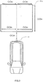
- the imaging section 1, provided as an imaging means, is constituted by, for example, as shown in FIG.2 , one camera 11 installed in a front part of the subject vehicle, two cameras 12 and 13 installed in the left and right side mirrors of the subject vehicle, and one camera installed in a rear part of the subject vehicle.
- the front camera 11 takes images of the front of the subject vehicle.
- the side cameras 12 and 13 take images of the side of the vehicle.
- the rear camera 14 takes images of the rear (for example, near the number plate or emblem), or, if installed in an uppermost part, takes images behind the subject vehicle. Additional cameras may be installed in corner parts of the vehicle, in the back of the rear-view mirror, or elsewhere.
- the installation position, the installation angle, and the kind of the lens are set for each individual camera to be installed.
- the detection area setting section 2, imaging parameter setting section 3, obstacle detection section 4 and synthesized data generating section 5 are implemented by executing a software program in an electronic control unit (ECU) 100 installed in the subject vehicle.
- the control apparatus according to the present embodiment is formed by combining at least the detection area setting section 2, obstacle detection section 4 and synthesized data generating section 5.
- the detection area setting section 2 provided as a setting means, sets an obstacle detection area in the photographing range of the imaging section 1. That is to say, a detection area that can be set up may be the same as the photographing range or may be part of the photographing range.
- the detection area setting section 2 inputs detection area data showing the detection area having been set, to the obstacle detection section 4 and synthesized data generating section 5.
- the detection area data represents, for example, a group of coordinates to define the detection area.
- a method of inputting specific numerical values is a possible setting method.
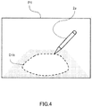
- FIG.4 there is a method of directly specifying detection area D1b on displayed photographed image P1 using penlight 2a and so forth.
- the detection area may be comprised of a plurality of discrete areas.
- a detection area is set using a different coordinate system from a photographed image, coordinate conversion needs to be performed for the detection area. This is necessary when, for example, a detection area is set by designating a relative position with respect to the subject vehicle, as shown in FIG.2 .
- a storage apparatus not shown.
- a method of converting three-dimensional coordinates of a detection area into two-dimensional coordinates of a photographed image using imaging parameters described later is another possible conversion method.
- external parameters such as the angle and position for setting a camera on a tripod and internal parameters such as the focal distance are known in advance, it is possible to use a general coordinate conversion method using a pinhole camera model.
- the imaging parameter setting section 3 sets, for example, installation parameters upon installing the imaging section 1 in the vehicle. To be more specific, the installation angle and installation position of a camera with respect to a vehicle, information for cutting an input image upon generating an output image (the angle of view, the number of pixels and so on), and various parameters for geometric transformation, are possible parameters.
- the imaging parameter setting section 3 inputs imaging parameters having been set, in the detection area setting section 2.
- the obstacle detection section 4 provided as a detection means, detects obstacles in a detection area set in a photographed image by means of image recognition processing using photographed data and detection area data received as input from imaging section 1 and detection area setting section 2, respectively.
- Various items of attribute information including the number, position, size, moving speed and moving direction of detected obstacles, may be reported as detection results.
- a method of image recognition processing that can be used for obstacle detection, there is background subtraction, whereby an obstacle is detected based on the level of aging of the image in a detection area. Furthermore, a method of storing the pattern of a detection target object in a storage apparatus (not shown) as learning data and searching for an area that matches or resembles the learning data in an input image, can be also used. Even other techniques of image recognition processing are also possible, including a method of using moving object recognition following an optical flow, a method of using a three-dimensional object recognition using a stereo method, and a method combining these. The image recognition processing technique to use can be selected depending on system configurations.
- the synthesized data generating 5 provided as a processing means, performs image processing to generate display data for drawing a superimposing detection area on a display image, using detection area data received as input from the detection area setting section 2 and photographed data received as input from the imaging section 1. That is to say the synthesized data generating section 5 synthesizes a photographed image with a display object that makes the detection area visible (for example, a line to define the outer edges of the detection area). Display data therefore refers to data to show a synthesized image.
- the synthesized data generating section 5 inputs display data having been generated, in the display section 6.
- the warning section 7 issues a warning based on an obstacle detection result in the obstacle detection section 4.
- the warning section 7 issues a warning to inform the driver of the presence of the obstacle.
- the kinds of warnings that can be use include sound, voice and light, and these can be changed as appropriate depending on the situation.
- the display section 6, provided as a display means, is a display apparatus such as, for example, a liquid-crystal display apparatus.
- a dedicated in-vehicle monitor or a general television monitor can be used, for example.
- the display section 6 displays images based on display data received as input from the synthesized data generating section 5.
- the content to be displayed is a result of combining a detection result in the obstacle detection section 4, a detection area set up in the detection area setting section 2, and an input image photographed in the imaging section 1.
- the display apparatus used as the display section 6, should preferably have touch-panel functions that make possible input operations for specifying the detection area.
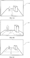
- detection area D1d is emphasized by drawing (painting) the inside of detection area D1d by a transparent color.
- the boundary parts here may be shown by broken lines as shown in FIG.6 or by solid lines as shown in FIG.7 , or other kinds of lines may be used as well.
- display image P3 in the event detected obstacle O and detection area D1d are displayed together, in the objects displayed to identify detection area D1a (drawings of lines and transparent color), parts where the coordinate positions overlap with obstacle O, are not drawn. By this means, the presence of obstacle O on an image can be emphasized.
- mark M is displayed in the position of obstacle O.
- obstacle O can be emphasized even more on an image, so that it is possible to inform the driver of the risk of collision, reliably, in a visual fashion.
- warning message W is displayed above display image P4. In this case, too, it is possible to inform the driver of the risk of collision, reliably, in a visual fashion.
- FIG.10 A case will be described here where detection area coordinate conversion is performed using imaging parameters.
- an image is taken in the imaging section 1 in step S1
- a detection area is specified in the detection area setting section 2 in step S2
- imaging parameters are set in the imaging parameter setting section 3 in step S3.
- step 4 in the detection area setting section 2, three-dimensional coordinates of the detection area are converted into image coordinates on an input image, using external parameters in the imaging parameters. This conversion is calculated based on, for example, a pinhole camera model used in general camera image conversion.
- step S5 in the synthesized data generating section 5, based on an input image and the detection area subjected to coordinate conversion in S4, the detection area is superimposed upon the input image. The method of this superimposition uses frame display/painting, broken lines/solid lines, and so forth, as described earlier.
- step S6 synthesized data generating section 5 converts the input image on which a detection area is superimposed, into an output image for display.
- the input image is converted into an output image based on information related to cutting, in the imaging parameters.
- display image P6 FIG.11B
- image P7 of a wider range FIG.11C
- a detection area is superimposed on the input image and needs not be recalculated in accordance with the output image. Consequently, it is possible to support, at ease, cases where the display image changes depending on applications.
- image processing for surrounding an area subject to obstacle detection i.e. detection area
- a display image by frames or painting the area by a transparent color is performed, so that the detection area is shown to the driver with a photographed image, distinctly, in a visual fashion. Consequently, even when detection fails or is missed during obstacle detection processing, the deriver is prevented from unnecessary confusion.
- the drive is able to judge at ease whether a pedestrian is outside the detection area or the system is malfunctioning.
- the vehicle surrounding monitoring apparatus of embodiment 2 of the present invention will be described now.
- the vehicle surrounding monitoring apparatus of this embodiment has basically the same configuration as the above embodiment. Therefore, the same components as those of the above embodiment described earlier, will be assigned the same reference numerals and will not be described in detail.
- the vehicle surrounding monitoring apparatus of the present embodiment has a configuration adding a detection area operation input section 201 to the configuration described in embodiment 1, as shown in FIG.12 .
- the detection area setting section 2, imaging parameter setting section 3, obstacle detection section 4, synthesized data generating section 5 and detection area operation input section 201 are implemented by executing a software program in an ECU 200 installed in the subject vehicle.
- the setting means is constituted by combining the detection area setting section 2 and detection area operation input section 201
- the control apparatus according to the present embodiment is constituted by combining at least the detection area setting section 2, detection area operation input section 201, obstacle detection section 4 and synthesized data generating section 5.
- the detection area operation input section 201 receives an operation input for changing the detection area set in the detection area setting section 2, and has this input reflected in the detection area setting. Operation input reception is made possible by, for example, displaying touch panel switch SW that is operable, in display image P8, on a display apparatus having touch panel functions, as shown in FIG.13 , and receiving a signal showing a touch panel switch SW operation result, from the display apparatus. For example, if the driver operates touch panel switch SW, original detection area D2a can be changed on an arbitrary basis to, for example, enlarged detection area D2b or reduced detection area D2c. Furthermore, by operations of pressing touch panel switch SW, original detection area D2a can be moved up, down, left and right, on an arbitrary basis.
- the detection area can be set up on a variable basis, according to operation inputs from the monitoring party (e.g. driver).
- the actual detection area can reflect the area the monitoring party wants to monitor, thereby improving the usability for the monitoring party even more.
- a detection area that is displayed can be operated on a display image, thereby allowing the monitoring party to perform changing operations at ease.
- the vehicle surrounding monitoring apparatus of embodiment 3 of the present invention will be described now.
- the vehicle surrounding monitoring apparatus of the present embodiment has basically the same configuration as the above embodiments. Therefore, the same components as those of the above embodiments described earlier, will be assigned the same reference numerals and will not be described in detail.
- the vehicle surrounding monitoring apparatus of the present embodiment has a configuration adding a driving state information acquiring section 301 to the configuration described in embodiment 1, as shown in FIG.14 .
- the detection area setting section 2, imaging parameter setting section 3, obstacle detection section 4, synthesized data generating section 5 and driving state information acquiring section 301 are implemented by executing a software program in an ECU 300 installed in the subject vehicle.
- the setting means is constituted by combining the detection area setting section 2 and traveling state information acquiring section 301
- the control apparatus according to the present embodiment is constituted by combining at least the detection area setting section 2, traveling state information acquiring section 301, obstacle detection section 4 and synthesized data generating section 5.
- the driving state information acquiring section 301 acquires a subject vehicle driving state detection result as driving state information.
- the driving sate information acquiring section 301 has this detected driving state in the obstacle detection area setting.
- This driving state information refers to, for example, information showing physical quantities in the driving state.
- Examples of physical quantities to show the driving state include, for example, driving speed and traveling direction.
- Means that can be used to measure the traveling direction include, for example, a steering angle sensor and an angular velocity sensor, and means that can be used to measure the driving speed include, for example, a vehicle speed meter and accelerometer.
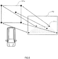
- FIG.15 shows an example of variation of a detection area according to a driving state having been detected. While the subject vehicle is moving backward straight, detection area D3a that extends straight along the path is set. If the steering wheel is turned to the right while the subject vehicle is moving backward (in FIG.15 , the subject vehicle is shown from above, so that the arrow to show the state of the steering wheel ST turns to the left), curved detection area D3b is set up along a path predicted from that turning of the steering wheel.
- the obstacle detection area can be adjusted according the turning of the steering wheel.
- the detection area can be set on an arbitrary basis by, for example, confining the obstacle detection area to a nearby area of the subject vehicle when the driving speed is slower, and extending the obstacle detection area further when the driving speed is faster.
- the driving speed can be acquired as a state of driving, it is possible to adjust the obstacle detection area according to the traveling speed.
- the present embodiment it is possible to optimize the detection obstacle detection area for the driving state of the subject vehicle. Furthermore, an optimized detection area is displayed on the display section 6, and the monitoring party can see and check it.
- the vehicle surrounding monitoring apparatus of embodiment 4 of the present invention will be described now.
- the vehicle surrounding monitoring apparatus of this embodiment has basically the same configuration as the above embodiments. Therefore, the same components as those of the above embodiments described earlier, will be assigned the same reference numerals and will not be described in detail.
- the vehicle surrounding monitoring apparatus of the present embodiment has a configuration adding a photographing environment information acquiring section 401, to the configuration described in embodiment 1, as shown in FIG.16 .
- the detection area setting section 2, imaging parameter setting section 3, obstacle detection section 4, synthesized data generating section 5 and photographing environment information acquiring section 401 are implemented by executing a software program in an ECU 400 installed in the subject vehicle.
- the setting means is constituted by combining the detection area setting section 2 and photographing environment information acquiring section 401
- the control apparatus according to the present embodiment is constituted by combining at least the detection area setting section 2, photographing environment information acquiring section 401, obstacle detection section 4 and synthesized data generating section 5.
- the photographing environment information acquiring section 401 acquires photographing environment detection results as photographing environment information. Then, the photographing environment information acquiring section 401 has this detected photographing environment in the obstacle detection area setting.
- This photographing environment information refers to information showing external environmental conditions of the subject vehicle.
- an illuminance sensor or a means for sensing the brightness in the external environment from time information and switching information of the subject vehicle's lights is provided in the subject vehicle, this detection result is acquired as photographing environment information.
- a raindrop sensor, image sensor, radar sensor and other appropriate information communications means that can detect the occurrence of rainfall, snowfall and fog are provided in the subject vehicle, these detection results are acquired as photographing environment information.
- the obstacle detection area can be changed depending on the photographing environment detected. That is, the detection area can be set on an arbitrary basis by, for example, confining the obstacle detection area to a nearby area of the subject vehicle when it is darker around subject vehicle, and extending the obstacle detection area further when it is brighter around the subject vehicle. For example, also in the event of the occurrence of rainfall or fog, the obstacle detection area may be confined to a nearby area of the subject vehicle. By this means, the accuracy of obstacle detection can be maintained at a certain level or above regardless of the photographing environment.
- an optimized detection area is displayed on the display section 6, and the monitoring party can see and check it.
- the vehicle surrounding monitoring apparatus of embodiment 5 of the present invention will be described now.
- the vehicle surrounding monitoring apparatus of this embodiment has basically the same configuration as the above embodiments. Therefore, the same components as those of the above embodiments described earlier, will be assigned the same reference numerals and will not be described in detail.
- the vehicle surrounding monitoring apparatus of the present embodiment has a configuration adding a map information acquiring section 501 to the configuration described in embodiment 1, as shown in FIG.17 .
- the detection area setting section 2, imaging parameter setting section 3, obstacle detection section 4, synthesized data generating section 5 and map information acquiring section 501 are implemented by executing a software program in an ECU 500 installed in the subject vehicle.
- the setting means is constituted by combining the detection area setting section 2 and map information acquiring section 501
- the control apparatus according to the present embodiment is constituted by combining at least the detection area setting section 2, map information acquiring section 501, obstacle detection section 4 and synthesized data generating section 5.
- the map information acquiring section 501 acquires map information of the surroundings of the subject vehicle.
- the map information acquiring section 501 has this acquired map information in the obstacle detection area setting.
- This map information here includes various items of information that can be acquired using a car-navigation system or other appropriate radio communications means, such as the form of roads (e.g. intersections), road signs (e.g. pedestrian crossing) and facility attributes (e.g. grade school).
- roads e.g. intersections
- road signs e.g. pedestrian crossing
- facility attributes e.g. grade school
- FIG.18 shows an example of variation of a detection area according to map information having been acquired. While the subject vehicle is driving on a straight road, detection area D5a that is extended straight is set in display image P9, to match the form of that road. If map information having been acquired reveals that there is a T junction ahead of the traveling road, detection area D5b is set in a modified or enlarged shape to match the form of the T junction.
- the obstacle detection area can be adjusted according the turning of the steering wheel.
- the detection obstacle detection area based on map information of the surroundings of the vehicle. Furthermore, an optimized detection area is displayed on the display section 6, and the monitoring party can see and check it.
- Embodiments of the present invention have been described above.
- the above embodiments can be implemented with various changes.
- the above embodiments can also be implemented in various combinations.
- the control apparatus of the present invention provides an advantage of improving the usability of a vehicle surrounding monitoring apparatus without confusing the monitoring party while monitoring the surroundings of a vehicle, and is applicable to a vehicle surrounding monitoring apparatus.
Landscapes
- Physics & Mathematics (AREA)
- General Physics & Mathematics (AREA)
- Engineering & Computer Science (AREA)
- Multimedia (AREA)
- Theoretical Computer Science (AREA)
- Signal Processing (AREA)
- Closed-Circuit Television Systems (AREA)
- Traffic Control Systems (AREA)
Claims (8)
- Appareil de contrôle utilisé pour surveiller les alentours d'un véhicule, comprenant :une section de réglage de paramètres d'imagerie (3) adaptée pour régler des paramètres d'imagerie, qui sont des paramètres d'installation d'une section d'imagerie (1) installée dans un véhicule ;une section de réglage de surface de détection (2) adaptée pour régler, sur base des paramètres d'imagerie, une surface de détection (D1a) soumise à une détection d'obstacle dans une plage de photographie de la section d'imagerie (1) conformément à un résultat de détection d'un état de conduite du véhicule ;une section de détection d'obstacle (4) adaptée pour détecter un obstacle dans la surface de détection (D1a) déterminée dans une image prise par la section d'imagerie (1) ; etune section de génération de données synthétisées (5) adaptée pour mettre en œuvre un traitement d'image pour générer des données d'affichage pour dessiner une surface de détection par surimposition sur une image d'affichage, un utilisant des données de surface de détection reçues de la section de réglage de surface de détection (2) et des données de photographie reçues de la section d'imagerie (1) ;dans lequel :l'état de conduite du véhicule comprend l'état d'un volant de direction du véhicule ; etla section de réglage de surface de détection (2) est adaptée pour régler la surface de détection d'obstacle (D1a) selon une trajectoire du véhicule prédite à partir de l'état détecté de l'état du volant de direction.
- Appareil de contrôle selon la revendication 1, dans lequel :la section de réglage de surface de détection (2) est adaptée pour régler la surface de détection d'obstacle (D1a) sur une base variable dans la plage de photographie ; etla plage de photographie présente un angle fixe par rapport au véhicule pendant que la section d'imagerie (1) photographie des images.
- Appareil de contrôle selon la revendication 1, dans lequel :
la section de réglage de surface de détection (2) est en outre adaptée pour régler la surface de détection d'obstacle (D1a) variable sur une base variable conformément à une opération d'entrée. - Appareil de contrôle selon la revendication 1, dans lequel :l'état de conduite du véhicule comprend en outre la vitesse de conduite du véhicule ; etla section de réglage de surface de détection (2) est en outre adaptée pour changer la surface de détection d'obstacle (D1a) de telle sorte que la surface de détection (D1a) est augmentée quand la vitesse de conduite est plus élevée.
- Appareil de contrôle selon la revendication 1, dans lequel :
la section de réglage de surface de détection (2) est en outre adaptée pour régler la surface de détection d'obstacle (D1a) sur une base variable conformément à un résultat de détection d'un environnement externe du véhicule. - Appareil de contrôle selon la revendication 1, dans lequel :
la section de réglage de surface de détection (2) est en outre adaptée pour régler la surface de détection d'obstacle (D1a) sur une base variable en utilisant de l'information cartographique des alentours du véhicule. - Appareil de contrôle selon la revendication 6, dans lequel :l'information cartographique comprend de l'information pour spécifier la forme d'une route qui existe sur une trajectoire du véhicule ; etla section de réglage de surface de détection (2) est en outre adaptée pour régler la surface de détection d'obstacle (D1a) conformément à la forme spécifiée de la route.
- Appareil de surveillance des alentours d'un véhicule, comprenant
un appareil de contrôle selon l'une quelconque des revendications 1 à 7 ;
une section d'imagerie (2) ; et
une section d'affichage (6).
Applications Claiming Priority (2)
| Application Number | Priority Date | Filing Date | Title |
|---|---|---|---|
| JP2009233321 | 2009-10-07 | ||
| PCT/JP2010/001959 WO2011043006A1 (fr) | 2009-10-07 | 2010-03-18 | Dispositif de commande et dispositif de surveillance des abords d'un véhicule |
Publications (3)
| Publication Number | Publication Date |
|---|---|
| EP2487906A1 EP2487906A1 (fr) | 2012-08-15 |
| EP2487906A4 EP2487906A4 (fr) | 2016-10-26 |
| EP2487906B1 true EP2487906B1 (fr) | 2020-05-27 |
Family
ID=43856492
Family Applications (1)
| Application Number | Title | Priority Date | Filing Date |
|---|---|---|---|
| EP10781580.5A Active EP2487906B1 (fr) | 2009-10-07 | 2010-03-18 | Dispositif de commande et dispositif de surveillance des abords d'un véhicule |
Country Status (4)
| Country | Link |
|---|---|
| US (1) | US20110228980A1 (fr) |
| EP (1) | EP2487906B1 (fr) |
| JP (1) | JP5143235B2 (fr) |
| WO (1) | WO2011043006A1 (fr) |
Families Citing this family (27)
| Publication number | Priority date | Publication date | Assignee | Title |
|---|---|---|---|---|
| US9524094B2 (en) | 2009-02-20 | 2016-12-20 | Nokia Technologies Oy | Method and apparatus for causing display of a cursor |
| US9073484B2 (en) * | 2010-03-03 | 2015-07-07 | Honda Motor Co., Ltd. | Surrounding area monitoring apparatus for vehicle |
| JP2011205513A (ja) * | 2010-03-26 | 2011-10-13 | Aisin Seiki Co Ltd | 車両周辺監視装置 |
| JP5626147B2 (ja) | 2011-07-04 | 2014-11-19 | 株式会社デンソー | 車両接近物検知装置 |
| US20150116495A1 (en) * | 2012-06-08 | 2015-04-30 | Hitachi Construction Machinery Co., Ltd. | Display device for self-propelled industrial machine |
| RU2571368C1 (ru) * | 2012-07-27 | 2015-12-20 | Ниссан Мотор Ко., Лтд. | Устройство обнаружения трехмерных объектов, способ обнаружения трехмерных объектов |
| KR101896715B1 (ko) * | 2012-10-31 | 2018-09-07 | 현대자동차주식회사 | 주변차량 위치 추적 장치 및 방법 |
| DE102013200387A1 (de) | 2013-01-14 | 2014-07-17 | Robert Bosch Gmbh | Erstellung einer Hinderniskarte |
| JP2014191485A (ja) * | 2013-03-26 | 2014-10-06 | Sharp Corp | 障害物検出装置、及びそれを備えた電動車両 |
| JP6191241B2 (ja) | 2013-05-30 | 2017-09-06 | ソニー株式会社 | 情報処理装置、情報処理方法、及びプログラム |
| DE202013006676U1 (de) * | 2013-07-25 | 2014-10-28 | GM Global Technology Operations LLC (n. d. Ges. d. Staates Delaware) | System zur Warnung vor einer möglichen Kollision einesKraftfahrzeuges mit einem Objekt |
| JP6388205B2 (ja) * | 2014-02-25 | 2018-09-12 | パナソニックIpマネジメント株式会社 | 表示制御プログラム、表示制御装置、および表示装置 |
| EP3136367B1 (fr) * | 2015-08-31 | 2022-12-07 | Continental Autonomous Mobility Germany GmbH | Dispositif de camera de vehicule et procede de detection d'une zone environnante arriere d'un vehicule automobile |
| JP6699665B2 (ja) | 2015-09-08 | 2020-05-27 | ソニー株式会社 | 情報処理装置、情報処理方法及びプログラム |
| WO2017094626A1 (fr) * | 2015-11-30 | 2017-06-08 | 住友重機械工業株式会社 | Système de surveillance de périphérie pour engin de chantier |
| JP6805716B2 (ja) * | 2016-01-25 | 2020-12-23 | 株式会社Jvcケンウッド | 表示装置、表示方法、プログラム |
| CN107179767B (zh) * | 2016-03-10 | 2021-10-08 | 松下电器(美国)知识产权公司 | 驾驶控制装置、驾驶控制方法以及非瞬时性记录介质 |
| JP6727946B2 (ja) * | 2016-06-20 | 2020-07-22 | 京セラ株式会社 | 車両用カメラモニタシステム及び車両 |
| EP3293717B1 (fr) * | 2016-09-08 | 2021-11-10 | KNORR-BREMSE Systeme für Nutzfahrzeuge GmbH | Système de freinage à commande électronique |
| JP7233162B2 (ja) | 2017-12-18 | 2023-03-06 | キヤノン株式会社 | 撮像装置及びその制御方法、プログラム、記憶媒体 |
| CN114827458A (zh) | 2017-12-18 | 2022-07-29 | 佳能株式会社 | 摄像设备及其控制方法和存储介质 |
| JP2019179511A (ja) * | 2018-03-30 | 2019-10-17 | パナソニックIpマネジメント株式会社 | 運転支援システム、情報処理装置及び運転支援方法 |
| KR102212229B1 (ko) | 2018-11-07 | 2021-02-05 | 삼성전자주식회사 | 이동체에 포함된 카메라 시스템 및 그 제어방법. |
| JP7268616B2 (ja) * | 2020-01-30 | 2023-05-08 | いすゞ自動車株式会社 | 報知装置 |
| JP6987173B2 (ja) * | 2020-04-22 | 2021-12-22 | 三菱電機株式会社 | 障害物検知装置及びこれを備えた障害物検知システム、障害物検知方法 |
| JP7273084B2 (ja) * | 2021-03-22 | 2023-05-12 | 名古屋電機工業株式会社 | 障害物検知装置、障害物検知方法およびプログラム |
| KR102457747B1 (ko) * | 2022-05-27 | 2022-10-24 | 주식회사 뉴이스트원테크 | 레이더 기반 후방 감지 시스템 및 이의 동작 방법 |
Family Cites Families (17)
| Publication number | Priority date | Publication date | Assignee | Title |
|---|---|---|---|---|
| IT1240974B (it) * | 1990-07-05 | 1993-12-27 | Fiat Ricerche | Metodo e apparecchiatura per evitare la collisione di un autoveicolo contro ostacoli. |
| JPH04311186A (ja) | 1991-04-10 | 1992-11-02 | Toshiba Corp | 画像監視装置 |
| JP3183284B2 (ja) * | 1999-01-19 | 2001-07-09 | 株式会社豊田自動織機製作所 | 車両の後退時の操舵支援装置 |
| US7366595B1 (en) * | 1999-06-25 | 2008-04-29 | Seiko Epson Corporation | Vehicle drive assist system |
| DE60105684T2 (de) * | 2000-04-05 | 2005-02-10 | Matsushita Electric Industrial Co., Ltd., Kadoma | System und Verfahren zur Fahrerunterstützung |
| ATE311725T1 (de) * | 2001-09-07 | 2005-12-15 | Matsushita Electric Ind Co Ltd | Vorrichtung zum anzeigen der umgebung eines fahrzeuges und system zur bildbereitstellung |
| JP3922201B2 (ja) * | 2003-03-26 | 2007-05-30 | 松下電工株式会社 | 車載用視界モニタシステム |
| JP4239689B2 (ja) * | 2003-05-30 | 2009-03-18 | スズキ株式会社 | 車両用警報システム及び車両用警報発生方法 |
| JP4052650B2 (ja) * | 2004-01-23 | 2008-02-27 | 株式会社東芝 | 障害物検出装置、方法及びプログラム |
| DE102004047481A1 (de) * | 2004-09-30 | 2006-04-13 | Robert Bosch Gmbh | Verfahren zur Anzeige eines Fahrzeugfahrraums |
| US8130269B2 (en) * | 2005-03-23 | 2012-03-06 | Aisin Aw Co., Ltd. | Visual recognition apparatus, methods, and programs for vehicles |
| JP2008179940A (ja) * | 2005-03-31 | 2008-08-07 | Hitachi Constr Mach Co Ltd | 作業機械の周囲監視装置 |
| JP4400584B2 (ja) * | 2006-03-01 | 2010-01-20 | トヨタ自動車株式会社 | 障害物検出方法及び障害物検出装置 |
| JP5294562B2 (ja) | 2007-01-18 | 2013-09-18 | クラリオン株式会社 | 車両周辺監視装置、その表示方法 |
| JP2008271266A (ja) * | 2007-04-23 | 2008-11-06 | Matsushita Electric Ind Co Ltd | 表示制御装置、方法およびプログラム |
| JP2009147906A (ja) * | 2007-11-19 | 2009-07-02 | Autonetworks Technologies Ltd | 車両周辺監視装置 |
| JP5258624B2 (ja) | 2008-03-06 | 2013-08-07 | 洋左右 前嶋 | 両面畳み対応の折畳み装置 |
-
2010
- 2010-03-18 JP JP2010533152A patent/JP5143235B2/ja not_active Expired - Fee Related
- 2010-03-18 EP EP10781580.5A patent/EP2487906B1/fr active Active
- 2010-03-18 WO PCT/JP2010/001959 patent/WO2011043006A1/fr active Application Filing
- 2010-03-18 US US12/994,605 patent/US20110228980A1/en not_active Abandoned
Non-Patent Citations (1)
| Title |
|---|
| None * |
Also Published As
| Publication number | Publication date |
|---|---|
| EP2487906A4 (fr) | 2016-10-26 |
| WO2011043006A1 (fr) | 2011-04-14 |
| JP5143235B2 (ja) | 2013-02-13 |
| JPWO2011043006A1 (ja) | 2013-02-28 |
| US20110228980A1 (en) | 2011-09-22 |
| EP2487906A1 (fr) | 2012-08-15 |
Similar Documents
| Publication | Publication Date | Title |
|---|---|---|
| EP2487906B1 (fr) | Dispositif de commande et dispositif de surveillance des abords d'un véhicule | |
| JP6801787B2 (ja) | 駐車支援方法及び駐車支援装置 | |
| JP6346614B2 (ja) | 情報表示システム | |
| US8878934B2 (en) | Image display device | |
| RU2675719C1 (ru) | Устройство и способ отображения транспортного средства | |
| JP6413207B2 (ja) | 車両用表示装置 | |
| JP5099451B2 (ja) | 車両周辺確認装置 | |
| JP6311646B2 (ja) | 画像処理装置、電子ミラーシステム、及び画像処理方法 | |
| KR102000929B1 (ko) | 차량을 위한 미러 대체 시스템 | |
| US20150109444A1 (en) | Vision-based object sensing and highlighting in vehicle image display systems | |
| US20080198226A1 (en) | Image Processing Device | |
| JP5136950B2 (ja) | 車載機器の操作装置 | |
| JP4943367B2 (ja) | 車両用情報表示装置 | |
| JP5942979B2 (ja) | 車両用情報表示装置及び車両用情報表示方法 | |
| JP2017144889A (ja) | 車載装置、車載装置の制御方法及び車載装置の制御プログラム | |
| JP7077616B2 (ja) | 表示制御装置および表示制御方法 | |
| JP7006460B2 (ja) | 車両用表示制御装置、車両用表示システム、車両用表示制御方法、およびプログラム | |
| KR102130059B1 (ko) | 디지털 백미러 제어 유닛 및 방법 | |
| JP2008222153A (ja) | 合流支援装置 | |
| JP2018182646A (ja) | 画像表示装置 | |
| JP7047586B2 (ja) | 車両用表示制御装置 | |
| JP6448714B2 (ja) | 情報表示システム | |
| JP2012153256A (ja) | 画像処理装置 | |
| JP2007025739A (ja) | 車両用画像表示装置 | |
| JP2020140603A (ja) | 表示制御装置、表示制御方法、および表示制御プログラム |
Legal Events
| Date | Code | Title | Description |
|---|---|---|---|
| PUAI | Public reference made under article 153(3) epc to a published international application that has entered the european phase |
Free format text: ORIGINAL CODE: 0009012 |
|
| 17P | Request for examination filed |
Effective date: 20120301 |
|
| AK | Designated contracting states |
Kind code of ref document: A1 Designated state(s): AT BE BG CH CY CZ DE DK EE ES FI FR GB GR HR HU IE IS IT LI LT LU LV MC MK MT NL NO PL PT RO SE SI SK SM TR |
|
| DAX | Request for extension of the european patent (deleted) | ||
| RAP1 | Party data changed (applicant data changed or rights of an application transferred) |
Owner name: PANASONIC INTELLECTUAL PROPERTY MANAGEMENT CO., LT |
|
| RAP1 | Party data changed (applicant data changed or rights of an application transferred) |
Owner name: PANASONIC INTELLECTUAL PROPERTY MANAGEMENT CO., LT |
|
| RA4 | Supplementary search report drawn up and despatched (corrected) |
Effective date: 20160926 |
|
| RIC1 | Information provided on ipc code assigned before grant |
Ipc: H04N 7/18 20060101AFI20160920BHEP Ipc: G06K 9/00 20060101ALI20160920BHEP Ipc: B60R 1/00 20060101ALI20160920BHEP Ipc: G08G 1/16 20060101ALI20160920BHEP |
|
| RIC1 | Information provided on ipc code assigned before grant |
Ipc: H04N 7/18 20060101AFI20190702BHEP Ipc: G08G 1/16 20060101ALI20190702BHEP Ipc: G06K 9/00 20060101ALI20190702BHEP Ipc: B60R 1/00 20060101ALI20190702BHEP |
|
| STAA | Information on the status of an ep patent application or granted ep patent |
Free format text: STATUS: EXAMINATION IS IN PROGRESS |
|
| 17Q | First examination report despatched |
Effective date: 20190925 |
|
| GRAP | Despatch of communication of intention to grant a patent |
Free format text: ORIGINAL CODE: EPIDOSNIGR1 |
|
| STAA | Information on the status of an ep patent application or granted ep patent |
Free format text: STATUS: GRANT OF PATENT IS INTENDED |
|
| INTG | Intention to grant announced |
Effective date: 20200129 |
|
| GRAS | Grant fee paid |
Free format text: ORIGINAL CODE: EPIDOSNIGR3 |
|
| GRAA | (expected) grant |
Free format text: ORIGINAL CODE: 0009210 |
|
| STAA | Information on the status of an ep patent application or granted ep patent |
Free format text: STATUS: THE PATENT HAS BEEN GRANTED |
|
| AK | Designated contracting states |
Kind code of ref document: B1 Designated state(s): AT BE BG CH CY CZ DE DK EE ES FI FR GB GR HR HU IE IS IT LI LT LU LV MC MK MT NL NO PL PT RO SE SI SK SM TR |
|
| REG | Reference to a national code |
Ref country code: GB Ref legal event code: FG4D |
|
| REG | Reference to a national code |
Ref country code: CH Ref legal event code: EP |
|
| REG | Reference to a national code |
Ref country code: DE Ref legal event code: R096 Ref document number: 602010064466 Country of ref document: DE |
|
| REG | Reference to a national code |
Ref country code: AT Ref legal event code: REF Ref document number: 1275797 Country of ref document: AT Kind code of ref document: T Effective date: 20200615 |
|
| REG | Reference to a national code |
Ref country code: LT Ref legal event code: MG4D |
|
| PG25 | Lapsed in a contracting state [announced via postgrant information from national office to epo] |
Ref country code: IS Free format text: LAPSE BECAUSE OF FAILURE TO SUBMIT A TRANSLATION OF THE DESCRIPTION OR TO PAY THE FEE WITHIN THE PRESCRIBED TIME-LIMIT Effective date: 20200927 Ref country code: NO Free format text: LAPSE BECAUSE OF FAILURE TO SUBMIT A TRANSLATION OF THE DESCRIPTION OR TO PAY THE FEE WITHIN THE PRESCRIBED TIME-LIMIT Effective date: 20200827 Ref country code: GR Free format text: LAPSE BECAUSE OF FAILURE TO SUBMIT A TRANSLATION OF THE DESCRIPTION OR TO PAY THE FEE WITHIN THE PRESCRIBED TIME-LIMIT Effective date: 20200828 Ref country code: LT Free format text: LAPSE BECAUSE OF FAILURE TO SUBMIT A TRANSLATION OF THE DESCRIPTION OR TO PAY THE FEE WITHIN THE PRESCRIBED TIME-LIMIT Effective date: 20200527 Ref country code: SE Free format text: LAPSE BECAUSE OF FAILURE TO SUBMIT A TRANSLATION OF THE DESCRIPTION OR TO PAY THE FEE WITHIN THE PRESCRIBED TIME-LIMIT Effective date: 20200527 Ref country code: FI Free format text: LAPSE BECAUSE OF FAILURE TO SUBMIT A TRANSLATION OF THE DESCRIPTION OR TO PAY THE FEE WITHIN THE PRESCRIBED TIME-LIMIT Effective date: 20200527 Ref country code: PT Free format text: LAPSE BECAUSE OF FAILURE TO SUBMIT A TRANSLATION OF THE DESCRIPTION OR TO PAY THE FEE WITHIN THE PRESCRIBED TIME-LIMIT Effective date: 20200928 |
|
| REG | Reference to a national code |
Ref country code: NL Ref legal event code: MP Effective date: 20200527 |
|
| PG25 | Lapsed in a contracting state [announced via postgrant information from national office to epo] |
Ref country code: BG Free format text: LAPSE BECAUSE OF FAILURE TO SUBMIT A TRANSLATION OF THE DESCRIPTION OR TO PAY THE FEE WITHIN THE PRESCRIBED TIME-LIMIT Effective date: 20200827 Ref country code: HR Free format text: LAPSE BECAUSE OF FAILURE TO SUBMIT A TRANSLATION OF THE DESCRIPTION OR TO PAY THE FEE WITHIN THE PRESCRIBED TIME-LIMIT Effective date: 20200527 Ref country code: LV Free format text: LAPSE BECAUSE OF FAILURE TO SUBMIT A TRANSLATION OF THE DESCRIPTION OR TO PAY THE FEE WITHIN THE PRESCRIBED TIME-LIMIT Effective date: 20200527 |
|
| REG | Reference to a national code |
Ref country code: AT Ref legal event code: MK05 Ref document number: 1275797 Country of ref document: AT Kind code of ref document: T Effective date: 20200527 |
|
| PG25 | Lapsed in a contracting state [announced via postgrant information from national office to epo] |
Ref country code: NL Free format text: LAPSE BECAUSE OF FAILURE TO SUBMIT A TRANSLATION OF THE DESCRIPTION OR TO PAY THE FEE WITHIN THE PRESCRIBED TIME-LIMIT Effective date: 20200527 |
|
| PG25 | Lapsed in a contracting state [announced via postgrant information from national office to epo] |
Ref country code: DK Free format text: LAPSE BECAUSE OF FAILURE TO SUBMIT A TRANSLATION OF THE DESCRIPTION OR TO PAY THE FEE WITHIN THE PRESCRIBED TIME-LIMIT Effective date: 20200527 Ref country code: ES Free format text: LAPSE BECAUSE OF FAILURE TO SUBMIT A TRANSLATION OF THE DESCRIPTION OR TO PAY THE FEE WITHIN THE PRESCRIBED TIME-LIMIT Effective date: 20200527 Ref country code: CZ Free format text: LAPSE BECAUSE OF FAILURE TO SUBMIT A TRANSLATION OF THE DESCRIPTION OR TO PAY THE FEE WITHIN THE PRESCRIBED TIME-LIMIT Effective date: 20200527 Ref country code: RO Free format text: LAPSE BECAUSE OF FAILURE TO SUBMIT A TRANSLATION OF THE DESCRIPTION OR TO PAY THE FEE WITHIN THE PRESCRIBED TIME-LIMIT Effective date: 20200527 Ref country code: SM Free format text: LAPSE BECAUSE OF FAILURE TO SUBMIT A TRANSLATION OF THE DESCRIPTION OR TO PAY THE FEE WITHIN THE PRESCRIBED TIME-LIMIT Effective date: 20200527 Ref country code: IT Free format text: LAPSE BECAUSE OF FAILURE TO SUBMIT A TRANSLATION OF THE DESCRIPTION OR TO PAY THE FEE WITHIN THE PRESCRIBED TIME-LIMIT Effective date: 20200527 Ref country code: EE Free format text: LAPSE BECAUSE OF FAILURE TO SUBMIT A TRANSLATION OF THE DESCRIPTION OR TO PAY THE FEE WITHIN THE PRESCRIBED TIME-LIMIT Effective date: 20200527 Ref country code: AT Free format text: LAPSE BECAUSE OF FAILURE TO SUBMIT A TRANSLATION OF THE DESCRIPTION OR TO PAY THE FEE WITHIN THE PRESCRIBED TIME-LIMIT Effective date: 20200527 |
|
| PG25 | Lapsed in a contracting state [announced via postgrant information from national office to epo] |
Ref country code: PL Free format text: LAPSE BECAUSE OF FAILURE TO SUBMIT A TRANSLATION OF THE DESCRIPTION OR TO PAY THE FEE WITHIN THE PRESCRIBED TIME-LIMIT Effective date: 20200527 Ref country code: SK Free format text: LAPSE BECAUSE OF FAILURE TO SUBMIT A TRANSLATION OF THE DESCRIPTION OR TO PAY THE FEE WITHIN THE PRESCRIBED TIME-LIMIT Effective date: 20200527 |
|
| REG | Reference to a national code |
Ref country code: DE Ref legal event code: R097 Ref document number: 602010064466 Country of ref document: DE |
|
| PLBE | No opposition filed within time limit |
Free format text: ORIGINAL CODE: 0009261 |
|
| STAA | Information on the status of an ep patent application or granted ep patent |
Free format text: STATUS: NO OPPOSITION FILED WITHIN TIME LIMIT |
|
| 26N | No opposition filed |
Effective date: 20210302 |
|
| PG25 | Lapsed in a contracting state [announced via postgrant information from national office to epo] |
Ref country code: SI Free format text: LAPSE BECAUSE OF FAILURE TO SUBMIT A TRANSLATION OF THE DESCRIPTION OR TO PAY THE FEE WITHIN THE PRESCRIBED TIME-LIMIT Effective date: 20200527 |
|
| PG25 | Lapsed in a contracting state [announced via postgrant information from national office to epo] |
Ref country code: MC Free format text: LAPSE BECAUSE OF FAILURE TO SUBMIT A TRANSLATION OF THE DESCRIPTION OR TO PAY THE FEE WITHIN THE PRESCRIBED TIME-LIMIT Effective date: 20200527 |
|
| REG | Reference to a national code |
Ref country code: CH Ref legal event code: PL |
|
| GBPC | Gb: european patent ceased through non-payment of renewal fee |
Effective date: 20210318 |
|
| REG | Reference to a national code |
Ref country code: BE Ref legal event code: MM Effective date: 20210331 |
|
| PG25 | Lapsed in a contracting state [announced via postgrant information from national office to epo] |
Ref country code: CH Free format text: LAPSE BECAUSE OF NON-PAYMENT OF DUE FEES Effective date: 20210331 Ref country code: LU Free format text: LAPSE BECAUSE OF NON-PAYMENT OF DUE FEES Effective date: 20210318 Ref country code: LI Free format text: LAPSE BECAUSE OF NON-PAYMENT OF DUE FEES Effective date: 20210331 Ref country code: IE Free format text: LAPSE BECAUSE OF NON-PAYMENT OF DUE FEES Effective date: 20210318 Ref country code: FR Free format text: LAPSE BECAUSE OF NON-PAYMENT OF DUE FEES Effective date: 20210331 Ref country code: GB Free format text: LAPSE BECAUSE OF NON-PAYMENT OF DUE FEES Effective date: 20210318 |
|
| PG25 | Lapsed in a contracting state [announced via postgrant information from national office to epo] |
Ref country code: BE Free format text: LAPSE BECAUSE OF NON-PAYMENT OF DUE FEES Effective date: 20210331 |
|
| PG25 | Lapsed in a contracting state [announced via postgrant information from national office to epo] |
Ref country code: HU Free format text: LAPSE BECAUSE OF FAILURE TO SUBMIT A TRANSLATION OF THE DESCRIPTION OR TO PAY THE FEE WITHIN THE PRESCRIBED TIME-LIMIT; INVALID AB INITIO Effective date: 20100318 Ref country code: CY Free format text: LAPSE BECAUSE OF FAILURE TO SUBMIT A TRANSLATION OF THE DESCRIPTION OR TO PAY THE FEE WITHIN THE PRESCRIBED TIME-LIMIT Effective date: 20200527 |
|
| PGFP | Annual fee paid to national office [announced via postgrant information from national office to epo] |
Ref country code: DE Payment date: 20220609 Year of fee payment: 14 |
|
| PG25 | Lapsed in a contracting state [announced via postgrant information from national office to epo] |
Ref country code: MK Free format text: LAPSE BECAUSE OF FAILURE TO SUBMIT A TRANSLATION OF THE DESCRIPTION OR TO PAY THE FEE WITHIN THE PRESCRIBED TIME-LIMIT Effective date: 20200527 |
|
| PG25 | Lapsed in a contracting state [announced via postgrant information from national office to epo] |
Ref country code: TR Free format text: LAPSE BECAUSE OF FAILURE TO SUBMIT A TRANSLATION OF THE DESCRIPTION OR TO PAY THE FEE WITHIN THE PRESCRIBED TIME-LIMIT Effective date: 20200527 |
|
| PG25 | Lapsed in a contracting state [announced via postgrant information from national office to epo] |
Ref country code: MT Free format text: LAPSE BECAUSE OF FAILURE TO SUBMIT A TRANSLATION OF THE DESCRIPTION OR TO PAY THE FEE WITHIN THE PRESCRIBED TIME-LIMIT Effective date: 20200527 |