EP2485848B1 - Düsenanordnung - Google Patents
Düsenanordnung Download PDFInfo
- Publication number
- EP2485848B1 EP2485848B1 EP10762872.9A EP10762872A EP2485848B1 EP 2485848 B1 EP2485848 B1 EP 2485848B1 EP 10762872 A EP10762872 A EP 10762872A EP 2485848 B1 EP2485848 B1 EP 2485848B1
- Authority
- EP
- European Patent Office
- Prior art keywords
- nozzle
- arrangement according
- nozzle arrangement
- lance
- coating material
- Prior art date
- Legal status (The legal status is an assumption and is not a legal conclusion. Google has not performed a legal analysis and makes no representation as to the accuracy of the status listed.)
- Not-in-force
Links
Images


Classifications
-
- B—PERFORMING OPERATIONS; TRANSPORTING
- B05—SPRAYING OR ATOMISING IN GENERAL; APPLYING FLUENT MATERIALS TO SURFACES, IN GENERAL
- B05B—SPRAYING APPARATUS; ATOMISING APPARATUS; NOZZLES
- B05B1/00—Nozzles, spray heads or other outlets, with or without auxiliary devices such as valves, heating means
- B05B1/14—Nozzles, spray heads or other outlets, with or without auxiliary devices such as valves, heating means with multiple outlet openings; with strainers in or outside the outlet opening
- B05B1/16—Nozzles, spray heads or other outlets, with or without auxiliary devices such as valves, heating means with multiple outlet openings; with strainers in or outside the outlet opening having selectively- effective outlets
- B05B1/1627—Nozzles, spray heads or other outlets, with or without auxiliary devices such as valves, heating means with multiple outlet openings; with strainers in or outside the outlet opening having selectively- effective outlets with a selecting mechanism comprising a gate valve, a sliding valve or a cock
- B05B1/1636—Nozzles, spray heads or other outlets, with or without auxiliary devices such as valves, heating means with multiple outlet openings; with strainers in or outside the outlet opening having selectively- effective outlets with a selecting mechanism comprising a gate valve, a sliding valve or a cock by relative rotative movement of the valve elements
-
- B—PERFORMING OPERATIONS; TRANSPORTING
- B05—SPRAYING OR ATOMISING IN GENERAL; APPLYING FLUENT MATERIALS TO SURFACES, IN GENERAL
- B05B—SPRAYING APPARATUS; ATOMISING APPARATUS; NOZZLES
- B05B13/00—Machines or plants for applying liquids or other fluent materials to surfaces of objects or other work by spraying, not covered by groups B05B1/00 - B05B11/00
- B05B13/06—Machines or plants for applying liquids or other fluent materials to surfaces of objects or other work by spraying, not covered by groups B05B1/00 - B05B11/00 specially designed for treating the inside of hollow bodies
- B05B13/0627—Arrangements of nozzles or spray heads specially adapted for treating the inside of hollow bodies
-
- B—PERFORMING OPERATIONS; TRANSPORTING
- B05—SPRAYING OR ATOMISING IN GENERAL; APPLYING FLUENT MATERIALS TO SURFACES, IN GENERAL
- B05B—SPRAYING APPARATUS; ATOMISING APPARATUS; NOZZLES
- B05B15/00—Details of spraying plant or spraying apparatus not otherwise provided for; Accessories
- B05B15/50—Arrangements for cleaning; Arrangements for preventing deposits, drying-out or blockage; Arrangements for detecting improper discharge caused by the presence of foreign matter
- B05B15/55—Arrangements for cleaning; Arrangements for preventing deposits, drying-out or blockage; Arrangements for detecting improper discharge caused by the presence of foreign matter using cleaning fluids
- B05B15/555—Arrangements for cleaning; Arrangements for preventing deposits, drying-out or blockage; Arrangements for detecting improper discharge caused by the presence of foreign matter using cleaning fluids discharged by cleaning nozzles
-
- B—PERFORMING OPERATIONS; TRANSPORTING
- B05—SPRAYING OR ATOMISING IN GENERAL; APPLYING FLUENT MATERIALS TO SURFACES, IN GENERAL
- B05B—SPRAYING APPARATUS; ATOMISING APPARATUS; NOZZLES
- B05B13/00—Machines or plants for applying liquids or other fluent materials to surfaces of objects or other work by spraying, not covered by groups B05B1/00 - B05B11/00
- B05B13/02—Means for supporting work; Arrangement or mounting of spray heads; Adaptation or arrangement of means for feeding work
- B05B13/04—Means for supporting work; Arrangement or mounting of spray heads; Adaptation or arrangement of means for feeding work the spray heads being moved during spraying operation
- B05B13/0431—Means for supporting work; Arrangement or mounting of spray heads; Adaptation or arrangement of means for feeding work the spray heads being moved during spraying operation with spray heads moved by robots or articulated arms, e.g. for applying liquid or other fluent material to three-dimensional [3D] surfaces
- B05B13/0433—Means for supporting work; Arrangement or mounting of spray heads; Adaptation or arrangement of means for feeding work the spray heads being moved during spraying operation with spray heads moved by robots or articulated arms, e.g. for applying liquid or other fluent material to three-dimensional [3D] surfaces the work being vehicle components, e.g. vehicle bodies
-
- B—PERFORMING OPERATIONS; TRANSPORTING
- B05—SPRAYING OR ATOMISING IN GENERAL; APPLYING FLUENT MATERIALS TO SURFACES, IN GENERAL
- B05B—SPRAYING APPARATUS; ATOMISING APPARATUS; NOZZLES
- B05B7/00—Spraying apparatus for discharge of liquids or other fluent materials from two or more sources, e.g. of liquid and air, of powder and gas
- B05B7/24—Spraying apparatus for discharge of liquids or other fluent materials from two or more sources, e.g. of liquid and air, of powder and gas with means, e.g. a container, for supplying liquid or other fluent material to a discharge device
- B05B7/26—Apparatus in which liquids or other fluent materials from different sources are brought together before entering the discharge device
- B05B7/262—Apparatus in which liquids or other fluent materials from different sources are brought together before entering the discharge device a liquid and a gas being brought together before entering the discharge device
Definitions
- the invention relates to a nozzle arrangement for application of coating material into cavities of objects, in particular vehicle bodies, according to the preamble of claim 1.
- a nozzle arrangement is for example from the US Pat. No. 6,554,212 B2 known and is used in particular to line existing in vehicle bodies cavities with a corrosion protection wax.
- the nozzle element is generally designed as an elongate nozzle lance, whose free end has a plurality of discharge openings.
- the nozzle lance is guided by means of an arm of a multi-axis application robot and pushed for application in a cavity of the vehicle body to be treated, so that the area of the nozzle lance with the discharge openings is located in the interior of the cavity. If necessary, the application can also be done by hand.
- a nozzle assembly having the features set out in the preamble of claim 1 is known from FR 1 280 937 A known.
- a vehicle body has up to 120 cavities, which can differ greatly in their geometry. However, it must be ensured that all different cavities are fully and reliably lined with wax to provide satisfactory corrosion protection.
- different nozzle elements are used for different types of cavities. These are adapted in shape, number and arrangement of the respectively associated discharge openings to a particular type of cavity of a particular vehicle body, so that wax can be injected into the cavities in matching dispensing angles and points. It could be assigned to a cavity types in their geometry different cavities. Depending on the vehicle body to be treated up to 80 different nozzle elements may be necessary for the cavity preservation.
- the nozzle arrangement is the US Pat. No. 6,554,212 B2
- the nozzle arrangement is the US Pat. No. 6,554,212 B2
- a flowable compressed air / wax mixture is generated in a known manner, which is conveyed to the discharge openings of the active nozzle lance and there applied simultaneously via all discharge openings in the cavity.
- the space required for the folding mechanism is very large compared to the dimensions of the nozzle elements. This restricts the accessibility of cavities, in particular in the interior of the vehicle body.
- the nozzle elements are contaminated by externally adhering wax and must be cleaned after a certain period of operation.
- the replaceable head must usually be removed from the robot arm and cleaned separately at another location.
- an identical replaceable head In order to maintain continuous operation during cleaning of the replaceable head, an identical replaceable head must be present, which is used in exchange for the replaceable head to be cleaned. This in turn is reflected in the total cost of ownership.
- the coating material can optionally and in contrast to known nozzle arrangements so that they are selectively applied via one or more specific discharge openings in the nozzle element.
- One and the same nozzle element can thus have a plurality of dispensing openings, of which only one part is used for a first type of cavity and another part for a second type of cavity, etc.
- One and the same discharge opening can be for several different Voids are used, optionally in combination with each other other discharge openings and discharge pressures.
- Coating material may be dispensed via the first dispensing opening into a cavity of a first type by the guide directing the coating material corresponding to the first dispensing opening. If a cavity of a second type is to be provided with coating material, the coating material is then passed via the guide to the second discharge opening. Depending on the type of cavity, the application must be made at different locations of the cavity.
- one and the same nozzle element can be used for different types of cavities, without requiring replacement of the nozzle element.
- the cycle times are thereby increased, which is reflected in a greater efficiency of the coating process and thus in lower operating costs.
- the guide device is a guide body, which is arranged in the interior of the nozzle element and defines at least one flow channel and defines different flow paths for the coating material depending on its position or position.
- a guide body is mechanically less susceptible as a one-piece compact component.
- the guide body is rotatably mounted about a rotation axis.
- a twist to change the flow path is technically relatively easy to implement.
- the guide body may for this purpose be coupled to a rotary shaft, which extends at least partially in the interior of the nozzle element.
- a rotary shaft which extends at least partially in the interior of the nozzle element.
- the rotary shaft is at least partially flexible.
- the nozzle element specifies a loading space
- the coating material can be supplied and which communicates with the guide.
- the interior of the nozzle member can be used and can be dispensed with outside lines along the nozzle member
- the nozzle element is an elongate nozzle lance, it can be deeply inserted into cavities and thus an efficient application of coating material can be effected.
- the discharge openings at the free end, so the tip of the nozzle lance are provided.
- the nozzle lance is straight.
- the nozzle lance may be curved. This form may be advantageous for certain types of cavities.
- the above-mentioned flexible rotary shaft comes into play when a rotary shaft is used.
- the versatility of the nozzle assembly is increased when the discharge openings are formed such that the coating material can be dispensed in different main directions of the nozzle member.
- At least one discharge opening has an elliptical, rectangular, square, triangular, pentagonal, hexagonal cross section or a cross section with more than six corners.
- At least one of the discharge openings may be slit-shaped or elongated.
- An adaptation of the nozzle element to a vehicle body to be treated can be carried out further by the fact that at least two discharge openings are combined with different cross sections to a combination discharge opening.
- a combination discharge opening may for example have the shape of a keyhole.
- a first discharge opening with a circular cross section is combined with a second discharge opening with a triangular cross section.
- an individual tuning of the nozzle arrangement to specific types of cavities can be effected in that the dispensing openings have a different cross-section.
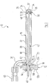
- a total of 10 designates a nozzle assembly, by means of which a corrosion protection wax can be applied in cavities of vehicle bodies.
- the nozzle assembly 10 comprises a bearing block 12 with two opposite and mutually parallel outer surfaces 12a, 12b. Perpendicular to these runs a stepped through hole 14 through the bearing block 12 therethrough.
- the through-bore 14 Starting from the outer surface 12a in the direction of the outer surface 12b, the through-bore 14 comprises three sections 14a, 14b, 14c, each having a circular cross-section, but different diameters.
- the section 14a hereby has the largest diameter
- the middle section 14b has the smallest diameter
- the section 14c has an intermediate diameter.
- the nozzle assembly 10 further comprises a cylindrical nozzle lance 16. This has at a fastening end 18 open in the axial direction on a circumferentially circumferential mounting flange 20.
- the mounting flange 20 is inserted into the portion 14 a of the through hole 14 in the bearing block 12, which has a diameter complementary to the mounting flange 20 and a matching depth.
- the nozzle lance 16 is releasably secured by screws 21 to the bearing block 12.
- the nozzle lance 16 is arranged in total coaxial with the through hole 14 in the bearing block 12.
- the nozzle lance 16 includes a body portion 22 extending from the mounting flange 20 at the mounting end 18 up to a head portion 24 extends at the distal end of the attachment end 18 of the discharge nozzle 26 of the nozzle lance 16.
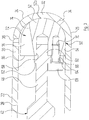
- the body portion 22 of the nozzle lance 16 is formed by a circular cylindrical housing wall 28. This is followed at the discharge end 26 of the nozzle lance 16, a likewise circular cylindrical wall portion 30 of the head portion 24, which in turn merges into a hemispherical end wall 32 of the head portion 24. Overall, the nozzle lance 16 is integrally formed. Alternatively, however, the head portion 24 may be detachably connected to the body portion 22 of the nozzle lance 16, for example by a threaded connection.
- the end wall 32 of the head portion 24 of the nozzle lance 16 has in the present embodiment, two discharge openings 34 and 36 with a circular cross section.
- the two discharge openings 34 and 36 are thus provided in one and the same nozzle lance 16.
- the longitudinal axis of the first discharge opening 34 extends at an angle of 45 ° to the longitudinal axis of the nozzle lance 16, whereas the longitudinal axis of the second discharge opening 36 is at 90 ° to the longitudinal axis of the nozzle lance 16.
- a supply line 38 penetrates the housing wall 28, which has a connection 40 at its end remote from the nozzle lance 16.
- the supply line 38 can be connected to a material source not shown here in the form of a mixing chamber, in which in a known manner, a compressed air / wax mixture can be generated, which then via the supply line 38 into the interior of the nozzle lance 16 is promoted.
- the nozzle assembly 10 includes a rotary shaft 42 with a circular Cross-section, which extends through the through hole 14 in the bearing block 12 and inside the nozzle lance 16.
- the rotary shaft 42 is rotatably mounted in the bearing block 12 by means of a pivot bearing 44, which is arranged in the portion 14 c of the through hole 14.
- a drive end 46 of the rotary shaft 42 is accessible from the outside on the side of the outer surface 12b of the bearing block 12 and can be connected there to a drive / gear unit not specifically shown here.
- the rotary shaft 42 tapers at its end opposite the drive end 46 to a coupling end 48, on which it carries a guide body 50.
- the guide body 50 is in FIG. 3 to see in detail and has a hemispherical end portion 52 with a hemispherical end face 52 a, which is complementary to the inner surface of the hemispherical end wall 32 of the head portion 24.
- the guide body 50 is arranged in the head section 24 of the nozzle lance 16 such that its end section 52 bears against the inner surface of the hemispherical end wall 32 of the head section 24.
- the hemispherical end portion 52 of the guide body 50 merges into a cylindrical portion 54, the clear outer contour is complementary to the inner circumferential surface of the circular cylindrical wall portion 30 of the head portion 24 and which ends in a base 56 perpendicular to its longitudinal axis.
- a receptacle 58 is incorporated, which is complementary to the free tip 60 at the coupling end 48 of the rotary shaft 42, which projects into the recess 58 in.
- a circumferential collar 62 is also provided, on which the guide body 50 rests and which the penetration depth of the free tip 60th the rotation shaft 42 is limited in the recess 58 of the guide body 50.
- the collar 62 is not rotationally symmetrical to the longitudinal axis of the rotary shaft 42 and includes a support portion 64 (see also FIG. 5 through which a threaded screw 68 is guided, which engages in a complementary threaded bore 70 in the guide body 50, whereby it is coupled to the rotary shaft 42.
- a support portion 64 see also FIG. 5 through which a threaded screw 68 is guided, which engages in a complementary threaded bore 70 in the guide body 50, whereby it is coupled to the rotary shaft 42.
- a flow groove 72 whose curved groove bottom 74 extends in the direction of the hemispherical outer surface 52a of the guide body 50 to obliquely radially outward.
- the groove walls 76 and 78 are opposite to a median plane of the flow groove 72, which in FIG. 5 is indicated as a dashed line, inclined in the direction radially outward.
- the flow groove 72 defines a flow passage through the guide body 50.
- annular space 80 Between the inner circumferential surface of the body portion 22 of the nozzle lance 16 and the rotary shaft 42 remains a feed space in the form of an annular space 80, which communicates with the supply line 38 and which can be fed with a compressed air / wax mixture.
- the central portion 14c of the through hole 14 in the bearing block 12 is sealed fluid-tight against this annular space 80 by means of a seal 82.
- the nozzle assembly 10 described above now works as follows: For use, the nozzle assembly 10 is attached to an application robot attached, as he is known in and of itself. As a rule, six-axis application robots are used.
- the port 40 of the supply line 38 is connected to the mentioned mixing chamber, in which a compressed air / wax mixture can be generated.
- the drive end 46 of the rotary shaft 42 is connected to the motor / gear unit, so that the rotary shaft 42 can be rotated in both rotational directions about its longitudinal axis. Due to the degrees of freedom of movement of the application robot, the nozzle assembly 10 can also be rotated as a whole about its longitudinal axis.
- the nozzle lance 16 is now introduced into the cavity of a vehicle body, in which a corrosion protection wax is to be introduced.
- the compressed air / wax mixture can be delivered with a main direction which corresponds to the direction of the longitudinal axis of the respective discharge opening 34 and 36.
- a dispensing cone will form around the respective longitudinal axis.
- the rotary shaft 42 is rotated by means of the motor / gear unit as long as the flow groove 72 in the guide body 50 a Assumes the position in which the second discharge opening 36 communicates via the flow groove 72 with the annular space 80 in the nozzle lance 16.
- the corresponding position of the rotary shaft 42 and the guide body 50 is in the Figures 2 and 3 to recognize.
- the compressed air / wax mixture is generated in the mixing chamber, which via the supply line 40 into the annular space 80th the nozzle lance 16 and flows into the flow groove 72 in the guide body 50 and is discharged from there through the second discharge opening 36 of the head portion 24 of the nozzle lance 16 to the outside.
- the rotary shaft 42 will continue to rotate by means of the motor / gear unit rotated until the flow groove 72 in the guide body 50 assumes a position in which the first discharge port 34 communicates via the flow groove 72 with the annular space 80 in the nozzle lance 16.
- the corresponding position of the rotary shaft 42 and the guide body 50 is in the FIGS. 4 and 5 shown.
- the flow path of the compressed air / wax mixture and thus of the actual coating material in the form of the wax from the mixing chamber can thus be set such that it leads optionally to the first discharge opening 34 or to the second discharge opening 36.
- the compressed air / wax mixture is circumferentially distributed around the nozzle lance 16 in the respective cavity.
- an optionally required change in the dispensing direction for the compressed air / wax mixture with respect to the cavity in the vehicle body can be achieved by changing the position of the nozzle lance 16 by controlling the robot arm accordingly.
- two discharge openings 34 and 36 are provided, which are arranged in a predefined and unchanging relative position to each other.
- even more such discharge openings may be provided in one and the same nozzle lance 16, which can communicate with its flow groove 72, depending on the position of the guide body 50.
- the longitudinal axes of the discharge openings may include angles other than 90 ° or 45 ° with the longitudinal axis of the nozzle lance 16, so that the main direction with which the compressed air / wax mixture is discharged via a certain discharge opening, can be changed.
- the nozzle lance 16 and in particular its head portion 24 can be tailored by a corresponding number of discharge openings and their arrangement with respect to several different cavities of a particular vehicle body to be treated.
- the nozzle lance 16 can thus be used for the application of different cavities of a vehicle body, which differ in their geometry. An exchange of an application nozzle, as it was previously required, when after a first cavity of a different cavity should be provided with wax, can thus be omitted.
- the baffle 50 includes not only the one flow groove 72, but also at least one further flow groove.
- two flow grooves in the guide body 50 can be achieved, for example, that the compressed air / wax mixture depending on the position of the guide body 50 can be dispensed simultaneously via the discharge openings 34 and 36 of the nozzle lance 16, but optionally only on the first discharge opening 34 or only via the second discharge opening 36.
- one or more passages may also be provided in the guide body 50, starting from its base 56 and extending so as to open into an associated discharge opening of the nozzle lance 16, depending on the position of the guide body 50.
- delivery openings with different cross-sections may also be provided instead of the delivery openings 34 and 36 which are circular in cross-section.
- the nozzle lance 16 may have any number of discharge openings, the cross section may also be formed arbitrarily.
- different geometries can be combined with each other to form a cross section, such as e.g. a cross section in the form of a keyhole, and dispensing openings may be arranged at different distances from each other. In this way, an individual adaptation to a vehicle body to be treated or to the cavities thereof can take place.
- the head portion 24 of the nozzle lance 16 is substantially hemispherical.
- the head portion of the nozzle lance 16 may be, for example, conical or frusto-conical.
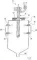
- the container 84 is also provided with spray nozzles 86, which are connected via lines 88 to a source of detergent not shown here and by means of which cleaning agent can be applied to the nozzle lance 16.
- the container 84 comprises a lamella cover 90 with lamellae 92 in the manner of an iris diaphragm, of which in the FIGS. 6 to 8 only one is provided with a reference numeral.
- the Lammellenabdeckung 90 is controlled by a pneumatic cylinder 94 (see. FIGS. 7 and 8 ).
- the nozzle lance 16 For cleaning the nozzle lance 16, this is pushed by a remaining between the retracted lamella immersion opening 96, wherein the fins 92 are retracted so far that they do not come into contact with the nozzle lance 16 (see. FIG. 7 ). Then, the fins 92 are moved to a stripping position on the nozzle lance 16 until they touch them and between the fins 92 a stripping 98 remains (see. FIG. 8 ). Thereafter, the nozzle lance 16 is moved back again, the lamellae 92 on the outer surface of the nozzle lance 16 adhering wax mechanically strip.
- the container 84 has in its bottom a drain opening 100, can run through the detergent and wax residues. If detergent is to be present up to a certain level in the container 84, the drain opening 100 is closed, for example by means of a plug.
- the cleaning can be done at the application site, without the nozzle lance 16 must be replaced. This is made possible in particular by the overall slim and space-saving design of the nozzle assembly 10.
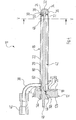
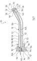
- FIG. 9 is shown as a further embodiment, a nozzle assembly 110.
- the nozzle lance 116 of the nozzle assembly 110 has a curvature.
- the nozzle lance can optionally be better adapted to a cavity of a vehicle body to be treated.
- the nozzle lance 116 is assembled from three individual parts 116a, 116b and 116c, the part 116c forming the head section 124 of the nozzle lance 116.
- the parts 116a, 116b and 116c may be welded together.
- the mounting flange 120 of the nozzle lance 116 is thicker than the mounting flange 20 of the nozzle lance 16 and projects only partially in the portion 114 a of the through hole 114 in the bearing block 112.
- the body portion 122 of the nozzle lance 116 From the body portion 122 of the nozzle lance 116 no supply line goes off. Rather, the body portion 122 of the nozzle lance 116 has the externally accessible port 140 for connection to the mixing chamber not specifically shown.
- the rotary shaft 142 includes three interconnected portions 142a, 142b and 142c.
- the section 142a forms the Drive end 146 of the rotary shaft 142, which projects through the bearing block 112 through to the outside.
- the central portion 142b of the rotary shaft 142 which runs inside the curved nozzle lance 116, is flexible and has a diameter which corresponds approximately to the diameter of the coupling end 48 of the rotary shaft 42. Thereby, the central portion 142b of the rotary shaft 142 can follow the curvature of the nozzle lance 116 without contacting the inner circumferential surface thereof.
- the third section 142c of the rotary shaft 142 forms the coupling end 148 thereof.
- nozzle arrangement 10 is correspondingly corresponding to nozzle arrangement 110. This also applies to the related to the FIGS. 6 to 8 explained cleaning process.
Landscapes
- Nozzles (AREA)
- Coating Apparatus (AREA)
Applications Claiming Priority (2)
| Application Number | Priority Date | Filing Date | Title |
|---|---|---|---|
| DE102009048899A DE102009048899A1 (de) | 2009-10-09 | 2009-10-09 | Düsenanordnung |
| PCT/EP2010/005921 WO2011042129A1 (de) | 2009-10-09 | 2010-09-29 | Düsenanordnung |
Publications (2)
| Publication Number | Publication Date |
|---|---|
| EP2485848A1 EP2485848A1 (de) | 2012-08-15 |
| EP2485848B1 true EP2485848B1 (de) | 2018-05-16 |
Family
ID=43259759
Family Applications (1)
| Application Number | Title | Priority Date | Filing Date |
|---|---|---|---|
| EP10762872.9A Not-in-force EP2485848B1 (de) | 2009-10-09 | 2010-09-29 | Düsenanordnung |
Country Status (6)
| Country | Link |
|---|---|
| US (1) | US9067224B2 (enExample) |
| EP (1) | EP2485848B1 (enExample) |
| CN (1) | CN102548664B (enExample) |
| DE (1) | DE102009048899A1 (enExample) |
| IN (1) | IN2012DN02989A (enExample) |
| WO (1) | WO2011042129A1 (enExample) |
Families Citing this family (7)
| Publication number | Priority date | Publication date | Assignee | Title |
|---|---|---|---|---|
| DE102012111955A1 (de) * | 2012-12-07 | 2014-06-12 | Euro - Automation SA | Steuervorrichtung und Anlage für die Konservierung metallischer Bauteile |
| CN104441657B (zh) * | 2014-11-12 | 2016-08-17 | 广东工业大学 | 一种可控口径的3d打印机喷头及其控制方法 |
| DE102016005064A1 (de) | 2016-04-28 | 2016-09-29 | Daimler Ag | Vorrichtung zum Applizieren eines Oberflächenschutzmittels auf eine außenliegende Oberfläche einer Fahrzeugkarosserie |
| DE102016125220A1 (de) * | 2016-12-21 | 2018-06-21 | Polyplan Gmbh Polyurethan-Maschinen | Vorrichtung und Verfahren zum Aufbringen von flüssigen oder pastösen Stoffen |
| FR3063025B1 (fr) * | 2017-02-17 | 2021-09-24 | Metalizz | Dispositif de traitement de la surface d'au moins un objet par une solution specifique |
| CN109777216B (zh) * | 2018-12-10 | 2021-05-04 | 北京汽车集团有限公司 | 喷头、约束阻尼涂层结构及其制备方法 |
| CN110385219B (zh) * | 2019-07-04 | 2020-12-01 | 江苏长虹机械设计院有限公司 | 一种方便喷头残留涂料进行清理的汽车涂装设备 |
Family Cites Families (21)
| Publication number | Priority date | Publication date | Assignee | Title |
|---|---|---|---|---|
| US1612326A (en) * | 1926-02-24 | 1926-12-28 | Frank Sutcliffe | Garden-hose attachment |
| US2647014A (en) * | 1952-07-25 | 1953-07-28 | Raleigh M Edwards | Sprinkler head |
| US3044441A (en) * | 1960-05-06 | 1962-07-17 | American Can Co | Spray coating apparatus |
| FR1280937A (fr) * | 1961-02-01 | 1962-01-08 | Antilowa | Dispositif de division d'un agent à pulvériser et de renforcement pour pistolets de pulvérisation |
| US3227375A (en) * | 1963-02-18 | 1966-01-04 | Ziebart Kurt | Rustproofing of the bodies of automotive vehicles |
| US3377028A (en) * | 1966-04-05 | 1968-04-09 | L & A Products Inc | Self-sealing connector for multiaperture nozzle |
| US3697313A (en) * | 1970-02-24 | 1972-10-10 | Nordson Corp | Method of spraying closed end cans |
| DE2263266A1 (de) * | 1972-12-23 | 1974-07-11 | Daimler Benz Ag | Duesenkopf zum auftragen von ueberzugsstoffen |
| DE2526702A1 (de) | 1975-06-14 | 1976-12-23 | Volkswagenwerk Ag | Spruehduese, insbesondere zur hohlraumkonservierung |
| US4272567A (en) * | 1978-11-17 | 1981-06-09 | American Can Company | Controlled dispersion of coating inside non-circular hollow articles |
| DE3230247A1 (de) * | 1982-08-13 | 1984-02-16 | J. Wagner Gmbh, 7990 Friedrichshafen | Verstellduesenanordnung |
| SE463772B (sv) * | 1989-05-30 | 1991-01-21 | Kent Strid | Dysa foer spritsroer |
| SE503696C2 (sv) | 1995-07-12 | 1996-08-05 | Volvo Ab | Sprutverktyg omställbart i olika riktningar och med minst två munstycken |
| US6085995A (en) * | 1998-06-24 | 2000-07-11 | Kah, Jr.; Carl L. C. | Selectable nozzle rotary driven sprinkler |
| US6554212B2 (en) | 2001-02-08 | 2003-04-29 | Ipr Automation Lp | Robot spray head for cavity treatment |
| DE10257783B3 (de) | 2002-12-11 | 2004-03-18 | Alfred Kärcher Gmbh & Co. Kg | Düsenanordnung für ein Hochdruckreinigungsgerät |
| DE10320856B3 (de) * | 2003-05-09 | 2004-09-23 | INT GmbH Ingenieurbüro für Neue Technologien, Anlagenbau, Verfahrenstechnik, ADFOSY | Mehrfach-Düsenkopf |
| DE102004046351A1 (de) * | 2004-09-24 | 2006-03-30 | Daimlerchrysler Ag | Verfahren zur automatischen Konservierung der Hohlräume eines Kraftfahrzeugs |
| US20080022450A1 (en) * | 2005-03-14 | 2008-01-31 | Tsai Pi K | Holder device for shower head and nozzle |
| US20090065607A1 (en) * | 2007-09-10 | 2009-03-12 | Gardner Michael R | Pressure washer system |
| US8545937B2 (en) * | 2009-08-31 | 2013-10-01 | Nordson Corporation | Spray coating with uniform flow distribution |
-
2009
- 2009-10-09 DE DE102009048899A patent/DE102009048899A1/de not_active Withdrawn
-
2010
- 2010-09-29 WO PCT/EP2010/005921 patent/WO2011042129A1/de not_active Ceased
- 2010-09-29 US US13/500,354 patent/US9067224B2/en not_active Expired - Fee Related
- 2010-09-29 EP EP10762872.9A patent/EP2485848B1/de not_active Not-in-force
- 2010-09-29 IN IN2989DEN2012 patent/IN2012DN02989A/en unknown
- 2010-09-29 CN CN201080045406.1A patent/CN102548664B/zh not_active Expired - Fee Related
Non-Patent Citations (1)
| Title |
|---|
| None * |
Also Published As
| Publication number | Publication date |
|---|---|
| CN102548664A (zh) | 2012-07-04 |
| US20120234234A1 (en) | 2012-09-20 |
| IN2012DN02989A (enExample) | 2015-07-31 |
| CN102548664B (zh) | 2017-02-08 |
| WO2011042129A1 (de) | 2011-04-14 |
| EP2485848A1 (de) | 2012-08-15 |
| DE102009048899A1 (de) | 2011-04-14 |
| US9067224B2 (en) | 2015-06-30 |
Similar Documents
| Publication | Publication Date | Title |
|---|---|---|
| EP2485848B1 (de) | Düsenanordnung | |
| EP2605859B1 (de) | Düse zur applikation eines auftragsmittels | |
| EP1931953A1 (de) | Dosiereinrichtung für pulver- oder pastenförmige substanzen | |
| EP3181245B1 (de) | Düsenanordnung für fliessfähige substanzen | |
| DE102012216206B4 (de) | Vorrichtung und Verfahren zum Reinigen eines Bearbeitungsraumes einer Teigbearbeitungsstation | |
| EP3536409A1 (de) | Vorrichtung zum reinigen, sprühen, spülen, auftragen oder trocknen im innenraum von behältern und rohr- und anlagensystemen | |
| DE102009001396A1 (de) | Sprühvorrichtung | |
| DE2711596A1 (de) | Verfahren zur aufbringung eines rostschutzmittels | |
| DE202007014659U1 (de) | Reinigungsvorrichtung, Werkzeugkopf und Reinigungsbürste hierfür | |
| DE102013212885A1 (de) | Reinigungsvorrichtung | |
| DE102005038193B4 (de) | Behälterreinigungsvorrichtung | |
| EP2178487B1 (de) | Kapselfüllmaschine mit reinigungsvorrichtung | |
| EP2885088B1 (de) | Austragvorrichtung | |
| EP3976269B1 (de) | Reinigungsvorrichtung und verfahren zur montage einer reinigungsvorrichtung | |
| EP2138243B1 (de) | Zielstrahlreiniger | |
| EP3469909B1 (de) | Kontinuierlich arbeitende teigknetvorrichtung | |
| EP1997568B1 (de) | Behandlungsvorrichtung zum Reinigen und/oder zum Trocknen von Werkstücken | |
| EP3714991A1 (de) | Sprühvorrichtung zum versprühen von fluiden | |
| EP1754531A1 (de) | Vorrichtung zum Mischen und Aufbringen eines aus mindestens zwei Komponenten bestehenden pastösen Materials auf ein Substrat | |
| DE10321425B4 (de) | Kanalreinigungsgerät | |
| DE202005004711U1 (de) | Vorrichtung zur Innenreinigung von Behältern | |
| EP4452509A1 (de) | Reiniger | |
| EP3670001B1 (de) | Verfahren zur hohlraumkonservierung, mischdüseneinheit und hohlraumkonservierungseinrichtung mit einer solchen mischdüseneinheit | |
| EP1452235B1 (de) | Glockenteller und Rotationszerstäuber | |
| DE3930879A1 (de) | Allseits verschliessbare reinigungskammer zum reinigen, insbesondere entfetten, verschmutzter teile durch bespritzen mit einer fluessigkeit |
Legal Events
| Date | Code | Title | Description |
|---|---|---|---|
| PUAI | Public reference made under article 153(3) epc to a published international application that has entered the european phase |
Free format text: ORIGINAL CODE: 0009012 |
|
| 17P | Request for examination filed |
Effective date: 20120320 |
|
| AK | Designated contracting states |
Kind code of ref document: A1 Designated state(s): AL AT BE BG CH CY CZ DE DK EE ES FI FR GB GR HR HU IE IS IT LI LT LU LV MC MK MT NL NO PL PT RO SE SI SK SM TR |
|
| DAX | Request for extension of the european patent (deleted) | ||
| RAP1 | Party data changed (applicant data changed or rights of an application transferred) |
Owner name: EISENMANN SE |
|
| STAA | Information on the status of an ep patent application or granted ep patent |
Free format text: STATUS: EXAMINATION IS IN PROGRESS |
|
| 17Q | First examination report despatched |
Effective date: 20170102 |
|
| RIC1 | Information provided on ipc code assigned before grant |
Ipc: B05B 1/16 20060101AFI20171026BHEP Ipc: B05B 7/26 20060101ALN20171026BHEP Ipc: B05B 13/06 20060101ALI20171026BHEP Ipc: B05B 15/02 20060101ALI20171026BHEP Ipc: B05B 13/04 20060101ALN20171026BHEP |
|
| GRAP | Despatch of communication of intention to grant a patent |
Free format text: ORIGINAL CODE: EPIDOSNIGR1 |
|
| STAA | Information on the status of an ep patent application or granted ep patent |
Free format text: STATUS: GRANT OF PATENT IS INTENDED |
|
| INTG | Intention to grant announced |
Effective date: 20171204 |
|
| GRAS | Grant fee paid |
Free format text: ORIGINAL CODE: EPIDOSNIGR3 |
|
| GRAA | (expected) grant |
Free format text: ORIGINAL CODE: 0009210 |
|
| STAA | Information on the status of an ep patent application or granted ep patent |
Free format text: STATUS: THE PATENT HAS BEEN GRANTED |
|
| AK | Designated contracting states |
Kind code of ref document: B1 Designated state(s): AL AT BE BG CH CY CZ DE DK EE ES FI FR GB GR HR HU IE IS IT LI LT LU LV MC MK MT NL NO PL PT RO SE SI SK SM TR |
|
| REG | Reference to a national code |
Ref country code: GB Ref legal event code: FG4D Free format text: NOT ENGLISH |
|
| REG | Reference to a national code |
Ref country code: CH Ref legal event code: EP |
|
| REG | Reference to a national code |
Ref country code: IE Ref legal event code: FG4D Free format text: LANGUAGE OF EP DOCUMENT: GERMAN |
|
| REG | Reference to a national code |
Ref country code: DE Ref legal event code: R096 Ref document number: 502010014980 Country of ref document: DE |
|
| REG | Reference to a national code |
Ref country code: AT Ref legal event code: REF Ref document number: 999044 Country of ref document: AT Kind code of ref document: T Effective date: 20180615 |
|
| REG | Reference to a national code |
Ref country code: NL Ref legal event code: MP Effective date: 20180516 |
|
| REG | Reference to a national code |
Ref country code: LT Ref legal event code: MG4D |
|
| REG | Reference to a national code |
Ref country code: FR Ref legal event code: PLFP Year of fee payment: 9 |
|
| PG25 | Lapsed in a contracting state [announced via postgrant information from national office to epo] |
Ref country code: SE Free format text: LAPSE BECAUSE OF FAILURE TO SUBMIT A TRANSLATION OF THE DESCRIPTION OR TO PAY THE FEE WITHIN THE PRESCRIBED TIME-LIMIT Effective date: 20180516 Ref country code: FI Free format text: LAPSE BECAUSE OF FAILURE TO SUBMIT A TRANSLATION OF THE DESCRIPTION OR TO PAY THE FEE WITHIN THE PRESCRIBED TIME-LIMIT Effective date: 20180516 Ref country code: BG Free format text: LAPSE BECAUSE OF FAILURE TO SUBMIT A TRANSLATION OF THE DESCRIPTION OR TO PAY THE FEE WITHIN THE PRESCRIBED TIME-LIMIT Effective date: 20180816 Ref country code: NO Free format text: LAPSE BECAUSE OF FAILURE TO SUBMIT A TRANSLATION OF THE DESCRIPTION OR TO PAY THE FEE WITHIN THE PRESCRIBED TIME-LIMIT Effective date: 20180816 Ref country code: ES Free format text: LAPSE BECAUSE OF FAILURE TO SUBMIT A TRANSLATION OF THE DESCRIPTION OR TO PAY THE FEE WITHIN THE PRESCRIBED TIME-LIMIT Effective date: 20180516 Ref country code: LT Free format text: LAPSE BECAUSE OF FAILURE TO SUBMIT A TRANSLATION OF THE DESCRIPTION OR TO PAY THE FEE WITHIN THE PRESCRIBED TIME-LIMIT Effective date: 20180516 |
|
| PG25 | Lapsed in a contracting state [announced via postgrant information from national office to epo] |
Ref country code: GR Free format text: LAPSE BECAUSE OF FAILURE TO SUBMIT A TRANSLATION OF THE DESCRIPTION OR TO PAY THE FEE WITHIN THE PRESCRIBED TIME-LIMIT Effective date: 20180817 Ref country code: NL Free format text: LAPSE BECAUSE OF FAILURE TO SUBMIT A TRANSLATION OF THE DESCRIPTION OR TO PAY THE FEE WITHIN THE PRESCRIBED TIME-LIMIT Effective date: 20180516 Ref country code: HR Free format text: LAPSE BECAUSE OF FAILURE TO SUBMIT A TRANSLATION OF THE DESCRIPTION OR TO PAY THE FEE WITHIN THE PRESCRIBED TIME-LIMIT Effective date: 20180516 Ref country code: LV Free format text: LAPSE BECAUSE OF FAILURE TO SUBMIT A TRANSLATION OF THE DESCRIPTION OR TO PAY THE FEE WITHIN THE PRESCRIBED TIME-LIMIT Effective date: 20180516 |
|
| PG25 | Lapsed in a contracting state [announced via postgrant information from national office to epo] |
Ref country code: CZ Free format text: LAPSE BECAUSE OF FAILURE TO SUBMIT A TRANSLATION OF THE DESCRIPTION OR TO PAY THE FEE WITHIN THE PRESCRIBED TIME-LIMIT Effective date: 20180516 Ref country code: RO Free format text: LAPSE BECAUSE OF FAILURE TO SUBMIT A TRANSLATION OF THE DESCRIPTION OR TO PAY THE FEE WITHIN THE PRESCRIBED TIME-LIMIT Effective date: 20180516 Ref country code: EE Free format text: LAPSE BECAUSE OF FAILURE TO SUBMIT A TRANSLATION OF THE DESCRIPTION OR TO PAY THE FEE WITHIN THE PRESCRIBED TIME-LIMIT Effective date: 20180516 Ref country code: PL Free format text: LAPSE BECAUSE OF FAILURE TO SUBMIT A TRANSLATION OF THE DESCRIPTION OR TO PAY THE FEE WITHIN THE PRESCRIBED TIME-LIMIT Effective date: 20180516 Ref country code: DK Free format text: LAPSE BECAUSE OF FAILURE TO SUBMIT A TRANSLATION OF THE DESCRIPTION OR TO PAY THE FEE WITHIN THE PRESCRIBED TIME-LIMIT Effective date: 20180516 Ref country code: SK Free format text: LAPSE BECAUSE OF FAILURE TO SUBMIT A TRANSLATION OF THE DESCRIPTION OR TO PAY THE FEE WITHIN THE PRESCRIBED TIME-LIMIT Effective date: 20180516 |
|
| REG | Reference to a national code |
Ref country code: CH Ref legal event code: PK Free format text: BERICHTIGUNGEN |
|
| RIC2 | Information provided on ipc code assigned after grant |
Ipc: B05B 15/02 20060101ALI20171026BHEP Ipc: B05B 1/16 20060101AFI20171026BHEP Ipc: B05B 7/26 20060101ALN20171026BHEP Ipc: B05B 13/06 20060101ALI20171026BHEP Ipc: B05B 13/04 20060101ALN20171026BHEP |
|
| REG | Reference to a national code |
Ref country code: DE Ref legal event code: R097 Ref document number: 502010014980 Country of ref document: DE |
|
| PG25 | Lapsed in a contracting state [announced via postgrant information from national office to epo] |
Ref country code: SM Free format text: LAPSE BECAUSE OF FAILURE TO SUBMIT A TRANSLATION OF THE DESCRIPTION OR TO PAY THE FEE WITHIN THE PRESCRIBED TIME-LIMIT Effective date: 20180516 |
|
| PLBE | No opposition filed within time limit |
Free format text: ORIGINAL CODE: 0009261 |
|
| STAA | Information on the status of an ep patent application or granted ep patent |
Free format text: STATUS: NO OPPOSITION FILED WITHIN TIME LIMIT |
|
| 26N | No opposition filed |
Effective date: 20190219 |
|
| PG25 | Lapsed in a contracting state [announced via postgrant information from national office to epo] |
Ref country code: MC Free format text: LAPSE BECAUSE OF FAILURE TO SUBMIT A TRANSLATION OF THE DESCRIPTION OR TO PAY THE FEE WITHIN THE PRESCRIBED TIME-LIMIT Effective date: 20180516 |
|
| REG | Reference to a national code |
Ref country code: CH Ref legal event code: PL |
|
| GBPC | Gb: european patent ceased through non-payment of renewal fee |
Effective date: 20180929 |
|
| PG25 | Lapsed in a contracting state [announced via postgrant information from national office to epo] |
Ref country code: SI Free format text: LAPSE BECAUSE OF FAILURE TO SUBMIT A TRANSLATION OF THE DESCRIPTION OR TO PAY THE FEE WITHIN THE PRESCRIBED TIME-LIMIT Effective date: 20180516 |
|
| REG | Reference to a national code |
Ref country code: BE Ref legal event code: MM Effective date: 20180930 |
|
| REG | Reference to a national code |
Ref country code: IE Ref legal event code: MM4A |
|
| PG25 | Lapsed in a contracting state [announced via postgrant information from national office to epo] |
Ref country code: LU Free format text: LAPSE BECAUSE OF NON-PAYMENT OF DUE FEES Effective date: 20180929 |
|
| PG25 | Lapsed in a contracting state [announced via postgrant information from national office to epo] |
Ref country code: IE Free format text: LAPSE BECAUSE OF NON-PAYMENT OF DUE FEES Effective date: 20180929 |
|
| PG25 | Lapsed in a contracting state [announced via postgrant information from national office to epo] |
Ref country code: BE Free format text: LAPSE BECAUSE OF NON-PAYMENT OF DUE FEES Effective date: 20180930 Ref country code: LI Free format text: LAPSE BECAUSE OF NON-PAYMENT OF DUE FEES Effective date: 20180930 Ref country code: CH Free format text: LAPSE BECAUSE OF NON-PAYMENT OF DUE FEES Effective date: 20180930 |
|
| PG25 | Lapsed in a contracting state [announced via postgrant information from national office to epo] |
Ref country code: GB Free format text: LAPSE BECAUSE OF NON-PAYMENT OF DUE FEES Effective date: 20180929 |
|
| REG | Reference to a national code |
Ref country code: AT Ref legal event code: MM01 Ref document number: 999044 Country of ref document: AT Kind code of ref document: T Effective date: 20180929 |
|
| PG25 | Lapsed in a contracting state [announced via postgrant information from national office to epo] |
Ref country code: AL Free format text: LAPSE BECAUSE OF FAILURE TO SUBMIT A TRANSLATION OF THE DESCRIPTION OR TO PAY THE FEE WITHIN THE PRESCRIBED TIME-LIMIT Effective date: 20180516 |
|
| PG25 | Lapsed in a contracting state [announced via postgrant information from national office to epo] |
Ref country code: AT Free format text: LAPSE BECAUSE OF NON-PAYMENT OF DUE FEES Effective date: 20180929 Ref country code: MT Free format text: LAPSE BECAUSE OF FAILURE TO SUBMIT A TRANSLATION OF THE DESCRIPTION OR TO PAY THE FEE WITHIN THE PRESCRIBED TIME-LIMIT Effective date: 20180516 |
|
| PG25 | Lapsed in a contracting state [announced via postgrant information from national office to epo] |
Ref country code: TR Free format text: LAPSE BECAUSE OF FAILURE TO SUBMIT A TRANSLATION OF THE DESCRIPTION OR TO PAY THE FEE WITHIN THE PRESCRIBED TIME-LIMIT Effective date: 20180516 |
|
| PG25 | Lapsed in a contracting state [announced via postgrant information from national office to epo] |
Ref country code: PT Free format text: LAPSE BECAUSE OF FAILURE TO SUBMIT A TRANSLATION OF THE DESCRIPTION OR TO PAY THE FEE WITHIN THE PRESCRIBED TIME-LIMIT Effective date: 20180516 Ref country code: HU Free format text: LAPSE BECAUSE OF FAILURE TO SUBMIT A TRANSLATION OF THE DESCRIPTION OR TO PAY THE FEE WITHIN THE PRESCRIBED TIME-LIMIT; INVALID AB INITIO Effective date: 20100929 |
|
| PG25 | Lapsed in a contracting state [announced via postgrant information from national office to epo] |
Ref country code: CY Free format text: LAPSE BECAUSE OF FAILURE TO SUBMIT A TRANSLATION OF THE DESCRIPTION OR TO PAY THE FEE WITHIN THE PRESCRIBED TIME-LIMIT Effective date: 20180516 Ref country code: MK Free format text: LAPSE BECAUSE OF NON-PAYMENT OF DUE FEES Effective date: 20180516 |
|
| PG25 | Lapsed in a contracting state [announced via postgrant information from national office to epo] |
Ref country code: IS Free format text: LAPSE BECAUSE OF FAILURE TO SUBMIT A TRANSLATION OF THE DESCRIPTION OR TO PAY THE FEE WITHIN THE PRESCRIBED TIME-LIMIT Effective date: 20180916 |
|
| PGFP | Annual fee paid to national office [announced via postgrant information from national office to epo] |
Ref country code: DE Payment date: 20200925 Year of fee payment: 11 Ref country code: FR Payment date: 20200914 Year of fee payment: 11 |
|
| PGFP | Annual fee paid to national office [announced via postgrant information from national office to epo] |
Ref country code: IT Payment date: 20200922 Year of fee payment: 11 |
|
| REG | Reference to a national code |
Ref country code: DE Ref legal event code: R119 Ref document number: 502010014980 Country of ref document: DE |
|
| PG25 | Lapsed in a contracting state [announced via postgrant information from national office to epo] |
Ref country code: FR Free format text: LAPSE BECAUSE OF NON-PAYMENT OF DUE FEES Effective date: 20210930 Ref country code: DE Free format text: LAPSE BECAUSE OF NON-PAYMENT OF DUE FEES Effective date: 20220401 |
|
| PG25 | Lapsed in a contracting state [announced via postgrant information from national office to epo] |
Ref country code: IT Free format text: LAPSE BECAUSE OF NON-PAYMENT OF DUE FEES Effective date: 20210929 |