EP2485405B1 - Direct current power line communication system and direct current power line communication apparatus - Google Patents
Direct current power line communication system and direct current power line communication apparatus Download PDFInfo
- Publication number
- EP2485405B1 EP2485405B1 EP10820157.5A EP10820157A EP2485405B1 EP 2485405 B1 EP2485405 B1 EP 2485405B1 EP 10820157 A EP10820157 A EP 10820157A EP 2485405 B1 EP2485405 B1 EP 2485405B1
- Authority
- EP
- European Patent Office
- Prior art keywords
- direct current
- voltage
- power line
- line communication
- signal
- Prior art date
- Legal status (The legal status is an assumption and is not a legal conclusion. Google has not performed a legal analysis and makes no representation as to the accuracy of the status listed.)
- Active
Links
- 238000004891 communication Methods 0.000 title claims description 347
- 230000005540 biological transmission Effects 0.000 claims description 130
- 238000001514 detection method Methods 0.000 claims description 21
- 238000006243 chemical reaction Methods 0.000 description 20
- 239000003990 capacitor Substances 0.000 description 19
- 238000000034 method Methods 0.000 description 10
- 230000006870 function Effects 0.000 description 8
- 238000009499 grossing Methods 0.000 description 8
- 230000004044 response Effects 0.000 description 6
- 238000010586 diagram Methods 0.000 description 3
- 108010001267 Protein Subunits Proteins 0.000 description 2
- 230000008859 change Effects 0.000 description 2
- 230000006641 stabilisation Effects 0.000 description 2
- 238000011105 stabilization Methods 0.000 description 2
- 238000012935 Averaging Methods 0.000 description 1
- 230000002238 attenuated effect Effects 0.000 description 1
- 230000008878 coupling Effects 0.000 description 1
- 238000010168 coupling process Methods 0.000 description 1
- 238000005859 coupling reaction Methods 0.000 description 1
- 230000000694 effects Effects 0.000 description 1
- 230000008569 process Effects 0.000 description 1
- 230000008054 signal transmission Effects 0.000 description 1
Images


Classifications
-
- H—ELECTRICITY
- H04—ELECTRIC COMMUNICATION TECHNIQUE
- H04B—TRANSMISSION
- H04B3/00—Line transmission systems
- H04B3/54—Systems for transmission via power distribution lines
- H04B3/548—Systems for transmission via power distribution lines the power on the line being DC
-
- H—ELECTRICITY
- H04—ELECTRIC COMMUNICATION TECHNIQUE
- H04B—TRANSMISSION
- H04B3/00—Line transmission systems
- H04B3/54—Systems for transmission via power distribution lines
- H04B3/542—Systems for transmission via power distribution lines the information being in digital form
-
- H—ELECTRICITY
- H04—ELECTRIC COMMUNICATION TECHNIQUE
- H04B—TRANSMISSION
- H04B2203/00—Indexing scheme relating to line transmission systems
- H04B2203/54—Aspects of powerline communications not already covered by H04B3/54 and its subgroups
- H04B2203/5429—Applications for powerline communications
- H04B2203/5437—Wired telephone
-
- H—ELECTRICITY
- H04—ELECTRIC COMMUNICATION TECHNIQUE
- H04B—TRANSMISSION
- H04B2203/00—Indexing scheme relating to line transmission systems
- H04B2203/54—Aspects of powerline communications not already covered by H04B3/54 and its subgroups
- H04B2203/5429—Applications for powerline communications
- H04B2203/5445—Local network
-
- H—ELECTRICITY
- H04—ELECTRIC COMMUNICATION TECHNIQUE
- H04B—TRANSMISSION
- H04B2203/00—Indexing scheme relating to line transmission systems
- H04B2203/54—Aspects of powerline communications not already covered by H04B3/54 and its subgroups
- H04B2203/5429—Applications for powerline communications
- H04B2203/545—Audio/video application, e.g. interphone
Definitions
- the present invention relates to a direct current power line communication system and direct current power line communication apparatus.
- alternating current power is first supplied from the power company to a pole-mounted transformer and is then stepped down by this pole-mounted transformer, after which the stepped-down alternating current power is supplied to the users (homes, factories, stores, and so forth).
- the aim is to improve power utilization efficiency by performing direct current drive of electronic devices such as television receivers, personal computers, telephones, and so forth, installed in individual user premises.
- JP 2007 312046 discloses a DC power line communication system enabling communication between power lines connected to DC power supplies having a plurality of DC voltages
- a direct current power line communication apparatus of the present invention transmits a signal using a direct current voltage line, and employs a configuration having: a transmission section that is connected to the direct current voltage line and transmits a signal to the direct current voltage line; a control section that is connected to the transmission section and controls the transmission section; and a voltage detection section that is connected to the control section and the direct current voltage line, detects a voltage of the direct current voltage line, and reports the detected voltage to the control section; wherein the control section transmits information including information on a value of the voltage to another direct current power line communication apparatus via the transmission section.
- a direct current power line communication apparatus of the present invention can report the voltage of a direct current voltage line to another direct current power line communication apparatus. That is to say, a direct current power line communication apparatus of the present invention can report information on the voltage which is supplied to the direct current power line communication apparatus, to another direct current power line communication apparatus. By this means, the other direct current power line communication apparatus can transmit a signal to the direct current power line communication apparatus using a signal size based on this drive voltage. Consequently, communication between direct current power line communication apparatus via a direct current voltage line can be stabilized.
- reference code 1 indicates a pole-mounted transformer that steps down an alternating current voltage supplied from a power company (not shown), and this pole-mounted transformer 1 and alternating current-direct current conversion section 3 in individual user premises (home, factory, store, or the like) 2 are connected by direct current voltage line 4.
- alternating current supplied to alternating current-direct current conversion section 3 from pole-mounted transformer 1 is branched internally, with one branch passing through alternating current-direct current conversion section 3 and being supplied to power outlet 6 from direct current voltage line 5.
- a currently commonly used alternating current drive type electronic device 7 is connected to this power outlet 6.
- the other current branched by alternating current-direct current conversion section 3 is converted to a 48 V direct current, for example, and is supplied to user-specific voltage changing apparatus 9 via direct current voltage line 8.
- Direct current generation section 10 such as a solar battery system and direct current storage section 11 such as a storage battery, for example, are connected between alternating current-direct current conversion section 3 and user-specific voltage changing apparatus 9 via respective diodes 12.
- User-specific voltage changing apparatus 9 is for generating DC (direct current) 6 V, DC 12 V, DC 48 V, and DC 300 V from a supplied DC 48 V, and has a configuration including direct current input terminal 9a, voltage changing circuit 9b connected to this direct current input terminal 9a, and plurality of direct current output terminals 9c, 9d, 9e, and 9f connected to this voltage changing circuit 9b, in which voltage changing circuit 9b changes a direct current voltage input from direct current input terminal 9a to a plurality of direct current voltages with different voltage values and outputs these to direct current output terminals 9c through 9f.
- user-specific voltage changing apparatus 9 is configured so that DC 6 V is output from direct current output terminal 9c, DC 12 V is output from direct current output terminal 9d, DC 48 V is output from direct current output terminal 9e, and DC 300 V is output from direct current output terminal 9f.
- Power outlet 13 is connected to direct current output terminal 9c, providing a configuration whereby DC 6 V is output from power outlet 13 via direct current voltage line 13a.
- power outlet 14 is connected to direct current output terminal 9d, providing a configuration whereby DC 12 V is output from power outlet 14 via direct current voltage line 14a.
- power outlet 15 is connected to direct current output terminal 9e, providing a configuration whereby DC 48 V is output from power outlet 15 via direct current voltage line 15a.
- power outlet 16 is connected to direct current output terminal 9f, providing a configuration whereby DC 300 V is output from power outlet 16 via direct current voltage line 16a.
- Personal computer 17 is connected to power outlet 13 as an example of an electronic device
- telephone 18 is connected to power outlet 14 as an example of an electronic device
- television receiver 19 and DVD recorder 20 are connected to power outlet 15 as examples of electronic devices
- air conditioner 21 is connected to power outlet 16 as an example of an electronic device, all these devices being connected in a freely removable fashion.
- Personal computer 17 is constructed to be driven at DC 6 V, telephone 18 at DC 12 V, television receiver 19 and DVD recorder 20 at DC 48 V, and air conditioner 21 at DC 300 V.
- voltage changing circuit 9b of user-specif voltage changing apparatus 9 is provided with many electronic parts including switching elements for performing voltage changing, and therefore in a state in which this voltage changing circuit 9b is bypassed, a state is established in which communication among personal computer 17, telephone 18, television receiver 19, DVD recorder 20, and air conditioner 21 can be performed.
- FIG.2A and FIG.2B represent personal computer 17, telephone 18, television receiver 19, DVD recorder 20, and air conditioner 21 used as direct current drive type electronic devices, and show voltage supply parts of television receiver 19.
- power supply section 25 driven at DC 48 V, and communication section 26 are provided as voltage supply parts of television receiver 19.
- communication section 26 has a configuration including direct current voltage line 15a, transmission section 27 and reception section 28 connected to this direct current voltage line 15a, PLC communication control section 29 connected to transmission section 27 and reception section 28, voltage detection section 30 connected to PLC communication control section 29 and direct current voltage line 15a, and transmission output control section 50 connected to PLC communication control section 29 and transmission section 27.
- drive voltage information for this television receiver 19, direct current 48 V
- transmission section 27 via direct current voltage line 15a to other direct current drive type electronic devices such as personal computer 17, telephone 18, television receiver 19, DVD recorder 20, and air conditioner 21.
- personal computer 17, telephone 18, television receiver 19, DVD recorder 20, and air conditioner 21 also have the same kind of configuration as shown in FIG.2A and FIG.2B , and these direct current drive type electronic devices such as personal computer 17, telephone 18, television receiver 19, DVD recorder 20, and air conditioner 21 are in a state in which communication can be performed as necessary via direct current voltage lines 13a through 16a and capacitors 22 through 24.
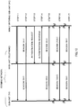
- FIG.3 is a drawing showing a signal, for which packet communication is performed, transmitted from one of personal computer 17, telephone 18, television receiver 19, DVD recorder 20, or air conditioner 21, to all the others.
- Initial information 32 in frame 31 shown in FIG.3 is information used for synchronization during transmission/reception and carrier detection, following information 33 is information that includes control information such as a transmission source address, and final information 34 is information that includes actual data (video information, audio information, and so forth).
- information 33 includes transmission destination PLC address information 35, transmission source PLC address information 36, and drive voltage information 37.
- information 34 includes transmission destination IP address information 38, transmission source IP address information 39, and actual data information 40.
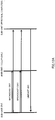
- FIG.4A and FIG.4B show actual waveforms whereby the information in FIG.3 is sent.
- FIG.4A shows a signal transmitted from personal computer 17 to telephone 18, television receiver 19, DVD recorder 20, and air conditioner 21.
- FIG.4B shows a signal for communication among telephone 18, television receiver 19, DVD recorder 20, and air conditioner 21.
- DC 12 V is adequate, and therefore for communication among telephone 18, television receiver 19, DVD recorder 20, and air conditioner 21, a state is established in which a signal is placed on DC 12 V as shown in FIG.4B .
- a problem here is that, when personal computer 17 communication is performed with telephone 18, television receiver 19, DVD recorder 20, and air conditioner 21, when a signal biased at DC 12 V is sent to personal computer 17 from telephone 18, television receiver 19, DVD recorder 20, or air conditioner 21, that signal is distorted in personal computer 17, and as a result, appropriate communication cannot be performed.
- each of personal computer 17, telephone 18, television receiver 19, DVD recorder 20, and air conditioner 21 has a configuration whereby its own drive voltage is reported by sending transmission destination PLC address information 35, transmission source PLC address information 36, drive voltage information 37, transmission destination IP address information 38, and transmission source IP address information 39 to an electronic device other than itself by means of the packet communication in FIG. 3 .
- DVD recorder 20 lowers transmission section 27 bias voltage to DC 6 V by means of transmission output control section 50, and places a signal thereupon.
- an electronic device of the present invention is provided with a direct current voltage line, a transmission section and reception section connected to this direct current voltage line, a communication control section connected to this transmission section and reception section, a voltage detection section connected to this communication control section and the direct current voltage line, and a transmission output control section connected to the communication control section and transmission section, enabling communication between electronic devices via a power supply line to be stabilized.
- each electronic device can report the direct current voltage at which it is driven to another electronic device via a direct current voltage line, enabling the size of a signal transmitted to a communicating party to be adjusted between electronic devices intending to perform communication, and as a result, enabling communication between electronic devices via a power supply line to be stabilized.
- voltage changing circuit 9b is provided with many electronic parts including switching elements for performing voltage changing, and therefore when communication is performed among personal computer 17, telephone 18, television receiver 19, DVD recorder 20, and air conditioner 21 via this voltage changing circuit 9b, noise is prone to infiltrate the signal, and therefore provision is made for this communication to be performed in a state in which this is bypassed, as a result of which communication is stabilized.
- a user-specific voltage changing apparatus of the present invention has a configuration including a direct current input terminal, a voltage changing circuit connected to this direct current input terminal, and a plurality of direct current output terminals connected to this voltage changing circuit, in which the voltage changing circuit changes a direct current voltage input from the direct current input terminal to a plurality of direct current voltages with different voltage values and outputs these to the direct current output terminals, and there are alternating current electrical connections between the plurality of direct current output terminals by means of capacitors.
- a direct current power line communication system has a configuration including an alternating current-direct current conversion section, a user-specific voltage changing apparatus connected to this alternating current-direct current conversion section, a plurality of power outlets connected to output terminals of this user-specific voltage changing apparatus, and electronic devices connected to this plurality of power outlets, in which the electronic devices have a direct current voltage line, a transmission section and reception section connected to this direct current voltage line, a communication control section connected to this transmission section and reception section, a voltage detection section connected to this communication control section and the direct current voltage line, and a transmission output control section connected to the communication control section and transmission section.
- each electronic device can report the direct current voltage at which it is driven to another electronic device via a power outlet connected between direct current output terminals of the voltage changing circuit, enabling to stabilize the size of a signal transmitted to a communicating party to be adjusted between electronic devices intending to perform communication, and as a result, enabling communication between electronic devices via a power supply line.
- television receiver 19, DVD recorder 20, and air conditioner 21 transmit a signal resulting from placing a signal on DC 12 V lower than their drive voltages from their transmission section 27.
- DC 48 V in a DC 48 V system many typical electronic devices such as television receiver 19 or DVD recorder 20 may be connected to power outlet 15, and a plurality of air conditioners 21 may also be connected to power outlet 16 of DC 300 V within individual user premises (home, factory, store, or the like) 2, and at this time DC 48 V of power outlet 15 and DC 300 V of power outlet 16 may fall.
- television receiver 19 and DVD recorder 20 driven at DC 48 V and air conditioner 21 driven at DC 300 V - higher than DC 12 V also have configurations whereby a signal resulting from placing a signal on DC 12 V lower than their drive voltages is transmitted, so that when a signal is received by another personal computer 17 or telephone 18 from television receiver 19, DVD recorder 20, or air conditioner 21, there is little signal distortion, and communication can be stabilized.
- this embodiment has a configuration including an alternating current-direct current conversion section, a user-specific voltage changing apparatus connected to this alternating current-direct current conversion section, first, second, and third power outlets connected to direct current output terminals of this user-specific voltage changing apparatus, a first electronic device connected to the first power outlet, a second electronic device connected to the second power outlet, and a third electronic device connected to the third power outlet, being configured so that, from direct current output terminals of the user-specific voltage changing apparatus, a first direct current voltage is output to the first power outlet, a second direct current voltage higher than the first direct current voltage is output to the second power outlet, and a third direct current voltage higher than the second direct current voltage is output to the third power outlet, wherein the first, second, and third electronic devices each have a direct current voltage line, a transmission section and reception section connected to this direct current voltage line, a communication control section connected to this transmission section and reception section, a voltage detection section connected to this communication control section and the direct current voltage line, and a transmission output control section connected to
- a third electronic device driven at a third direct current voltage higher than the second direct current voltage also has a configuration whereby a signal resulting from placing a signal on the second direct current voltage is transmitted, and therefore communication among the first through third electronic devices can be stabilized even if a plurality of electronic devices are connected to the third-direct-current-voltage power outlet, and the third direct current voltage falls as a result.
- a third electronic device driven at a third direct current voltage higher than the second direct current voltage also has a configuration whereby a signal resulting from placing a signal on the second direct current voltage lower than the third direct current voltage is transmitted, so that when a signal from this third electronic device is received by another first or second electronic device, there is little signal distortion, and consequently communication among the first through third electronic devices can be stabilized.
- Embodiment 2 of the present invention will now be described with reference to the accompanying drawings.
- members having the same configuration or function as in Embodiment 1 are assigned the same reference codes as in Embodiment 1, and detailed descriptions thereof are omitted.
- communication section 26 is incorporated in electronic devices such as personal computer 17, telephone 18, television receiver 19, DVD recorder 20, and air conditioner 21. In this embodiment, it is assumed that communication section 26 is incorporated in television receiver 19.
- Communication section 26 has circuit module 200 and direct current-direct current conversion section (hereinafter also referred to as DC/DC) 300, and above-described voltage detection section 30 and transmission output control section 50.
- DC/DC direct current-direct current conversion section
- DC/DC 300 supplies various (for example, +1.2 V, +3.3 V, and +12 V) voltages to circuit module 200, and is provided, for example, with a switching transformer and DC-DC converter (neither of which is shown).
- PLC communication control section 29 which is the main IC (Integrated Circuit), AFE ⁇ IC (Analog Front End ⁇ Integrated Circuit) 220, Ethernet (registered trademark) PHY ⁇ IC (Physical layer ⁇ Integrated Circuit) 230, memory 240, low-pass filter (LPF) 251, driver IC 252, band-pass filter (BPF) 260, and coupler 270 are provided.
- DC/DC 300 and coupler 270 are connected to power supply connector 102, and are also connected to direct current voltage line 15a via power supply cable 600, power supply plug 400, and power outlet 15.
- PLC communication control section 29 functions as a control circuit that performs power line communication.
- power supply connector 102 is provided in television receiver 19 (see FIG.2A and FIG.2B ).
- power supply section 25 (see FIG.2A and FIG.2B ) is connected to power supply connector 102 inside television receiver 19.
- modular jack 103 is provided in television receiver 19, and can be connected to Ethernet (registered trademark) cable 104. Consequently, communication section 26 can connect to an external network via modular jack 103 and Ethernet (registered trademark) cable 104.
- PLC communication control section 29 is provided with CPU (Central Processing Unit) 211, PLC ⁇ MAC (Power Line Communication ⁇ Media Access Control layer) block 212, and PLC ⁇ PHY (Power Line Communication ⁇ Physical layer) block 213.
- CPU Central Processing Unit
- PLC ⁇ MAC Power Line Communication ⁇ Media Access Control layer
- PLC ⁇ PHY Power Line Communication ⁇ Physical layer
- CPU 211 includes a 32-bit RISC (Reduced Instruction Set Computer) processor.
- CPU 211 uses data stored in memory 240 to control the operation of PLC ⁇ MAC block 212 and PLC ⁇ PHY block 213, and also performs control of overall communication section 26.
- PLC ⁇ MAC block 212 manages MAC layer (Media Access Control layer) of the transmission/received signal
- PLC ⁇ PHY block 213 manages PHY layer (Physical layer) of the transmission/received signal.
- AFE ⁇ IC 220 is provided with D/A converter (DAC) 221 and A/D converter (ADC) 222.
- Coupler 270 is provided with coil transformer 271 and coupling capacitors 272a and 272b.
- Data input from modular jack 103 is sent to PLC communication control section 29 via Ethernet (registered trademark) PHY ⁇ IC 230, and undergoes digital signal processing to generate a digital transmission signal.
- the generated digital transmission signal is converted to an analog signal by D/A converter (DAC) 221 of AFE ⁇ IC 220, and is output to direct current voltage line 15a via low-pass filter 251, driver IC 252, coupler 270, power supply connector 102, power supply cable 600, power supply plug 400, and power outlet 15.
- DAC D/A converter
- a signal received from direct current voltage line 15a is sent to band-pass filter 260 via coupler 270, and is converted to a digital signal by A/D converter (ADC) 222 of AFE ⁇ IC 220. Then the converted digital signal is sent to PLC communication control section 29, and is converted to digital data by means of digital signal processing.
- the converted digital data is output from modular jack 103 via Ethernet (registered trademark) PHY ⁇ IC 230.
- direct current voltage line 15a can also be output to direct current voltage line 15a again.
- transmission section 27 described in Embodiment 1 is provided with D/A converter (DAC) 221, low-pass filter 251, and driver IC 252, and reception section 28 is provided with A/D converter (ADC) 222 and band-pass filter 260.
- DAC D/A converter
- ADC A/D converter
- Communication section 26 uses an OFDM (Orthogonal Frequency Division Multiplexing) signal or suchlike multicarrier signal generated using a plurality of subcarriers as a signal for transmission.
- Communication section 26 converts data to be transmitted to an OFDM signal or suchlike multicarrier transmission signal and outputs this signal, and also processes an OFDM signal or suchlike multicarrier received signal and converts it to received data.
- Digital signal processing for these conversions is mainly performed by PLC ⁇ PHY block 213.
- Ethernet (registered trademark) PHY ⁇ IC 230 may be provided in television receiver 19 instead of in communication section 26.
- communication section 26 may be provided externally instead of being incorporated in television receiver 19.
- modular jacks 103 are provided in communication section 26 and television receiver 19, and communication section 26 and television receiver 19 are connected via Ethernet (registered trademark) cable 104.
- Ethernet registered trademark
- the configuration of DC/DC 300 differs according to the direct current voltage line to which it is connected.
- television receiver 19 connected to direct current voltage line 15a is supplied with DC 48 V.
- DC/DC 300 in television receiver 19 performs conversion to various voltages lower than 48 V (for example, +1.2 V, +3.3 V, +12 V).
- personal computer 17 connected to direct current voltage line 13a is supplied with DC 6 V. Therefore, in order to output DC 12 V, DC/DC 300 in personal computer 17 requires a configuration capable of amplifying DC 6 V. Based on what has been described above, it is preferable for DC/DC 300 also to have a configuration capable of amplifying and converting a supplied voltage.
- Voltage detection section 30 shown in FIG.6 is provided with resistor 41, resistor 42, and A/D converter (ADC) 43.
- ADC A/D converter
- Resistor 41 is connected between a power supply voltage (voltage of direct current voltage line 15a) and resistor 42, and resistor 42 is connected between resistor 41 and GND (Ground).
- A/D converter 43 detects and digitizes a potential between resistor 41 and resistor 42.
- the A/D converter generates information in which this detected potential is converted to a power supply voltage (that is, drive voltage information), and reports the result to PLC communication control section 29.
- Connectable voltage values for A/D converter 43 are generally limited to a predetermined range. Consequently, in this embodiment, a power supply voltage (voltage of direct current voltage line 15a) is divided by resistor 41 and resistor 42. By this means, even if a power supply voltage is too large for A/D converter 43 to detect, a voltage actually detected by A/D converter 43 is smaller than the power supply voltage. Therefore, the upper limit of voltage values that can be detected by voltage detection section 30 can be raised.
- resistor 41 when resistor 41 is 1 k' ⁇ and resistor 42 is 1 k' ⁇ , the potential between resistor 41 and resistor 42 (the voltage applied to resistor 42) is half the power supply voltage. That is to say, when the power supply voltage is 12 V, the voltage value actually detected by ADC 43 is 6 V. In this case, A/D converter 43 creates voltage information of a value (12 V) that is twice the voltage value (6 V) that is actually detected, and reports this voltage information to PLC communication control section 29.
- A/D converter 43 what multiple of a detected voltage A/D converter 43 reports is decided by the configuration of voltage detection section 30. That is to say, this depends on the resistance values of resistor 41 and resistor 42 for dividing the power supply voltage. For example, when resistor 41 is 3 k' ⁇ , resistor 42 is 1 k' ⁇ , and the power supply voltage is 12 V, A/D converter 43 detects 3 V, and reports voltage information in which this is quadrupled to PLC communication control section 29.
- resistor 41 and resistor 42 have been given, but making the resistance value of resistor 41 larger than the resistance value of resistor 42 is preferable since a voltage value detected by A/D converter 43 can be made smaller. That is to say, the upper limit detectable by A/D converter 43 can be raised.
- PLC communication control section 29 stores a value that is twice a voltage value reported from A/D converter 43 in memory 240 as a power supply voltage.
- the number of resistors connected in series between a power supply voltage and GND is not limited to two, but may be three or four.
- PLC communication control section 29 may store acquired voltage information within itself or in memory 240.
- Transmission output control section 50 shown in FIG.7 is provided with DSP (Digital Signal Processor) 44, switching circuit 45, smoothing circuit 46 that includes a capacitor, and A/D converter (ADC) 47.
- Transmission output control section 50 including these converts supplied DC 12 V to a direct current voltage of a desired value, and supplies this converted direct current voltage to driver IC 252. Then driver IC 252 generates a signal with an amplitude of the supplied direct current voltage, and coupler 270 superimposes this signal on direct current voltage line 15a.
- DSP 44 takes on some of the functions of CPU 211. Therefore, DSP 44 is a control section of transmission output control section 50, and performs control specified by CPU 211 of PLC communication control section 29 in transmission output control section 50.
- Switching circuit 45 functioning as a power feed control section performs on/off switching based on DSP 44 control. In other words, switching circuit 45 supplies DC 12 V intermittently to smoothing circuit 46.
- switching circuit 45 is supplied with DC 12 V, which is one of the direct current voltages generated by DC/DC 300, and DC 12 V is supplied to smoothing circuit 46 when the switch is on, whereas a direct current voltage is not supplied to smoothing circuit 46 when the switch is off.
- Smoothing circuit 46 functioning as a supply voltage control section performs time averaging of supplied DC 12 V. For example, when the switch on time and switch off time are the same (when on/off switching is repeated at the same time), smoothing circuit 46 generates a voltage that is supplied per unit time. That is to say, smoothing circuit 46 generates DC 6 V. This DC 6 V is then supplied to driver IC 252.
- A/D converter 47 operating at DC 12 V which is one of the direct current voltages generated by DC/DC 300, detects a direct current voltage value supplied to this driver IC 252. This detected direct current voltage value is then reported to DSP 44.
- transmission output control section 50 can apply feedback of an output voltage to driver IC 252. That is to say, DSP 44 can change on/off timing of the switch of switching circuit 45 based on reported output voltage information. For example, if it is wished to output DC 6 V but A/D converter 47 detects 5.5 V, DSP 44 can make an adjustment such as lengthening the switch on time. Therefore, transmission output control section 50 can output a direct current voltage of a desired value more accurately by feeding back information on an output voltage to driver IC 252.
- CPU 211 may perform the same kind of operation as DSP 44.
- transmission output control section 50 converts a supplied direct current voltage (DC 12 V) to a direct current voltage of a desired value, and supplies this direct current voltage to driver IC 252.
- driver IC 252 can generate and transmit a signal of desired amplitude.
- a voltage supplied to transmission output control section 50 is DC 12 V, and therefore a voltage value that can be output by transmission output control section 50 is 12 V or below.
- transmission output control section 50 control the amplitude (hereinafter also referred to as signal voltage) of a transmission signal in this way enables transmission to be performed at a signal voltage in accordance with the drive voltage of the transmission destination.
- the maximum signal voltage is 12 V, since the voltage supplied to transmission output control section 50 by DC/DC 300 is 12 V and transmission output control section 50 has the above-described configuration.
- transmission output control section 50 of this embodiment can perform conversion to a direct current voltage lower than a direct current voltage supplied by means of the above-described configuration, it is preferable for a configuration to be provided that enables a supplied direct current voltage to be amplified. By this means, the range of direct current voltage values that can be supplied to driver IC 252 by transmission output control section 50 can be increased.
- bias voltage in Embodiment 1 the reason for coordinating a transmission destination drive voltage and signal voltage (referred to as bias voltage in Embodiment 1) will be explained.
- Communication section 26 incorporated in an electronic device transmits a signal as a waveform as shown in FIG.4A and FIG.4B .
- This signal is attenuated by noise in a channel (direct current voltage line).
- S/N ratio signal-to-noise ratio
- the receiving side is made easier to analyze a signal by increasing the signal voltage of a signal (by increasing the S/N ratio). Since communication between electronic devices of direct current drive can be stabilized by this means, communication between electronic devices driven at DC 12 V or above is performed at a maximum signal voltage of 12 V.
- transmission output control section 50 transmits at a signal voltage in accordance with the drive voltage of the transmission destination.
- each electronic device reports its drive voltage to another electronic device.
- transmission output control section 50 controls the signal voltage based on transmission destination drive voltage information. That is to say, the signal voltage is controlled in accordance with the transmission destination drive voltage.
- telephone 18 when telephone 18 transmits a signal to personal computer 17, telephone 18 transmits with the signal voltage of this signal set to 6 V. And when telephone 18 transmits to television receiver 19, telephone 18 transmits with the signal voltage of this signal set to 12 V.
- the maximum signal voltage of communication section 26 of telephone 18 is 48 V, transmission may be performed with the signal voltage of the signal at 48 V.
- This maximum signal voltage will be taken as a reference voltage below. If a transmission destination drive voltage is higher than this reference voltage, it is made the voltage of the reference voltage.
- the reference voltage need not be a maximum signal voltage, but may be 10 V or 8 V instead. However, as explained above, it is desirable for a signal voltage to be on the high side of a range receivable on the receiving side, and therefore it is desirable for the reference voltage to be made a maximum signal voltage.
- telephone 18 When telephone 18 transmits a signal to personal computer 17, although it is preferable for the signal voltage to be made 6 V or below, as explained above, telephone 18 may also transmit with this signal voltage at 6.1 V, 6.2 V, or the like. At this time, this signal is somewhat distorted, but there is a possibility of personal computer 17 being able to receive this signal. Therefore, an electronic device may also transmit a signal at a signal voltage in the vicinity of the transmission destination drive voltage.
- personal computer 17 transmits a signal to telephone 18, if personal computer 17 transmits this signal at a 12 V signal voltage in accordance with the drive voltage of the transmission destination (telephone 18), there is a possibility of this signal being reduced on direct current voltage line 13a. Thus, personal computer 17 transmits a signal to telephone 18 using a 6 V signal voltage.
- a direct current voltage supplied to driver IC 252 may also be adjusted by means of a variable resistor or the like. However, if a voltage is controlled with a variable resistor, the voltage is generally unstable. Consequently, it is preferable for transmission output control section 50 to be provided in communication section 26.
- an electronic device has a configuration whereby voltage information, which is one indicator of a direct current voltage line, is reported to another electronic device, but current information of direct current voltage line or power information may also be reported.
- capacitors 22 through 24 respectively are connected between direct current voltage lines 13a through 16a, but capacitors need not necessarily connect adjacent direct current voltage lines.
- a capacitor that connects direct current voltage line 13a and direct current voltage line 16A may be provided. Connecting direct current voltage lines directly with capacitors makes a signal transmitted between electronic devices less susceptible to attenuation than when bypassing is performed via a plurality of capacitors.
- An element that performs bypassing between direct current voltage lines is not limited to a capacitor, and an impedance element may also be used.
- direct current storage section for example, solar battery system
- user-specific voltage changing apparatus 9 is supplied with a direct current voltage not only from alternating current-direct current conversion section 3 but also from direct current generation section 10.
- direct current generation section 10 can supply a direct current voltage directly to user-specific voltage changing apparatus 9, without converting an alternating current to a direct current. Consequently, direct current generation section 10 does not suffer voltage loss that occurs when an alternating current is converted to a direct current, as in the case of alternating current-direct current conversion section 3, and provides good power utilization efficiency.
- direct current storage section 11 can store a direct current voltage supplied from alternating current-direct current conversion section 3.
- direct current voltage can be stored in direct current storage section 11 when not necessary, enabling power utilization efficiency to be improved.
- Embodiment 3 of the present invention will now be described with reference to the accompanying drawings.
- members having the same configuration or function as in Embodiments 1 and 2 are assigned the same reference codes as in Embodiments 1 and 2, and detailed descriptions thereof are omitted.
- network formed among electronic devices connected to user-specific voltage changing apparatus 9 in this embodiment (hereinafter referred to as "network") will be described with reference to FIG.1 .
- a network is formed by telephone 18 and television receiver 19. That is to say, telephone 18 and television receiver 19 are connected to user-specific voltage changing apparatus 9. At this time, in this embodiment, telephone 18 is the main unit and television receiver 19 is a sub-unit.
- Telephone 18, the main unit transmits a beacon to each electronic device in the network.
- each electronic device in the network can share information on network conditions.
- the network status can be maintained.
- Electronic devices present in the network are a main unit (telephone 18) and television receiver 19 (sub-unit). That is to say, electronic devices present in the network are all driven at 12 V or above. In other words, electronic devices present in the network are all connected to a 12 V or higher direct current voltage line. Therefore, the main unit (telephone 18) performs broadcast transmission of a beacon at the maximum signal voltage of 12 V. In other words, the main unit (telephone 18) transmits a 12 V signal voltage beacon to all the electronic devices in the network non-specifically.
- Frame 48 is a beacon frame format, and has the same kind of header (information 32 and information 33) as frame 31 shown in FIG.3 . Therefore, voltage information 37 stores information on the drive voltage of the main unit (telephone 18).
- Information 49 which is actual data, stores scheduling information, network-internal voltage information, and so forth.
- Scheduling information is, for example, information indicating the channel utilization status or the like.
- a direct current voltage line which is also a channel, is shared by electronic devices in the network. If communication section 26 of each electronic device transmits a signal to a channel at the same time, there is a possibility of the signal not being transmitted, and therefore the main unit (telephone 18) reports a schedule to each sub-unit by means of a beacon (frame 48).
- Network-internal voltage information includes at least information on the minimum drive voltage in the network.
- a sub-unit receiving a beacon (frame 48) can ascertain the minimum drive voltage in the network.
- the drive voltage and address of each electronic device in the network may also be stored in network-internal voltage information.
- a sub-unit can acquire detailed network-internal drive voltage information simply by receiving a beacon.
- a beacon is transmitted a plurality of times in order to maintain the network status. Therefore, if a large amount of information is stored in information 49, there is a possibility of substantive communication between electronic devices being impeded. Consequently, the volume of information 49 should be kept as small as possible. Therefore, in this embodiment, at least information on the minimum drive voltage in the network is stored in information 49. Also, in this embodiment a configuration is used whereby a beacon is transmitted at fixed intervals in order to maintain the network status.
- main unit (telephone 18) drive voltage information is stored in voltage information 37.
- This drive voltage information may also be included in network-internal voltage information, but in this embodiment voltage information 37 is provided in the header of frame 48 in order to provide commonality with the header of frame 31.
- voltage detection section 30 detects the voltage value of this direct current voltage line (hereinafter referred to as direct current voltage X) (step 1). Then voltage detection section 30 reports this direct current voltage X to PLC communication control section 29, and PLC communication control section 29 stores this direct current voltage X in PLC communication control section 29 or memory 240 (step 2). Next, PLC communication control section 29 compares direct current voltage X with DC 12 V (step 3). If direct current voltage X is smaller than DC 12 V, PLC communication control section 29 decides the signal voltage to be direct current voltage X (step 4). If direct current voltage X is larger than DC 12 V, PLC communication control section 29 decides the signal voltage to be DC 12 V (step 5).
- direct current voltage X is smaller than DC 12 V
- PLC communication control section 29 decides the signal voltage to be DC 12 V (step 5).
- a newly entering sub-unit can transmit a signal at a voltage appropriate to the direct current voltage line to which it is connected.
- this communication section 26 is normally always connected to a direct current voltage line of the same value. Consequently, a signal voltage may be decided beforehand for each electronic device according to that electronic device. However, in anticipation of a case in which a user inadvertently does not connect an electronic device to the power outlet to which it should be connected (such as a case in which telephone 18 is connected to power outlet 16, for example), it is preferable for each electronic device to be provided with a function for reporting this state to the user. That is to say, when by detecting the voltage value of the connected direct current voltage line, voltage detection section 30 finds out that it is not the direct current voltage line that should be connected to, communication section 26 cuts the power feed from the direct current voltage line.
- communication section 26 also cuts the power feed from the direct current voltage line to power supply section 25.
- the safety of each electronic device can be assured.
- step 11 the newly entering sub-unit (personal computer 17) is connected to user-specific voltage changing apparatus 9, and performs broadcast transmission of a voltage reporting frame for reporting information on a signal voltage (6 V) decided as described above if a beacon cannot be received for a certain time. At least information on the device's own drive voltage should be included in this voltage reporting frame.
- the main unit (telephone 18) recognizes that an electronic device has been newly connected to the network.
- step 12 the main unit (telephone 18) compares the drive voltage of the newly entering sub-unit (personal computer 17) acquired in step 11 with minimum drive voltage information that it holds itself, and immediately transmits a beacon at a signal voltage of the lower voltage value.
- a beacon with the signal voltage changed to DC 6 V is transmitted to sub-units.
- the newly entering sub-unit (personal computer 17) driven at the minimum drive voltage in the network (DC 6 V) can receive a beacon more dependably.
- the newly entering sub-unit (personal computer 17) that receives a 6 V signal voltage beacon acquires the address of the main unit (telephone 18), and stores this address in memory 240.
- television receiver 19 recognizes that the minimum drive voltage in the network has been changed.
- step 13 the newly entering sub-unit (personal computer 17) transmits an authentication request frame to the main unit (telephone 18) address acquired in step 12.
- the main unit (telephone 18) acquires the address of personal computer 17 (the newly entering sub-unit) and so forth.
- the information stored in beacon information 49 is updated.
- step 14 the main unit (telephone 18) transmits an authentication response frame to the newly entering sub-unit (personal computer 17).
- the newly entering sub-unit personal computer 17
- the newly entering sub-unit personal computer 17
- step 15 the main unit (telephone 18) transmits an updated beacon to sub-units in the network at 6 V.
- step 16 the main unit (telephone 18) transmits an updated beacon to sub-units in the network at 12 V.
- step 17 the main unit (telephone 18) transmits an updated beacon to sub-units in the network at 6 V.
- sub-units can recognize the minimum drive voltage in the network.
- a newly entering sub-unit (personal computer 17) is connected to a network, and a configuration is used whereby, when a beacon cannot be received for a certain time, communication section 26 of the newly entering sub-unit (personal computer 17) performs broadcast transmission of a voltage reporting frame storing drive voltage information of that device.
- the main unit (telephone 18) recognizes the existence of the newly entering sub-unit (personal computer 17) and also recognizes the drive voltage of the newly entering sub-unit (personal computer 17). At this time, the main unit (telephone 18) compares the signal voltage of the current beacon with the drive voltage of the newly entering sub-unit (personal computer 17).
- the drive voltage of the newly entering sub-unit is lower, and therefore, after receiving a voltage reporting frame, the main unit (telephone 18) immediately transmits a beacon to the sub-units with the signal voltage changed to the drive voltage (DC 6 V) of the newly entering sub-unit (personal computer 17).
- the newly entering sub-unit (personal computer 17) can acquire the address of the main unit (telephone 18). By this means, the newly entering sub-unit (personal computer 17) can make a network authentication request to the main unit (telephone 18).
- the network When connection of the newly entering sub-unit (personal computer 17) to the network is approved by the main unit (telephone 18), the network then includes two electronic devices driven at DC 12 V or above and one electronic device driven at DC 6 V.
- the main unit transmits beacons at different signal voltages to sub-units in the network so that all the electronic devices in the network can receive beacons.
- the network-internal minimum drive voltage of 6 V and the communication section 26 maximum signal voltage of 12 V are used. That is to say, communication section 26 transmits a 6 V signal voltage beacon that can be received by all the sub-units in the network, and also transmits a 12 V signal voltage beacon desirable for a sub-unit driven at DC 12 V or above.
- sub-units driven at various direct current voltages in the network can receive a beacon more dependably.
- information within the network can be shared more dependably, enabling stabilization of communication among electronic devices in the network to be achieved.
- a 6 V signal voltage beacon is transmitted preferentially to sub-units.
- the main unit transmits beacons to each sub-unit (television receiver 19 and personal computer 17), controlling the signal voltage to 6 V, 12 V, 6 V, and 6 V in turn. That is to say, the proportion of beacons transmitted at a signal voltage capable of being received by all the sub-units in the network is made larger. By this means, the possibility of a sub-unit driven at less than DC 12 V not being able to receive a beacon can be limited.
- beacons are transmitted to sub-units at two signal voltages of different values, but the number is not limited to two, and beacons may be transmitted to sub-units using a greater number of different signal voltages.
- the main unit after confirming drive voltage information of newly entering sub-unit (personal computer 17), the main unit (telephone 18) can report to a sub-unit (television receiver 19) originally connected to the network that the minimum drive voltage in the network has been changed (from 12 V to 6 V).
- the newly entering sub-unit (personal computer 17) may also use the same kind of header (information 32 and information 33) as frame 31 and frame 48 in a voltage reporting frame.
- digital signal processing of communication section 26 can be simplified, and the newly entering sub-unit (personal computer 17) can report its own address to the main unit (telephone 18). Therefore, instead of sending a 6 V signal voltage beacon to an unspecified sub-unit, the main unit (telephone 18) can send a beacon only to a specified newly entering sub-unit (personal computer 17).
- unnecessary signals are no longer transmitted to a direct current voltage line, enabling stabilization of communication within the network to be achieved.
- Embodiment 4 of the present invention will now be described with reference to FIG.11 .
- members having the same configuration or function as in Embodiments 1 through 3 are assigned the same reference codes as in Embodiments 1 through 3, and detailed descriptions thereof are omitted.
- telephone 18 is newly connected to a network formed by personal computer 17 and television receiver 19.
- personal computer 17 is the main unit
- television receiver 19 is a sub-unit
- telephone 18 is a newly entering sub-unit. Therefore, since the main unit (personal computer 17) is driven at DC 6 V, it transmits a 6 V signal voltage beacon to a sub-unit.
- a voltage information reporting method in this embodiment is described below with reference to FIG. 11 .
- step 21 the main unit (personal computer 17) performs broadcast transmission of a 6 V signal voltage beacon to the sub-units.
- the newly entering sub-unit (telephone 18) can receive this beacon since telephone 18 is driven at DC 12 V.
- the newly entering sub-unit (telephone 18) acquires the address of the main unit (personal computer 17).
- step 22 the newly entering sub-unit (telephone 18) transmits an authentication request frame to the main unit (personal computer 17).
- the main unit (personal computer 17) acquires the address of the newly entering sub-unit (telephone 18) and so forth.
- the information stored in beacon information 49 is updated.
- step 23 the main unit (personal computer 17) transmits an authentication response frame to the newly entering sub-unit (telephone 18). By this means, the newly entering sub-unit (telephone 18) enters the network.
- step 24 step 25, and step 26, the main unit (personal computer 17) transmits a 6 V signal voltage beacon to the sub-units (television receiver 19 and telephone 18) in the network.
- network-internal voltage information can be shared, enabling communication within the network to be stabilized.
- Embodiment 5 of the present invention will now be described with reference to FIG.12A and FIG.12B .
- members having the same configuration or function as in Embodiments 1 through 4 are assigned the same reference codes as in Embodiments 1 through 4, and detailed descriptions thereof are omitted.
- personal computer 17, telephone 18, and television receiver 19 form a network.
- Telephone 18 is the main unit, and personal computer 17 and television receiver 19 are sub-units.
- FIG.12A is a drawing that applies to a case in which television receiver 19 is the transmitting side and personal computer 17 is the receiving side
- FIG. 12B is a drawing that applies to a case in which personal computer 17 is the transmitting side and television receiver 19 is the receiving side.
- Main unit (telephone 18) reports the minimum drive voltage to each sub-unit by means of a beacon as described above. However, when communication has not been performed even once between television receiver 19 and personal computer 17, television receiver 19 and personal computer 17 do not have each other's detailed information (address, drive voltage, and so forth, for example).
- television receiver 19 performs broadcast transmission within the network of a frame that includes information with personal computer 17 as a target for a response.
- television receiver 19 holds information on the drive voltage of the main unit (telephone 18) and the minimum drive voltage in the network (DC 6 V) from a beacon transmitted from telephone 18 which is the main unit, but does not hold information on the drive voltage of the party (personal computer 17) to which television receiver 19 wishes to transmit. Consequently, television receiver 19 performs broadcast transmission of a 6 V signal voltage frame and a 12 V signal voltage frame.
- Television receiver 19 transmits with the minimum drive voltage in the network as a signal voltage so that all the sub-units in the network are able to receive. Television receiver 19 also transmits at a 12 V signal voltage for a time when the drive voltage of the party to which television receiver 19 wishes to transmit is 12 V or above.
- personal computer 17 By receiving the above-described frame, personal computer 17 recognizes that it is a sub-unit targeted for a response, and also acquires television receiver 19 address and drive voltage information. Thus, personal computer 17 performs unicast transmission to television receiver 19 of personal computer 17's own address and drive voltage information. That is to say, personal computer 17 transmits this frame specifically to television receiver 19.
- television receiver 19 can acquire information on the address and drive voltage of the party (personal computer 17) to which television receiver 19 wishes to transmit, and can implement stable communication with personal computer 17.
- personal computer 17 can acquire information on the address and drive voltage of the party (television receiver 19) to which personal computer 17 wishes to transmit, and can implement stable communication with television receiver 19.
- Network-internal detailed information may also be stored in a beacon transmitted from the main unit (telephone 18). That is to say, address and drive voltage information for sub-units in the network may be stored in a beacon.
- a sub-unit can ascertain address and drive voltage information for each electronic device in the network.
- communication is performed between sub-units for the first time, since they know each other's address and drive voltage information they can start stable communication smoothly without performing operations such as described in this embodiment.
- communication section 26 of each electronic device manages voltage information, but a management apparatus or the like may also be provided in user-specific voltage changing apparatus 9.
- This management apparatus can stabilize communication within the network by managing network-internal voltage information. For example, when telephone 18 wishes to transmit a signal to personal computer 17, telephone 18 notifies the above management apparatus that it will transmit a signal to personal computer 17. The management apparatus reports drive voltage information of personal computer 17 to telephone 18, and telephone 18 controls the signal voltage based on this drive voltage information. Thus, providing a management apparatus enables network-internal voltage information to be managed collectively.
- Embodiments 1 through 5 can be implemented individually, or can be freely combined.
- a first invention relates to a direct current power line communication apparatus that transmits a signal using a direct current voltage line, and that is provided with: a transmission section that is connected to the direct current voltage line and transmits a signal to the direct current voltage line; a control section that is connected to the transmission section and controls the transmission section; and a voltage detection section that is connected to the control section and the direct current voltage line, detects a voltage of the direct current voltage line, and reports the detected voltage to the control section; wherein the control section transmits information including information on the voltage to another direct current power line communication apparatus via the transmission section.
- a direct current power line communication apparatus can report a direct current voltage line voltage to another direct current power line communication apparatus. That is to say, a direct current power line communication apparatus can report information on a voltage with which it is supplied to another direct current power line communication apparatus. By this means, the other direct current power line communication apparatus can transmit a signal to the direct current power line communication apparatus using a signal size based on this drive voltage. Consequently, communication between direct current power line communication apparatus via a direct current voltage line can be stabilized.
- a second invention relates to a direct current power line communication apparatus wherein: the voltage detection section is provided with a first resistor and a second resistor that are connected in series between the direct current voltage line and ground, and an A/D converter that detects a voltage applied to one of the first resistor and second resistor and ground; and the A/D converter converts the detected voltage to a voltage of the direct current voltage line, and reports this voltage to the control section.
- a first resistor and second resistor divide a voltage supplied from a direct current voltage line
- an A/D converter detects a divided voltage, and furthermore converts this voltage to a voltage of a direct current voltage line and reports this voltage to a control section.
- the control section can acquire information on a direct current voltage line voltage (a voltage supplied to itself).
- a voltage supplied from a direct current voltage line is divided by the first resistor and second resistor, a voltage actually detected by the A/D converter is smaller than the voltage supplied from the direct current voltage line. Therefore, the detectable upper limit of the A/D converter can be raised.
- a third invention relates to a direct current power line communication apparatus wherein: the voltage detection section is provided with a first resistor and a second resistor that are connected in series between the direct current voltage line and ground, and an A/D converter that detects a voltage applied to one of the first resistor and second resistor and ground, and reports the detected voltage to the control section; and the control section converts the voltage to a voltage of the direct current voltage line.
- a first resistor and second resistor divide a voltage supplied from a direct current voltage line
- an A/D converter detects a divided voltage, and furthermore reports this voltage to a control section. Then the control section converts this reported voltage to a voltage of the direct current voltage line.
- the control section can acquire information on a direct current voltage line voltage (a voltage supplied to itself). Furthermore, since a voltage supplied from a direct current voltage line is divided by the first resistor and second resistor, a voltage actually detected by the A/D converter is smaller than the voltage supplied from the direct current voltage line. Therefore, the detectable upper limit of the A/D converter can be raised.
- a fourth invention relates to a direct current power line communication apparatus that is provided with a transmission output control section that is supplied with a direct current voltage via the predetermined direct current voltage line converted by the direct current-direct current conversion section, and that is connected to the transmission section, and that controls a signal voltage of a signal transmitted by the control section.
- a direct current power line communication apparatus can control the signal voltage of a signal by being provided with a transmission output control section. That is to say, the amplitude of a signal can be changed.
- a fifth invention relates to a direct current power line communication apparatus wherein: the transmission output control section is provided with a power feed control section to which a direct current voltage is supplied via the direct current voltage line, and a supply voltage generation section that is connected to the power feed control section and the transmission section; the power feed control section intermittently supplies the supplied direct current voltage to the supply voltage generation section; and the supply voltage generation section supplies direct current voltage per unit time of the intermittently supplied direct current voltage to the transmission section.
- a direct current voltage supplied to the transmission section can be controlled. Having a direct current voltage supplied to the transmission section controlled enables the signal voltage of a signal to be controlled.
- a sixth invention relates to a direct current power line communication system that is provided with: a voltage changing apparatus that outputs a supplied voltage to a first output terminal at a first direct current voltage, and outputs the supplied voltage to a second output terminal at a second direct-current voltage; a first direct current voltage line that is connected to the first output terminal; a second direct current voltage line that is connected to the second output terminal; a first direct current power line communication apparatus that is connected to the first direct current voltage line, and that detects a voltage of the first direct current voltage line and holds information on a first direct current voltage detected here; and a second direct current power line communication apparatus that is connected to the second direct current voltage line, and that detects a voltage of the second direct current voltage line and holds information on a second direct current voltage detected here; wherein the first direct current power line communication apparatus transmits a signal that includes information on the first direct current voltage to the second direct current power line communication apparatus.
- a second direct current power line communication apparatus can acquire information on a first direct current voltage.
- the second direct current power line communication apparatus can transmit a signal to the first direct current power line communication apparatus at a signal voltage based on information on the first direct current voltage. Therefore, communication in a direct current power line communication system can be stabilized.
- a seventh invention relates to a direct current power line communication system wherein the second direct current power line communication apparatus transmits a signal at a signal voltage based on information on the first direct current voltage.
- the possibility of a first direct current power line communication apparatus receiving a signal can be increased. Therefore, communication in a direct current power line communication system can be stabilized.
- An eighth invention relates to a direct current power line communication system wherein the second direct current power line communication apparatus transmits a signal at a signal voltage less than or equal to a predetermined reference voltage if the first direct current voltage is larger than the predetermined reference voltage.
- a ninth invention relates to a direct current power line communication system wherein the second direct current power line communication apparatus transmits a signal at a signal voltage less than or equal to the first direct current voltage if the first direct current voltage is smaller than a predetermined reference voltage.
- a second direct current power line communication apparatus decides a signal voltage by means of a comparison with a reference voltage. Consequently, controlling a signal voltage according to a transmission destination more than necessary can be suppressed. By this means, signal processing by the second direct current power line communication apparatus can be simplified.
- a tenth invention relates to a direct current power line communication system wherein the predetermined reference voltage is the maximum signal voltage of a signal of the second direct current power line communication apparatus.
- a second direct current power line communication apparatus transmits a signal at the maximum signal voltage to a receiving side that is supplied with a voltage greater than or equal to the maximum signal voltage.
- the possibility of the receiving side receiving a signal can be increased. Therefore, communication in a direct current power line communication system can be stabilized.
- An eleventh invention relates to a direct current power line communication system wherein the first direct current power line communication apparatus transmits to the second direct current power line communication apparatus a signal that includes information on the smallest minimum voltage among voltages supplied to a direct current power line communication apparatus connected to the voltage changing apparatus.
- a second direct current power line communication apparatus can ascertain the smallest voltage among voltages supplied to a direct current power line communication apparatus connected to a voltage changing apparatus.
- the second direct current power line communication apparatus can cause a transmission destination to receive a signal by making the signal voltage the minimum voltage without holding transmission destination voltage information. Therefore, communication in a direct current power line communication system can be stabilized.
- a twelfth invention relates to a direct current power line communication system wherein the first direct current power line communication apparatus periodically transmits a signal that includes information on the minimum voltage to the second direct current power line communication apparatus.
- a second direct current power line communication apparatus can ascertain information on the minimum voltage even if this is updated. Therefore, communication in a direct current power line communication system can be stabilized.
- a thirteenth invention relates to a direct current power line communication system wherein: the voltage changing apparatus further has a third output terminal that outputs at the third direct current voltage; the direct current power line communication system further has a third direct current voltage line that is connected to the third output terminal, and a third direct current power line communication apparatus that is connected to the third direct current voltage line and that detects a voltage of the third direct current voltage line and holds information on a third direct current voltage detected here; and the first direct current power line communication apparatus reports information on the minimum voltage to at least the third direct current power line communication apparatus.
- reporting can be performed to a third direct current power line communication apparatus newly connected to a voltage changing apparatus. That is to say, a third direct current power line communication apparatus newly connected to a voltage changing apparatus can also hold minimum voltage information in the same way as a first direct current power line communication apparatus and second direct current power line communication apparatus. Therefore, communication in a direct current power line communication system can be stabilized.
- a fourteenth invention relates to a direct current power line communication system wherein: the voltage changing apparatus outputs the second direct current voltage that is higher than the first direct current voltage to the second output terminal, and also outputs the third direct current voltage that is higher than the second direct current voltage to the third output terminal; the first direct current power line communication apparatus makes a signal voltage of a signal the first direct current voltage; and the second direct current power line communication apparatus and the third direct current power line communication apparatus make a signal voltage of a signal the second direct current voltage.
- a configuration that makes a signal voltage of a signal the second direct current voltage can be used even in a third direct current power line communication apparatus that is driven at a third direct current voltage that is higher than a second direct current voltage. Consequently, communication in a direct current power line communication system can be stabilized even if a plurality of direct current power line communication apparatus or suchlike electronic devices of the third output terminal are connected, and the third direct current voltage falls as a result.
- a fifteenth invention relates to a direct current power line communication system wherein the third direct current power line communication apparatus reports information on the third direct current voltage to the first direct current power line communication apparatus in the event of receiving information on the minimum voltage.
- the first direct current power line communication apparatus can acquire third direct current voltage information.
- the first direct current power line communication apparatus can determine whether or not minimum voltage information is to be updated.
- a sixteenth invention relates to a direct current power line communication system wherein the third direct current power line communication apparatus transmits a signal that includes information on the third direct current voltage to at least the first direct current power line communication apparatus in the event of being unable to receive information on the minimum voltage within a predetermined time.
- the first direct current power line communication apparatus can acquire third direct current voltage information.
- the first direct current power line communication apparatus can determine whether or not minimum voltage information is to be updated.
- a seventeenth invention relates to a direct current power line communication system wherein the first direct current power line communication apparatus transmits a signal that includes information on the lower voltage of information on the minimum voltage and information on the third direct current voltage to the second direct current power line communication apparatus and the third direct current power line communication apparatus.
- updated minimum voltage information can be reported to a second direct current power line communication apparatus and third direct current power line communication apparatus.
- updated minimum voltage information can be shared by the first through third direct current power line communication apparatus.
- the first direct current power line communication apparatus can acquire third direct current voltage information.
- An eighteenth invention relates to a direct current power line communication system wherein the first direct current power line communication apparatus transmits a signal that includes information on the minimum voltage to the second direct current power line communication apparatus and the third direct current power line communication apparatus at a signal voltage of the minimum voltage, and also transmits a signal that includes information on the minimum voltage to the second direct current power line communication apparatus and the third direct current power line communication apparatus at a signal voltage of a voltage larger than the minimum voltage.
- minimum voltage information can be reported more dependably to a second direct current power line communication apparatus and third direct current power line communication apparatus.
- a nineteenth invention relates to a direct current power line communication system wherein the first direct current power line communication apparatus transmits to the second direct current power line communication apparatus and the third direct current power line communication apparatus more signals that include information on the minimum voltage transmitted at a signal voltage of the minimum voltage than signals that include information on the minimum voltage transmitted at a signal voltage of a voltage larger than the minimum voltage.
- minimum voltage information can be reported more dependably to a second direct current power line communication apparatus and third direct current power line communication apparatus.
- a twentieth invention relates to a direct current power line communication system wherein the first direct current power line communication apparatus transmits to the second direct current power line communication apparatus and the third direct current power line communication apparatus a signal that includes second direct current voltage information, third direct current voltage information, and addresses of the second direct current power line communication apparatus and the third direct current power line communication apparatus.
- communication between a second direct current power line communication apparatus and third direct current power line communication apparatus can be performed smoothly.
- a twenty-first invention relates to a direct current power line communication system that has an impedance element connected between the first output terminal and the second output terminal.
- a signal can be bypassed between a first direct current voltage line and second direct current voltage line by means of an impedance element.
- a twenty-second invention relates to a direct current power line communication system that has a direct current generation section that is connected to the voltage changing apparatus, and supplies a direct current voltage to the voltage changing apparatus.
- a twenty-third invention relates to a direct current power line communication system that has: a voltage supply section that is connected to the voltage changing apparatus, and supplies a direct current voltage to the voltage changing apparatus; and a direct current storage section that is connected between the voltage supply section and the voltage changing apparatus, and stores a direct current voltage supplied by the voltage supply section.
- a twenty-fourth invention relates to a power line communication apparatus that transmits a signal using a power line, and that is provided with: a transmission section that is connected to the power line, and transmits a signal to the power line; a control section that is connected to the transmission section, and controls the transmission section; and an indicator detection section that is connected to the control section and the power line, and detects an indicator of the power line and reports the detected indicator to the control section; wherein the control section transmits a signal that includes information on the indicator to another power line communication apparatus via the transmission section.
- a power line communication apparatus can report a power line voltage to another power line communication apparatus. That is to say, a power line communication apparatus can report information on a voltage with which it is supplied to another direct current power line communication apparatus. By this means, the other power line communication apparatus can transmit a signal to the power line communication apparatus using a signal size based on this drive voltage. Consequently, communication between power line communication apparatus via a power line can be stabilized.
- a twenty-fifth invention relates to a direct current power line communication apparatus that transmits a signal based on information on a drive voltage of another communication device using a direct current voltage line, and that has a configuration including: a transmission section that is connected to the direct current voltage line and transmits a signal to the direct current voltage line; and a control section that is connected to the transmission section and controls a signal voltage of a signal transmitted by the transmission section based on information on a drive voltage of the other communication device.
- a direct current power line communication apparatus transmits a signal based on information on the drive voltage of another communication device. Therefore, communication in a direct current power line communication system can be stabilized.
- a twenty-sixth invention relates to a direct current power line communication apparatus having a configuration provided with: a direct current-direct current conversion section that is connected to the direct current voltage line and converts a voltage of the direct current voltage line to a predetermined direct current voltage; a power feed control section to which a direct current voltage is supplied via the direct current voltage line; and a supply voltage generation section that is connected to the power feed control section and the transmission section; wherein the power feed control section intermittently supplies the supplied direct current voltage to the supply voltage generation section based on information on a drive voltage of the other communication device, and the supply voltage generation section supplies a per unit time direct current voltage of the intermittently supplied predetermined direct current voltage to the transmission section.
- a direct current voltage supplied to the transmission section can be controlled based on information on the drive voltage of another communication device. Having a direct current voltage supplied to the transmission section controlled enables the signal voltage of a signal to be controlled. Therefore, communication in a direct current power line communication system can be stabilized.
- the present invention is suitable for use in a direct current power line communication apparatus that is connected to a direct current voltage line.
Landscapes
- Engineering & Computer Science (AREA)
- Power Engineering (AREA)
- Computer Networks & Wireless Communication (AREA)
- Signal Processing (AREA)
- Cable Transmission Systems, Equalization Of Radio And Reduction Of Echo (AREA)
Applications Claiming Priority (4)
| Application Number | Priority Date | Filing Date | Title |
|---|---|---|---|
| JP2009226949A JP5544810B2 (ja) | 2009-09-30 | 2009-09-30 | 各戸別電力使用システム |
| JP2009226948A JP2011078209A (ja) | 2009-09-30 | 2009-09-30 | 各戸別電圧変更装置とそれを用いた各戸別電力使用システム |
| JP2009226947A JP2011078208A (ja) | 2009-09-30 | 2009-09-30 | 電子機器とそれを用いた各戸別電力使用システム |
| PCT/JP2010/005897 WO2011040036A1 (ja) | 2009-09-30 | 2010-09-30 | 直流電力線通信システム及び直流電力線通信装置 |
Publications (3)
| Publication Number | Publication Date |
|---|---|
| EP2485405A1 EP2485405A1 (en) | 2012-08-08 |
| EP2485405A4 EP2485405A4 (en) | 2015-04-22 |
| EP2485405B1 true EP2485405B1 (en) | 2017-04-19 |
Family
ID=43825880
Family Applications (1)
| Application Number | Title | Priority Date | Filing Date |
|---|---|---|---|
| EP10820157.5A Active EP2485405B1 (en) | 2009-09-30 | 2010-09-30 | Direct current power line communication system and direct current power line communication apparatus |
Country Status (4)
| Country | Link |
|---|---|
| US (1) | US9325376B2 (zh) |
| EP (1) | EP2485405B1 (zh) |
| CN (1) | CN102577148B (zh) |
| WO (1) | WO2011040036A1 (zh) |
Families Citing this family (14)
| Publication number | Priority date | Publication date | Assignee | Title |
|---|---|---|---|---|
| CN102685994B (zh) * | 2012-05-29 | 2014-05-14 | 耿波 | 应急灯电源装置 |
| US9495822B2 (en) | 2012-10-24 | 2016-11-15 | Gilbarco Inc. | Retail fueling environment utilizing powered communication over legacy cabling |
| US9654176B2 (en) | 2013-03-14 | 2017-05-16 | Hiq Solar, Inc. | Measurement, control and harvest optimization device for solar modules requiring fewer connections |
| US11333695B2 (en) | 2014-02-17 | 2022-05-17 | Commscope Technologies Llc | Methods and equipment for reducing power loss in cellular systems |
| US10281939B2 (en) | 2014-02-17 | 2019-05-07 | Commscope Technologies Llc | Methods and equipment for reducing power loss in cellular systems |
| US9448576B2 (en) | 2014-02-17 | 2016-09-20 | Commscope Technologies Llc | Programmable power supplies for cellular base stations and related methods of reducing power loss in cellular systems |
| US10161746B2 (en) | 2014-08-18 | 2018-12-25 | Trimble Navigation Limited | Systems and methods for cargo management |
| US9714037B2 (en) | 2014-08-18 | 2017-07-25 | Trimble Navigation Limited | Detection of driver behaviors using in-vehicle systems and methods |
| WO2016028816A1 (en) | 2014-08-18 | 2016-02-25 | Trimble Navigation Limited | System and method for modifying onboard event detection and/or image capture strategy using external source data |
| US9325876B1 (en) | 2014-09-08 | 2016-04-26 | Amazon Technologies, Inc. | Selection of a preferred image from multiple captured images |
| US10204159B2 (en) | 2015-08-21 | 2019-02-12 | Trimble Navigation Limited | On-demand system and method for retrieving video from a commercial vehicle |
| US9762374B1 (en) | 2016-04-07 | 2017-09-12 | Honeywell International Inc. | Power line communication based monitoring system |
| JP6713427B2 (ja) * | 2017-03-27 | 2020-06-24 | 日立オートモティブシステムズ株式会社 | 負荷駆動システムおよび負荷駆動方法 |
| CN114142302B (zh) * | 2021-11-29 | 2023-03-14 | 珠海格力电器股份有限公司 | 电源插座以及控制方法、用电设备电源装置及其控制方法 |
Family Cites Families (19)
| Publication number | Priority date | Publication date | Assignee | Title |
|---|---|---|---|---|
| US3659280A (en) * | 1967-11-20 | 1972-04-25 | Dantronics Inc | Communication system using the electrical power distribution network of a building |
| US5391932A (en) | 1993-07-20 | 1995-02-21 | Echelon Corporation | Source power coupler |
| JP3570259B2 (ja) * | 1998-11-25 | 2004-09-29 | 松下電工株式会社 | データ伝送装置 |
| JP2002057607A (ja) * | 2000-08-11 | 2002-02-22 | Mitsubishi Electric Corp | 給電路切替方法および給電路分岐装置と給電路切替システム |
| JP2002246964A (ja) * | 2001-02-20 | 2002-08-30 | Osaka Gas Co Ltd | 電力線搬送通信装置 |
| US6906618B2 (en) * | 2003-06-26 | 2005-06-14 | Abet Technologies, Llc | Method and system for bidirectional data and power transmission |
| US7145439B2 (en) * | 2003-10-16 | 2006-12-05 | Powerdsine, Ltd. | Powered device interface circuit |
| JP2006180384A (ja) * | 2004-12-24 | 2006-07-06 | Toshiba Corp | 通信ユニットおよびその通信方法 |
| EP1832007A1 (en) * | 2004-12-24 | 2007-09-12 | Matsushita Electric Industrial Co., Ltd. | Line status detection apparatus, communication apparatus, and line status detection method |
| JP2007096996A (ja) * | 2005-09-30 | 2007-04-12 | Toshiba Corp | 電力線通信用アダプタ、および電力線通信用システム |
| JP5285842B2 (ja) * | 2006-04-13 | 2013-09-11 | パナソニック株式会社 | 集積回路実装基板および電力線通信装置 |
| JP4795844B2 (ja) * | 2006-05-12 | 2011-10-19 | エイディシーテクノロジー株式会社 | 電力管理システム、管理装置、および電気機器 |
| JP2007312046A (ja) * | 2006-05-18 | 2007-11-29 | Smk Corp | 電力線通信システム |
| JP5166801B2 (ja) | 2007-09-10 | 2013-03-21 | 株式会社アウトスタンディングテクノロジー | 電力線搬送通信装置 |
| JP2009178006A (ja) * | 2008-01-28 | 2009-08-06 | Panasonic Electric Works Co Ltd | 電力供給システム、アウトレット |
| JP2009226948A (ja) | 2008-02-29 | 2009-10-08 | Toyobo Co Ltd | 熱収縮性ポリスチレン系積層フィルム、およびその製造方法、包装体 |
| JP2009226947A (ja) | 2008-02-29 | 2009-10-08 | Sumitomo Chemical Co Ltd | 積層体の製造方法 |
| JP2009226949A (ja) | 2008-02-29 | 2009-10-08 | Toyobo Co Ltd | 熱収縮性ポリスチレン系積層フィルムの製造方法、熱収縮性ポリスチレン系積層フィルム及び包装体 |
| US8248230B2 (en) * | 2009-02-20 | 2012-08-21 | Redwood Systems, Inc. | Smart power device |
-
2010
- 2010-09-30 CN CN201080043232.5A patent/CN102577148B/zh active Active
- 2010-09-30 WO PCT/JP2010/005897 patent/WO2011040036A1/ja active Application Filing
- 2010-09-30 EP EP10820157.5A patent/EP2485405B1/en active Active
-
2012
- 2012-03-27 US US13/431,299 patent/US9325376B2/en active Active
Non-Patent Citations (1)
| Title |
|---|
| None * |
Also Published As
| Publication number | Publication date |
|---|---|
| US9325376B2 (en) | 2016-04-26 |
| CN102577148B (zh) | 2014-12-24 |
| WO2011040036A1 (ja) | 2011-04-07 |
| EP2485405A1 (en) | 2012-08-08 |
| EP2485405A4 (en) | 2015-04-22 |
| US20120181878A1 (en) | 2012-07-19 |
| CN102577148A (zh) | 2012-07-11 |
Similar Documents
| Publication | Publication Date | Title |
|---|---|---|
| EP2485405B1 (en) | Direct current power line communication system and direct current power line communication apparatus | |
| EP1935112B1 (en) | Power supply apparatus and power line communication apparatus thereof | |
| US8374256B2 (en) | Communication apparatus and communication method | |
| JP5845430B2 (ja) | 通信装置およびその給電方法および給電システム | |
| US8036233B2 (en) | Power line communication apparatus, power line communication system, power line communication method and integrated circuit | |
| JP2017038364A (ja) | 電力線通信及びパワー・オーバー・イーサネット用カプラ | |
| WO2004055994A2 (en) | A power line communication system and method of using the same | |
| EP2193640A2 (en) | Communication apparatus, communication method, and integrated circuit | |
| AU2013218487B2 (en) | Power line communication apparatus and method, and load power monitoring apparatus and method using same | |
| US20180331854A1 (en) | Apparatuses and Methods for Transmitting a Communication Signal and Electric Power between Two User Stations of a Bus System | |
| US20070076676A1 (en) | Power line communication adaptor and power line communication system | |
| US9391452B1 (en) | Method and apparatus for implementing power line communications over a DC power supply cable | |
| EP2494702B1 (en) | Device for use in a power line communication system, power line communication systems and power line communication method | |
| US20070003053A1 (en) | System and device for the remote powering of a data-processing device | |
| US20160149689A1 (en) | Communication apparatus and communication method | |
| EP3226428A1 (en) | Communication device and communication method | |
| US20230378741A1 (en) | Systems, Apparatuses, and Methods for Voltage Safety Detection and Voltage Overshoot Management | |
| JP5544810B2 (ja) | 各戸別電力使用システム | |
| WO2023229876A1 (en) | System's, apparatuses, and methods for pulse shaping in high voltage power systems | |
| WO2023229875A1 (en) | Systems, apparatuses, and methods for voltage safety detection and voltage overshoot management | |
| JP2011078209A (ja) | 各戸別電圧変更装置とそれを用いた各戸別電力使用システム | |
| WO2023229877A1 (en) | Systems, apparatuses, and methods for safe communication and data transmission in high voltage power systems | |
| KR20100053988A (ko) | 전화선 기반의 홈 네트워크 구현 시스템 |
Legal Events
| Date | Code | Title | Description |
|---|---|---|---|
| PUAI | Public reference made under article 153(3) epc to a published international application that has entered the european phase |
Free format text: ORIGINAL CODE: 0009012 |
|
| 17P | Request for examination filed |
Effective date: 20120328 |
|
| AK | Designated contracting states |
Kind code of ref document: A1 Designated state(s): AL AT BE BG CH CY CZ DE DK EE ES FI FR GB GR HR HU IE IS IT LI LT LU LV MC MK MT NL NO PL PT RO SE SI SK SM TR |
|
| DAX | Request for extension of the european patent (deleted) | ||
| RA4 | Supplementary search report drawn up and despatched (corrected) |
Effective date: 20150319 |
|
| RIC1 | Information provided on ipc code assigned before grant |
Ipc: H04B 3/54 20060101AFI20150313BHEP Ipc: H02J 13/00 20060101ALI20150313BHEP |
|
| GRAP | Despatch of communication of intention to grant a patent |
Free format text: ORIGINAL CODE: EPIDOSNIGR1 |
|
| STAA | Information on the status of an ep patent application or granted ep patent |
Free format text: STATUS: GRANT OF PATENT IS INTENDED |
|
| INTG | Intention to grant announced |
Effective date: 20161201 |
|
| GRAS | Grant fee paid |
Free format text: ORIGINAL CODE: EPIDOSNIGR3 |
|
| GRAA | (expected) grant |
Free format text: ORIGINAL CODE: 0009210 |
|
| STAA | Information on the status of an ep patent application or granted ep patent |
Free format text: STATUS: THE PATENT HAS BEEN GRANTED |
|
| AK | Designated contracting states |
Kind code of ref document: B1 Designated state(s): AL AT BE BG CH CY CZ DE DK EE ES FI FR GB GR HR HU IE IS IT LI LT LU LV MC MK MT NL NO PL PT RO SE SI SK SM TR |
|
| REG | Reference to a national code |
Ref country code: GB Ref legal event code: FG4D |
|
| REG | Reference to a national code |
Ref country code: CH Ref legal event code: EP |
|
| REG | Reference to a national code |
Ref country code: AT Ref legal event code: REF Ref document number: 886836 Country of ref document: AT Kind code of ref document: T Effective date: 20170515 |
|
| REG | Reference to a national code |
Ref country code: IE Ref legal event code: FG4D |
|
| REG | Reference to a national code |
Ref country code: DE Ref legal event code: R096 Ref document number: 602010041733 Country of ref document: DE |
|
| REG | Reference to a national code |
Ref country code: NL Ref legal event code: MP Effective date: 20170419 |
|
| REG | Reference to a national code |
Ref country code: LT Ref legal event code: MG4D |
|
| REG | Reference to a national code |
Ref country code: AT Ref legal event code: MK05 Ref document number: 886836 Country of ref document: AT Kind code of ref document: T Effective date: 20170419 |
|
| PG25 | Lapsed in a contracting state [announced via postgrant information from national office to epo] |
Ref country code: NL Free format text: LAPSE BECAUSE OF FAILURE TO SUBMIT A TRANSLATION OF THE DESCRIPTION OR TO PAY THE FEE WITHIN THE PRESCRIBED TIME-LIMIT Effective date: 20170419 |
|
| PG25 | Lapsed in a contracting state [announced via postgrant information from national office to epo] |
Ref country code: NO Free format text: LAPSE BECAUSE OF FAILURE TO SUBMIT A TRANSLATION OF THE DESCRIPTION OR TO PAY THE FEE WITHIN THE PRESCRIBED TIME-LIMIT Effective date: 20170719 Ref country code: LT Free format text: LAPSE BECAUSE OF FAILURE TO SUBMIT A TRANSLATION OF THE DESCRIPTION OR TO PAY THE FEE WITHIN THE PRESCRIBED TIME-LIMIT Effective date: 20170419 Ref country code: ES Free format text: LAPSE BECAUSE OF FAILURE TO SUBMIT A TRANSLATION OF THE DESCRIPTION OR TO PAY THE FEE WITHIN THE PRESCRIBED TIME-LIMIT Effective date: 20170419 Ref country code: AT Free format text: LAPSE BECAUSE OF FAILURE TO SUBMIT A TRANSLATION OF THE DESCRIPTION OR TO PAY THE FEE WITHIN THE PRESCRIBED TIME-LIMIT Effective date: 20170419 Ref country code: FI Free format text: LAPSE BECAUSE OF FAILURE TO SUBMIT A TRANSLATION OF THE DESCRIPTION OR TO PAY THE FEE WITHIN THE PRESCRIBED TIME-LIMIT Effective date: 20170419 Ref country code: HR Free format text: LAPSE BECAUSE OF FAILURE TO SUBMIT A TRANSLATION OF THE DESCRIPTION OR TO PAY THE FEE WITHIN THE PRESCRIBED TIME-LIMIT Effective date: 20170419 Ref country code: GR Free format text: LAPSE BECAUSE OF FAILURE TO SUBMIT A TRANSLATION OF THE DESCRIPTION OR TO PAY THE FEE WITHIN THE PRESCRIBED TIME-LIMIT Effective date: 20170720 |
|
| PG25 | Lapsed in a contracting state [announced via postgrant information from national office to epo] |
Ref country code: BG Free format text: LAPSE BECAUSE OF FAILURE TO SUBMIT A TRANSLATION OF THE DESCRIPTION OR TO PAY THE FEE WITHIN THE PRESCRIBED TIME-LIMIT Effective date: 20170719 Ref country code: LV Free format text: LAPSE BECAUSE OF FAILURE TO SUBMIT A TRANSLATION OF THE DESCRIPTION OR TO PAY THE FEE WITHIN THE PRESCRIBED TIME-LIMIT Effective date: 20170419 Ref country code: SE Free format text: LAPSE BECAUSE OF FAILURE TO SUBMIT A TRANSLATION OF THE DESCRIPTION OR TO PAY THE FEE WITHIN THE PRESCRIBED TIME-LIMIT Effective date: 20170419 Ref country code: PL Free format text: LAPSE BECAUSE OF FAILURE TO SUBMIT A TRANSLATION OF THE DESCRIPTION OR TO PAY THE FEE WITHIN THE PRESCRIBED TIME-LIMIT Effective date: 20170419 Ref country code: IS Free format text: LAPSE BECAUSE OF FAILURE TO SUBMIT A TRANSLATION OF THE DESCRIPTION OR TO PAY THE FEE WITHIN THE PRESCRIBED TIME-LIMIT Effective date: 20170819 |
|
| REG | Reference to a national code |
Ref country code: DE Ref legal event code: R097 Ref document number: 602010041733 Country of ref document: DE |
|
| PG25 | Lapsed in a contracting state [announced via postgrant information from national office to epo] |
Ref country code: SK Free format text: LAPSE BECAUSE OF FAILURE TO SUBMIT A TRANSLATION OF THE DESCRIPTION OR TO PAY THE FEE WITHIN THE PRESCRIBED TIME-LIMIT Effective date: 20170419 Ref country code: DK Free format text: LAPSE BECAUSE OF FAILURE TO SUBMIT A TRANSLATION OF THE DESCRIPTION OR TO PAY THE FEE WITHIN THE PRESCRIBED TIME-LIMIT Effective date: 20170419 Ref country code: CZ Free format text: LAPSE BECAUSE OF FAILURE TO SUBMIT A TRANSLATION OF THE DESCRIPTION OR TO PAY THE FEE WITHIN THE PRESCRIBED TIME-LIMIT Effective date: 20170419 Ref country code: RO Free format text: LAPSE BECAUSE OF FAILURE TO SUBMIT A TRANSLATION OF THE DESCRIPTION OR TO PAY THE FEE WITHIN THE PRESCRIBED TIME-LIMIT Effective date: 20170419 Ref country code: EE Free format text: LAPSE BECAUSE OF FAILURE TO SUBMIT A TRANSLATION OF THE DESCRIPTION OR TO PAY THE FEE WITHIN THE PRESCRIBED TIME-LIMIT Effective date: 20170419 |
|
| PLBE | No opposition filed within time limit |
Free format text: ORIGINAL CODE: 0009261 |
|
| STAA | Information on the status of an ep patent application or granted ep patent |
Free format text: STATUS: NO OPPOSITION FILED WITHIN TIME LIMIT |
|
| PG25 | Lapsed in a contracting state [announced via postgrant information from national office to epo] |
Ref country code: SM Free format text: LAPSE BECAUSE OF FAILURE TO SUBMIT A TRANSLATION OF THE DESCRIPTION OR TO PAY THE FEE WITHIN THE PRESCRIBED TIME-LIMIT Effective date: 20170419 Ref country code: IT Free format text: LAPSE BECAUSE OF FAILURE TO SUBMIT A TRANSLATION OF THE DESCRIPTION OR TO PAY THE FEE WITHIN THE PRESCRIBED TIME-LIMIT Effective date: 20170419 |
|
| 26N | No opposition filed |
Effective date: 20180122 |
|
| REG | Reference to a national code |
Ref country code: CH Ref legal event code: PL |
|
| PG25 | Lapsed in a contracting state [announced via postgrant information from national office to epo] |
Ref country code: MC Free format text: LAPSE BECAUSE OF FAILURE TO SUBMIT A TRANSLATION OF THE DESCRIPTION OR TO PAY THE FEE WITHIN THE PRESCRIBED TIME-LIMIT Effective date: 20170419 Ref country code: SI Free format text: LAPSE BECAUSE OF FAILURE TO SUBMIT A TRANSLATION OF THE DESCRIPTION OR TO PAY THE FEE WITHIN THE PRESCRIBED TIME-LIMIT Effective date: 20170419 |
|
| REG | Reference to a national code |
Ref country code: IE Ref legal event code: MM4A |
|
| REG | Reference to a national code |
Ref country code: BE Ref legal event code: MM Effective date: 20170930 |
|
| PG25 | Lapsed in a contracting state [announced via postgrant information from national office to epo] |
Ref country code: LU Free format text: LAPSE BECAUSE OF NON-PAYMENT OF DUE FEES Effective date: 20170930 |
|
| REG | Reference to a national code |
Ref country code: FR Ref legal event code: ST Effective date: 20180531 |
|
| PG25 | Lapsed in a contracting state [announced via postgrant information from national office to epo] |
Ref country code: LI Free format text: LAPSE BECAUSE OF NON-PAYMENT OF DUE FEES Effective date: 20170930 Ref country code: CH Free format text: LAPSE BECAUSE OF NON-PAYMENT OF DUE FEES Effective date: 20170930 Ref country code: IE Free format text: LAPSE BECAUSE OF NON-PAYMENT OF DUE FEES Effective date: 20170930 |
|
| PG25 | Lapsed in a contracting state [announced via postgrant information from national office to epo] |
Ref country code: BE Free format text: LAPSE BECAUSE OF NON-PAYMENT OF DUE FEES Effective date: 20170930 Ref country code: FR Free format text: LAPSE BECAUSE OF NON-PAYMENT OF DUE FEES Effective date: 20171002 |
|
| PG25 | Lapsed in a contracting state [announced via postgrant information from national office to epo] |
Ref country code: MT Free format text: LAPSE BECAUSE OF NON-PAYMENT OF DUE FEES Effective date: 20170930 |
|
| PG25 | Lapsed in a contracting state [announced via postgrant information from national office to epo] |
Ref country code: HU Free format text: LAPSE BECAUSE OF FAILURE TO SUBMIT A TRANSLATION OF THE DESCRIPTION OR TO PAY THE FEE WITHIN THE PRESCRIBED TIME-LIMIT; INVALID AB INITIO Effective date: 20100930 |
|
| PG25 | Lapsed in a contracting state [announced via postgrant information from national office to epo] |
Ref country code: CY Free format text: LAPSE BECAUSE OF NON-PAYMENT OF DUE FEES Effective date: 20170419 |
|
| PG25 | Lapsed in a contracting state [announced via postgrant information from national office to epo] |
Ref country code: MK Free format text: LAPSE BECAUSE OF FAILURE TO SUBMIT A TRANSLATION OF THE DESCRIPTION OR TO PAY THE FEE WITHIN THE PRESCRIBED TIME-LIMIT Effective date: 20170419 |
|
| PG25 | Lapsed in a contracting state [announced via postgrant information from national office to epo] |
Ref country code: TR Free format text: LAPSE BECAUSE OF FAILURE TO SUBMIT A TRANSLATION OF THE DESCRIPTION OR TO PAY THE FEE WITHIN THE PRESCRIBED TIME-LIMIT Effective date: 20170419 |
|
| PG25 | Lapsed in a contracting state [announced via postgrant information from national office to epo] |
Ref country code: PT Free format text: LAPSE BECAUSE OF FAILURE TO SUBMIT A TRANSLATION OF THE DESCRIPTION OR TO PAY THE FEE WITHIN THE PRESCRIBED TIME-LIMIT Effective date: 20170419 |
|
| PG25 | Lapsed in a contracting state [announced via postgrant information from national office to epo] |
Ref country code: AL Free format text: LAPSE BECAUSE OF FAILURE TO SUBMIT A TRANSLATION OF THE DESCRIPTION OR TO PAY THE FEE WITHIN THE PRESCRIBED TIME-LIMIT Effective date: 20170419 |
|
| PGFP | Annual fee paid to national office [announced via postgrant information from national office to epo] |
Ref country code: GB Payment date: 20230920 Year of fee payment: 14 |
|
| PGFP | Annual fee paid to national office [announced via postgrant information from national office to epo] |
Ref country code: DE Payment date: 20230920 Year of fee payment: 14 |