EP2485348B1 - Appareillage de commutation - Google Patents
Appareillage de commutation Download PDFInfo
- Publication number
- EP2485348B1 EP2485348B1 EP11194592.9A EP11194592A EP2485348B1 EP 2485348 B1 EP2485348 B1 EP 2485348B1 EP 11194592 A EP11194592 A EP 11194592A EP 2485348 B1 EP2485348 B1 EP 2485348B1
- Authority
- EP
- European Patent Office
- Prior art keywords
- switch units
- switchgear
- switch
- switchgear according
- conductor connection
- Prior art date
- Legal status (The legal status is an assumption and is not a legal conclusion. Google has not performed a legal analysis and makes no representation as to the accuracy of the status listed.)
- Not-in-force
Links
Images


Classifications
-
- H—ELECTRICITY
- H02—GENERATION; CONVERSION OR DISTRIBUTION OF ELECTRIC POWER
- H02B—BOARDS, SUBSTATIONS OR SWITCHING ARRANGEMENTS FOR THE SUPPLY OR DISTRIBUTION OF ELECTRIC POWER
- H02B1/00—Frameworks, boards, panels, desks, casings; Details of substations or switching arrangements
- H02B1/20—Bus-bar or other wiring layouts, e.g. in cubicles, in switchyards
- H02B1/22—Layouts for duplicate bus-bar selection
-
- H—ELECTRICITY
- H02—GENERATION; CONVERSION OR DISTRIBUTION OF ELECTRIC POWER
- H02B—BOARDS, SUBSTATIONS OR SWITCHING ARRANGEMENTS FOR THE SUPPLY OR DISTRIBUTION OF ELECTRIC POWER
- H02B13/00—Arrangement of switchgear in which switches are enclosed in, or structurally associated with, a casing, e.g. cubicle
- H02B13/02—Arrangement of switchgear in which switches are enclosed in, or structurally associated with, a casing, e.g. cubicle with metal casing
- H02B13/025—Safety arrangements, e.g. in case of excessive pressure or fire due to electrical defect
-
- H—ELECTRICITY
- H01—ELECTRIC ELEMENTS
- H01H—ELECTRIC SWITCHES; RELAYS; SELECTORS; EMERGENCY PROTECTIVE DEVICES
- H01H33/00—High-tension or heavy-current switches with arc-extinguishing or arc-preventing means
- H01H33/02—Details
- H01H33/53—Cases; Reservoirs, tanks, piping or valves, for arc-extinguishing fluid; Accessories therefor, e.g. safety arrangements, pressure relief devices
-
- H—ELECTRICITY
- H02—GENERATION; CONVERSION OR DISTRIBUTION OF ELECTRIC POWER
- H02B—BOARDS, SUBSTATIONS OR SWITCHING ARRANGEMENTS FOR THE SUPPLY OR DISTRIBUTION OF ELECTRIC POWER
- H02B13/00—Arrangement of switchgear in which switches are enclosed in, or structurally associated with, a casing, e.g. cubicle
- H02B13/01—Arrangement of switchgear in which switches are enclosed in, or structurally associated with, a casing, e.g. cubicle with resin casing
-
- H—ELECTRICITY
- H02—GENERATION; CONVERSION OR DISTRIBUTION OF ELECTRIC POWER
- H02B—BOARDS, SUBSTATIONS OR SWITCHING ARRANGEMENTS FOR THE SUPPLY OR DISTRIBUTION OF ELECTRIC POWER
- H02B13/00—Arrangement of switchgear in which switches are enclosed in, or structurally associated with, a casing, e.g. cubicle
- H02B13/005—Electrical connection between switchgear cells
-
- H—ELECTRICITY
- H02—GENERATION; CONVERSION OR DISTRIBUTION OF ELECTRIC POWER
- H02B—BOARDS, SUBSTATIONS OR SWITCHING ARRANGEMENTS FOR THE SUPPLY OR DISTRIBUTION OF ELECTRIC POWER
- H02B13/00—Arrangement of switchgear in which switches are enclosed in, or structurally associated with, a casing, e.g. cubicle
- H02B13/02—Arrangement of switchgear in which switches are enclosed in, or structurally associated with, a casing, e.g. cubicle with metal casing
- H02B13/035—Gas-insulated switchgear
- H02B13/0354—Gas-insulated switchgear comprising a vacuum switch
-
- H—ELECTRICITY
- H02—GENERATION; CONVERSION OR DISTRIBUTION OF ELECTRIC POWER
- H02B—BOARDS, SUBSTATIONS OR SWITCHING ARRANGEMENTS FOR THE SUPPLY OR DISTRIBUTION OF ELECTRIC POWER
- H02B13/00—Arrangement of switchgear in which switches are enclosed in, or structurally associated with, a casing, e.g. cubicle
- H02B13/02—Arrangement of switchgear in which switches are enclosed in, or structurally associated with, a casing, e.g. cubicle with metal casing
- H02B13/035—Gas-insulated switchgear
- H02B13/0358—Connections to in or out conductors
Definitions
- the present invention relates to a switchgear, and more particularly, to a switchgear provided with a plurality of switch units.
- the switchgear is provided in a reception/distribution system, and receives power from a bus side so as to supply power to a load side from a cable via a breaker.
- JP 2003 299216 A disconnecting switches, grounding switches, current transformers, and breakers are connected to terminals of master busbars, respectively. Grounding terminals of two sets of breakers at opposite sides of the master busbars are connected with each other, and a grounding switch and a cable head for external connection are arranged and connected.
- a switch-gear has a busbar chamber with a busbar, and a separating and/or connecting and grounding chamber with a separating and connecting unit and a grounding unit, where the busbar chamber is arranged in an upper part of a cell.
- the bus bar is arranged horizontal and parallel to a switching side of the cell and electrically connected with a separate switching and/or switching busbar chamber at an upper part of the chamber.
- Non-Patent Document 1 discloses the generally employed switchgear as a single unit having a plurality of switch units arranged therein. The structure as disclosed in the Non-Patent Document 1 will be described referring to the circuit diagram, Figs. 10 and 11 .
- a switchgear 101 of double bus type disclosed in the Non-Patent Document 1 is formed by combining a switch unit 101a provided with a bus 102a and a three-position type disconnector 106a that has only disconnection/ground function, and another switch unit 101b provided with another bus 102b, athree-position disconnector 106b that has only disconnection/ground function, and a vacuum breaker 107 in a housing 105.
- the switchgear according to the present invention as described in claim 1 includes a plurality of compatible switch units that are connected in the housing so as to supply power to the load side.
- the present invention may provide the switchgear capable of alleviating the burden to the manager.
- Fig. 1 is a circuit diagram of a switchgear to be described according to the respective embodiments. Fig. 1 only represents one of three phases, and each of the other two phases may be expressed by the same circuit diagram.
- a switchgear 1 includes switch units 1a, 1b, a solid insulated conductor 3, and a cable 14 in a metal housing 5.
- the switch units 1a, 1b are connected by the solid insulated conductor 3 at a load side to which power is supplied via the cable.
- the switch units 1a, 1b are provided with vacuum closing/interrupting switches 6a, 6b for switching at contacts in vacuum vessels under vacuum insulated condition, three-position aerial disconnection switches 7a, 7b which are connected to bus sides of the vacuum closing/ interrupting switches 6a, 6b for disconnection/grounding under aerial insulated conditions, voltage detectors 8 which are provided at cable sides and measure amounts of power supplied to the load side, bus connection bushings 9 in three phases connected to the bus side for power supply to the vacuum closing/ interrupting switches 6a, 6b, and cable connection bushings 10 in three phases connected to the cable side.
- the vacuum closing/ interrupting switches 6a, 6b, the three-position aerial disconnection switches 7a, 7b, the voltage detectors 8, the bus connection bushings 9 and the cable connection bushings 10 are integrally molded through an epoxy resin 11, respectively so that mold switches 1aa, 1ba are formed.
- the switch units 1a, 1b are connected to the solid insulated conductor 3 at the load side via conductor connection portions 15.
- the switch units 1a, 1b further have operation units 12a, 12b for driving the vacuum closing/ interrupting switches 6a, 6b and the three-position aerial disconnection switches 7a, 7b, and control units for the operation units, which are arranged therein, respectively.
- the solid insulated conductor 3 is connected to the switch units 1a, 1b via the respective cable connection bushings 10 which protrude from the switch unit 1a.
- the solid insulated conductor 3 is provided with a T-type cable connection portion 4 to which the cable connectionbushings are rotatably attached, and the cable 14 connected to the T-type cable connection portion 4 for the purpose of supplying power to the load side.
- the cable connection portion 4 is T-shaped, which can be connected to the solid insulated conductor 3 rotatably.
- Each of arrangements according to the embodiments 1 to 5 allows the cable to be pulled through both upper and lower lead-in without changing the layout in the board.
- the switchgear of multi-bus type is formed by providing a plurality of compatible switch units each configured as described above. This makes it possible to alleviate the burden to the manager by eliminating the need of changing the switch unit to be replaced depending on the failure position.
- the switchgear is required to block the accident current, and ground the load side in response to sharp voltage fluctuation at the load side for the purpose of stopping the spread of the accident.
- the single switch unit is provided with both the interrupter and ground functions.
- a plurality of compatible switch units may only be provided without requiring the switch units of different types.
- the single switch unit may be configured to have the disconnection function, thus improving reliability with respect to surge voltage.
- the switchgear of double bus type will be specifically explained for simplicity because of the highest likelihood of application among those of multi-bus type while omitting the detailed description. However, it is possible to apply the switchgear structure of bus type with three or more bus portions.
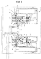
- the switchgear 1 of vacuum insulation type includes two switch units 1a, 1b, two bus portions 2a, 2b, the solid insulated conductor 3 for connecting those two switch units 1a, 1b, the cable connection portion 4, and the housing 5 which stores the respective units as described above.
- the switch units 1a, 1b are vertically arranged in two upper and lower stack stages in parallel at the same side so that the bus portions 2a, 2b are directed to a back surface of the switchgear.
- the solid insulated conductor 3 is provided between the two switch units 1a and 1b.
- the cable connection portion 4 is provided closer to the back surface than the solid insulated conductor 3 at the same back side as the bus portions 2a, 2b so that the conductor connection portions 15 of the two switch units face with each other.
- the bus portions 2a, 2b are provided at the back side, and the cable connection portion 4 is also provided at the back side as well.
- the bus portions 2a, 2b and the cable connection portion 4 which are expected to be connected upon installation on site may be intensively arranged on the back side of the board. This may improve the installation workability on site.
- two switches are provided in parallel to form a switch unit which is long in its axial direction (longitudinal direction) and short in the direction perpendicular to the longitudinal direction.
- the switch unit is formed into a rectangular parallelepiped which is long in one direction and short in the other direction
- a plurality of such switch units are arranged along the short side of the rectangular parallelepiped.
- the housing that stores the plurality of switch units and the switchgear may be shaped approximately to the cube, thus reducing the volume.
- the plurality of switches are arranged in the stack along the short side (direction perpendicular to the longitudinal direction), ensuring to provide the compact vacuum insulated switchgear.
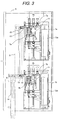
- the second embodiment will be described referring to Fig. 3 .
- the embodiment has a different arrangement of the switch units from that of the embodiment 1.
- the same switch units as those used in the embodiment 1 are employed, and accordingly, the redundant explanation of the switch unit will be omitted.
- the switch units 1a, 1b are arranged in two upper and lower stack stages in the longitudinal direction of the switch units 1a, 1b so that the respective bus connection portions are positioned at the respective tops.
- the solid insulated conductor 3 is provided between the two switch units 1a, 1b, and the respective conductor connection portions 15 are arranged at the back side of the solid insulated conductor 3.
- the respective conductor connection portions 15 are arranged in parallel in a plane, and directed to the same side.
- the conductor connection portions 15 are connected with each another by conductors perpendicular thereto.
- the switchgears are longitudinally arranged in the vertical stack, which may increase the height direction of the board, but may minimize its depth. This makes it possible to provide the vacuum insulated switchgear suitable for installation in the electric chamber with small installation area.
- the respective conductor connection portions 15 are arranged in parallel in the plane, and directed to the same side. They are connected with each another by the solid insulated conductor 3 perpendicular thereto, thus requiring no adapter for connecting the conductive connection portions 15. This makes it possible to reduce the number of components.
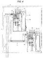
- the third embodiment will be described referring to Fig. 4 .
- the arrangement of the switch units is different from that of the embodiment 1 or 2.
- the same switch unit as that of the embodiment 1 is employed, and accordingly, the explanation of the switch unit will be omitted.
- the switch units 1a, 1b are provided at positions where the switch units 1a, 1b are displaced from the longitudinal direction and the direction perpendicular thereto so that the respective bus connection portions of the switch units 1a, 1b are positioned upward of the switchgear.
- the one at the lower stage side is positioned at the front side of the switchgear, and the one at the upper stage side is positioned at the back side of the switchgear.
- the solid insulated conductor 3 is provided between the aforementioned two switch units 1a, 1b, and the conductor connection portions 15 are arranged at the back side of the solid insulated conductor 3.
- a plurality of switch units 1a, 1b are arranged at the positions displaced from the longitudinal direction and the direction perpendicular thereto so that the space sufficient to allow access to the respective compartments in the switchgear can be secured in spite of increase in the entire dimension of the switchgear. This makes it possible to provide the vacuum insulated switchgear with excellent service and maintenance performance.
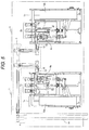
- the fourth embodiment will be described referring to Fig. 5 .
- the arrangement of the switch units is different from that of the respective embodiments.
- the same switch unit as that of the embodiment 1 is employed, and accordingly the explanation of the switch unit will be omitted herein.
- the switch units 1a, 1b are adjacently arranged on the bottom surface of the switchgear on the same level at the front surface side and the back side of the switchgear so that the respective bus connection portions and the conductor connection portions 15 face across the board center.
- the solid insulated conductor 3 is provided between the two switch units, and the cable connection portion 4 is arranged at the back side of the solid insulated conductor 3.
- a plurality of switch units are adjacently arranged on the bottom surface of the switchgear so as to minimize the height of the board, and lower the gravity center of the switchgear.
- This makes it possible to provide the vacuum insulated switchgear suitable for installation in the electric chamber with limited height and in the region required to have seismic capacity.
- a certain effect may be obtained in terms of seismic capacity by arranging the plurality of switch units at the lower portion, specifically, at the position where the height center of the switch unit becomes half the height of the switchgear or less.
- the similar effect may be derived from the embodiments 5 and 6 as described below.
- the cable connection portion is positioned at the back side of the board, which allows easy cable installation on site.
- the respective bus connection portions and the conductor connection portions 15 are arranged to face across the board center, which may intensively arrange the bus portions for installation on site, thus contributing to improved workability.
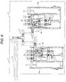
- the fifth embodiment will be described referring to Fig. 6 .
- the arrangement of the switch units is different from that of the respective embodiments as described above.
- the same switch unit as that of the embodiment 1 is employed, and accordingly, the explanation of the switch unit will be omitted herein.
- the switch units 1a, 1b are arranged at the front side and the back side of the switchgear, respectively so that the respective bus connection portions and the conductor connection portions 15 face across the board center.
- the solid insulated conductor 3 is provided between the two switch units, and the cable connection portion 4 is provided above the solid insulated conductor 3.
- a plurality of switch units are adjacently provided at the lower portion of the switchgear on the different level.
- this embodiment allows the height of the board to be reduced, and the gravity center of the switchgear to be lowered. It is therefore possible to provide the vacuum insulated switchgear suitable for installation in the electric chamber with limited height and in the area required to have seismic capacity.
- the embodiment has the plurality of switch units adjacently arranged at the lower portion of the switchgear on the different level. Even if the dimension in the width direction (lateral direction shown in Fig. 6 ) is reduced for installation of the conductor connection portion 15, the conductor connection portion 15 of the other switch unit may cause no interference. This may reduce the depth of the switchgear, and accordingly, it is possible to provide the excellent vacuum insulated switchgear suitable for the place where it is difficult to have sufficient space for the electric chamber, which requires reduction in the installation area.
- the respective bus connection portions and the conductor connection portions 15 are arranged to face across the board center, which may intensively arrange the positions of the bus portions for installation on site, thus contributing to the improved workability.
- the switch units 1a, 1b are adjacently arranged on the bottom surface of the switchgear at its front and back sides, respectively so that the respective bus connection portions and the conductor connection portions 15 face across the board center.
- the conductor connection portions 15 are adjacently arranged.
- the solid insulated conductor 3 is not provided between the two switch units, and the conductor connection portions 15 and the cable connection adapter 16 are connected.
- the plurality of switch units are adjacently arranged at the lower portion of the switchgear on the same level.
- the switch units 1a, 1b are arranged so that the cable connection portions are alternately (zigzag) positioned in the board depth direction.
- cable terminals connected to the switch units 1a, 1b are connected to the single cable via the cable connection adapter 16.
- the embodiment 4 has the switch units 1a, 1b adjacently arranged on the bottom surface of the switchgear at its front side and the back side, respectively.
- a certain effect may be obtained in terms of seismic capacity by arranging a plurality of switch units at the lower portion, specifically at the position where the height center of the switch unit becomes half the height of the switchgear or less.
- the switch units 1a, 1b are alternately (zigzag) arranged to reduce the depth of the board, aiming at reduction in the installation area.
- the conductor connection portions 15 are adjacently arranged so that the conductor connection portions 15 and the cable connection adapter 16 are connected, which then may be connected to the cable side without providing the solid insulated conductor 3 between the switch units.
- This may eliminate the solid insulated conductor 3 for connecting the switch units while being required in the other embodiments, thus aiming at reduction in the number of components.
- the cable connection adapter 16 by itself is a component generally used for constructing the cable by the contractor, it is to be understood that it does not have to be newly manufactured by the switchgear maker. So the number of the components may be reduced, and the work for the cable connection may be easily done on site.
- the conductor connection portions 15 are adjacently arranged in the embodiment so as to connect the conductor connectionportions 15 to the cable connection adapter 16, which ensures connection to the cable side.
- Arrangement of the switch units on the same level is not an indispensable condition as described herein. The arrangement of the switch units on the same level allows each of the conductive connection portions 15 to have the same structure (no need of length adjustment), thus improving productivity.
Landscapes
- Engineering & Computer Science (AREA)
- Power Engineering (AREA)
- Gas-Insulated Switchgears (AREA)
- Patch Boards (AREA)
Claims (14)
- Appareillage de commutation comprenant :une pluralité d'unités de commutateur compatibles (1a, 1b) prévues dans un boîtier (5), chacune des unités de commutateur incluant un ou plusieurs commutateurs (6a, 6b, 7a, 7b) et une douille de connexion de bus (9) connectée à un côté bus et permettant la commutation entre des fonctions de fermeture/interruption/mise à la terre,dans lequella pluralité d'unités de commutateur (1a, 1b) sont connectées électriquement les unes aux autres du côté de la charge du commutateur.
- Appareillage de commutation selon la revendication 1,
dans lequel l'unité de commutateur compatible (1a, 1b) est configurée comme une unité à remplacer quand l'unité de commutateur (la, 1b) est hors service. - Appareillage de commutation selon la revendication 1 ou 2,
dans lequel les commutateurs (6a, 6b, 7a, 7b) inclus dans l'unité de commutateur compatible respective (la, 1b) sont moulés de manière intégrale au moyen d'une résine époxy (11), respectivement de telle manière que des commutateurs moulés (1aa, 1ba) sont formés. - Appareillage de commutation selon la revendication 1,
dans lequel chacune des unités de commutateur inclut en outre une fonction de déconnexion. - Appareillage de commutation selon la revendication 1 ou 4, dans lequel :chacune des unités de commutateur (1a, 1b) inclut en outre une portion de connexion conductrice (15) connectée à un câble du côté de la charge ;les douilles de connexion de bus (9) prévues dans chacune des unités de commutateur (1a, 1b) sont respectivement agencées sensiblement sur le même côté ;une pluralité des portions de connexion conductrices (15) sont agencées mutuellement face-à-face ; etles douilles de connexion de bus (9) et le câble du côté de la charge sont en outre agencés sensiblement sur le même côté.
- Appareillage de commutation selon l'une au moins des revendications 1, 4 ou 5,
dans lequel la pluralité d'unités de commutateur (1a, 1b) sont agencées dans un empilement dans une direction sensiblement perpendiculaire à une direction longitudinale de l'unité de commutateur (1a, 1b). - Appareillage de commutation selon la revendication 1 ou 4, dans lequel
chacune des unités de commutateur (1a, 1b) inclut en outre une portion de connexion conductrice (15) connectée à un câble du côté de la charge ; et
la pluralité d'unités de commutateur (1a, 1b) sont empilées dans une direction longitudinale de l'unité de commutateur (1a, 1b). - Appareillage de commutation selon la revendication 7,
dans lequel une pluralité des portions de connexion conductrices (15) sont agencées en parallèle dans un plan et sensiblement sur le même côté, et sont connectées par un conducteur sensiblement perpendiculaire à la pluralité de portions de connexion conductrices (15). - Appareillage de commutation selon la revendication 1 ou 4,
dans lequel la pluralité d'unités de commutateur (1a, 1b) sont agencées à des positions déplacées depuis une direction longitudinale de l'unité de commutateur (1a, 1b) et une direction sensiblement perpendiculaire à la direction longitudinale. - Appareillage de commutation selon la revendication 1 ou 4,
dans lequel la pluralité d'unités de commutateur (1a, 1b) sont agencées de manière adjacente à une portion inférieure de l'appareillage de commutation (1) sensiblement sur le même niveau. - Appareillage de commutation selon la revendication 10,
dans lequel chacune des unités de commutateur (1a, 1b) inclut une portion de connexion conductrice (15) connectée à un câble du côté de la charge ; et
une pluralité des portions de connexion conductrices (15) sont agencées mutuellement en face-à-face. - Appareillage de commutation selon la revendication 1 ou 4,
dans lequel la pluralité d'unités de commutateur (1a, 1b) sont agencées de manière adjacente à une portion inférieure de l'appareillage (1) sur un niveau différent. - Appareillage de commutation selon la revendication 12,
dans lequel chacune des unités de commutateur (1a, 1b) inclut une portion de connexion conductrice (15) connectée à un câble du côté de la charge ; et
une pluralité des portions de connexion conductrices (15) sont agencées du même côté vers lequel la pluralité de portions de connexion conductrice (15) font face. - Appareillage de commutation selon l'une au moins des revendications 5 à 8, 11 ou 13,
dans lequel la pluralité de portions de connexion conductrices (15) sont agencées de manière adjacente.
Applications Claiming Priority (1)
| Application Number | Priority Date | Filing Date | Title |
|---|---|---|---|
| JP2010282532A JP5211147B2 (ja) | 2010-12-20 | 2010-12-20 | スイッチギヤ |
Publications (3)
| Publication Number | Publication Date |
|---|---|
| EP2485348A2 EP2485348A2 (fr) | 2012-08-08 |
| EP2485348A3 EP2485348A3 (fr) | 2013-01-23 |
| EP2485348B1 true EP2485348B1 (fr) | 2016-10-19 |
Family
ID=45421935
Family Applications (1)
| Application Number | Title | Priority Date | Filing Date |
|---|---|---|---|
| EP11194592.9A Not-in-force EP2485348B1 (fr) | 2010-12-20 | 2011-12-20 | Appareillage de commutation |
Country Status (8)
| Country | Link |
|---|---|
| US (1) | US8791379B2 (fr) |
| EP (1) | EP2485348B1 (fr) |
| JP (1) | JP5211147B2 (fr) |
| KR (1) | KR101286812B1 (fr) |
| CN (1) | CN102570340A (fr) |
| MY (1) | MY158302A (fr) |
| SG (1) | SG182112A1 (fr) |
| TW (1) | TWI442661B (fr) |
Families Citing this family (43)
| Publication number | Priority date | Publication date | Assignee | Title |
|---|---|---|---|---|
| JP5905779B2 (ja) * | 2012-06-13 | 2016-04-20 | 株式会社日立製作所 | 抵抗器及びそれを備えたスイッチギヤ |
| JP2014096914A (ja) * | 2012-11-09 | 2014-05-22 | Hitachi Ltd | スイッチギヤまたはスイッチギヤ内の遮断器交換方法 |
| US11959371B2 (en) | 2012-11-16 | 2024-04-16 | Us Well Services, Llc | Suction and discharge lines for a dual hydraulic fracturing unit |
| US9995218B2 (en) | 2012-11-16 | 2018-06-12 | U.S. Well Services, LLC | Turbine chilling for oil field power generation |
| US9650879B2 (en) | 2012-11-16 | 2017-05-16 | Us Well Services Llc | Torsional coupling for electric hydraulic fracturing fluid pumps |
| US9970278B2 (en) | 2012-11-16 | 2018-05-15 | U.S. Well Services, LLC | System for centralized monitoring and control of electric powered hydraulic fracturing fleet |
| US11476781B2 (en) | 2012-11-16 | 2022-10-18 | U.S. Well Services, LLC | Wireline power supply during electric powered fracturing operations |
| US9745840B2 (en) | 2012-11-16 | 2017-08-29 | Us Well Services Llc | Electric powered pump down |
| US11449018B2 (en) | 2012-11-16 | 2022-09-20 | U.S. Well Services, LLC | System and method for parallel power and blackout protection for electric powered hydraulic fracturing |
| US10036238B2 (en) | 2012-11-16 | 2018-07-31 | U.S. Well Services, LLC | Cable management of electric powered hydraulic fracturing pump unit |
| US10254732B2 (en) | 2012-11-16 | 2019-04-09 | U.S. Well Services, Inc. | Monitoring and control of proppant storage from a datavan |
| US10119381B2 (en) | 2012-11-16 | 2018-11-06 | U.S. Well Services, LLC | System for reducing vibrations in a pressure pumping fleet |
| US10232332B2 (en) | 2012-11-16 | 2019-03-19 | U.S. Well Services, Inc. | Independent control of auger and hopper assembly in electric blender system |
| US10407990B2 (en) | 2012-11-16 | 2019-09-10 | U.S. Well Services, LLC | Slide out pump stand for hydraulic fracturing equipment |
| US10020711B2 (en) | 2012-11-16 | 2018-07-10 | U.S. Well Services, LLC | System for fueling electric powered hydraulic fracturing equipment with multiple fuel sources |
| US9893500B2 (en) | 2012-11-16 | 2018-02-13 | U.S. Well Services, LLC | Switchgear load sharing for oil field equipment |
| US9410410B2 (en) | 2012-11-16 | 2016-08-09 | Us Well Services Llc | System for pumping hydraulic fracturing fluid using electric pumps |
| US11181107B2 (en) | 2016-12-02 | 2021-11-23 | U.S. Well Services, LLC | Constant voltage power distribution system for use with an electric hydraulic fracturing system |
| US11289884B2 (en) | 2017-06-16 | 2022-03-29 | Eaton Intelligent Power Limited | Isolating bus enclosure arrangements for switchgear |
| US10164412B1 (en) * | 2017-06-16 | 2018-12-25 | Eaton Intelligent Power Limited | Switchgear with a two-high circuit interrupter configuration |
| US10158214B1 (en) * | 2017-06-16 | 2018-12-18 | Eaton Intelligent Power Limited | Switchgear with modular bus configuration supporting individual and parallel feed arrangements |
| WO2018232236A1 (fr) | 2017-06-16 | 2018-12-20 | Eaton Intelligent Power Limited | Agencements de bus isolés au gaz isolant pour appareillage de commutation |
| AR113285A1 (es) | 2017-10-05 | 2020-03-11 | U S Well Services Llc | Método y sistema de flujo de lodo de fractura instrumentada |
| WO2019075475A1 (fr) | 2017-10-13 | 2019-04-18 | U.S. Well Services, LLC | Système et procédé de fracturation automatique |
| AR114805A1 (es) | 2017-10-25 | 2020-10-21 | U S Well Services Llc | Método y sistema de fracturación inteligente |
| CA3084607A1 (fr) | 2017-12-05 | 2019-06-13 | U.S. Well Services, LLC | Configuration de pompage de puissance elevee pour un systeme de fracturation hydraulique electrique |
| US10598258B2 (en) | 2017-12-05 | 2020-03-24 | U.S. Well Services, LLC | Multi-plunger pumps and associated drive systems |
| US11114857B2 (en) | 2018-02-05 | 2021-09-07 | U.S. Well Services, LLC | Microgrid electrical load management |
| CA3097051A1 (fr) | 2018-04-16 | 2019-10-24 | U.S. Well Services, LLC | Parc de fracturation hydraulique hybride |
| US10608393B2 (en) * | 2018-04-17 | 2020-03-31 | S&C Electric Company | Cable center line adapters for switchgear retro-fit applications |
| WO2019241783A1 (fr) | 2018-06-15 | 2019-12-19 | U.S. Well Services, Inc. | Unité d'alimentation mobile intégrée pour fracturation hydraulique |
| WO2020056258A1 (fr) | 2018-09-14 | 2020-03-19 | U.S. Well Services, LLC | Support de colonne montante pour sites de puits |
| WO2020076902A1 (fr) | 2018-10-09 | 2020-04-16 | U.S. Well Services, LLC | Système de commutation modulaire et distribution d'énergie pour équipement électrique de champ pétrolifère |
| WO2020081313A1 (fr) | 2018-10-09 | 2020-04-23 | U.S. Well Services, LLC | Système de pompe de fracturation hydraulique électrique comprenant des remorques de fracturation pour pompe à pistons multiples à alimentation électrique unique, unités de filtration, et plate-forme coulissante |
| US11578577B2 (en) | 2019-03-20 | 2023-02-14 | U.S. Well Services, LLC | Oversized switchgear trailer for electric hydraulic fracturing |
| US11728709B2 (en) | 2019-05-13 | 2023-08-15 | U.S. Well Services, LLC | Encoderless vector control for VFD in hydraulic fracturing applications |
| US11506126B2 (en) | 2019-06-10 | 2022-11-22 | U.S. Well Services, LLC | Integrated fuel gas heater for mobile fuel conditioning equipment |
| WO2021022048A1 (fr) | 2019-08-01 | 2021-02-04 | U.S. Well Services, LLC | Système de stockage d'énergie à haute capacité pour fracturation hydraulique électrique |
| US11459863B2 (en) | 2019-10-03 | 2022-10-04 | U.S. Well Services, LLC | Electric powered hydraulic fracturing pump system with single electric powered multi-plunger fracturing pump |
| EP3836182B1 (fr) * | 2019-12-11 | 2023-03-08 | ABB Schweiz AG | Commutateur de déconnexion à trois positions |
| US11009162B1 (en) | 2019-12-27 | 2021-05-18 | U.S. Well Services, LLC | System and method for integrated flow supply line |
| WO2022178963A1 (fr) * | 2021-02-25 | 2022-09-01 | Jst Power Equipment, Inc. | Système d'appareillage de commutation ayant un disjoncteur entraîné par chaîne et procédés associés |
| MX2023009869A (es) | 2021-02-25 | 2023-08-29 | Jst Power Equipment Inc | Sistema de conmutacion de media tension con control de disyuntor monofasico. |
Family Cites Families (17)
| Publication number | Priority date | Publication date | Assignee | Title |
|---|---|---|---|---|
| DE1016794B (de) | 1952-09-26 | 1957-10-03 | Calor Emag Elektrizitaets Ag | Zweireihige Schaltanlage der Zellenbauweise mit Doppelsammelschienen |
| JPH0476108A (ja) | 1990-07-17 | 1992-03-10 | Seiji Ichikawa | グラウト方法 |
| JPH0476108U (fr) * | 1990-11-08 | 1992-07-02 | ||
| JP3507629B2 (ja) | 1996-09-06 | 2004-03-15 | 株式会社東芝 | スイッチギヤ |
| JP4072236B2 (ja) | 1998-03-25 | 2008-04-09 | 株式会社日立製作所 | ガス絶縁開閉装置 |
| US6556428B1 (en) | 2002-01-14 | 2003-04-29 | Hitachi, Ltd. | Gas insulated switchgear |
| JP2003299216A (ja) | 2002-03-29 | 2003-10-17 | Toshiba Corp | ガス絶縁開閉装置 |
| KR20040013093A (ko) | 2002-04-12 | 2004-02-11 | 미쓰비시덴키 가부시키가이샤 | 금속폐쇄형 배전반 |
| DE10314458A1 (de) | 2003-03-28 | 2004-10-07 | Alstom | Metallgekapselte gasisolierte Schaltanlage |
| CN200953435Y (zh) * | 2006-08-03 | 2007-09-26 | 成都尤立科电器有限公司 | 旋转升降式户内电源开关箱 |
| ES2322828B2 (es) | 2006-09-21 | 2010-04-07 | Ormazabal Distribucion Primaria, S.A. | Aparamenta modular de distribucion electrica. |
| JP4339372B2 (ja) * | 2007-03-27 | 2009-10-07 | 株式会社日立製作所 | 真空絶縁スイッチギヤ |
| JP4906755B2 (ja) * | 2008-02-22 | 2012-03-28 | 株式会社日立製作所 | 金属閉鎖形スイッチギア |
| JP4633145B2 (ja) | 2008-07-07 | 2011-02-16 | 株式会社日立製作所 | 固体絶縁母線スイッチギヤ |
| JP5087494B2 (ja) * | 2008-08-06 | 2012-12-05 | 株式会社東芝 | 固体絶縁スイッチギヤ |
| JP4764906B2 (ja) | 2008-08-12 | 2011-09-07 | 株式会社日立製作所 | 真空スイッチ及び真空スイッチギヤ |
| JP5181003B2 (ja) * | 2010-08-23 | 2013-04-10 | 株式会社日立製作所 | スイッチギヤ |
-
2010
- 2010-12-20 JP JP2010282532A patent/JP5211147B2/ja not_active Expired - Fee Related
-
2011
- 2011-12-06 TW TW100144833A patent/TWI442661B/zh not_active IP Right Cessation
- 2011-12-06 US US13/311,587 patent/US8791379B2/en not_active Expired - Fee Related
- 2011-12-15 KR KR1020110135012A patent/KR101286812B1/ko not_active IP Right Cessation
- 2011-12-16 CN CN2011104250426A patent/CN102570340A/zh active Pending
- 2011-12-19 SG SG2011094471A patent/SG182112A1/en unknown
- 2011-12-20 MY MYPI2011006181A patent/MY158302A/en unknown
- 2011-12-20 EP EP11194592.9A patent/EP2485348B1/fr not_active Not-in-force
Also Published As
| Publication number | Publication date |
|---|---|
| EP2485348A2 (fr) | 2012-08-08 |
| CN102570340A (zh) | 2012-07-11 |
| TW201240253A (en) | 2012-10-01 |
| JP2012135068A (ja) | 2012-07-12 |
| MY158302A (en) | 2016-09-30 |
| US20120152716A1 (en) | 2012-06-21 |
| KR20120069572A (ko) | 2012-06-28 |
| TWI442661B (zh) | 2014-06-21 |
| US8791379B2 (en) | 2014-07-29 |
| EP2485348A3 (fr) | 2013-01-23 |
| KR101286812B1 (ko) | 2013-07-17 |
| SG182112A1 (en) | 2012-07-30 |
| JP5211147B2 (ja) | 2013-06-12 |
Similar Documents
| Publication | Publication Date | Title |
|---|---|---|
| EP2485348B1 (fr) | Appareillage de commutation | |
| US8008594B2 (en) | Vacuum insulated switchgear | |
| US8248760B2 (en) | Switch arrangement for an electrical switchgear | |
| CN101540484B (zh) | 开关机构 | |
| EP3062403B1 (fr) | Appareillage de commutation à isolation par gaz | |
| CN111342384B (zh) | 三相开关装置或控制装置 | |
| US7903394B2 (en) | Gas-insulated switchgear | |
| JP5484638B2 (ja) | ガス絶縁開閉装置 | |
| US9472926B2 (en) | Gas-insulated switchgear arrangement | |
| WO2018231357A1 (fr) | Appareillage de commutation à configuration double-bus | |
| US10164412B1 (en) | Switchgear with a two-high circuit interrupter configuration | |
| US9355792B2 (en) | Gas insulated switchgear | |
| US20050213288A1 (en) | High voltage outdoor substation | |
| US8462485B2 (en) | Switchgear for underground electric power distribution line | |
| EP3883074A1 (fr) | Appareillage de commutation électrique pour des applications en basse et moyenne tension | |
| EP3869646B1 (fr) | Appareillage de commutation électrique pour applications en basse et moyenne tension | |
| KR830002148B1 (ko) | 가스절연 개폐장치 | |
| JP2011234463A (ja) | ガス絶縁スイッチギヤ | |
| JPH08275322A (ja) | ガス絶縁開閉装置 | |
| JPH0824406B2 (ja) | ガス絶縁開閉装置 | |
| Sölver | Hybrid Designs for Open Air Substations | |
| JPS62244206A (ja) | ガス絶縁複合開閉装置 |
Legal Events
| Date | Code | Title | Description |
|---|---|---|---|
| PUAI | Public reference made under article 153(3) epc to a published international application that has entered the european phase |
Free format text: ORIGINAL CODE: 0009012 |
|
| 17P | Request for examination filed |
Effective date: 20120302 |
|
| AK | Designated contracting states |
Kind code of ref document: A2 Designated state(s): AL AT BE BG CH CY CZ DE DK EE ES FI FR GB GR HR HU IE IS IT LI LT LU LV MC MK MT NL NO PL PT RO RS SE SI SK SM TR |
|
| AX | Request for extension of the european patent |
Extension state: BA ME |
|
| RIN1 | Information on inventor provided before grant (corrected) |
Inventor name: TAKAHASHI, KEIICHI Inventor name: TSUCHIYA, KENJI Inventor name: MORITA, AYUMU Inventor name: KIKUKAWA, SHUICHI |
|
| PUAL | Search report despatched |
Free format text: ORIGINAL CODE: 0009013 |
|
| AK | Designated contracting states |
Kind code of ref document: A3 Designated state(s): AL AT BE BG CH CY CZ DE DK EE ES FI FR GB GR HR HU IE IS IT LI LT LU LV MC MK MT NL NO PL PT RO RS SE SI SK SM TR |
|
| AX | Request for extension of the european patent |
Extension state: BA ME |
|
| RIC1 | Information provided on ipc code assigned before grant |
Ipc: H02B 1/22 20060101AFI20121218BHEP |
|
| GRAP | Despatch of communication of intention to grant a patent |
Free format text: ORIGINAL CODE: EPIDOSNIGR1 |
|
| RIC1 | Information provided on ipc code assigned before grant |
Ipc: H02B 1/22 20060101AFI20160322BHEP Ipc: H02B 13/01 20060101ALI20160322BHEP |
|
| INTG | Intention to grant announced |
Effective date: 20160426 |
|
| GRAS | Grant fee paid |
Free format text: ORIGINAL CODE: EPIDOSNIGR3 |
|
| GRAA | (expected) grant |
Free format text: ORIGINAL CODE: 0009210 |
|
| AK | Designated contracting states |
Kind code of ref document: B1 Designated state(s): AL AT BE BG CH CY CZ DE DK EE ES FI FR GB GR HR HU IE IS IT LI LT LU LV MC MK MT NL NO PL PT RO RS SE SI SK SM TR |
|
| REG | Reference to a national code |
Ref country code: GB Ref legal event code: FG4D |
|
| REG | Reference to a national code |
Ref country code: CH Ref legal event code: EP |
|
| REG | Reference to a national code |
Ref country code: AT Ref legal event code: REF Ref document number: 839070 Country of ref document: AT Kind code of ref document: T Effective date: 20161115 |
|
| REG | Reference to a national code |
Ref country code: IE Ref legal event code: FG4D |
|
| REG | Reference to a national code |
Ref country code: DE Ref legal event code: R096 Ref document number: 602011031407 Country of ref document: DE |
|
| REG | Reference to a national code |
Ref country code: FR Ref legal event code: PLFP Year of fee payment: 6 |
|
| PGFP | Annual fee paid to national office [announced via postgrant information from national office to epo] |
Ref country code: CH Payment date: 20161222 Year of fee payment: 6 |
|
| REG | Reference to a national code |
Ref country code: NL Ref legal event code: MP Effective date: 20161019 |
|
| REG | Reference to a national code |
Ref country code: LT Ref legal event code: MG4D |
|
| PG25 | Lapsed in a contracting state [announced via postgrant information from national office to epo] |
Ref country code: LV Free format text: LAPSE BECAUSE OF FAILURE TO SUBMIT A TRANSLATION OF THE DESCRIPTION OR TO PAY THE FEE WITHIN THE PRESCRIBED TIME-LIMIT Effective date: 20161019 |
|
| PGFP | Annual fee paid to national office [announced via postgrant information from national office to epo] |
Ref country code: FR Payment date: 20161221 Year of fee payment: 6 |
|
| RAP2 | Party data changed (patent owner data changed or rights of a patent transferred) |
Owner name: HITACHI INDUSTRIAL EQUIPMENT SYSTEMS CO., LTD. |
|
| REG | Reference to a national code |
Ref country code: AT Ref legal event code: MK05 Ref document number: 839070 Country of ref document: AT Kind code of ref document: T Effective date: 20161019 |
|
| PG25 | Lapsed in a contracting state [announced via postgrant information from national office to epo] |
Ref country code: NO Free format text: LAPSE BECAUSE OF FAILURE TO SUBMIT A TRANSLATION OF THE DESCRIPTION OR TO PAY THE FEE WITHIN THE PRESCRIBED TIME-LIMIT Effective date: 20170119 Ref country code: GR Free format text: LAPSE BECAUSE OF FAILURE TO SUBMIT A TRANSLATION OF THE DESCRIPTION OR TO PAY THE FEE WITHIN THE PRESCRIBED TIME-LIMIT Effective date: 20170120 Ref country code: LT Free format text: LAPSE BECAUSE OF FAILURE TO SUBMIT A TRANSLATION OF THE DESCRIPTION OR TO PAY THE FEE WITHIN THE PRESCRIBED TIME-LIMIT Effective date: 20161019 Ref country code: SE Free format text: LAPSE BECAUSE OF FAILURE TO SUBMIT A TRANSLATION OF THE DESCRIPTION OR TO PAY THE FEE WITHIN THE PRESCRIBED TIME-LIMIT Effective date: 20161019 |
|
| PGFP | Annual fee paid to national office [announced via postgrant information from national office to epo] |
Ref country code: DE Payment date: 20161231 Year of fee payment: 6 |
|
| PG25 | Lapsed in a contracting state [announced via postgrant information from national office to epo] |
Ref country code: PL Free format text: LAPSE BECAUSE OF FAILURE TO SUBMIT A TRANSLATION OF THE DESCRIPTION OR TO PAY THE FEE WITHIN THE PRESCRIBED TIME-LIMIT Effective date: 20161019 Ref country code: NL Free format text: LAPSE BECAUSE OF FAILURE TO SUBMIT A TRANSLATION OF THE DESCRIPTION OR TO PAY THE FEE WITHIN THE PRESCRIBED TIME-LIMIT Effective date: 20161019 Ref country code: AT Free format text: LAPSE BECAUSE OF FAILURE TO SUBMIT A TRANSLATION OF THE DESCRIPTION OR TO PAY THE FEE WITHIN THE PRESCRIBED TIME-LIMIT Effective date: 20161019 Ref country code: PT Free format text: LAPSE BECAUSE OF FAILURE TO SUBMIT A TRANSLATION OF THE DESCRIPTION OR TO PAY THE FEE WITHIN THE PRESCRIBED TIME-LIMIT Effective date: 20170220 Ref country code: ES Free format text: LAPSE BECAUSE OF FAILURE TO SUBMIT A TRANSLATION OF THE DESCRIPTION OR TO PAY THE FEE WITHIN THE PRESCRIBED TIME-LIMIT Effective date: 20161019 Ref country code: FI Free format text: LAPSE BECAUSE OF FAILURE TO SUBMIT A TRANSLATION OF THE DESCRIPTION OR TO PAY THE FEE WITHIN THE PRESCRIBED TIME-LIMIT Effective date: 20161019 Ref country code: BE Free format text: LAPSE BECAUSE OF FAILURE TO SUBMIT A TRANSLATION OF THE DESCRIPTION OR TO PAY THE FEE WITHIN THE PRESCRIBED TIME-LIMIT Effective date: 20161019 Ref country code: IS Free format text: LAPSE BECAUSE OF FAILURE TO SUBMIT A TRANSLATION OF THE DESCRIPTION OR TO PAY THE FEE WITHIN THE PRESCRIBED TIME-LIMIT Effective date: 20170219 Ref country code: HR Free format text: LAPSE BECAUSE OF FAILURE TO SUBMIT A TRANSLATION OF THE DESCRIPTION OR TO PAY THE FEE WITHIN THE PRESCRIBED TIME-LIMIT Effective date: 20161019 Ref country code: RS Free format text: LAPSE BECAUSE OF FAILURE TO SUBMIT A TRANSLATION OF THE DESCRIPTION OR TO PAY THE FEE WITHIN THE PRESCRIBED TIME-LIMIT Effective date: 20161019 |
|
| REG | Reference to a national code |
Ref country code: DE Ref legal event code: R097 Ref document number: 602011031407 Country of ref document: DE |
|
| PG25 | Lapsed in a contracting state [announced via postgrant information from national office to epo] |
Ref country code: RO Free format text: LAPSE BECAUSE OF FAILURE TO SUBMIT A TRANSLATION OF THE DESCRIPTION OR TO PAY THE FEE WITHIN THE PRESCRIBED TIME-LIMIT Effective date: 20161019 Ref country code: DK Free format text: LAPSE BECAUSE OF FAILURE TO SUBMIT A TRANSLATION OF THE DESCRIPTION OR TO PAY THE FEE WITHIN THE PRESCRIBED TIME-LIMIT Effective date: 20161019 Ref country code: CZ Free format text: LAPSE BECAUSE OF FAILURE TO SUBMIT A TRANSLATION OF THE DESCRIPTION OR TO PAY THE FEE WITHIN THE PRESCRIBED TIME-LIMIT Effective date: 20161019 Ref country code: SK Free format text: LAPSE BECAUSE OF FAILURE TO SUBMIT A TRANSLATION OF THE DESCRIPTION OR TO PAY THE FEE WITHIN THE PRESCRIBED TIME-LIMIT Effective date: 20161019 Ref country code: EE Free format text: LAPSE BECAUSE OF FAILURE TO SUBMIT A TRANSLATION OF THE DESCRIPTION OR TO PAY THE FEE WITHIN THE PRESCRIBED TIME-LIMIT Effective date: 20161019 |
|
| PLBE | No opposition filed within time limit |
Free format text: ORIGINAL CODE: 0009261 |
|
| STAA | Information on the status of an ep patent application or granted ep patent |
Free format text: STATUS: NO OPPOSITION FILED WITHIN TIME LIMIT |
|
| PG25 | Lapsed in a contracting state [announced via postgrant information from national office to epo] |
Ref country code: SM Free format text: LAPSE BECAUSE OF FAILURE TO SUBMIT A TRANSLATION OF THE DESCRIPTION OR TO PAY THE FEE WITHIN THE PRESCRIBED TIME-LIMIT Effective date: 20161019 Ref country code: IT Free format text: LAPSE BECAUSE OF FAILURE TO SUBMIT A TRANSLATION OF THE DESCRIPTION OR TO PAY THE FEE WITHIN THE PRESCRIBED TIME-LIMIT Effective date: 20161019 Ref country code: BG Free format text: LAPSE BECAUSE OF FAILURE TO SUBMIT A TRANSLATION OF THE DESCRIPTION OR TO PAY THE FEE WITHIN THE PRESCRIBED TIME-LIMIT Effective date: 20170119 |
|
| 26N | No opposition filed |
Effective date: 20170720 |
|
| GBPC | Gb: european patent ceased through non-payment of renewal fee |
Effective date: 20170119 |
|
| PG25 | Lapsed in a contracting state [announced via postgrant information from national office to epo] |
Ref country code: MC Free format text: LAPSE BECAUSE OF FAILURE TO SUBMIT A TRANSLATION OF THE DESCRIPTION OR TO PAY THE FEE WITHIN THE PRESCRIBED TIME-LIMIT Effective date: 20161019 |
|
| REG | Reference to a national code |
Ref country code: IE Ref legal event code: MM4A |
|
| PG25 | Lapsed in a contracting state [announced via postgrant information from national office to epo] |
Ref country code: LU Free format text: LAPSE BECAUSE OF NON-PAYMENT OF DUE FEES Effective date: 20161220 |
|
| PG25 | Lapsed in a contracting state [announced via postgrant information from national office to epo] |
Ref country code: GB Free format text: LAPSE BECAUSE OF NON-PAYMENT OF DUE FEES Effective date: 20170119 Ref country code: SI Free format text: LAPSE BECAUSE OF FAILURE TO SUBMIT A TRANSLATION OF THE DESCRIPTION OR TO PAY THE FEE WITHIN THE PRESCRIBED TIME-LIMIT Effective date: 20161019 Ref country code: IE Free format text: LAPSE BECAUSE OF NON-PAYMENT OF DUE FEES Effective date: 20161220 |
|
| PG25 | Lapsed in a contracting state [announced via postgrant information from national office to epo] |
Ref country code: CY Free format text: LAPSE BECAUSE OF FAILURE TO SUBMIT A TRANSLATION OF THE DESCRIPTION OR TO PAY THE FEE WITHIN THE PRESCRIBED TIME-LIMIT Effective date: 20161019 Ref country code: HU Free format text: LAPSE BECAUSE OF FAILURE TO SUBMIT A TRANSLATION OF THE DESCRIPTION OR TO PAY THE FEE WITHIN THE PRESCRIBED TIME-LIMIT; INVALID AB INITIO Effective date: 20111220 |
|
| PG25 | Lapsed in a contracting state [announced via postgrant information from national office to epo] |
Ref country code: TR Free format text: LAPSE BECAUSE OF FAILURE TO SUBMIT A TRANSLATION OF THE DESCRIPTION OR TO PAY THE FEE WITHIN THE PRESCRIBED TIME-LIMIT Effective date: 20161019 Ref country code: MK Free format text: LAPSE BECAUSE OF FAILURE TO SUBMIT A TRANSLATION OF THE DESCRIPTION OR TO PAY THE FEE WITHIN THE PRESCRIBED TIME-LIMIT Effective date: 20161019 |
|
| REG | Reference to a national code |
Ref country code: DE Ref legal event code: R119 Ref document number: 602011031407 Country of ref document: DE |
|
| REG | Reference to a national code |
Ref country code: CH Ref legal event code: PL |
|
| PG25 | Lapsed in a contracting state [announced via postgrant information from national office to epo] |
Ref country code: MT Free format text: LAPSE BECAUSE OF NON-PAYMENT OF DUE FEES Effective date: 20161220 |
|
| REG | Reference to a national code |
Ref country code: FR Ref legal event code: ST Effective date: 20180831 |
|
| PG25 | Lapsed in a contracting state [announced via postgrant information from national office to epo] |
Ref country code: FR Free format text: LAPSE BECAUSE OF NON-PAYMENT OF DUE FEES Effective date: 20180102 Ref country code: DE Free format text: LAPSE BECAUSE OF NON-PAYMENT OF DUE FEES Effective date: 20180703 |
|
| PG25 | Lapsed in a contracting state [announced via postgrant information from national office to epo] |
Ref country code: CH Free format text: LAPSE BECAUSE OF NON-PAYMENT OF DUE FEES Effective date: 20171231 Ref country code: LI Free format text: LAPSE BECAUSE OF NON-PAYMENT OF DUE FEES Effective date: 20171231 |
|
| PG25 | Lapsed in a contracting state [announced via postgrant information from national office to epo] |
Ref country code: AL Free format text: LAPSE BECAUSE OF FAILURE TO SUBMIT A TRANSLATION OF THE DESCRIPTION OR TO PAY THE FEE WITHIN THE PRESCRIBED TIME-LIMIT Effective date: 20161019 |