EP2484553B1 - Fahrzeuglampe und optische Einheit dafür - Google Patents
Fahrzeuglampe und optische Einheit dafür Download PDFInfo
- Publication number
- EP2484553B1 EP2484553B1 EP12154292.2A EP12154292A EP2484553B1 EP 2484553 B1 EP2484553 B1 EP 2484553B1 EP 12154292 A EP12154292 A EP 12154292A EP 2484553 B1 EP2484553 B1 EP 2484553B1
- Authority
- EP
- European Patent Office
- Prior art keywords
- light
- light emitting
- reflector
- distribution pattern
- lamp
- Prior art date
- Legal status (The legal status is an assumption and is not a legal conclusion. Google has not performed a legal analysis and makes no representation as to the accuracy of the status listed.)
- Not-in-force
Links
Images


Classifications
-
- B—PERFORMING OPERATIONS; TRANSPORTING
- B60—VEHICLES IN GENERAL
- B60Q—ARRANGEMENT OF SIGNALLING OR LIGHTING DEVICES, THE MOUNTING OR SUPPORTING THEREOF OR CIRCUITS THEREFOR, FOR VEHICLES IN GENERAL
- B60Q1/00—Arrangement of optical signalling or lighting devices, the mounting or supporting thereof or circuits therefor
- B60Q1/0029—Spatial arrangement
- B60Q1/0041—Spatial arrangement of several lamps in relation to each other
-
- F—MECHANICAL ENGINEERING; LIGHTING; HEATING; WEAPONS; BLASTING
- F21—LIGHTING
- F21S—NON-PORTABLE LIGHTING DEVICES; SYSTEMS THEREOF; VEHICLE LIGHTING DEVICES SPECIALLY ADAPTED FOR VEHICLE EXTERIORS
- F21S41/00—Illuminating devices specially adapted for vehicle exteriors, e.g. headlamps
- F21S41/10—Illuminating devices specially adapted for vehicle exteriors, e.g. headlamps characterised by the light source
- F21S41/14—Illuminating devices specially adapted for vehicle exteriors, e.g. headlamps characterised by the light source characterised by the type of light source
- F21S41/141—Light emitting diodes [LED]
- F21S41/147—Light emitting diodes [LED] the main emission direction of the LED being angled to the optical axis of the illuminating device
-
- F—MECHANICAL ENGINEERING; LIGHTING; HEATING; WEAPONS; BLASTING
- F21—LIGHTING
- F21S—NON-PORTABLE LIGHTING DEVICES; SYSTEMS THEREOF; VEHICLE LIGHTING DEVICES SPECIALLY ADAPTED FOR VEHICLE EXTERIORS
- F21S41/00—Illuminating devices specially adapted for vehicle exteriors, e.g. headlamps
- F21S41/30—Illuminating devices specially adapted for vehicle exteriors, e.g. headlamps characterised by reflectors
- F21S41/32—Optical layout thereof
- F21S41/323—Optical layout thereof the reflector having two perpendicular cross sections having regular geometrical curves of a distinct nature
-
- F—MECHANICAL ENGINEERING; LIGHTING; HEATING; WEAPONS; BLASTING
- F21—LIGHTING
- F21S—NON-PORTABLE LIGHTING DEVICES; SYSTEMS THEREOF; VEHICLE LIGHTING DEVICES SPECIALLY ADAPTED FOR VEHICLE EXTERIORS
- F21S45/00—Arrangements within vehicle lighting devices specially adapted for vehicle exteriors, for purposes other than emission or distribution of light
- F21S45/40—Cooling of lighting devices
- F21S45/47—Passive cooling, e.g. using fins, thermal conductive elements or openings
Definitions
- the present invention relates to a vehicle lamp and an optical unit thereof.
- JP2008-226706A and JP2008-226707A disclose paraboloidal reflector type vehicle lamps including a light emitting device and a paraboloidal reflector configured to forwardly reflect light from the light emitting device. These vehicle lamps are configured to form a low-beam light distribution pattern.
- a vehicle headlamp can form a low-beam light distribution pattern and a high-beam light distribution pattern.
- an additional light distribution pattern may be formed in addition to the low-beam light distribution pattern.
- the additional light distribution pattern is formed by, for example, an auxiliary lamp unit provided in the vehicle headlamp in addition to one or more lamp units that forms the low-beam light distribution pattern and the high-beam light distribution pattern.
- the additional light distribution pattern is, for example, a diffused light distribution pattern formed below the horizontal line and having a larger lateral diffusion angle than the low-beam light distribution pattern.
- a lamp unit for forming such a diffused light distribution pattern has, for example, a light emitting device having a rectangular light emitting surface, and a paraboloidal reflector, wherein the light emitting device is disposed at a laterally center position with respect to the reflector such that the long sides of the light emitting surface extend in the horizontal direction.
- the reflector reflects light from the light emitting device such that the long sides of the rectangular light source images of the light emitting surface extend in the horizontal direction and such that the laterally long light source images are laterally and vertically distributed. That is, the reflector is configured to diffuse the light from the light emitting device in vertical and lateral directions. Accordingly, the reflector is wide in both vertical and lateral directions.
- a vehicle lamp including a lamp unit for forming the additional light distribution pattern in addition to one or more lamp units for forming the low-beam light distribution pattern and the high-beam light distribution pattern tends to increase in size.
- a vehicle lamp includes a light emitting device having a rectangular light emitting surface and disposed such that the long sides of the light emitting surface extend in a vertical direction, and a reflector configured to reflect light from the light emitting device in a forward direction of the vehicle lamp to form a horizontally diffused light distribution pattern.
- the reflector is configured to reflect the light from the light emitting device such that the long sides of the light emitting surface are projected to extend in a vertical direction of the horizontally diffused light distribution pattern, and such that, in a top view of the vehicle lamp, a part of the light reflected by one end portion of the reflector and another part of the light reflected by another end portion of the reflector intersect each other.
- an optical unit of the vehicle lamp includes the reflector and a light source mounting portion to which the light emitting device is fixed.
- the optical unit may be suitable for being incorporated into a vehicle lamp according to the aforesaid first aspect of the present invention.
- the optical unit may include a reflector, and a light source mounting portion suitable for fixing a light emitting device having a rectangular light emitting surface to said light source mounting portion; and the optical unit may be configured such that, when the light emitting device is fixed to the light source mounting portion:
- a vehicle lamp 1 according to an exemplary embodiment of the present invention is a vehicle headlamp, which is provided in a pair on each side of a front portion of a vehicle.
- the right and left headlamps have substantially the same configuration, except that they are bilaterally symmetrical.
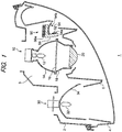
- Fig. 1 illustrates the left headlamp as an example of the vehicle lamp 1.
- the vehicle lamp 1 includes a lamp body 2 having a front opening, and a transparent cover 4 attached to the lamp body 2 to cover the front opening of the lamp body 2.
- the transparent cover 4 is made of a transparent resin, glass or the like.
- a lamp unit 10, a lamp unit 30 and a lamp unit 50 are accommodated in a lamp chamber 3 formed by the lamp body 2 and the transparent cover 4.
- the lamp unit 10, the lamp unit 30 and the lamp unit 50 are attached to the lamp body 2 and supported in the lamp chamber 3 via support members. Because the structures for attaching the lamp units 10, 30. 50 to the lamp body 2 are known, detailed description thereof will be omitted.
- an extension member 6 is also provided inside the lamp chamber 3.
- the extension member 6 has openings in the regions where the lamp units 10, 30, 50 are arranged.
- the extension member 6 is fixed to the lamp body 2.
- the extension member 6 covers a region between the lamp body 2 and the lamp units 10, 30, 50.
- the lamp unit 10 is configured to form a low-beam light distribution pattern.
- the lamp unit 10 is a projector type lamp unit, and includes a light source bulb 12, a reflector 14, a shade 16, a lens holder 18 and a projector lens 20.
- An incandescent lamp or a discharge lamp may be used as the light source bulb 12.
- a light emitting device such as an LED, may be used alternatively as a light source.
- the reflector 14 is formed like a cup, and has an insertion hole at the center.
- the light source bulb 12 is inserted into the insertion hole of the reflector 14, and is fixed to the reflector 14.
- the reflector 14 has an ellipsoidal reflecting surface.
- the light source bulb 12 is disposed at or near the first focal point of the reflecting surface.
- the projector lens 20 is arranged such that the rear focal point of the projector lens 20 is disposed at or near the second focal point of the reflecting surface.
- the shade 16 is like a flat plate, and is provided such that an upper end portion of the shade 16 is located near the second focal point of the reflector 14 or near the rear focal point of the projector lens 20.
- the upper end portion of the shade 16 has a shape that corresponds to a cutoff line of the low-beam light distribution pattern. Direct light from the light source bulb 12 and light reflected by the reflector 14 are partially blocked by the shade 16.
- the projector lens 20 is a planoconvex aspherical lens having a convex front surface and a flat rear surface.
- the projector lens 20 projects a light source image formed on a rear focal plane, which includes the rear focal point of the projector lens 20, as an inverted image on a virtual vertical screen in front of the lamp.
- the projector lens 20 is fixed to a front end portion of the lens holder 18.
- a rear end portion of the lens holder 18 is fixed to a front end portion of the reflector 14.
- the lamp unit 10 may be a paraboloidal reflector type lamp unit, or other types of lamp unit.
- the lamp unit 30 is configured to form a high-beam light distribution pattern.
- the lamp unit 30 is a paraboloidal reflector type lamp unit, and includes a light source bulb 32 and a reflector 34.
- the light source bulb 32 has a similar configuration to that of the light source bulb 12.
- a reflecting surface of the reflector 34 has a portion of a paraboloid of revolution, having a focal point at or near the light source bulb 32, as a reference.
- Light from the light source bulb 32 is forwardly irradiated from the lamp unit 30, either directly from the light source bulb 32 or after being reflected by the reflector 34 to form the high-beam light distribution pattern. Because the high-beam light distribution pattern is known, detailed description thereof will be omitted.
- the lamp unit 30 may be a projector type lamp unit.
- the lamp unit 50 is configured to form a diffused light distribution pattern.
- the diffused light distribution pattern is diffused in the horizontal direction.
- the lamp unit 50 is a paraboloidal reflector type lamp unit, and includes a light source module 52 and an optical unit 54.
- the optical unit 54 has an light source mounting portion 54a and a reflector 54b.
- the light source module 52 is fixed to the light source mounting portion 54a of the optical unit 54.
- the light source mounting portion 54a and the reflector 54b are attached to a heat sink 56.
- the heat sink 56 has a plurality of heat dissipating fins 56a.
- the heat sink 56 is attached to the lamp body 2 by an aiming screw and/or a leveling shaft.
- Light from a light emitting device of the light source module 52 is reflected by the reflector 54b in a forward direction from the lamp unit 50.
- a light source image of a light emitting surface of the light emitting device is projected in the forward direction from the vehicle to form the diffused light distribution pattern.
- the lamp unit 50 will be described in detail below.
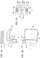
- the light source module 52 has a light emitting device 52a and a substrate 52b supporting the light emitting device 52a.
- the light emitting device 52a is, for example, a light emitting diode (LED).
- the light emitting device 52a has a rectangular light emitting surface 52af.
- the substrate 52b is, for example, a thermally conductive and electrically insulating substrate made of ceramic or the like. Electrodes 52b1 are formed on the substrate 52b to supply power to the light emitting device 52a.
- the light source mounting portion 54a has a plate-like base portion 54a1 and power feeding terminals 54a3.
- the base portion 54a1 has an opening 54a2.
- Each of the power feeding terminal 54a3 has one end fixed to the base portion 54a1 and the other end extending into the opening 54a2.
- the light source module 52 is fitted into the opening 54a2, and is fixed to the base portion 54a1.
- the light source module 52 is fixed to the base portion 54a1 such that the power feeding terminals 54a3 are connected to the electrodes 52b1 of the light source module 52.
- the light emitting device 52a is arranged such that the long sides 52af1 of the light emitting surface 52af extend in the vertical direction.
- the reflector 54b is configured to reflect light from the light emitting device 52a in the forward direction from the lamp.
- a reflecting surface of the reflector 54b may have a portion of a paraboloid of revolution having a focal point on or near the light emitting device 52a, as a reference.
- the reflector 54b is configured to reflect the light from the light emitting device 52a such that the long sides 52af1 of the light emitting surface 52af are projected to extend in the vertical direction of the diffused light distribution pattern. That is, the reflector 54b reflects the light from the light emitting device 52a and projects a light source image of the light emitting surface 52af in the forward direction from the vehicle such that the long sides of the projected light source image, which is rectangular, are made substantially parallel to the vertical line V.
- the light source mounting portion 54a is disposed near one end portion 54b1 of the reflector 54b. Accordingly, the light emitting device 52a is disposed near the one end portion 54b1.
- the light emitting device 52a is fixed to the light source mounting portion 54a such that the light emitting surface 52af faces outward in the vehicle width direction.
- light reflected by the one end portion 54b1 of the reflector 54b and light reflected by the other end portion 54b2 of the reflector 54b intersect each other. More specifically, as shown in Fig. 3 , light rays A reflected by the one end portion 54b1 and light rays B reflected by the other end portion 54b2 intersects each other.
- the lamp unit 50 is arranged such that the one end portion 54b1 of the reflector 54b is the inner side portion of the reflector 54b in the vehicle width direction and the other end portion 54b2 is the outer side portion of the reflector 54b in the vehicle width direction. Accordingly, the light reflected by the one end portion 54b1 travels more toward the outer side in the vehicle width direction than the light reflected by the other end portion 54b2. The light reflected by the one end portion 54b1 travels toward the outer side in the vehicle width direction in front of the vehicle so as to form a portion of a diffused light distribution pattern P1 on the outer side in the vehicle width direction. On the other hand, the light reflected by the other end portion 54b2 travels toward the central side in the vehicle width direction in front of the vehicle so as to form a portion of the diffused light distribution pattern P1 on the central side in the vehicle width direction.
- the reflector 54b is configured such that light is reflected more toward the outer side in the vehicle width direction as the light is reflected at a position closer to the one end portion 54b1. That is, the direction in which the light from the light emitting device 52a is reflected by the reflector 54b varies continuously from the outer side to the inner side in the vehicle width direction as the reflection position is shifted from the one end portion 54b1 to the other end portion 54b2.
- the light reflected by the one end portion 54b1 of the reflector 54b and the light reflected by the other end portion 54b2 intersect each other and are irradiated in the forward direction of the lamp.
- the width of the path the light traveling forward from the reflector 54b decreases toward a region where the light reflected by the one end portion 54b1 and the light reflected by the other end portion 54b2 intersect each other, and then increases as it goes further forward after the intersection.
- a light emitting device is disposed at the laterally center position with respect to a reflector.
- the reflector is configured such that, in the top view, a portion of the reflecting surface located on the inner side in the vehicle width direction reflects the light from the light emitting device toward the inner side in the vehicle width direction, and a portion of reflecting surface located on the outer side in the vehicle width direction reflects the light from the light emitting device toward the outer side in the vehicle width direction. Accordingly, the opening of the extension member 6 for the lamp unit for forming a diffused light distribution pattern is required to be larger than the reflector in the font view.
- the opening 6a of the extension member 6 that corresponds to the lamp unit 50 is disposed near the region where the light reflected by the one end portion 54b1 and the light reflected by the other end portion 54b2 intersect each other, so that the size of the opening 6a (i.e., the width L of the opening 6a) can be reduced as compared with the conventional structure.
- the size of the opening 6a i.e., the width L of the opening 6a
- increase in the size of the vehicle lamp 1 due to addition of the lamp unit 50 for forming a diffused light distribution pattern can be suppressed, as compared with the conventional structure.
- FIGs. 4A and 4B illustrate light distribution patterns formed on a virtual vertical screen disposed in front of the lamp, i.e., at a position 10 m ahead the lamp.
- One lateral side of the diffused light distribution pattern P1 is near the vertical line V, i.e., near the center in the vehicle width direction.
- the diffused light distribution pattern P1 extends more laterally outward than a low-beam light distribution pattern Lo toward the other lateral side of the diffused light distribution pattern P1.
- the vertical width of the diffused light distribution pattern P1 is larger on the other lateral side than on the one lateral side.
- a diffused light distribution pattern P2 formed by the right headlamp has a shape bilaterally symmetrical to the diffused light distribution pattern P1 formed by the left headlamp.
- the diffused light distribution pattern P1 and the diffused light distribution pattern P2 will be collectively referred to as a diffused light distribution pattern P.
- the diffused light distribution pattern P1 and the diffused light distribution pattern P2 extend more laterally outward than the low-beam light distribution pattern Lo in the vehicle width direction in a region right in front of the vehicle. Accordingly, as shown in Fig. 5C , when the diffused light distribution patterns P1 and P2 are formed additionally to the low-beam light distribution pattern Lo, driver's field of view in a horizontally outer area near the vehicle can be improved as compared with that in the case where only the low-beam light distribution pattern Lo is formed.
- a light emitting device is disposed in the horizontally central portion of a reflector such that long sides of a light emitting surface extend in parallel to a horizontal line H, so that light from the light emitting device is reflected such that the long sides extend in the horizontal direction of the diffused light distribution pattern.
- the light from the light emitting device is diffused vertically and horizontally so that the laterally long light source images of the light emitting surface are laterally and vertically distributed to thereby form the diffused light distribution pattern.
- the light emitting device 52a is disposed such that the long sides 52af1 of the light emitting surface 52af are parallel to the vertical line V, and the light of the light emitting device 52a is reflected such that the long sides 52afl are projected to extend in the vertical direction of the diffused light distribution pattern P. That is, in the lamp unit 50, the vertical direction in the diffused light distribution pattern P in which the vertical length is shorter than the horizontal length is associated with the long sides 52af1 of the light emitting surface 52af. Accordingly, the amount of the light of the light emitting device 52a diffused vertically can be reduced as compared with the conventional structure. It is therefore possible to reduce the vertical width of the reflector 54b.
- a light source image projected by a reflector becomes smaller as the distance between a light emitting device and the reflector increases. Accordingly, with the conventional structure in which a light emitting device is disposed in at a laterally center position with respect to a reflector, a light source image projected by each of opposite horizontal end portions of the reflector becomes smaller than a light source image projected by the horizontally central portion of the reflector.
- a diffused light distribution pattern formed by the conventional structure has a shape in which the vertical width of each of the opposite horizontal end portions is smaller than the vertical width of the horizontally central portion. Therefore, a laterally outer region near the vehicle cannot be irradiated with sufficient light.
- the vertical width of the diffused light distribution pattern as a whole is increased, the horizontally outer area near the vehicle can be irradiated with light. On that occasion, however, the vertical width of the horizontally central portion becomes further larger.
- a vertically low area in the horizontally central portion is an area hidden by the body of the vehicle and located in the dead angle in view from the driver. Thus, an area uselessly irradiated with light increases.
- the reflector 54b is designed so that light is reflected outward in the vehicle width direction by the one end portion 54b1 which is close to the light emitting device 52a, and reflected to the central side in the vehicle width direction by the other end portion 54b2 which is distant from the light emitting device 52a.
- the diffused light distribution pattern P formed by the lamp unit 50 has a shape in which the vertical width on the horizontally outer side is larger than the vertical width in the horizontally central portion, so that the horizontally outer area near the vehicle per se can be irradiated with sufficient light. Accordingly, the diffused light distribution pattern P in which the vertical width on the horizontally outer side is larger can be formed without increasing the vertical width in the horizontally central portion.
- the direction in which the light from the light emitting device 52a is reflected by the reflector 54b varies continuously from the outer side to the inner side in the vehicle width direction as the reflection position is shifted from the one end portion 54b1 to the other end portion 54b2. Accordingly, in the diffused light distribution pattern P, the vertical width increases continuously from the horizontally central portion to the horizontally outer side.
- the lamp unit 50 may be configured to form a diffused light distribution pattern and an additional light distribution pattern.
- Fig. 7 illustrates the light distribution patterns formed on a virtual vertical screen disposed in front of the lamp, e.g., at a position 10 m ahead of the lamp.
- the lamp unit 50 is configured so that light from the light emitting device 52a (light rays C in Fig. 6 ) can be radiated directly forward of the lamp. That is, the positional relation between the light emitting device 52a and the reflector 54b is determined so that a part of the light from the light emitting device 52a is not reflected by the reflector 54b but radiated to the outside of the vehicle lamp 1.
- An additional light distribution pattern P3 is formed by the light rays C radiated directly from the light emitting device 52a.
- the additional light distribution pattern P3 is formed more laterally outward in the vehicle width direction than the diffused light distribution pattern P1.
- the additional light distribution pattern P3 formed by the right headlamp has a shape bilaterally symmetrical to the additional light distribution pattern P3 formed by the left headlamp.
- the additional light distribution patterns P3 are formed in bilaterally symmetric positions. Since the additional light distribution patterns P3 are formed thus, driver's visual recognition in more outer areas in the vehicle width direction than the area irradiated with light in the diffused light distribution pattern P can be improved.
- rectangular is not limited to have a shape a rectangle, but also includes a shape resembling a rectangle to the extent that the object of the present invention can be achieved.
- the phrase "in the vertical direction” does not necessarily mean that it is parallel to the vertical line V, and may be inclined with respect to the vertical line V, e.g., at an angle of ⁇ 15°, to the extent that the object of the present invention can be achieved.
- the long sides 52af1 of the light emitting surface 52af are projected to extend in the vertical direction of the diffused light distribution pattern P" does not necessarily mean that the long sides 52af1 are parallel to the vertical line V, and the long sides 52af1 may be inclined with respect to the vertical line V, e.g., at an angle of ⁇ 15°, to the extent that the object of the present invention can be achieved.
- the light emitting device 52a having the rectangular light emitting surface 52af is disposed such that the long sides 52af1 of the light emitting surface 52af extend in the vertical direction.
- the reflector 54b reflects light from the light emitting device 52a such that the long sides 52af1 of the light emitting surface 52af are projected to extend in the vertical direction of the diffused light distribution pattern P, and such that, in the top view of the lamp unit 50, a part of the light reflected by the one end portion 54b1 of the reflector 54b and another part of the light reflected by the other end portion 54b2 of the reflector 54b intersect each other.
- the vertical direction in the diffused light distribution pattern P which is long horizontally and short vertically is associated with the long sides 52afl of the light emitting surface 52af, so that the amount of light of the light emitting device 52a diffused vertically can be reduced in comparison with that in the conventional structure in which long sides of a light emitting surface are associated with the horizontal direction of a diffused light distribution pattern. It is therefore possible to reduce the vertical width of the reflector 54b. As a result, the size of the lamp unit 50 can be reduced so that increase in the size of the vehicle lamp 1 due to addition of the lamp unit 50 for forming a diffused light distribution pattern can be suppressed.
- the size of the opening 6a of the extension member 6 that corresponds to the lamp unit 50 can be reduced as compared with a conventional structure.
- increase in the size of the vehicle lamp 1 due to addition of the lamp unit 50 for forming a diffused light distribution pattern can be suppressed.
- the lamp unit 50 for forming a diffused light distribution pattern can be disposed in a region in which the opening 6a cannot be formed largely. It is therefore possible to enhance the degree of freedom in the design of the vehicle lamp 1.
- the lamp unit 10 for forming the low-beam light distribution pattern and the lamp unit 30 for forming the high-beam light distribution pattern are provided in the vehicle lamp 1.
- the vehicle lamp 1 may include only one of the lamp units 10, 30, or may not include the lamp units 10, 30.
- a lamp unit capable of forming both the low-beam light distribution pattern and the high-beam light distribution pattern may be provided in the vehicle lamp 1.
Landscapes
- Engineering & Computer Science (AREA)
- Physics & Mathematics (AREA)
- General Engineering & Computer Science (AREA)
- Mechanical Engineering (AREA)
- Microelectronics & Electronic Packaging (AREA)
- Optics & Photonics (AREA)
- Geometry (AREA)
- Non-Portable Lighting Devices Or Systems Thereof (AREA)
Claims (6)
- Fahrzeuglampe (1), umfassend:eine lichtemittierende Vorrichtung (52a) mit einer rechteckigen lichtemittierenden Fläche (52af),einen Reflektor (54b), der dazu konfiguriert ist, Licht von der lichtemittierenden Vorrichtung (52a) in einer Vorwärtsrichtung der Fahrzeuglampe (1) zu reflektieren, um ein horizontal gestreutes Lichtverteilungsmuster (P1, P2) zu bilden, so dass, in einer Draufsicht der Fahrzeuglampe (1), ein Teil (A) des von einem Endabschnitt (54b1) des Reflektors (54b) reflektierten Lichts und ein anderer Teil (B) des von einem anderen Endabschnitt (54b2) des Reflektors (54b) reflektierten Lichts einander schneiden,dadurch gekennzeichnet, dass die lichtemittierende Vorrichtung (52a) derart angeordnet ist, dass sich die langen Seiten (52af1) der lichtemittierenden Fläche (52af) in einer vertikalen Richtung erstrecken, und der Reflektor (54b) dazu konfiguriert ist, Licht von der lichtemittierenden Vorrichtung (52a) derart zu reflektieren, dass die langen Seiten (52af1) der lichtemittierenden Fläche (52af) projiziert werden, um sich in einer vertikalen Richtung (V) des horizontal gestreuten Lichtverteilungsmusters (P1, P2) zu erstrecken.
- Fahrzeuglampe (1) nach Anspruch 1, wobei ein Abstand von der lichtemittierenden Vorrichtung (52a) zu dem einen Endabschnitt (54b1) des Reflektors (54b) kürzer ist als ein Abstand von der lichtemittierenden Vorrichtung (52a) zu dem anderen Endabschnitt (54b2) des Reflektors (54b), und
der eine Endabschnitt (54b1) des Reflektors (54b) den Teil (A) des Lichts zu einer Außenseite in einer Fahrzeugbreitenrichtung reflektiert und der andere Endabschnitt (54b2) des Reflektors (54b) den anderen Teil (B) des Lichts zu einer zentralen Seite in der Fahrzeugbreitenrichtung reflektiert. - Fahrzeuglampe (1) nach Anspruch 1 oder 2, wobei die lichtemittierende Vorrichtung (52a) und der Reflektor (54b) so angeordnet sind, dass direktes Licht (C) von der lichtemittierenden Vorrichtung (52a) ein anderes Lichtverteilungsmuster (P3) bildet, das sich in der Fahrzeugbreitenrichtung mehr seitlich nach außen erstreckt als das horizontal gestreute Lichtverteilungsmuster (P1, P2).
- Fahrzeuglampe (1) nach einem der vorhergehenden Ansprüche, wobei die Lichtemissionsvorrichtung (52a) derart angeordnet ist, dass die lichtemittierende Fläche (52af) in der Fahrzeugbreitenrichtung nach außen weist.
- Fahrzeuglampe (1) nach einem der vorhergehenden Ansprüche, ferner umfassend:einen Lampenkörper (2) mit einer vorderen Öffnung,eine transparente Abdeckung (4), die an dem Lampenkörper (2) angebracht ist, um die vordere Öffnung abzudecken, undein Verlängerungselement (6), das in einer Lampenkammer (3) untergebracht ist, die durch den Lampenkörper (2) und die transparente Abdeckung (4) gebildet ist,wobei das Verlängerungselement (6) eine Öffnung (6a) in einem Bereich aufweist, in dem der Teil (A) des von dem einen Endabschnitt (54b1) des Reflektors (54b) reflektierten Lichts und der andere Teil (B) des von dem anderen Endabschnitt (54b2) des Reflektors (54b) reflektierten Lichts einander schneiden.
- Fahrzeuglampe (1) nach Anspruch 5, ferner umfassend eine Lampeneinheit (10), die eingerichtet ist, um ein Abblendlicht-Lichtverteilungsmuster (Lo) zu bilden, wobei das horizontal gestreute Lichtverteilungsmuster (P1, P2) einen breiteren seitlichen Diffusionswinkel aufweist als das Abblendlichtverteilungsmuster (Lo).
Applications Claiming Priority (1)
| Application Number | Priority Date | Filing Date | Title |
|---|---|---|---|
| JP2011023861A JP5711558B2 (ja) | 2011-02-07 | 2011-02-07 | 光学ユニットおよび車両用灯具 |
Publications (3)
| Publication Number | Publication Date |
|---|---|
| EP2484553A2 EP2484553A2 (de) | 2012-08-08 |
| EP2484553A3 EP2484553A3 (de) | 2012-12-05 |
| EP2484553B1 true EP2484553B1 (de) | 2018-07-04 |
Family
ID=45560821
Family Applications (1)
| Application Number | Title | Priority Date | Filing Date |
|---|---|---|---|
| EP12154292.2A Not-in-force EP2484553B1 (de) | 2011-02-07 | 2012-02-07 | Fahrzeuglampe und optische Einheit dafür |
Country Status (2)
| Country | Link |
|---|---|
| EP (1) | EP2484553B1 (de) |
| JP (1) | JP5711558B2 (de) |
Families Citing this family (6)
| Publication number | Priority date | Publication date | Assignee | Title |
|---|---|---|---|---|
| JP5733129B2 (ja) | 2011-09-20 | 2015-06-10 | 市光工業株式会社 | 車両用灯具 |
| JP6107038B2 (ja) * | 2012-10-02 | 2017-04-05 | 市光工業株式会社 | 車両用前照灯および車両用前照灯装置 |
| DE102013102835B4 (de) * | 2013-03-20 | 2022-12-29 | HELLA GmbH & Co. KGaA | Beleuchtungsvorrichtung |
| JP2019175621A (ja) * | 2018-03-27 | 2019-10-10 | いすゞ自動車株式会社 | 照明装置および車両 |
| JP7177802B2 (ja) * | 2020-06-15 | 2022-11-24 | スタンレー電気株式会社 | 車両用灯具 |
| JP7426306B2 (ja) | 2020-07-27 | 2024-02-01 | スタンレー電気株式会社 | 車両用灯具 |
Family Cites Families (16)
| Publication number | Priority date | Publication date | Assignee | Title |
|---|---|---|---|---|
| JP3722018B2 (ja) * | 2001-06-27 | 2005-11-30 | 豊田合成株式会社 | 遮光反射型発光ダイオード |
| EP1276157A3 (de) * | 2001-06-27 | 2005-02-09 | Toyoda Gosei Co., Ltd. | Abgeschirmte reflektierende lichtemittierende Vorrichtung |
| JP3966017B2 (ja) * | 2002-02-26 | 2007-08-29 | 市光工業株式会社 | 車両用灯具 |
| JP4103440B2 (ja) * | 2002-04-24 | 2008-06-18 | 市光工業株式会社 | 車両用灯具 |
| DE10236825A1 (de) * | 2002-08-10 | 2004-04-01 | Hella Kg Hueck & Co. | Beleuchtungseinheit für Kraftfahrzeuge |
| JP4115921B2 (ja) * | 2003-11-04 | 2008-07-09 | 株式会社小糸製作所 | 車両用前照灯 |
| JP4392786B2 (ja) * | 2003-11-04 | 2010-01-06 | 株式会社小糸製作所 | 車両用前照灯 |
| US7658513B2 (en) * | 2005-03-03 | 2010-02-09 | Dialight Corporation | LED illumination device with a highly uniform illumination pattern |
| WO2006126114A1 (en) * | 2005-05-25 | 2006-11-30 | Koninklijke Philips Electronics N.V. | Illumination system, shelf-lighting system and wall-washer lighting system |
| US7410282B2 (en) * | 2005-10-25 | 2008-08-12 | Visteon Global Technologies, Inc. | Bi-functional headlight module |
| JP2008226707A (ja) | 2007-03-14 | 2008-09-25 | Koito Mfg Co Ltd | 車両用灯具 |
| JP4745272B2 (ja) | 2007-03-14 | 2011-08-10 | 株式会社小糸製作所 | 車両用灯具 |
| JP4926771B2 (ja) * | 2007-03-15 | 2012-05-09 | 株式会社小糸製作所 | 車両用灯具ユニット |
| JP4864834B2 (ja) * | 2007-08-21 | 2012-02-01 | 株式会社小糸製作所 | 車両用コーナリングランプ |
| JP5070653B2 (ja) * | 2008-03-28 | 2012-11-14 | スタンレー電気株式会社 | 半導体光源を用いた車両用反射型ヘッドランプユニット |
| DE102008034376B4 (de) * | 2008-07-23 | 2022-03-17 | HELLA GmbH & Co. KGaA | Signalleuchte für Fahrzeuge |
-
2011
- 2011-02-07 JP JP2011023861A patent/JP5711558B2/ja not_active Expired - Fee Related
-
2012
- 2012-02-07 EP EP12154292.2A patent/EP2484553B1/de not_active Not-in-force
Non-Patent Citations (1)
| Title |
|---|
| None * |
Also Published As
| Publication number | Publication date |
|---|---|
| EP2484553A2 (de) | 2012-08-08 |
| JP2012164515A (ja) | 2012-08-30 |
| JP5711558B2 (ja) | 2015-05-07 |
| EP2484553A3 (de) | 2012-12-05 |
Similar Documents
| Publication | Publication Date | Title |
|---|---|---|
| US8511874B2 (en) | Vehicle lamp | |
| US9212799B2 (en) | Lamp unit | |
| US7237935B2 (en) | Light source module and vehicular lamp | |
| EP2187115A2 (de) | Fahrzeuglampe | |
| US8864351B2 (en) | Vehicle headlamp | |
| US8678629B2 (en) | Lamp unit for vehicular headlamp | |
| EP2366940B1 (de) | Projektionsschweinwerfer für Motorräder | |
| EP2484553B1 (de) | Fahrzeuglampe und optische Einheit dafür | |
| US9539931B2 (en) | Automotive lamp | |
| EP2075500B1 (de) | Fahrzeugscheinwerfer | |
| US8256942B2 (en) | Vehicle headlamp | |
| JP2013258059A (ja) | 灯具ユニットおよび投影レンズ | |
| US9528675B2 (en) | Automotive lamp | |
| CN108692270B (zh) | 车灯装置 | |
| JP5468876B2 (ja) | 光学ユニット | |
| JP5591097B2 (ja) | 光学ユニット | |
| JP7285362B2 (ja) | 車両用前照灯 | |
| US11022263B2 (en) | Headlight for vehicle | |
| JP5666934B2 (ja) | 光学ユニットおよび車両用灯具 | |
| WO2023162906A1 (ja) | 車両用灯具 | |
| JP2011238524A (ja) | 車両用前照灯 | |
| EP2479063A2 (de) | Optische Einheit und Fahrzeuglampe |
Legal Events
| Date | Code | Title | Description |
|---|---|---|---|
| PUAI | Public reference made under article 153(3) epc to a published international application that has entered the european phase |
Free format text: ORIGINAL CODE: 0009012 |
|
| 17P | Request for examination filed |
Effective date: 20120207 |
|
| AK | Designated contracting states |
Kind code of ref document: A2 Designated state(s): AL AT BE BG CH CY CZ DE DK EE ES FI FR GB GR HR HU IE IS IT LI LT LU LV MC MK MT NL NO PL PT RO RS SE SI SK SM TR |
|
| AX | Request for extension of the european patent |
Extension state: BA ME |
|
| PUAL | Search report despatched |
Free format text: ORIGINAL CODE: 0009013 |
|
| AK | Designated contracting states |
Kind code of ref document: A3 Designated state(s): AL AT BE BG CH CY CZ DE DK EE ES FI FR GB GR HR HU IE IS IT LI LT LU LV MC MK MT NL NO PL PT RO RS SE SI SK SM TR |
|
| AX | Request for extension of the european patent |
Extension state: BA ME |
|
| RIC1 | Information provided on ipc code assigned before grant |
Ipc: F21V 7/00 20060101ALI20121031BHEP Ipc: B60Q 1/18 20060101ALI20121031BHEP Ipc: B60Q 1/00 20060101AFI20121031BHEP Ipc: F21S 8/10 20060101ALI20121031BHEP |
|
| STAA | Information on the status of an ep patent application or granted ep patent |
Free format text: STATUS: EXAMINATION IS IN PROGRESS |
|
| 17Q | First examination report despatched |
Effective date: 20170214 |
|
| GRAP | Despatch of communication of intention to grant a patent |
Free format text: ORIGINAL CODE: EPIDOSNIGR1 |
|
| STAA | Information on the status of an ep patent application or granted ep patent |
Free format text: STATUS: GRANT OF PATENT IS INTENDED |
|
| RIC1 | Information provided on ipc code assigned before grant |
Ipc: B60Q 1/18 20060101ALI20180108BHEP Ipc: F21V 7/00 20060101ALI20180108BHEP Ipc: F21S 41/32 20180101ALI20180108BHEP Ipc: F21S 41/147 20180101ALI20180108BHEP Ipc: B60Q 1/00 20060101AFI20180108BHEP |
|
| INTG | Intention to grant announced |
Effective date: 20180126 |
|
| GRAS | Grant fee paid |
Free format text: ORIGINAL CODE: EPIDOSNIGR3 |
|
| GRAA | (expected) grant |
Free format text: ORIGINAL CODE: 0009210 |
|
| STAA | Information on the status of an ep patent application or granted ep patent |
Free format text: STATUS: THE PATENT HAS BEEN GRANTED |
|
| AK | Designated contracting states |
Kind code of ref document: B1 Designated state(s): AL AT BE BG CH CY CZ DE DK EE ES FI FR GB GR HR HU IE IS IT LI LT LU LV MC MK MT NL NO PL PT RO RS SE SI SK SM TR |
|
| REG | Reference to a national code |
Ref country code: GB Ref legal event code: FG4D |
|
| REG | Reference to a national code |
Ref country code: CH Ref legal event code: EP |
|
| REG | Reference to a national code |
Ref country code: AT Ref legal event code: REF Ref document number: 1014149 Country of ref document: AT Kind code of ref document: T Effective date: 20180715 |
|
| REG | Reference to a national code |
Ref country code: IE Ref legal event code: FG4D |
|
| REG | Reference to a national code |
Ref country code: DE Ref legal event code: R096 Ref document number: 602012047986 Country of ref document: DE |
|
| REG | Reference to a national code |
Ref country code: NL Ref legal event code: MP Effective date: 20180704 |
|
| REG | Reference to a national code |
Ref country code: LT Ref legal event code: MG4D |
|
| REG | Reference to a national code |
Ref country code: AT Ref legal event code: MK05 Ref document number: 1014149 Country of ref document: AT Kind code of ref document: T Effective date: 20180704 |
|
| PG25 | Lapsed in a contracting state [announced via postgrant information from national office to epo] |
Ref country code: NL Free format text: LAPSE BECAUSE OF FAILURE TO SUBMIT A TRANSLATION OF THE DESCRIPTION OR TO PAY THE FEE WITHIN THE PRESCRIBED TIME-LIMIT Effective date: 20180704 |
|
| PG25 | Lapsed in a contracting state [announced via postgrant information from national office to epo] |
Ref country code: CZ Free format text: LAPSE BECAUSE OF FAILURE TO SUBMIT A TRANSLATION OF THE DESCRIPTION OR TO PAY THE FEE WITHIN THE PRESCRIBED TIME-LIMIT Effective date: 20180704 Ref country code: GR Free format text: LAPSE BECAUSE OF FAILURE TO SUBMIT A TRANSLATION OF THE DESCRIPTION OR TO PAY THE FEE WITHIN THE PRESCRIBED TIME-LIMIT Effective date: 20181005 Ref country code: BG Free format text: LAPSE BECAUSE OF FAILURE TO SUBMIT A TRANSLATION OF THE DESCRIPTION OR TO PAY THE FEE WITHIN THE PRESCRIBED TIME-LIMIT Effective date: 20181004 Ref country code: NO Free format text: LAPSE BECAUSE OF FAILURE TO SUBMIT A TRANSLATION OF THE DESCRIPTION OR TO PAY THE FEE WITHIN THE PRESCRIBED TIME-LIMIT Effective date: 20181004 Ref country code: IS Free format text: LAPSE BECAUSE OF FAILURE TO SUBMIT A TRANSLATION OF THE DESCRIPTION OR TO PAY THE FEE WITHIN THE PRESCRIBED TIME-LIMIT Effective date: 20181104 Ref country code: AT Free format text: LAPSE BECAUSE OF FAILURE TO SUBMIT A TRANSLATION OF THE DESCRIPTION OR TO PAY THE FEE WITHIN THE PRESCRIBED TIME-LIMIT Effective date: 20180704 Ref country code: PL Free format text: LAPSE BECAUSE OF FAILURE TO SUBMIT A TRANSLATION OF THE DESCRIPTION OR TO PAY THE FEE WITHIN THE PRESCRIBED TIME-LIMIT Effective date: 20180704 Ref country code: FI Free format text: LAPSE BECAUSE OF FAILURE TO SUBMIT A TRANSLATION OF THE DESCRIPTION OR TO PAY THE FEE WITHIN THE PRESCRIBED TIME-LIMIT Effective date: 20180704 Ref country code: RS Free format text: LAPSE BECAUSE OF FAILURE TO SUBMIT A TRANSLATION OF THE DESCRIPTION OR TO PAY THE FEE WITHIN THE PRESCRIBED TIME-LIMIT Effective date: 20180704 Ref country code: LT Free format text: LAPSE BECAUSE OF FAILURE TO SUBMIT A TRANSLATION OF THE DESCRIPTION OR TO PAY THE FEE WITHIN THE PRESCRIBED TIME-LIMIT Effective date: 20180704 Ref country code: SE Free format text: LAPSE BECAUSE OF FAILURE TO SUBMIT A TRANSLATION OF THE DESCRIPTION OR TO PAY THE FEE WITHIN THE PRESCRIBED TIME-LIMIT Effective date: 20180704 |
|
| REG | Reference to a national code |
Ref country code: CH Ref legal event code: PK Free format text: BERICHTIGUNGEN |
|
| RIC2 | Information provided on ipc code assigned after grant |
Ipc: B60Q 1/00 20060101AFI20180108BHEP Ipc: F21S 41/147 20180101ALI20180108BHEP Ipc: F21V 7/00 20060101ALI20180108BHEP Ipc: F21S 41/32 20180101ALI20180108BHEP Ipc: B60Q 1/18 20060101ALI20180108BHEP |
|
| PG25 | Lapsed in a contracting state [announced via postgrant information from national office to epo] |
Ref country code: AL Free format text: LAPSE BECAUSE OF FAILURE TO SUBMIT A TRANSLATION OF THE DESCRIPTION OR TO PAY THE FEE WITHIN THE PRESCRIBED TIME-LIMIT Effective date: 20180704 Ref country code: HR Free format text: LAPSE BECAUSE OF FAILURE TO SUBMIT A TRANSLATION OF THE DESCRIPTION OR TO PAY THE FEE WITHIN THE PRESCRIBED TIME-LIMIT Effective date: 20180704 Ref country code: LV Free format text: LAPSE BECAUSE OF FAILURE TO SUBMIT A TRANSLATION OF THE DESCRIPTION OR TO PAY THE FEE WITHIN THE PRESCRIBED TIME-LIMIT Effective date: 20180704 Ref country code: ES Free format text: LAPSE BECAUSE OF FAILURE TO SUBMIT A TRANSLATION OF THE DESCRIPTION OR TO PAY THE FEE WITHIN THE PRESCRIBED TIME-LIMIT Effective date: 20180704 |
|
| REG | Reference to a national code |
Ref country code: DE Ref legal event code: R097 Ref document number: 602012047986 Country of ref document: DE |
|
| PG25 | Lapsed in a contracting state [announced via postgrant information from national office to epo] |
Ref country code: EE Free format text: LAPSE BECAUSE OF FAILURE TO SUBMIT A TRANSLATION OF THE DESCRIPTION OR TO PAY THE FEE WITHIN THE PRESCRIBED TIME-LIMIT Effective date: 20180704 Ref country code: IT Free format text: LAPSE BECAUSE OF FAILURE TO SUBMIT A TRANSLATION OF THE DESCRIPTION OR TO PAY THE FEE WITHIN THE PRESCRIBED TIME-LIMIT Effective date: 20180704 Ref country code: RO Free format text: LAPSE BECAUSE OF FAILURE TO SUBMIT A TRANSLATION OF THE DESCRIPTION OR TO PAY THE FEE WITHIN THE PRESCRIBED TIME-LIMIT Effective date: 20180704 |
|
| PLBE | No opposition filed within time limit |
Free format text: ORIGINAL CODE: 0009261 |
|
| STAA | Information on the status of an ep patent application or granted ep patent |
Free format text: STATUS: NO OPPOSITION FILED WITHIN TIME LIMIT |
|
| PG25 | Lapsed in a contracting state [announced via postgrant information from national office to epo] |
Ref country code: SM Free format text: LAPSE BECAUSE OF FAILURE TO SUBMIT A TRANSLATION OF THE DESCRIPTION OR TO PAY THE FEE WITHIN THE PRESCRIBED TIME-LIMIT Effective date: 20180704 Ref country code: DK Free format text: LAPSE BECAUSE OF FAILURE TO SUBMIT A TRANSLATION OF THE DESCRIPTION OR TO PAY THE FEE WITHIN THE PRESCRIBED TIME-LIMIT Effective date: 20180704 Ref country code: SK Free format text: LAPSE BECAUSE OF FAILURE TO SUBMIT A TRANSLATION OF THE DESCRIPTION OR TO PAY THE FEE WITHIN THE PRESCRIBED TIME-LIMIT Effective date: 20180704 |
|
| 26N | No opposition filed |
Effective date: 20190405 |
|
| PG25 | Lapsed in a contracting state [announced via postgrant information from national office to epo] |
Ref country code: SI Free format text: LAPSE BECAUSE OF FAILURE TO SUBMIT A TRANSLATION OF THE DESCRIPTION OR TO PAY THE FEE WITHIN THE PRESCRIBED TIME-LIMIT Effective date: 20180704 |
|
| REG | Reference to a national code |
Ref country code: CH Ref legal event code: PL |
|
| GBPC | Gb: european patent ceased through non-payment of renewal fee |
Effective date: 20190207 |
|
| PG25 | Lapsed in a contracting state [announced via postgrant information from national office to epo] |
Ref country code: MC Free format text: LAPSE BECAUSE OF FAILURE TO SUBMIT A TRANSLATION OF THE DESCRIPTION OR TO PAY THE FEE WITHIN THE PRESCRIBED TIME-LIMIT Effective date: 20180704 Ref country code: LU Free format text: LAPSE BECAUSE OF NON-PAYMENT OF DUE FEES Effective date: 20190207 |
|
| REG | Reference to a national code |
Ref country code: BE Ref legal event code: MM Effective date: 20190228 |
|
| REG | Reference to a national code |
Ref country code: IE Ref legal event code: MM4A |
|
| PG25 | Lapsed in a contracting state [announced via postgrant information from national office to epo] |
Ref country code: LI Free format text: LAPSE BECAUSE OF NON-PAYMENT OF DUE FEES Effective date: 20190228 Ref country code: CH Free format text: LAPSE BECAUSE OF NON-PAYMENT OF DUE FEES Effective date: 20190228 |
|
| PG25 | Lapsed in a contracting state [announced via postgrant information from national office to epo] |
Ref country code: IE Free format text: LAPSE BECAUSE OF NON-PAYMENT OF DUE FEES Effective date: 20190207 Ref country code: GB Free format text: LAPSE BECAUSE OF NON-PAYMENT OF DUE FEES Effective date: 20190207 |
|
| PG25 | Lapsed in a contracting state [announced via postgrant information from national office to epo] |
Ref country code: BE Free format text: LAPSE BECAUSE OF NON-PAYMENT OF DUE FEES Effective date: 20190228 |
|
| PG25 | Lapsed in a contracting state [announced via postgrant information from national office to epo] |
Ref country code: TR Free format text: LAPSE BECAUSE OF FAILURE TO SUBMIT A TRANSLATION OF THE DESCRIPTION OR TO PAY THE FEE WITHIN THE PRESCRIBED TIME-LIMIT Effective date: 20180704 |
|
| PGFP | Annual fee paid to national office [announced via postgrant information from national office to epo] |
Ref country code: DE Payment date: 20200129 Year of fee payment: 9 |
|
| PG25 | Lapsed in a contracting state [announced via postgrant information from national office to epo] |
Ref country code: PT Free format text: LAPSE BECAUSE OF FAILURE TO SUBMIT A TRANSLATION OF THE DESCRIPTION OR TO PAY THE FEE WITHIN THE PRESCRIBED TIME-LIMIT Effective date: 20181105 Ref country code: MT Free format text: LAPSE BECAUSE OF NON-PAYMENT OF DUE FEES Effective date: 20190207 |
|
| PGFP | Annual fee paid to national office [announced via postgrant information from national office to epo] |
Ref country code: FR Payment date: 20200113 Year of fee payment: 9 |
|
| PG25 | Lapsed in a contracting state [announced via postgrant information from national office to epo] |
Ref country code: CY Free format text: LAPSE BECAUSE OF FAILURE TO SUBMIT A TRANSLATION OF THE DESCRIPTION OR TO PAY THE FEE WITHIN THE PRESCRIBED TIME-LIMIT Effective date: 20180704 |
|
| PG25 | Lapsed in a contracting state [announced via postgrant information from national office to epo] |
Ref country code: HU Free format text: LAPSE BECAUSE OF FAILURE TO SUBMIT A TRANSLATION OF THE DESCRIPTION OR TO PAY THE FEE WITHIN THE PRESCRIBED TIME-LIMIT; INVALID AB INITIO Effective date: 20120207 |
|
| REG | Reference to a national code |
Ref country code: DE Ref legal event code: R119 Ref document number: 602012047986 Country of ref document: DE |
|
| PG25 | Lapsed in a contracting state [announced via postgrant information from national office to epo] |
Ref country code: DE Free format text: LAPSE BECAUSE OF NON-PAYMENT OF DUE FEES Effective date: 20210901 Ref country code: FR Free format text: LAPSE BECAUSE OF NON-PAYMENT OF DUE FEES Effective date: 20210228 |
|
| PG25 | Lapsed in a contracting state [announced via postgrant information from national office to epo] |
Ref country code: MK Free format text: LAPSE BECAUSE OF FAILURE TO SUBMIT A TRANSLATION OF THE DESCRIPTION OR TO PAY THE FEE WITHIN THE PRESCRIBED TIME-LIMIT Effective date: 20180704 |