EP2479063A2 - Optische Einheit und Fahrzeuglampe - Google Patents
Optische Einheit und Fahrzeuglampe Download PDFInfo
- Publication number
- EP2479063A2 EP2479063A2 EP12151080A EP12151080A EP2479063A2 EP 2479063 A2 EP2479063 A2 EP 2479063A2 EP 12151080 A EP12151080 A EP 12151080A EP 12151080 A EP12151080 A EP 12151080A EP 2479063 A2 EP2479063 A2 EP 2479063A2
- Authority
- EP
- European Patent Office
- Prior art keywords
- light
- line
- lamp
- distribution pattern
- vertical cut
- Prior art date
- Legal status (The legal status is an assumption and is not a legal conclusion. Google has not performed a legal analysis and makes no representation as to the accuracy of the status listed.)
- Withdrawn
Links
Images


Classifications
-
- B—PERFORMING OPERATIONS; TRANSPORTING
- B60—VEHICLES IN GENERAL
- B60Q—ARRANGEMENT OF SIGNALLING OR LIGHTING DEVICES, THE MOUNTING OR SUPPORTING THEREOF OR CIRCUITS THEREFOR, FOR VEHICLES IN GENERAL
- B60Q1/00—Arrangement of optical signalling or lighting devices, the mounting or supporting thereof or circuits therefor
- B60Q1/02—Arrangement of optical signalling or lighting devices, the mounting or supporting thereof or circuits therefor the devices being primarily intended to illuminate the way ahead or to illuminate other areas of way or environments
- B60Q1/04—Arrangement of optical signalling or lighting devices, the mounting or supporting thereof or circuits therefor the devices being primarily intended to illuminate the way ahead or to illuminate other areas of way or environments the devices being headlights
- B60Q1/14—Arrangement of optical signalling or lighting devices, the mounting or supporting thereof or circuits therefor the devices being primarily intended to illuminate the way ahead or to illuminate other areas of way or environments the devices being headlights having dimming means
- B60Q1/1415—Dimming circuits
- B60Q1/1423—Automatic dimming circuits, i.e. switching between high beam and low beam due to change of ambient light or light level in road traffic
- B60Q1/143—Automatic dimming circuits, i.e. switching between high beam and low beam due to change of ambient light or light level in road traffic combined with another condition, e.g. using vehicle recognition from camera images or activation of wipers
-
- B—PERFORMING OPERATIONS; TRANSPORTING
- B60—VEHICLES IN GENERAL
- B60Q—ARRANGEMENT OF SIGNALLING OR LIGHTING DEVICES, THE MOUNTING OR SUPPORTING THEREOF OR CIRCUITS THEREFOR, FOR VEHICLES IN GENERAL
- B60Q1/00—Arrangement of optical signalling or lighting devices, the mounting or supporting thereof or circuits therefor
- B60Q1/0029—Spatial arrangement
- B60Q1/0041—Spatial arrangement of several lamps in relation to each other
-
- F—MECHANICAL ENGINEERING; LIGHTING; HEATING; WEAPONS; BLASTING
- F21—LIGHTING
- F21S—NON-PORTABLE LIGHTING DEVICES; SYSTEMS THEREOF; VEHICLE LIGHTING DEVICES SPECIALLY ADAPTED FOR VEHICLE EXTERIORS
- F21S41/00—Illuminating devices specially adapted for vehicle exteriors, e.g. headlamps
- F21S41/10—Illuminating devices specially adapted for vehicle exteriors, e.g. headlamps characterised by the light source
- F21S41/14—Illuminating devices specially adapted for vehicle exteriors, e.g. headlamps characterised by the light source characterised by the type of light source
- F21S41/141—Light emitting diodes [LED]
- F21S41/147—Light emitting diodes [LED] the main emission direction of the LED being angled to the optical axis of the illuminating device
- F21S41/148—Light emitting diodes [LED] the main emission direction of the LED being angled to the optical axis of the illuminating device the main emission direction of the LED being perpendicular to the optical axis
-
- F—MECHANICAL ENGINEERING; LIGHTING; HEATING; WEAPONS; BLASTING
- F21—LIGHTING
- F21S—NON-PORTABLE LIGHTING DEVICES; SYSTEMS THEREOF; VEHICLE LIGHTING DEVICES SPECIALLY ADAPTED FOR VEHICLE EXTERIORS
- F21S41/00—Illuminating devices specially adapted for vehicle exteriors, e.g. headlamps
- F21S41/10—Illuminating devices specially adapted for vehicle exteriors, e.g. headlamps characterised by the light source
- F21S41/14—Illuminating devices specially adapted for vehicle exteriors, e.g. headlamps characterised by the light source characterised by the type of light source
- F21S41/141—Light emitting diodes [LED]
- F21S41/155—Surface emitters, e.g. organic light emitting diodes [OLED]
-
- F—MECHANICAL ENGINEERING; LIGHTING; HEATING; WEAPONS; BLASTING
- F21—LIGHTING
- F21S—NON-PORTABLE LIGHTING DEVICES; SYSTEMS THEREOF; VEHICLE LIGHTING DEVICES SPECIALLY ADAPTED FOR VEHICLE EXTERIORS
- F21S41/00—Illuminating devices specially adapted for vehicle exteriors, e.g. headlamps
- F21S41/30—Illuminating devices specially adapted for vehicle exteriors, e.g. headlamps characterised by reflectors
- F21S41/32—Optical layout thereof
- F21S41/33—Multi-surface reflectors, e.g. reflectors with facets or reflectors with portions of different curvature
- F21S41/331—Multi-surface reflectors, e.g. reflectors with facets or reflectors with portions of different curvature the reflector consisting of complete annular areas
- F21S41/333—Multi-surface reflectors, e.g. reflectors with facets or reflectors with portions of different curvature the reflector consisting of complete annular areas with discontinuity at the junction between adjacent areas
-
- B—PERFORMING OPERATIONS; TRANSPORTING
- B60—VEHICLES IN GENERAL
- B60Q—ARRANGEMENT OF SIGNALLING OR LIGHTING DEVICES, THE MOUNTING OR SUPPORTING THEREOF OR CIRCUITS THEREFOR, FOR VEHICLES IN GENERAL
- B60Q2300/00—Indexing codes for automatically adjustable headlamps or automatically dimmable headlamps
- B60Q2300/05—Special features for controlling or switching of the light beam
- B60Q2300/056—Special anti-blinding beams, e.g. a standard beam is chopped or moved in order not to blind
-
- B—PERFORMING OPERATIONS; TRANSPORTING
- B60—VEHICLES IN GENERAL
- B60Q—ARRANGEMENT OF SIGNALLING OR LIGHTING DEVICES, THE MOUNTING OR SUPPORTING THEREOF OR CIRCUITS THEREFOR, FOR VEHICLES IN GENERAL
- B60Q2300/00—Indexing codes for automatically adjustable headlamps or automatically dimmable headlamps
- B60Q2300/40—Indexing codes relating to other road users or special conditions
- B60Q2300/42—Indexing codes relating to other road users or special conditions oncoming vehicle
Definitions
- the present invention relates to an optical unit and a vehicular lamp equipped with the optical unit.
- Patent Documents 1 and 2 disclose so-called parabolic vehicular lamps each equipped with a light-emitting element and a parabola optical system reflector that reflects light from the light-emitting element to the front of the lamp. These vehicular lamps are vehicular lamps for forming a low-beam distribution pattern.
- a vehicular lamp that is used as a vehicular headlamp is able to switch a light distribution pattern between a low-beam distribution pattern and a high-beam distribution pattern.
- a vehicular lamp that is structured so as to be able to form, in addition to a low-beam distribution pattern and a high-beam distribution pattern, a special light distribution pattern that has a shape intermediate between the low-beam distribution pattern and the high-beam distribution pattern, and that is able to execute ADB (Adaptive Driving Beam) control for forming a light distribution pattern on the basis of presence or absence of other vehicles in an area ahead of the host vehicle.
- ADB Adaptive Driving Beam
- the above-described special light distribution pattern there is a so-called one-sided high-beam distribution pattern which includes an area above a cut-off line of the low-beam distribution pattern and on the left side or right side of a vertical line.
- the one-sided high-beam distribution pattern has a vertical cut-off line that extends in the vertical direction.
- the vertical cut-off line is the boundary between a light radiation area and a light-blocking area that are located above the cut-off line of the low-beam distribution pattern and that are next to each other in the horizontal direction.
- the above-described ADB control is supposed to be executed in a so-called projector-type vehicular lamp because a special light distribution pattern is formed relatively easily with the projector-type vehicular lamp.
- the inventors conceived of the idea of executing the ADB control in a parabolic vehicular lamp.
- the cost of a vehicular lamp is made lower than when a projector-type vehicular lamp is used.
- the inventors then realized that a conventional parabolic vehicular lamp has room for improvement in terms of forming a clear vertical cut-off line.
- the present invention has been made based on such realization achieved by the inventors, and it is an object of the present invention to provide art for forming a light distribution pattern that has a clear cut-off line with the use of a parabolic vehicular lamp.
- an aspect of the invention provides a vehicular lamp for forming a light distribution pattern that has a vertical cut-off line, characterized by comprising: a light-emitting element that has a generally rectangular light-emitting surface; and a parabola optical system reflector that reflects light from the light-emitting element to a front of the lamp, wherein the vehicular lamp is configured to form the vertical cut-off line with the use of a long side of the light-emitting surface.
- an angle formed between the long side of the light-emitting surface and the vertical line may be within a range of ⁇ 15° with respect to the vertical line.
- Another aspect of the invention relates to an optical unit that is used in a vehicular lamp for forming a light distribution pattern that has a vertical cut-off line, characterized by comprising: an element mounting portion to which a light-emitting element that has a generally rectangular light-emitting surface is fixed; and a parabola optical system reflector that reflects light from the light-emitting element fixed to the element mounting portion to a front of the lamp, wherein the optical unit is configured to form the vertical cut-off line with the use of a long side of the light-emitting surface of the light-emitting element fixed to the element mounting portion.
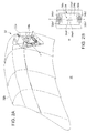
- FIG. 1 is a schematic horizontal cross-sectional view of a vehicular lamp according to a first embodiment.
- FIG. 2A is a schematic perspective view of a lamp unit that forms a vertical cut-off line forming portion pattern.
- FIG. 2B is a schematic partial plan view of the vicinity of a light-emitting element in the lamp unit that forms the vertical cut-off line forming portion pattern.
- a vehicular lamp 1 according to the present embodiment is a vehicular headlamp device that has a pair of headlamp units respectively disposed on the left and right of the vehicle front.
- the paired headlamp units have substantially the identical structure except that they have bilaterally-symmetric structures. Therefore, FIG. 1 shows the structure of the headlamp unit disposed on the left side of the vehicle front as the vehicular lamp 1.
- the vehicular lamp 1 includes a lamp body 2 which has an opening on the vehicle front side, and a translucent cover 4 attached to cover the opening of the lamp body 2.
- the translucent cover 4 is made of resin, glasses, or the like that has translucency.
- a lamp unit 10 and a lamp unit 30 are accommodated inside a lamp chamber 3 which is defined by the lamp body 2 and the translucent cover 4.
- the lamp unit 10 and the lamp unit 30 are attached to the lamp body 2 via respective supporting members (not shown), and accommodated in the lamp chamber 3. Because the structure for attaching the lamp units 10 and 30 to the lamp body 2 is known, detailed description thereof will be omitted.
- an extension member 6 which has openings in areas where the lamp units 10 and 30 are provided is accommodated.
- the extension member 6 is fixed to the lamp body 2.
- the opening of the lamp body 2 and the area between the lamp units 10 and 30 are covered by the extension member 6 when viewed from the front of the lamp.
- the lamp unit 10 is a lamp unit for forming a low-beam distribution pattern and a high-beam distribution pattern.
- the lamp unit 10 is a so-called projector-type lamp unit, and has a light source bulb 12, a reflector 14, a shade 16, a lens holder 18, and a projection lens 20.
- a light source bulb 12 an incandescent lamp which has a filament, such as a halogen lamp, or a discharge lamp which is formed from an HID lamp (also called "discharge lamp”) such as a metal halide bulb may be adopted.
- HID lamp also called "discharge lamp”
- a light-emitting element such as an LED may be adopted.
- the reflector 14 is formed in a cup shape and has an insertion hole at its center.
- the light source bulb 12 is inserted in the insertion hole of the reflector 14, and fixed to the reflector 14.
- a generally ellipsoidal spherical reflective surface is formed in at least part of the reflector 14, and the light source bulb 12 is disposed in the vicinity of a primary focal point of the reflective surface. In the vicinity of a secondary focal point of the reflective surface, a rear side focal point of the projection lens 20, described later, is set.
- the shade 16 is a flat plate member, and is disposed so as to be able to advance or retract with respect to an optical axis of the lamp unit 10.
- the shade 16 is disposed such that its edge portion is located in the vicinity of the secondary focal point of the reflector 14 or the rear focal point of the projection lens 20 when the shade 16 is in an advanced position with respect to the optical axis.
- the edge portion has a shape that corresponds to a cut-off line of the low-beam distribution pattern.
- the projection lens 20 is formed from a planoconvex nonspherical lens that has a convex front side surface and a flat rear side surface.
- the projection lens 20 projects a light source image formed on a rear focal plane including the rear focal point of the projection lens 20 onto a virtual vertical screen in front of the lamp, as an inverted image.
- the projection lens 20 is fixed to the front end portion of a lens holder 18.
- the lens holder 18 is fixed at its rear end portion to the front end portion of the reflector 14.
- the light emitted from the light source bulb 12 is guided, directly or after being reflected by the reflector 14, to the projection lens 20 through the shade 16.
- the shade 16 When the shade 16 is in the advanced position with respect to the optical axis of the lamp unit 10, the light heading to the projection lens 20 is partially blocked by the shade 16, whereby the low-beam distribution pattern is formed.
- the shade 16 when the shade 16 is in the retracted position with respect to the optical axis of the lamp unit 10, the high-beam distribution pattern is formed.
- the lamp unit 10 may be a so-called parabolic lamp unit.
- the lamp unit 30 is a lamp unit for forming a vertical cut-off line forming portion pattern (a light distribution pattern having a vertical cut-off line).
- the lamp unit 30 is a so-called parabolic lamp unit, and includes an optical unit 32 and a light source module 34.
- the optical unit 32 includes an element mounting portion 32a and a parabola optical system reflector 32b.
- the light source module 34 is fixed to the element mounting portion 32a of the optical unit 32.
- the element mounting portion 32a and the parabola optical system reflector 32b are connected to a heat sink (not shown).
- the heat sink is attached to the lamp body 2 via an aiming screw and a leveling shaft (both are not shown).
- the element mounting portion 32a is a member to which a light-emitting element 34a is fixed.
- the element mounting portion 32a has power supply terminals 32a1, and the power supply terminals 32a1 are electrically connected with electrodes 34b1, described later, in a state where the light source module 34 is fixed to the element mounting portion 32a.
- the light source module 34 is, for example, a light-emitting diode (LED), and has the light-emitting element 34a and a substrate 34b that supports the light-emitting element 34a.
- the light-emitting element 34a has a generally rectangular light-emitting surface 34af.
- the substrate 34b is a thermally conductive insulating substrate made of, for example, ceramic or the like.
- the electrodes 34b1 used to transmit electric power to the light-emitting element 34a are formed in the substrate 34b.
- the parabola optical system reflector 32b is a reflection member used to reflect the light from the light-emitting element 34a fixed to the element mounting portion 32a to the front of the lamp.
- the parabola optical system reflector 32b has a reflective surface which uses, as a reference plane, part of a paraboloid of revolution which has a focal point in the vicinity of the light-emitting element 34a. Multiple steps are formed in the reflective surface.
- the light emitted from the light-emitting element 34a is reflected to the front of the lamp by the steps of the reflective surface of the parabola optical system reflector 32b. Accordingly, a light source image that corresponds to the light-emitting surface 34af of the light-emitting element 34a is projected forward of the host vehicle, and the vertical cut-off line forming portion pattern, described later, is formed.
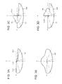
- FIG. 3A to FIG. 3D are diagrams of light distribution patterns formed by the vehicular lamp according to the first embodiment.
- FIG. 3A to FIG. 3D show the light distribution patterns formed on a virtual vertical screen set at a predetermined position in front of the lamp, for example, 25 meters ahead of the lamp.
- the light distribution pattern in FIG. 3A is a low-beam distribution pattern Lo.
- the low-beam distribution pattern Lo is a light distribution pattern set such that glare is not given to other vehicles and pedestrians in an area ahead of the host vehicle when the host vehicle is driving on the left side of a road.
- the distribution pattern Lo is formed by the lamp unit 10 when the shade 16 is in the advanced position.
- the low-beam distribution pattern Lo has, at its upper end, an oncoming lane side cut-off line CL1 which is on the right side of a vertical line V and which extends in parallel with a horizontal line H, a host vehicle travel lane side cut-off line CL2 which is on the left of the vertical line V and which extends in parallel with the horizontal line H at a position higher than the oncoming lane side cut-off line CL1, and a oblique cut-off line CL3 which extends between the oncoming lane side cut-off line CL1 and the host vehicle travel lane side cut-off line CL2 to connect the cut-off lines CL1 and CL2 to each other.
- the oblique cut-off line CL3 extends diagonally upward to the left at an inclination angle of 45° with respect to the intersection of the oncoming lane side cut-off line CL1 with the vertical line V.
- the light distribution pattern shown in FIG. 3B is a high-beam distribution pattern Hi1.
- the high-beam distribution pattern Hi1 is a light distribution pattern used to illuminate a wide area ahead of the host vehicle and an area distant from the host vehicle, and created by the lamp unit 10 when the shade 16 is in the retracted position.
- the high-beam distribution pattern Hi1 has a light radiation area above the cut-off lines of the low-beam distribution pattern Lo and on both the host vehicle travel lane side and the oncoming lane side.
- the light distribution pattern shown in FIG. 3C is a left lane high-beam distribution pattern Hi2 for forming a so-called "left lane high-beam.”
- the left lane high-beam distribution pattern Hi2 is a special high-beam distribution pattern which has a light radiation area above the cut-off lines of the low-beam distribution pattern Lo and on the host vehicle travel lane side, and has a light-blocking area on the oncoming lane side.
- the left lane high-beam distribution pattern Hi2 is formed by combining the low-beam distribution pattern Lo formed by the lamp unit 10 with a vertical cut-off line forming portion pattern P1 formed by the lamp unit 30.
- the vertical cut-off line forming portion pattern P1 is a light distribution pattern that extends in a predetermined area in the vertical direction, which is on the left side of the vertical line V and which includes the horizontal line H.
- the vertical cut-off line forming portion pattern P1 has a vertical cut-off line CLV1 that extends in the vertical direction at a position at which the vertical cut-off line CLV1 substantially coincides with the vertical line V.
- the light distribution pattern shown in FIG. 3D is a right lane high-beam distribution pattern Hi3 for forming a so-called "right lane high-beam.”
- the right lane high-beam distribution pattern Hi3 is a special high-beam distribution pattern which has a light radiation area above the cut-off line of the low-beam distribution pattern Lo and on the oncoming lane side, and has a light-blocking area on the host vehicle travel lane side.
- the right lane high-beam distribution pattern Hi3 is formed by combining the low-beam distribution pattern Lo formed by the lamp unit 10 with a vertical cut-off line forming portion pattern P2 formed by the lamp unit 30.
- the vertical cut-off line forming portion pattern P2 is a light distribution pattern that extends in a predetermined area in the vertical direction, which is on the right side of the vertical line V, and which includes the horizontal line H.
- the vertical cut-off line forming portion pattern P2 has a vertical cut-off line CLV2 that extends in the vertical direction at a position at which the vertical cut-off line substantially coincides with the vertical line V.
- the vertical cut-off line forming portion pattern P1 is formed by the lamp unit 30 of the headlamp unit disposed on the left side
- the vertical cut-off line forming portion pattern P2 is formed by the lamp unit 30 of the headlamp disposed on the right side.
- the structure of the vehicular lamp 1 is not particularly limited to this.
- only either one of the vertical cut-off line forming portion patterns P1 and P2 may be formed by the lamp units 30 of the left and right headlamp units.
- the vertical cut-off lines CLV1 and CLV2 may each be formed at a position shifted by a predetermined amount from the vertical line V to the left or to the right in the vehicle width direction.
- the optical unit 32 is configured to form the vertical cut-off line CLV1, CLV2 with the use of a long side 34af1 of the light-emitting surface 34af of the light-emitting element 34a fixed to the element mounting portion 32a.
- the positional relationship between the element mounting portion 32a of the optical unit 32 and the parabola optical system reflector 32b is determined such that the long side 34af1 of the light-emitting surface 34af forms the vertical cut-off line CLV1, CLV2.
- the positional relationship between the light-emitting element 34a and the parabola optical system reflector 32b is determined such that the long side 34af1 of the light-emitting surface 34af forms the vertical cut-off line CLV1, CLV2.
- the light-emitting element 34a is disposed such that the long sides 34af1 of the light-emitting surface 34af extend in parallel with the vertical line V.
- the parabola optical system reflector 32b is set so as to reflect, at the time of projecting a light source image which corresponds to the light-emitting surface 34af to the front of the vehicle, the light from the light-emitting element 34a such that the long side of the projected light source image extends in parallel with the vertical line V.
- the angle formed between the long side 34af1 of the light-emitting surface 34af and the vertical line V is preferably within the range of ⁇ 15° with respect to the vertical line V.
- the angle is within the range, it is easier to make the long side of the light source image, which corresponds to the long side 34af1 of the light-emitting surface 34af, coincide with the vertical cut-off line CLV1, CLV2, than when the angle falls outside the range. Therefore, it is possible to avoid increases in complexity of the structure of the optical unit 32.
- FIG. 4A is an isolux curve diagram of the vertical cut-off line forming portion pattern formed by the vehicular lamp according to the first embodiment.
- FIG. 4B is an isolux curve diagram of a vertical cut-off line forming portion pattern formed by a vehicular lamp according to a comparative example.
- FIG. 4A and FIG. 4B show isolux curves of the vertical cut-off line forming portion pattern P1 that forms part of the left lane high-beam distribution pattern, as an example.
- the lamp unit mounted on the vehicular lamp according to the comparative example to form the vertical cut-off line forming portion pattern is a common parabolic lamp unit which is conventionally known.
- the lamp unit has basically the same structure as the lamp unit 30 of the vehicular lamp 1 according to the present embodiment, but is different in that a light-emitting element is disposed such that the long sides of its light-emitting surface extend in parallel with the horizontal line H. Therefore, with the use of the vehicular lamp according to the comparative example, the short sides of light source images, which correspond to the short side of the light-emitting surface, are stacked in the vertical direction to form the vertical cut-off line CLV1.
- a light-emitting surface of a light-emitting element has higher luminous intensity and luminance in its center portion than in its peripheral edge portion. This means that the light-emitting surface of the light-emitting element has higher luminous flux density in its center portion than in its peripheral edge portion.
- the center portion of a light source image which corresponds to a center portion of the light-emitting surface, is more distant from the position where the vertical cut-off line CLV1 is to be formed, than when a vertical cut-off line is formed with the use of the long side of the light-emitting surface.
- the center portion of the light-emitting surface has high luminous intensity, and therefore the center portion of the light source image, which corresponds to the center portion of the light-emitting surface, has high illuminance. Therefore, in the vertical cut-off line forming portion pattern P1 in the comparative example, a high illuminance area of the light source image is more distant from the position where the vertical cut-off line is to be formed, than in the vertical cut-off line forming portion pattern P1 in the first embodiment.
- the vehicular lamp 1 according to the first embodiment when the vehicular lamp 1 according to the first embodiment is used, it is possible to form the vertical cut-off line forming portion pattern P1 in which the high illuminance area of the light source image is closer to the area where the vertical cut-off line is to be formed, than when the vehicular lamp according to the comparative example 1 is used.
- an outline portion of the vertical cut-off line forming portion pattern P1, which corresponds to the vertical cut-off line CLV1 is formed so as to conform to the vertical line V (the area in which the vertical cut-off line is to be formed) more closely, than when vehicular lamp in the comparative example is used. Therefore, with the use of the vehicular lamp 1 according to the first embodiment, it is possible to form the vertical cut-off line CLV1 that is clearer than that formed by the vehicular lamp according to the comparative example.
- the vehicular lamp 1 and the optical unit 32 according to the present embodiment are configured to form the vertical cut-off line CLV1, CLV2 with the use of the long side 34af1 of the generally rectangular light-emitting surface 34af of the light-emitting element 34a.
- This structure makes it possible to form the light distribution patterns that have the clear vertical cut-off lines CLV1 and CLV2 with the use of the parabolic vehicular lamp 1.
- the vehicular lamp 1 includes the lamp units 10 for forming the low-beam distribution pattern and the high-beam distribution pattern.
- the structure of the vehicular lamp 1 is not particularly limited, and the lamp units 10 may not be provided.
- a lamp unit for forming another light distribution pattern may be provided instead of or in addition to the lamp units 10.
Landscapes
- Engineering & Computer Science (AREA)
- Physics & Mathematics (AREA)
- Microelectronics & Electronic Packaging (AREA)
- Optics & Photonics (AREA)
- General Engineering & Computer Science (AREA)
- Mechanical Engineering (AREA)
- Non-Portable Lighting Devices Or Systems Thereof (AREA)
Applications Claiming Priority (1)
| Application Number | Priority Date | Filing Date | Title |
|---|---|---|---|
| JP2011011895A JP2012155891A (ja) | 2011-01-24 | 2011-01-24 | 光学ユニットおよび車両用灯具 |
Publications (2)
| Publication Number | Publication Date |
|---|---|
| EP2479063A2 true EP2479063A2 (de) | 2012-07-25 |
| EP2479063A3 EP2479063A3 (de) | 2012-12-05 |
Family
ID=45491416
Family Applications (1)
| Application Number | Title | Priority Date | Filing Date |
|---|---|---|---|
| EP12151080A Withdrawn EP2479063A3 (de) | 2011-01-24 | 2012-01-13 | Optische Einheit und Fahrzeuglampe |
Country Status (2)
| Country | Link |
|---|---|
| EP (1) | EP2479063A3 (de) |
| JP (1) | JP2012155891A (de) |
Cited By (1)
| Publication number | Priority date | Publication date | Assignee | Title |
|---|---|---|---|---|
| WO2014174196A1 (fr) * | 2013-04-25 | 2014-10-30 | Peugeot Citroen Automobiles Sa | Procédé de commande d'un système d'éclairage réglable, pour un véhicule porteur, et système d'éclairage réglable |
Citations (2)
| Publication number | Priority date | Publication date | Assignee | Title |
|---|---|---|---|---|
| JP2008226707A (ja) | 2007-03-14 | 2008-09-25 | Koito Mfg Co Ltd | 車両用灯具 |
| JP2008226706A (ja) | 2007-03-14 | 2008-09-25 | Koito Mfg Co Ltd | 車両用灯具 |
Family Cites Families (7)
| Publication number | Priority date | Publication date | Assignee | Title |
|---|---|---|---|---|
| JP4665205B2 (ja) * | 2001-07-16 | 2011-04-06 | スタンレー電気株式会社 | 灯具用線状光源 |
| JP4335621B2 (ja) * | 2003-04-25 | 2009-09-30 | スタンレー電気株式会社 | 車両用灯具 |
| JP4115921B2 (ja) * | 2003-11-04 | 2008-07-09 | 株式会社小糸製作所 | 車両用前照灯 |
| JP4624257B2 (ja) * | 2005-12-28 | 2011-02-02 | 株式会社小糸製作所 | 車両用灯具 |
| JP2007335311A (ja) * | 2006-06-16 | 2007-12-27 | Koito Mfg Co Ltd | 車輌用灯具 |
| JP4926770B2 (ja) * | 2007-03-15 | 2012-05-09 | 株式会社小糸製作所 | 車両用前照灯装置 |
| FR2963662B1 (fr) * | 2010-08-06 | 2014-11-21 | Valeo Vision | Unite optique pour dispositif de signalisation et/ou d'eclairage |
-
2011
- 2011-01-24 JP JP2011011895A patent/JP2012155891A/ja active Pending
-
2012
- 2012-01-13 EP EP12151080A patent/EP2479063A3/de not_active Withdrawn
Patent Citations (2)
| Publication number | Priority date | Publication date | Assignee | Title |
|---|---|---|---|---|
| JP2008226707A (ja) | 2007-03-14 | 2008-09-25 | Koito Mfg Co Ltd | 車両用灯具 |
| JP2008226706A (ja) | 2007-03-14 | 2008-09-25 | Koito Mfg Co Ltd | 車両用灯具 |
Cited By (4)
| Publication number | Priority date | Publication date | Assignee | Title |
|---|---|---|---|---|
| WO2014174196A1 (fr) * | 2013-04-25 | 2014-10-30 | Peugeot Citroen Automobiles Sa | Procédé de commande d'un système d'éclairage réglable, pour un véhicule porteur, et système d'éclairage réglable |
| FR3005137A1 (fr) * | 2013-04-25 | 2014-10-31 | Peugeot Citroen Automobiles Sa | Procede de commande d'un systeme d'eclairage reglable, pour un vehicule porteur |
| CN105431329A (zh) * | 2013-04-25 | 2016-03-23 | 标致·雪铁龙汽车公司 | 用于运载车辆的控制可调节照明系统的方法,以及可调节照明系统 |
| CN105431329B (zh) * | 2013-04-25 | 2018-09-07 | 标致·雪铁龙汽车公司 | 用于运载车辆的可调节照明系统及其控制方法 |
Also Published As
| Publication number | Publication date |
|---|---|
| JP2012155891A (ja) | 2012-08-16 |
| EP2479063A3 (de) | 2012-12-05 |
Similar Documents
| Publication | Publication Date | Title |
|---|---|---|
| TWI702363B (zh) | 車燈裝置及高速照明車燈模組 | |
| US9212799B2 (en) | Lamp unit | |
| JP5869223B2 (ja) | 車両用前照灯 | |
| EP2182271B1 (de) | Fahrzeuglampeneinheit und Fahrzeuglampe | |
| KR100986778B1 (ko) | 차량용 등기구 유닛 | |
| EP2366940B1 (de) | Projektionsschweinwerfer für Motorräder | |
| EP2407710B1 (de) | Fahrzeugleuchte | |
| US20120206931A1 (en) | Vehicle lighting device | |
| US8651717B2 (en) | Vehicular illumination lamp | |
| US8851726B2 (en) | Vehicle lighting apparatus | |
| JP2003123517A (ja) | 投光ユニットおよび該投光ユニットを具備するled車両用照明灯具 | |
| EP1794491A1 (de) | Led-kollimatorelement mit einem asymmetrischen kollimator | |
| EP2284435A2 (de) | Lampeneinheit für Fahrzeugscheinwerfer | |
| EP2075500B1 (de) | Fahrzeugscheinwerfer | |
| US8376598B2 (en) | Light source unit and vehicular lamp | |
| CN111076141A (zh) | 车灯模组及车灯 | |
| EP2484553B1 (de) | Fahrzeuglampe und optische Einheit dafür | |
| CN108692270B (zh) | 车灯装置 | |
| US20100002458A1 (en) | Automotive lamp and reflector for low beam and advanced forward lighting system | |
| US7753574B2 (en) | Optical module for an elliptical lighting device adapted to a given volume for a motor vehicle | |
| EP2479063A2 (de) | Optische Einheit und Fahrzeuglampe | |
| CN211450764U (zh) | 车灯模组及车灯 | |
| US20090316415A1 (en) | Lamp unit | |
| CN220582277U (zh) | 一种车灯照明模组和车灯 | |
| WO2023162906A1 (ja) | 車両用灯具 |
Legal Events
| Date | Code | Title | Description |
|---|---|---|---|
| PUAI | Public reference made under article 153(3) epc to a published international application that has entered the european phase |
Free format text: ORIGINAL CODE: 0009012 |
|
| 17P | Request for examination filed |
Effective date: 20120113 |
|
| AK | Designated contracting states |
Kind code of ref document: A2 Designated state(s): AL AT BE BG CH CY CZ DE DK EE ES FI FR GB GR HR HU IE IS IT LI LT LU LV MC MK MT NL NO PL PT RO RS SE SI SK SM TR |
|
| AX | Request for extension of the european patent |
Extension state: BA ME |
|
| PUAL | Search report despatched |
Free format text: ORIGINAL CODE: 0009013 |
|
| AK | Designated contracting states |
Kind code of ref document: A3 Designated state(s): AL AT BE BG CH CY CZ DE DK EE ES FI FR GB GR HR HU IE IS IT LI LT LU LV MC MK MT NL NO PL PT RO RS SE SI SK SM TR |
|
| AX | Request for extension of the european patent |
Extension state: BA ME |
|
| RIC1 | Information provided on ipc code assigned before grant |
Ipc: F21S 8/10 20060101ALI20121031BHEP Ipc: B60Q 1/14 20060101AFI20121031BHEP Ipc: B60Q 1/00 20060101ALI20121031BHEP |
|
| 17Q | First examination report despatched |
Effective date: 20161117 |
|
| STAA | Information on the status of an ep patent application or granted ep patent |
Free format text: STATUS: THE APPLICATION IS DEEMED TO BE WITHDRAWN |
|
| 18D | Application deemed to be withdrawn |
Effective date: 20170607 |