EP2483459B1 - Oberflächenvorbereitungseinheit für metallstreifenverarbeitungslinie - Google Patents
Oberflächenvorbereitungseinheit für metallstreifenverarbeitungslinie Download PDFInfo
- Publication number
- EP2483459B1 EP2483459B1 EP10776141.3A EP10776141A EP2483459B1 EP 2483459 B1 EP2483459 B1 EP 2483459B1 EP 10776141 A EP10776141 A EP 10776141A EP 2483459 B1 EP2483459 B1 EP 2483459B1
- Authority
- EP
- European Patent Office
- Prior art keywords
- strip
- tank
- unit according
- electrodes
- submersion
- Prior art date
- Legal status (The legal status is an assumption and is not a legal conclusion. Google has not performed a legal analysis and makes no representation as to the accuracy of the status listed.)
- Active
Links
Images
Classifications
-
- C—CHEMISTRY; METALLURGY
- C25—ELECTROLYTIC OR ELECTROPHORETIC PROCESSES; APPARATUS THEREFOR
- C25F—PROCESSES FOR THE ELECTROLYTIC REMOVAL OF MATERIALS FROM OBJECTS; APPARATUS THEREFOR
- C25F1/00—Electrolytic cleaning, degreasing, pickling or descaling
- C25F1/02—Pickling; Descaling
-
- C—CHEMISTRY; METALLURGY
- C25—ELECTROLYTIC OR ELECTROPHORETIC PROCESSES; APPARATUS THEREFOR
- C25D—PROCESSES FOR THE ELECTROLYTIC OR ELECTROPHORETIC PRODUCTION OF COATINGS; ELECTROFORMING; APPARATUS THEREFOR
- C25D17/00—Constructional parts, or assemblies thereof, of cells for electrolytic coating
- C25D17/02—Tanks; Installations therefor
-
- C—CHEMISTRY; METALLURGY
- C25—ELECTROLYTIC OR ELECTROPHORETIC PROCESSES; APPARATUS THEREFOR
- C25D—PROCESSES FOR THE ELECTROLYTIC OR ELECTROPHORETIC PRODUCTION OF COATINGS; ELECTROFORMING; APPARATUS THEREFOR
- C25D17/00—Constructional parts, or assemblies thereof, of cells for electrolytic coating
- C25D17/10—Electrodes, e.g. composition, counter electrode
- C25D17/12—Shape or form
-
- C—CHEMISTRY; METALLURGY
- C25—ELECTROLYTIC OR ELECTROPHORETIC PROCESSES; APPARATUS THEREFOR
- C25D—PROCESSES FOR THE ELECTROLYTIC OR ELECTROPHORETIC PRODUCTION OF COATINGS; ELECTROFORMING; APPARATUS THEREFOR
- C25D21/00—Processes for servicing or operating cells for electrolytic coating
- C25D21/04—Removal of gases or vapours ; Gas or pressure control
-
- C—CHEMISTRY; METALLURGY
- C25—ELECTROLYTIC OR ELECTROPHORETIC PROCESSES; APPARATUS THEREFOR
- C25D—PROCESSES FOR THE ELECTROLYTIC OR ELECTROPHORETIC PRODUCTION OF COATINGS; ELECTROFORMING; APPARATUS THEREFOR
- C25D21/00—Processes for servicing or operating cells for electrolytic coating
- C25D21/10—Agitating of electrolytes; Moving of racks
-
- C—CHEMISTRY; METALLURGY
- C25—ELECTROLYTIC OR ELECTROPHORETIC PROCESSES; APPARATUS THEREFOR
- C25D—PROCESSES FOR THE ELECTROLYTIC OR ELECTROPHORETIC PRODUCTION OF COATINGS; ELECTROFORMING; APPARATUS THEREFOR
- C25D21/00—Processes for servicing or operating cells for electrolytic coating
- C25D21/12—Process control or regulation
-
- C—CHEMISTRY; METALLURGY
- C25—ELECTROLYTIC OR ELECTROPHORETIC PROCESSES; APPARATUS THEREFOR
- C25D—PROCESSES FOR THE ELECTROLYTIC OR ELECTROPHORETIC PRODUCTION OF COATINGS; ELECTROFORMING; APPARATUS THEREFOR
- C25D21/00—Processes for servicing or operating cells for electrolytic coating
- C25D21/16—Regeneration of process solutions
- C25D21/18—Regeneration of process solutions of electrolytes
-
- C—CHEMISTRY; METALLURGY
- C25—ELECTROLYTIC OR ELECTROPHORETIC PROCESSES; APPARATUS THEREFOR
- C25D—PROCESSES FOR THE ELECTROLYTIC OR ELECTROPHORETIC PRODUCTION OF COATINGS; ELECTROFORMING; APPARATUS THEREFOR
- C25D5/00—Electroplating characterised by the process; Pretreatment or after-treatment of workpieces
- C25D5/08—Electroplating with moving electrolyte e.g. jet electroplating
-
- C—CHEMISTRY; METALLURGY
- C25—ELECTROLYTIC OR ELECTROPHORETIC PROCESSES; APPARATUS THEREFOR
- C25D—PROCESSES FOR THE ELECTROLYTIC OR ELECTROPHORETIC PRODUCTION OF COATINGS; ELECTROFORMING; APPARATUS THEREFOR
- C25D5/00—Electroplating characterised by the process; Pretreatment or after-treatment of workpieces
- C25D5/18—Electroplating using modulated, pulsed or reversing current
-
- C—CHEMISTRY; METALLURGY
- C25—ELECTROLYTIC OR ELECTROPHORETIC PROCESSES; APPARATUS THEREFOR
- C25D—PROCESSES FOR THE ELECTROLYTIC OR ELECTROPHORETIC PRODUCTION OF COATINGS; ELECTROFORMING; APPARATUS THEREFOR
- C25D7/00—Electroplating characterised by the article coated
- C25D7/06—Wires; Strips; Foils
- C25D7/0614—Strips or foils
- C25D7/0621—In horizontal cells
-
- C—CHEMISTRY; METALLURGY
- C25—ELECTROLYTIC OR ELECTROPHORETIC PROCESSES; APPARATUS THEREFOR
- C25F—PROCESSES FOR THE ELECTROLYTIC REMOVAL OF MATERIALS FROM OBJECTS; APPARATUS THEREFOR
- C25F7/00—Constructional parts, or assemblies thereof, of cells for electrolytic removal of material from objects; Servicing or operating
Definitions
- the present invention refers to a surface preparation unit for metal strips processing lines.
- surface preparation for metal strips is used for indicating the descaling and/or pickling operations.
- the conventionally most commonly used configuration is that referred to as direct current (DC) "grid to grid".
- DC direct current
- the strip generally kept at a neutral potential, often “earthed", is submerged in a conductive solution (acid or neutral) and it passes through electrodes also submerged in the electrolyte.
- the electrodes, or electrode cells, formed by extended and continuous armatures facing the two larger surfaces of the strip, are generally kept at the same potential (positive - anodic or negative - cathodic).
- the strip in these conditions, locally behaves like an armature having a sign opposite to that of the grids towards which it faces progressively.
- New processes such as those, for example, described in patent application WO 02/50344 A1 and WO 02/086199 A2 , based on the use of alternating currents, provide a valid solution to most of the abovementioned drawbacks.
- introduction thereof into conventional tanks may lead to results relatively lower than expected and this due to the fact that greater efficiency thereof only worsens the practical problems, such as for example the removal of the sludge or the evacuation of the gases produced in the electrolysis which may have a drastic impact on the operation of the tank, regardless of the process used therein.
- An object of the present invention is that of providing a surface preparation unit for metal strips processing lines for accommodating direct current, alternating current or combined alternating/direct current high efficiency electrolytic descaling and/or pickling processes.
- Another object of the present invention is that of providing a surface preparation unit for metal strips processing lines capable of disposing the high production of sludge and gas typical of the high efficiency electrolytic descaling and/or pickling processes.
- Another object of the present invention is that of providing a surface preparation unit for metal strips processing lines which is particularly simple and functional, with low costs.
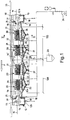
- a surface preparation unit for metal strips processing lines generally indicated with 10 is shown.
- the unit comprises a tank 12, through which a strip 11 to be treated is continuously fed in the direction of the arrow F and returned on a system for the suspension/submersion of the strip made up of a plurality of rollers.
- the tank 12 comprises a main treatment portion 12a, containing an electrolyte solution, and two opposite end portions 12b respectively bearing an input roller 13 and an output deflection roller 14, which may be coupled to a wringing roller 15.
- the end portions 12b of the tank 12 are delimited by a wall 16 for holding the electrolyte, the wall rising from a bottom wall of the tank 12.
- the end portions 12b do not contain electrolyte but they contain a valve 18 at the bottom.
- Submersion rollers 19, which divert the strip 11 beneath the free fluid surface of the electrolyte contained in the tank 12 are respectively arranged immediately downstream of the input roller 13 and immediately upstream of the output roller 14, at each end of the main treatment portion 12a.
- a partition roller 19' arranged at the centre of the tank 12, divides the path of the strip 11 into two free spans 100, each comprised between the submersion roller 19 and the partition roller 19'.
- Each free span 100 contains at least one electrode cell 20, made up of upper and lower electrodes 21 with respect to the strip 11, comprising upper and lower armatures 22, facing the two larger surfaces of the strip 11.
- Figure 1 shows two electrode cells 20 for each free span 100 spaced from each other in the longitudinal direction.
- upper or lower electrode 21 is used to indicate the complete structure that bears a given polarity facing the strip, localized in the armature 22 of the electrode 21, including the mechanical support structure as well as the electric connection one.
- the free span 100 between two successive submersion rollers 19 be preferably comprised between 3.5 m and 7 m.
- a tank 12 shall be provided with only two submersion rollers 19 should the distance between centres thereof, i.e. the free span 100 therebetween be limited between 3.5 and 7 m. Should it be larger, the tank 12 shall be provided with additional submersion rollers 19, such as the partition rollers 19', in a number such to keep each free span 100 of the strip always preferably comprised between 3.5 and 7 m.
- Such arrangement also allows defining, right from the preliminary step, the geometric parameters of the tank 12, thus optimizing both the overall dimensions and the costs of the system.
- the tank 12, according to the present invention, may contain electrode cells 20 all of the direct current type, all of the alternating current type, otherwise it may contain both direct current and alternating current cells, depending on the specific needs of the descaling/pickling process to be performed on the strip.
- the partition rollers 19' arranged between two free spans 100 lose most of their importance as electric separation elements, substantially solely maintaining the mechanical function of positioning, supporting and levelling the geometric defects of the strip 11.
- the position of the submersion rollers 19, 19' ensures that all the armatures 22 of the electrodes 21 are entirely submerged in the electrolyte.
- the strip 11, which reaches the lowest point at the partition roller 19', has - in longitudinal direction - a symmetric development inclined towards the centre of the tank 12. All the members that cooperate with the strip, i.e. the upper and lower armatures 22 and the bottom of the tank are arranged according to a development substantially parallel to the theoretical path of the strip 11 in each free span 100.
- the armatures 22 In order to eliminate scale sludge accumulations on the lower armatures 22 and gas on the upper armatures 22, the armatures 22 have, according to a preferred embodiment, a discontinuous shape having passage slots. Preferably, also the structures on which the armatures 22 are anchored have a discontinuous shape.
- Such discontinuous shape is for example made as rectangular-shaped bars having smaller dimensions in the direction of motion of the strip 11 or, alternatively, circular-shaped bars.
- the bars forming the armatures are spaced from each other to allow, through the gaps therebetween, the evacuation of the waste material thus countering the tendency of the sludge to deposit on the surfaces of the armatures 22 of the lower electrodes 21 and the gas bubbles produced by the electrochemical reactions to aggregate on the surfaces of the armature 22 of the upper electrodes 21.
- the discontinuity in the electrophysical properties of the electrolyte would alter the ideal homogeneous configuration of the flow lines of the electric field within the electrolyte between the armature and the strip with the rarefactions or accumulations random and unstable over time and hence ensuing loss of efficiency of the entire line.
- the discontinuous configuration of the bars forming the lower armatures 22 allows an easier and more effective evacuation of solid products towards the bottom of the tank 12, hence in zones far from the agitation flows of the electrolyte.
- a discontinuous configuration of the bars forming the upper armatures 22 facilitates the evacuation of the bubbles upwards beyond the surface of the liquid.
- the preferred embodiment with bar armatures 22 also opens the possibility of using different materials which due to welding fragility or difficulty are poorly suitable for continuous applications typical of the conventional armatures.
- the discontinuous shape may be obtained, for example, similar to a slot interposed between two rectangular-shaped bars extended along the direction transverse with respect to that of the motion of the strip.
- Groups of slots thus define continuous armature sections having small linear dimensions that may be fixed through methods different from welding, such as for example through special fixing means (for example bolts).
- the discontinuous shape of the armatures 22 allows alternating materials having different characteristics, possibly even different from each other incompatible in terms of electrochemical properties and/or weldability, combining and alternating conventional materials with other materials having specific features such as for example coated titanium or non-metal materials that may be more expensive.
- the construction simplification due to the use of special fixing means improve the maintenance times and the intervention complexity allowing intervening only where required.
- Means for recirculating and agitating the electrolyte also guarantee the moving of the waste material, made up of gas from the lower surface of the strip and scales undissolved from the upper surface, away from the strip 11.
- the recirculation and agitation are actuated by means of a plurality of inlet nozzles 23 for the return of the electrolyte, preferably arranged at each electrode cell 20 on the walls of the tank 12 in submerged position and substantially at the strip 11, in particular at a position slightly lower with respect to the same.
- the high flow rate electrolyte After reconditioning thereof, is introduced into the tank 12 at the "gaps", i.e. between the armatures 22, in a direction coinciding with that of the strip 11 (in co-current flow), or in the opposite direction (in countercurrent flow), depending on the geometries of the tank 12.
- the required flow rate is obtained through pumps 24 which may have high flow rate and low head or operating at normal head (about 35-45 m) that supply jet pumps.
- the electrolyte may also be introduced into the tank through the inlet mouths 25 arranged at the two ends of the tank above the free fluid surface of the electrolyte, allowing an increase of the wet surface.
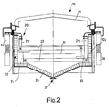
- the bottom of the tank 12 is shaped to form a hopper 26 which ends with devices 27 for evacuating the waste made up of the undissolved part of the scale, which deposits at the bottom like sludge.
- the evacuation devices 27 are made in form of evacuation bottom outlets which connect - by means of valves - the bottom of each hopper 26 with a discharge pipe 28, which is connected, in turn, with a system 29 for treating the sludgy residue material incorporating the sludge.
- the alternation of the hoppers 26 generates different agitation speeds in the electrolyte.
- the levels closest to the strip 11 are the most agitated ones, hence capable of maintaining more scales in suspension.
- the geometric shape of the hoppers 26 produces calm zones, in the electrolyte, which allow the release of the non-solubilised scaly material. Such material is accumulated at the bottom of each hopper 26 producing sludge easily removable form the discharge pipes 28.
- the hoppers 26, equivalent to the number of electrode cells 20, are provided with pipings 28 having a section such to allow to be alternatingly opened through solenoid valves managed by the system for automating the pickling in such a manner to discharge the sludge quickly without emptying the tank 12 itself.
- the tank 12 has an upper cover 30 entirely sealed and the gases produced by the clearing process as waste material, are evacuated through a plurality of gas evacuation outlets 31 arranged at the sides of the cover 30 in proximity to the ends of the tank 12 and connected to a fumes suctioning collector 32 which leads to the fumes reduction system 33.
- the surface preparation unit for metal strips processing lines 10, subject of the present invention may be used in a descaling and pickling system regardless of whether a direct current, alternating current or combined direct/alternating current electrolyte process is used.
- An electrical power supply system provides for supplying on the upper and lower armatures 22 of the AC electrode 21 the current required for operation through suitable bars or cables 34, as schematically shown in figure 2 .
- the surface preparation unit for metal strips processing lines 10, subject of the present invention is particularly advantageous for an alternating current process, wherein the electrical power supply system of the electrodes has particular new solutions.
- the electrical power supply system 34 provides for supplying onto the upper and lower armatures 22 of the AC electrode 21 the alternating current required for the operation, with a 180° phase shift between the upper and lower armature.
- the upper and lower armatures 22 of each pair of electrodes 21 are shielded between each other, in the parts not involved in the passage of the strip, due to the interposition of plastic shields 35 which contribute to support them in the position parallel to the strip preventing direct electrical contact thereof.
- the electrical power supply system of the alternating current electrodes 34 is obtained in such a manner that all the electrode cells 20 are always supplied with phase voltage with respect to each other, in such a manner that all the armatures 22 of the electrodes 21 are polarized having the same phase, and this regardless of the practical embodiment of the power supply.
- Solutions based on single-phase transformers, each operating on only one phase of the electrical power supply network, followed by current regulators or, as preferred solution, on three-phase current rectifiers energising a common DC bar followed by inverters which, without unbalanced loads between the phases of the electrical power supply network, guarantee the control of the frequency and the waveform of the AC current used, may be mentioned as non-limiting examples of power supply.
- the voltages on the upper and lower armatures 22 are asymmetric with respect to each other, but in phase with respect to the upper and lower armatures 22 of an adjacent cell 20.
- the strip 11 shall preferably be connected to earthing rollers (not shown).
- the power supply system operates regardless of the network voltage allowing an ideal choice, depending on the process performed in the tank, the required frequencies and the waveforms.
- the power supply lines for supplying one phase and the power supply lines for supplying the opposite phase are preferably positioned on opposite sides of the tank 12, as illustrated in figure 2 .
- suitable insulation materials shield and insulate the sections supplied in the tank 12 guaranteeing separate supply of two upper and lower electrodes 21 with safety, reliability and efficiency functions comparable to those of traditional tanks supplied in DC.
- the surface preparation unit for metal strips processing lines subject of the present invention has the advantage of optimising the efficiency of the process regardless of the type of power supply, entirely in alternating current, entirely in direct current or partially in alternating current and in direct current, thus also disposing the high production of sludge and gases typical of such processes.
- the dispersion of current is advantageously reduced - with the ensuing improved energy saving - in the surface preparation unit for metal strips processing lines according to the invention.
- a preferred configuration in conditions of combined power supply, provides for the arrangement of electrodes according to one or more groups of AC electrodes arranged at the inlet of the tank 12 with respect to the direction of movement of the strip, followed by one or more groups of DC electrodes in such a manner to guarantee a high descaling action with ideal conditions for finishing the strip.
- the configuration of the tank may also be advantageously adapted to the required construction geometries.
- the structure of the surface preparation unit advantageously improves the detachment of the waste material from the strip, gaseous and solid, the moving away thereof from the "gap" and the subsequent removal from the tank.
Landscapes
- Chemical & Material Sciences (AREA)
- Engineering & Computer Science (AREA)
- Chemical Kinetics & Catalysis (AREA)
- Electrochemistry (AREA)
- Materials Engineering (AREA)
- Metallurgy (AREA)
- Organic Chemistry (AREA)
- Automation & Control Theory (AREA)
- Electroplating Methods And Accessories (AREA)
- Electrolytic Production Of Metals (AREA)
- Chemically Coating (AREA)
Claims (12)
- Oberflächenbehandlungseinheit für Verarbeitungslinien für Metallstreifen, mit einem Tank (12), der zur Aufnahme einer Elektrolytlösung geeignet ist, einem System für die Suspension/Tauchung eines zu behandelnden Streifens (11), der kontinuierlich dem Tank (12) in Längsrichtung (F) zugeführt wird, einer Mehrzahl von Elektrodenzellen (20), die obere und untere Elektroden (21) umfassen, die jeweils obere und untere Armaturen (22) umfassen, die den beiden größeren Flächen des Streifens (11) zugewandt und von diesen durch einen Abstand beabstandet sind, der als "oberer Spalt" bzw. "unterer Spalt" bezeichnet ist, wobei die Elektroden (21) mit einem elektrischen Energieversorgungssystem (34) verbunden sind, wobei der Tank (12) an dem Boden so geformt ist, um aufeinanderfolgende Trichter (26) zu bilden, wobei die Oberflächenbehandlungseinheit dadurch gekennzeichnet ist, dass an jeder der Elektrodenzellen (20) einer der Trichter (26) vorgesehen ist, der mit Vorrichtungen (27) zum Evakuieren des Abfallmaterials in der Form von ungelöstem Zunder endet, der sich an dem Boden in der Form eines Schlammes abscheidet, wobei die Elektroden (21) eine diskontinuierliche Form besitzen, wobei die oberen und unteren Armaturen (22) der Elektroden aus einer Mehrzahl von Stangen bestehen, die voneinander beabstandet sind, um Spalte dazwischen für die Evakuierung von Abfallmaterial in der Form eines Gases oder von zunderartigen Schlämmen zu bilden.
- Einheit nach Anspruch 1, dadurch gekennzeichnet, dass das System für die Suspension/Tauchung des Streifens zumindest eine Eingangswalze (13) und eine Ausgangs-Ablenkwalze (14) wie auch zumindest eine Tauchwalze (19) an jedem Ende umfasst, wobei die zumindest eine Tauchwalze (19) an jedem Ende jeweils stromabwärts der Eingangswalze (13) und stromaufwärts der Ausgangsablenkwalze (14) angeordnet ist, um den Streifen (11) unterhalb der freien Fluidfläche des in dem Tank (12) enthaltenen Elektrolyts umzulenken, wobei die Tauchwalzen (19) auf solche Weise beabstandet sind, um eine freie Spanne (100) bereitzustellen, die zwischen 3,5 m und 7 m umfasst.
- Einheit nach Anspruch 2, dadurch gekennzeichnet, dass sie für Längenwerte des Tanks (12), die 7 m überschreiten, zumindest eine weitere Aufteilungstauchwalze (19') umfasst, die dem Pfad des Streifens (11) in zumindest zwei freie Spannen (100) trennt, die jeweils zumindest eine Elektrodenzelle (20) enthalten.
- Einheit nach Anspruch 3, dadurch gekennzeichnet, dass in jeder freien Spanne (100) der Boden des Tanks (12) und die oberen und unteren Armaturen (22) im Wesentlichen parallel zu dem theoretischen Pfad des Streifens (11) zwischen den Tauchwalzen (19, 19') angeordnet sind.
- Einheit nach einem der vorhergehenden Ansprüche, dadurch gekennzeichnet, dass die oberen und unteren Armaturen (22) jedes Paares von Elektroden (21) zwischen einander durch Anordnen von Kunststoffabschirmungen (35) abgeschirmt sind, die diese in der Position parallel zu dem Streifen (11) tragen, wodurch ein direkter elektrischer Kontakt davon verhindert wird.
- Einheit nach einem der vorhergehenden Ansprüche, dadurch gekennzeichnet, dass sie ein Mittel zum Rezirkulieren und Rühren des Elektrolyts umfasst, wobei das Mittel geeignet ist, ein Bewegen von Abfallmaterialien weg von dem Streifen (11) zu unterstützen, wobei das Abfallmaterial aus Gas von der Fläche unterhalb des Streifens (11) und Zunderschlamm von der oberen Fläche besteht.
- Einheit nach Anspruch 6, dadurch gekennzeichnet, dass das Mittel zum Rezirkulieren und Rühren des Elektrolyts eine Mehrzahl von Einlassdüsen (23) zum Rückführen des Elektrolyt mit einem hohen Durchfluss umfasst, wobei die Rückführeinlassdüsen (23) in einer untergetauchten Position an jeder Elektrodenzelle (20) im Wesentlichen auf dem Streifenniveau (11) angeordnet sind.
- Einheit nach Anspruch 1, dadurch gekennzeichnet, dass das Mittel (27) zum Evakuieren von Abfallmaterial in der Form von ungelöstem Zunder eine Bodenevakuierungsöffnung umfasst, die - mittels eines Ventils - den Trichter (26) mit einem Austragsrohr (28) verbindet, das seinerseits mit einem System (29) zum Behandeln von zunderhaltigem Schlammrückstandsmaterial verbunden ist.
- Einheit nach Anspruch 8, dadurch gekennzeichnet, dass die Ventile Solenoidventile sind, die alternativ jeden Trichter (26) auf eine Weise öffnen, um den Schlamm schnell ohne Lehren des Tanks (12) auszutragen.
- Einheit nacheinem der vorhergehenden Ansprüche, dadurch gekennzeichnet, dass das System zum Liefern elektrischer Leistung an die Elektroden (34) die oberen und unteren Armaturen (22) jeder Zelle (20) der Elektroden (21) mit Wechselstrom beliefert, wobei der Wechselstrom um 180° dazwischen phasenverschoben ist, wobei alle Elektrodenzellen stets mit in Phase befindlicher Spannung beliefert werden.
- Einheit nach Anspruch 10, dadurch gekennzeichnet, dass die elektrische Energieversorgung (34) einphasige Wandler, die jeweils an nur einer Phase des elektrischen Energieversorgungsnetzes arbeiten, gefolgt durch Stromregler umfasst.
- Einheit nach Anspruch 10, dadurch gekennzeichnet, dass die elektrische Energieversorgung (34) dreiphasige Stromgleichrichter umfasst, die eine Gleichstromschiene mit Leistung beaufschlagen, gefolgt durch Wechselrichter, die zum Vermeiden von unausgeglichenen Lasten zwischen den Phasen des elektrischen Energieversorgungsnetzwerks ein Steuern der Frequenz und Wellenform des AC-Stromes ungeachtet der Versorgungsspannung garantieren.
Applications Claiming Priority (2)
| Application Number | Priority Date | Filing Date | Title |
|---|---|---|---|
| ITMI2009A001681A IT1395853B1 (it) | 2009-09-30 | 2009-09-30 | Gruppo di preparazione superficiale per linee di produzione di nastri metallici |
| PCT/IB2010/002402 WO2011039596A1 (en) | 2009-09-30 | 2010-09-24 | Surface preparation unit for metal strips processing lines |
Publications (2)
| Publication Number | Publication Date |
|---|---|
| EP2483459A1 EP2483459A1 (de) | 2012-08-08 |
| EP2483459B1 true EP2483459B1 (de) | 2017-06-14 |
Family
ID=42184098
Family Applications (1)
| Application Number | Title | Priority Date | Filing Date |
|---|---|---|---|
| EP10776141.3A Active EP2483459B1 (de) | 2009-09-30 | 2010-09-24 | Oberflächenvorbereitungseinheit für metallstreifenverarbeitungslinie |
Country Status (4)
| Country | Link |
|---|---|
| EP (1) | EP2483459B1 (de) |
| CN (1) | CN102713023B (de) |
| IT (1) | IT1395853B1 (de) |
| WO (1) | WO2011039596A1 (de) |
Families Citing this family (5)
| Publication number | Priority date | Publication date | Assignee | Title |
|---|---|---|---|---|
| ITMI20130493A1 (it) | 2013-03-29 | 2014-09-30 | Tenova Spa | Metodo per trattare in continuo la superficie di un laminato di acciaio inossidabile in una soluzione a base di acido solforico |
| ITMI20130494A1 (it) | 2013-03-29 | 2014-09-30 | Tenova Spa | Metodo per trattare in continuo la superficie di un laminato di acciaio inossidabile in una soluzione a base di acido cloridrico |
| ITMI20130497A1 (it) | 2013-03-29 | 2014-09-30 | Tenova Spa | Apparato per il trattamento elettrolitico superficiale in continuo di semilavorati metallici, in particolare semilavorati metallici piatti. |
| CN104928738B (zh) * | 2015-05-21 | 2017-04-19 | 中国科学院山西煤炭化学研究所 | 一种碳纤维丝束的连续电镀金属方法及装置 |
| CN105220213A (zh) * | 2015-10-24 | 2016-01-06 | 本钢不锈钢冷轧丹东有限责任公司 | 中性盐电解槽 |
Family Cites Families (8)
| Publication number | Priority date | Publication date | Assignee | Title |
|---|---|---|---|---|
| US4859298A (en) * | 1988-12-07 | 1989-08-22 | Chemcut Corporation | Process and apparatus for electrolytically removing protective layers from sheet metal substrate |
| CN2148766Y (zh) * | 1992-11-04 | 1993-12-08 | 鞍山钢铁公司 | 金属制品表面电化学连续预处理装置 |
| AT405060B (de) * | 1996-04-12 | 1999-05-25 | Andritz Patentverwaltung | Verfahren und vorrichtung zur elektrolytischen behandlung von durchlaufendem gut |
| JP3357032B2 (ja) * | 1999-12-21 | 2002-12-16 | ハセ技研株式会社 | めっき処理装置およびめっき処理方法 |
| IT1318919B1 (it) * | 2000-09-22 | 2003-09-19 | Danieli Hi Tech Gmbh | Processo e dispositivo per il trattamento elettrolitico superficialedi nastri di metallo. |
| EP1358367B1 (de) | 2000-12-18 | 2004-09-15 | CENTRO SVILUPPO MATERIALI S.p.A. | Kontinuierliches elektrolytisches beizen und entzundern von unlegiertem stahl und nichtrostendem stahl |
| ITRM20010223A1 (it) | 2001-04-24 | 2002-10-24 | Ct Sviluppo Materiali Spa | Metodo per la descagliatura elettrolitica continua di acciai inossidabili in presenza di effetti indiretti del passaggio di corrente. |
| AT413707B (de) * | 2004-07-19 | 2006-05-15 | Voest Alpine Ind Anlagen | Verfahren und vorrichtung zum beizen von metallen |
-
2009
- 2009-09-30 IT ITMI2009A001681A patent/IT1395853B1/it active
-
2010
- 2010-09-24 WO PCT/IB2010/002402 patent/WO2011039596A1/en not_active Ceased
- 2010-09-24 EP EP10776141.3A patent/EP2483459B1/de active Active
- 2010-09-24 CN CN201080042867.3A patent/CN102713023B/zh active Active
Also Published As
| Publication number | Publication date |
|---|---|
| EP2483459A1 (de) | 2012-08-08 |
| ITMI20091681A1 (it) | 2011-04-01 |
| CN102713023B (zh) | 2015-12-16 |
| WO2011039596A1 (en) | 2011-04-07 |
| IT1395853B1 (it) | 2012-10-26 |
| CN102713023A (zh) | 2012-10-03 |
Similar Documents
| Publication | Publication Date | Title |
|---|---|---|
| US7309408B2 (en) | Industrial wastewater treatment and metals recovery apparatus | |
| EP2483459B1 (de) | Oberflächenvorbereitungseinheit für metallstreifenverarbeitungslinie | |
| EP1115908B1 (de) | Erdgas-unterstüzter dampfelektrolyseur | |
| US4755305A (en) | Continuous dewatering method | |
| CN100591629C (zh) | 一种高频脉冲电化学废水处理工艺及其装置 | |
| EP2150500B1 (de) | Elektrokoagulationszelle | |
| CA2696635C (en) | Process for the operation of copper electrolysis cells | |
| US3650935A (en) | Apparatus for electrolytic surface treatment | |
| GB2071155A (en) | Electrolytically treating a metal strip | |
| CN102010037A (zh) | 一种标准化电絮凝设备设计方案 | |
| CN203065598U (zh) | 熔炼设备 | |
| CN101516785A (zh) | 用于从液体中去除有害物质的方法以及用于实施该方法的设备 | |
| CN106882887A (zh) | 用于重污染有机废水连续性预处理反应器 | |
| CN105776447A (zh) | 一种长效旋转圆锥型电絮凝装置 | |
| PL96577B1 (pl) | Sposob elektrolizy metali kolorowych i urzadzenie do elektrolizy metali kolorowych | |
| AU2005263476A1 (en) | Method and device for descaling metals | |
| IT201800009628A1 (it) | Processo e apparecchiatura di elettrocoagulazione per trattamenti di depurazione di liquidi contaminati | |
| SU1000406A1 (ru) | Электролизер дл очистки сточных вод | |
| CA1180681A (en) | Guide baffles upstream of electrode channels to provide uniform flow | |
| KR200227263Y1 (ko) | 접촉면적을 극대화시킨 경사판침전조 | |
| KR200223757Y1 (ko) | 전기분해와 경사판을 이용한 오폐수처리장치 | |
| KR20070031981A (ko) | 전극판 고정장치를 이용한 폐수처리장치와 그 제작방법 | |
| KR101052606B1 (ko) | 폐광산 갱내수 정화를 위한 전기분해 일렬 순환시스템 | |
| CN219217666U (zh) | 一种脉冲电解气浮污水处理设备 | |
| CN222574407U (zh) | 电化学污水处理装置 |
Legal Events
| Date | Code | Title | Description |
|---|---|---|---|
| PUAI | Public reference made under article 153(3) epc to a published international application that has entered the european phase |
Free format text: ORIGINAL CODE: 0009012 |
|
| 17P | Request for examination filed |
Effective date: 20120307 |
|
| AK | Designated contracting states |
Kind code of ref document: A1 Designated state(s): AL AT BE BG CH CY CZ DE DK EE ES FI FR GB GR HR HU IE IS IT LI LT LU LV MC MK MT NL NO PL PT RO SE SI SK SM TR |
|
| DAX | Request for extension of the european patent (deleted) | ||
| GRAP | Despatch of communication of intention to grant a patent |
Free format text: ORIGINAL CODE: EPIDOSNIGR1 |
|
| STAA | Information on the status of an ep patent application or granted ep patent |
Free format text: STATUS: GRANT OF PATENT IS INTENDED |
|
| INTG | Intention to grant announced |
Effective date: 20170104 |
|
| GRAS | Grant fee paid |
Free format text: ORIGINAL CODE: EPIDOSNIGR3 |
|
| GRAA | (expected) grant |
Free format text: ORIGINAL CODE: 0009210 |
|
| STAA | Information on the status of an ep patent application or granted ep patent |
Free format text: STATUS: THE PATENT HAS BEEN GRANTED |
|
| AK | Designated contracting states |
Kind code of ref document: B1 Designated state(s): AL AT BE BG CH CY CZ DE DK EE ES FI FR GB GR HR HU IE IS IT LI LT LU LV MC MK MT NL NO PL PT RO SE SI SK SM TR |
|
| REG | Reference to a national code |
Ref country code: GB Ref legal event code: FG4D |
|
| REG | Reference to a national code |
Ref country code: CH Ref legal event code: EP Ref country code: AT Ref legal event code: REF Ref document number: 901037 Country of ref document: AT Kind code of ref document: T Effective date: 20170615 |
|
| REG | Reference to a national code |
Ref country code: IE Ref legal event code: FG4D |
|
| REG | Reference to a national code |
Ref country code: DE Ref legal event code: R096 Ref document number: 602010042987 Country of ref document: DE |
|
| REG | Reference to a national code |
Ref country code: FR Ref legal event code: PLFP Year of fee payment: 8 |
|
| REG | Reference to a national code |
Ref country code: NL Ref legal event code: FP |
|
| REG | Reference to a national code |
Ref country code: SE Ref legal event code: TRGR |
|
| REG | Reference to a national code |
Ref country code: LT Ref legal event code: MG4D |
|
| PG25 | Lapsed in a contracting state [announced via postgrant information from national office to epo] |
Ref country code: HR Free format text: LAPSE BECAUSE OF FAILURE TO SUBMIT A TRANSLATION OF THE DESCRIPTION OR TO PAY THE FEE WITHIN THE PRESCRIBED TIME-LIMIT Effective date: 20170614 Ref country code: GR Free format text: LAPSE BECAUSE OF FAILURE TO SUBMIT A TRANSLATION OF THE DESCRIPTION OR TO PAY THE FEE WITHIN THE PRESCRIBED TIME-LIMIT Effective date: 20170915 Ref country code: NO Free format text: LAPSE BECAUSE OF FAILURE TO SUBMIT A TRANSLATION OF THE DESCRIPTION OR TO PAY THE FEE WITHIN THE PRESCRIBED TIME-LIMIT Effective date: 20170914 Ref country code: LT Free format text: LAPSE BECAUSE OF FAILURE TO SUBMIT A TRANSLATION OF THE DESCRIPTION OR TO PAY THE FEE WITHIN THE PRESCRIBED TIME-LIMIT Effective date: 20170614 Ref country code: ES Free format text: LAPSE BECAUSE OF FAILURE TO SUBMIT A TRANSLATION OF THE DESCRIPTION OR TO PAY THE FEE WITHIN THE PRESCRIBED TIME-LIMIT Effective date: 20170614 |
|
| REG | Reference to a national code |
Ref country code: AT Ref legal event code: MK05 Ref document number: 901037 Country of ref document: AT Kind code of ref document: T Effective date: 20170614 |
|
| PG25 | Lapsed in a contracting state [announced via postgrant information from national office to epo] |
Ref country code: BG Free format text: LAPSE BECAUSE OF FAILURE TO SUBMIT A TRANSLATION OF THE DESCRIPTION OR TO PAY THE FEE WITHIN THE PRESCRIBED TIME-LIMIT Effective date: 20170914 Ref country code: LV Free format text: LAPSE BECAUSE OF FAILURE TO SUBMIT A TRANSLATION OF THE DESCRIPTION OR TO PAY THE FEE WITHIN THE PRESCRIBED TIME-LIMIT Effective date: 20170614 |
|
| PG25 | Lapsed in a contracting state [announced via postgrant information from national office to epo] |
Ref country code: RO Free format text: LAPSE BECAUSE OF FAILURE TO SUBMIT A TRANSLATION OF THE DESCRIPTION OR TO PAY THE FEE WITHIN THE PRESCRIBED TIME-LIMIT Effective date: 20170614 Ref country code: AT Free format text: LAPSE BECAUSE OF FAILURE TO SUBMIT A TRANSLATION OF THE DESCRIPTION OR TO PAY THE FEE WITHIN THE PRESCRIBED TIME-LIMIT Effective date: 20170614 Ref country code: EE Free format text: LAPSE BECAUSE OF FAILURE TO SUBMIT A TRANSLATION OF THE DESCRIPTION OR TO PAY THE FEE WITHIN THE PRESCRIBED TIME-LIMIT Effective date: 20170614 Ref country code: SK Free format text: LAPSE BECAUSE OF FAILURE TO SUBMIT A TRANSLATION OF THE DESCRIPTION OR TO PAY THE FEE WITHIN THE PRESCRIBED TIME-LIMIT Effective date: 20170614 |
|
| PG25 | Lapsed in a contracting state [announced via postgrant information from national office to epo] |
Ref country code: IS Free format text: LAPSE BECAUSE OF FAILURE TO SUBMIT A TRANSLATION OF THE DESCRIPTION OR TO PAY THE FEE WITHIN THE PRESCRIBED TIME-LIMIT Effective date: 20171014 Ref country code: PL Free format text: LAPSE BECAUSE OF FAILURE TO SUBMIT A TRANSLATION OF THE DESCRIPTION OR TO PAY THE FEE WITHIN THE PRESCRIBED TIME-LIMIT Effective date: 20170614 Ref country code: SM Free format text: LAPSE BECAUSE OF FAILURE TO SUBMIT A TRANSLATION OF THE DESCRIPTION OR TO PAY THE FEE WITHIN THE PRESCRIBED TIME-LIMIT Effective date: 20170614 |
|
| REG | Reference to a national code |
Ref country code: DE Ref legal event code: R097 Ref document number: 602010042987 Country of ref document: DE |
|
| PLBE | No opposition filed within time limit |
Free format text: ORIGINAL CODE: 0009261 |
|
| STAA | Information on the status of an ep patent application or granted ep patent |
Free format text: STATUS: NO OPPOSITION FILED WITHIN TIME LIMIT |
|
| PG25 | Lapsed in a contracting state [announced via postgrant information from national office to epo] |
Ref country code: DK Free format text: LAPSE BECAUSE OF FAILURE TO SUBMIT A TRANSLATION OF THE DESCRIPTION OR TO PAY THE FEE WITHIN THE PRESCRIBED TIME-LIMIT Effective date: 20170614 |
|
| REG | Reference to a national code |
Ref country code: CH Ref legal event code: PL |
|
| 26N | No opposition filed |
Effective date: 20180315 |
|
| GBPC | Gb: european patent ceased through non-payment of renewal fee |
Effective date: 20170924 |
|
| PG25 | Lapsed in a contracting state [announced via postgrant information from national office to epo] |
Ref country code: MC Free format text: LAPSE BECAUSE OF FAILURE TO SUBMIT A TRANSLATION OF THE DESCRIPTION OR TO PAY THE FEE WITHIN THE PRESCRIBED TIME-LIMIT Effective date: 20170614 |
|
| REG | Reference to a national code |
Ref country code: IE Ref legal event code: MM4A |
|
| PG25 | Lapsed in a contracting state [announced via postgrant information from national office to epo] |
Ref country code: LU Free format text: LAPSE BECAUSE OF NON-PAYMENT OF DUE FEES Effective date: 20170924 |
|
| PG25 | Lapsed in a contracting state [announced via postgrant information from national office to epo] |
Ref country code: CH Free format text: LAPSE BECAUSE OF NON-PAYMENT OF DUE FEES Effective date: 20170930 Ref country code: IE Free format text: LAPSE BECAUSE OF NON-PAYMENT OF DUE FEES Effective date: 20170924 Ref country code: GB Free format text: LAPSE BECAUSE OF NON-PAYMENT OF DUE FEES Effective date: 20170924 Ref country code: LI Free format text: LAPSE BECAUSE OF NON-PAYMENT OF DUE FEES Effective date: 20170930 |
|
| PG25 | Lapsed in a contracting state [announced via postgrant information from national office to epo] |
Ref country code: SI Free format text: LAPSE BECAUSE OF FAILURE TO SUBMIT A TRANSLATION OF THE DESCRIPTION OR TO PAY THE FEE WITHIN THE PRESCRIBED TIME-LIMIT Effective date: 20170614 |
|
| REG | Reference to a national code |
Ref country code: FR Ref legal event code: PLFP Year of fee payment: 9 |
|
| PG25 | Lapsed in a contracting state [announced via postgrant information from national office to epo] |
Ref country code: MT Free format text: LAPSE BECAUSE OF NON-PAYMENT OF DUE FEES Effective date: 20170924 |
|
| PG25 | Lapsed in a contracting state [announced via postgrant information from national office to epo] |
Ref country code: HU Free format text: LAPSE BECAUSE OF FAILURE TO SUBMIT A TRANSLATION OF THE DESCRIPTION OR TO PAY THE FEE WITHIN THE PRESCRIBED TIME-LIMIT; INVALID AB INITIO Effective date: 20100924 |
|
| PG25 | Lapsed in a contracting state [announced via postgrant information from national office to epo] |
Ref country code: CY Free format text: LAPSE BECAUSE OF NON-PAYMENT OF DUE FEES Effective date: 20170614 |
|
| PG25 | Lapsed in a contracting state [announced via postgrant information from national office to epo] |
Ref country code: MK Free format text: LAPSE BECAUSE OF FAILURE TO SUBMIT A TRANSLATION OF THE DESCRIPTION OR TO PAY THE FEE WITHIN THE PRESCRIBED TIME-LIMIT Effective date: 20170614 |
|
| PG25 | Lapsed in a contracting state [announced via postgrant information from national office to epo] |
Ref country code: TR Free format text: LAPSE BECAUSE OF FAILURE TO SUBMIT A TRANSLATION OF THE DESCRIPTION OR TO PAY THE FEE WITHIN THE PRESCRIBED TIME-LIMIT Effective date: 20170614 |
|
| PG25 | Lapsed in a contracting state [announced via postgrant information from national office to epo] |
Ref country code: PT Free format text: LAPSE BECAUSE OF FAILURE TO SUBMIT A TRANSLATION OF THE DESCRIPTION OR TO PAY THE FEE WITHIN THE PRESCRIBED TIME-LIMIT Effective date: 20170614 |
|
| PG25 | Lapsed in a contracting state [announced via postgrant information from national office to epo] |
Ref country code: AL Free format text: LAPSE BECAUSE OF FAILURE TO SUBMIT A TRANSLATION OF THE DESCRIPTION OR TO PAY THE FEE WITHIN THE PRESCRIBED TIME-LIMIT Effective date: 20170614 |
|
| P01 | Opt-out of the competence of the unified patent court (upc) registered |
Effective date: 20230505 |
|
| PGFP | Annual fee paid to national office [announced via postgrant information from national office to epo] |
Ref country code: FI Payment date: 20250925 Year of fee payment: 16 |
|
| PGFP | Annual fee paid to national office [announced via postgrant information from national office to epo] |
Ref country code: DE Payment date: 20250929 Year of fee payment: 16 |
|
| PGFP | Annual fee paid to national office [announced via postgrant information from national office to epo] |
Ref country code: NL Payment date: 20250926 Year of fee payment: 16 Ref country code: IT Payment date: 20250919 Year of fee payment: 16 |
|
| PGFP | Annual fee paid to national office [announced via postgrant information from national office to epo] |
Ref country code: BE Payment date: 20250929 Year of fee payment: 16 |
|
| PGFP | Annual fee paid to national office [announced via postgrant information from national office to epo] |
Ref country code: FR Payment date: 20250925 Year of fee payment: 16 |
|
| PGFP | Annual fee paid to national office [announced via postgrant information from national office to epo] |
Ref country code: SE Payment date: 20250927 Year of fee payment: 16 |
|
| PGFP | Annual fee paid to national office [announced via postgrant information from national office to epo] |
Ref country code: CZ Payment date: 20250908 Year of fee payment: 16 |