EP2482774B1 - Procédé de fixation de languettes de saisie d'une couche de support de pansement film - Google Patents
Procédé de fixation de languettes de saisie d'une couche de support de pansement film Download PDFInfo
- Publication number
- EP2482774B1 EP2482774B1 EP10820900.8A EP10820900A EP2482774B1 EP 2482774 B1 EP2482774 B1 EP 2482774B1 EP 10820900 A EP10820900 A EP 10820900A EP 2482774 B1 EP2482774 B1 EP 2482774B1
- Authority
- EP
- European Patent Office
- Prior art keywords
- carrier layer
- film
- layer
- web
- strip
- Prior art date
- Legal status (The legal status is an assumption and is not a legal conclusion. Google has not performed a legal analysis and makes no representation as to the accuracy of the status listed.)
- Active
Links
- 238000000034 method Methods 0.000 title claims description 18
- 239000000463 material Substances 0.000 claims description 29
- 238000003466 welding Methods 0.000 claims description 24
- 239000000853 adhesive Substances 0.000 claims description 21
- 230000001070 adhesive effect Effects 0.000 claims description 21
- 238000005520 cutting process Methods 0.000 claims description 18
- 239000011248 coating agent Substances 0.000 claims description 8
- 238000000576 coating method Methods 0.000 claims description 8
- -1 polyethylene Polymers 0.000 claims description 8
- 239000012815 thermoplastic material Substances 0.000 claims description 6
- 239000004743 Polypropylene Substances 0.000 claims description 5
- 229920001155 polypropylene Polymers 0.000 claims description 5
- 239000004698 Polyethylene Substances 0.000 claims description 4
- 229920000573 polyethylene Polymers 0.000 claims description 4
- 229920001296 polysiloxane Polymers 0.000 claims description 4
- 229920002635 polyurethane Polymers 0.000 claims description 3
- 239000004814 polyurethane Substances 0.000 claims description 3
- 239000010410 layer Substances 0.000 description 94
- 238000004519 manufacturing process Methods 0.000 description 7
- 238000002604 ultrasonography Methods 0.000 description 3
- 238000004806 packaging method and process Methods 0.000 description 2
- NIXOWILDQLNWCW-UHFFFAOYSA-M Acrylate Chemical compound [O-]C(=O)C=C NIXOWILDQLNWCW-UHFFFAOYSA-M 0.000 description 1
- 241000743339 Agrostis Species 0.000 description 1
- 229920000219 Ethylene vinyl alcohol Polymers 0.000 description 1
- XUIMIQQOPSSXEZ-UHFFFAOYSA-N Silicon Chemical compound [Si] XUIMIQQOPSSXEZ-UHFFFAOYSA-N 0.000 description 1
- 239000012790 adhesive layer Substances 0.000 description 1
- 238000005452 bending Methods 0.000 description 1
- 238000004049 embossing Methods 0.000 description 1
- 239000004715 ethylene vinyl alcohol Substances 0.000 description 1
- RZXDTJIXPSCHCI-UHFFFAOYSA-N hexa-1,5-diene-2,5-diol Chemical compound OC(=C)CCC(O)=C RZXDTJIXPSCHCI-UHFFFAOYSA-N 0.000 description 1
- 239000002985 plastic film Substances 0.000 description 1
- 229920006255 plastic film Polymers 0.000 description 1
- 229920000728 polyester Polymers 0.000 description 1
- 229920000098 polyolefin Polymers 0.000 description 1
- 229910052710 silicon Inorganic materials 0.000 description 1
- 239000010703 silicon Substances 0.000 description 1
- 239000013464 silicone adhesive Substances 0.000 description 1
- 238000003860 storage Methods 0.000 description 1
Images
Classifications
-
- A—HUMAN NECESSITIES
- A61—MEDICAL OR VETERINARY SCIENCE; HYGIENE
- A61F—FILTERS IMPLANTABLE INTO BLOOD VESSELS; PROSTHESES; DEVICES PROVIDING PATENCY TO, OR PREVENTING COLLAPSING OF, TUBULAR STRUCTURES OF THE BODY, e.g. STENTS; ORTHOPAEDIC, NURSING OR CONTRACEPTIVE DEVICES; FOMENTATION; TREATMENT OR PROTECTION OF EYES OR EARS; BANDAGES, DRESSINGS OR ABSORBENT PADS; FIRST-AID KITS
- A61F13/00—Bandages or dressings; Absorbent pads
- A61F13/02—Adhesive bandages or dressings
- A61F13/0276—Apparatus or processes for manufacturing adhesive dressings or bandages
- A61F13/0289—Apparatus or processes for manufacturing adhesive dressings or bandages manufacturing of adhesive dressings
-
- A—HUMAN NECESSITIES
- A61—MEDICAL OR VETERINARY SCIENCE; HYGIENE
- A61F—FILTERS IMPLANTABLE INTO BLOOD VESSELS; PROSTHESES; DEVICES PROVIDING PATENCY TO, OR PREVENTING COLLAPSING OF, TUBULAR STRUCTURES OF THE BODY, e.g. STENTS; ORTHOPAEDIC, NURSING OR CONTRACEPTIVE DEVICES; FOMENTATION; TREATMENT OR PROTECTION OF EYES OR EARS; BANDAGES, DRESSINGS OR ABSORBENT PADS; FIRST-AID KITS
- A61F13/00—Bandages or dressings; Absorbent pads
- A61F13/02—Adhesive bandages or dressings
- A61F13/0203—Adhesive bandages or dressings with fluid retention members
- A61F13/022—Adhesive bandages or dressings with fluid retention members having more than one layer with different fluid retention characteristics
-
- A—HUMAN NECESSITIES
- A61—MEDICAL OR VETERINARY SCIENCE; HYGIENE
- A61F—FILTERS IMPLANTABLE INTO BLOOD VESSELS; PROSTHESES; DEVICES PROVIDING PATENCY TO, OR PREVENTING COLLAPSING OF, TUBULAR STRUCTURES OF THE BODY, e.g. STENTS; ORTHOPAEDIC, NURSING OR CONTRACEPTIVE DEVICES; FOMENTATION; TREATMENT OR PROTECTION OF EYES OR EARS; BANDAGES, DRESSINGS OR ABSORBENT PADS; FIRST-AID KITS
- A61F13/00—Bandages or dressings; Absorbent pads
- A61F13/02—Adhesive bandages or dressings
- A61F13/023—Adhesive bandages or dressings wound covering film layers without a fluid retention layer
- A61F13/0236—Adhesive bandages or dressings wound covering film layers without a fluid retention layer characterised by the application/handling support layer
- A61F13/024—Adhesive bandages or dressings wound covering film layers without a fluid retention layer characterised by the application/handling support layer the application or handling support layer being removable
-
- A—HUMAN NECESSITIES
- A61—MEDICAL OR VETERINARY SCIENCE; HYGIENE
- A61F—FILTERS IMPLANTABLE INTO BLOOD VESSELS; PROSTHESES; DEVICES PROVIDING PATENCY TO, OR PREVENTING COLLAPSING OF, TUBULAR STRUCTURES OF THE BODY, e.g. STENTS; ORTHOPAEDIC, NURSING OR CONTRACEPTIVE DEVICES; FOMENTATION; TREATMENT OR PROTECTION OF EYES OR EARS; BANDAGES, DRESSINGS OR ABSORBENT PADS; FIRST-AID KITS
- A61F13/00—Bandages or dressings; Absorbent pads
- A61F2013/00361—Plasters
- A61F2013/00795—Plasters special helping devices
- A61F2013/008—Plasters special helping devices easy removing of the protection sheet
-
- A—HUMAN NECESSITIES
- A61—MEDICAL OR VETERINARY SCIENCE; HYGIENE
- A61F—FILTERS IMPLANTABLE INTO BLOOD VESSELS; PROSTHESES; DEVICES PROVIDING PATENCY TO, OR PREVENTING COLLAPSING OF, TUBULAR STRUCTURES OF THE BODY, e.g. STENTS; ORTHOPAEDIC, NURSING OR CONTRACEPTIVE DEVICES; FOMENTATION; TREATMENT OR PROTECTION OF EYES OR EARS; BANDAGES, DRESSINGS OR ABSORBENT PADS; FIRST-AID KITS
- A61F13/00—Bandages or dressings; Absorbent pads
- A61F2013/00361—Plasters
- A61F2013/00795—Plasters special helping devices
- A61F2013/00817—Plasters special helping devices handles or handling tabs
Definitions
- the invention relates to a method of attaching a grip tab to at least one of two opposite edges of a releasable carrier layer of a film dressing web, said web includes a film layer on a first side coated with adhesive and a carrier layer releasably attached to the film layer on a second side thereof being opposite to the first side, the film layer and the carrier layer having the same dimensions, and a film dressing manufactured by said method.
- Film dressings consist in use of a thin plastic film coated with an adhesive. Due to its thin nature it is almost impossible to apply such an adhesively coated film. For this reason film dressings are provided with releasable carrier layers which stiffen up the film and make it possible to apply the film dressing in an easy manner as well as to cut the dressing in suitable pieces.
- the carrier layer may be a continuous layer covering the whole film but it can as well have the shape of a frame, whereby the central part of the film is uncovered. If the film further is transparent the dressing can more easily be applied to the wound. The carrier layer is removed after the film dressing is applied.
- grip tabs are often provided on the carrier layer.
- a problem with providing grip tabs is that the forces created when the grip tab is gripped have to act on an edge of the carrier layer. Otherwise there is a risk that a lifting of a grip tab will entail also a lifting of a part of the applied film of the dressing.
- a known way of solving this problem is to let the grip tab extend sideways from the edge of the dressing.
- grip tabs extending outside the dressing make the packaging of the dressing more complicated and the resulting package less aesthetically attractive.
- the objective of the invention is to provide well functioning grip tabs on film dressings, which grip tabs do not extend outside the edges of the dressing.
- a method of attaching a grip tab to at least one of two opposite edges of a relaseable carrier layer of a film dressing web said web includes a film layer on a first side coated with adhesive and a carrier layer releasably attached to the film layer on a second side thereof being opposite to the first side, the film layer and the carrier layer having the same dimensions, characterised by the steps of,
- the at least one strip of material is preferably continuous and a release layer of thermoplastic material can be attached to the adhesive coating on the film layer before the step of applying a strip of material to the carrier layer.
- one or more strips of a material compatible with the carrier layer from a heat welding point of view can be applied between the two opposite edges of the carrier layer extending parallel to the machine direction, and simultaneously with the affixing of the strip applied along at least an edge portion of at least one of the opposite sides of said web, the strip(s) applied between the two opposite edges of the carrier layer is (are) affixed to the carrier layer and simultaneously with the affixing of said strips, said film dressing web is cut by passing the web with said strip(s) applied thereto through an ultrasonic welding device, the cutting line in each said strip applied between the two opposite edges of the carrier layer being located between the two opposite edges of said strip being parallel to the machine direction.
- the invention also relates to a film dressing including a film layer on a first side coated with adhesive, a carrier layer releasably attached to the film layer on a second side thereof being opposite to the first side, and a release layer releasably attached to the adhesive coating, the film layer, the carrier layer and the release layer having the same dimensions, characterised by a grip tab extending inwardly over the carrier layer from a first edge of the dressing and being affixed to the carrier layer by a seam having its outermost part in line with said first edge.
- a grip tab is extending inwardly over the carrier layer also from a second edge of the dressing opposite to the first edge and is affixed to the carrier layer with a seam having its outermost part in line with said second edge.
- Each grip tab can be made of the same material as the carrier layer or of a different material.
- the carrier layer can be made of polypropylene and the film layer of polyurethane.
- the adhesive coating consists to advantageously of silicone adhesive and the release layer consists then of polyethylene.
- the width of the weld seam is less than 1 mm.
- the present invention is built on the insight that grip tabs affixed to a carrier layer of a film dressing and extending inwards over the carrier layer from an edge thereof must be fixed exactly along this edge if the risk for lifting an applied film when trying to remove the carrier layer should be eliminated.
- to apply a strip of material with its outer edge coincident with the edge of the carrier layer which is necessary if no part of the strip should extend outwardly of this edge requires a lot of precision.
- Such high demands of accuracy result in a slow production rate and sophisticated equipment for the manufacture of film dressings.
- the method according to the invention includes the step of cutting away the outermost portion(s) of a film dressing web after or in connection with affixing a strip of material by a seam along the side edge of the web but inwards thereof.
- the cutting is performed simultaneously with the forming of the seam affixing the grip tab to the carrier layer.
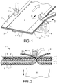
- FIGS 1 and 2 a part of the equipment for attaching a grip tab to the carrier layer of a film dressing in accordance with the preferred embodiment of the invention is schematically shown.
- the method according to the invention can easily be performed without sophisticated equipment and without influencing the normal production rate of film dressings.
- two continuous strips of heat weldable material 1,2 has been drawn from two rollers (not shown) and laid onto a film dressing web 3, the strips 1,2 extending along the two opposite edges thereof.
- Web 3 includes a film layer 4 having a thickness of 60 micrometer or less, which is coated with a layer of adhesive 5 on one side thereof.
- a carrier layer 6 is releasably attached to the film layer 4.
- a release layer 7 has also been applied covering the adhesive layer for protection thereof before use of the dressing.
- the film 4 is bought from a supplier it is usually delivered with a stiffening layer coextruded with the film during manufacture thereof.
- a stiffening layer makes it possible to handle the film during manufacture, storing and transport.
- Such a stiffening layer can to advantage be used as carrier layer in a film dressing but it is of course possible to substitute it with another layer.
- Such a carrier layer can be releasably attached to the film layer for example by application of heat and pressure or application of a suitable adhesive.
- the web3 and the applied strips 1,2 pass in the machine direction through a ultrasonic welding device, the machine direction illustrated by an arrow in figure 1 .
- the ultrasonic welding device is schematically shown in the figures by a horn 8 and counter rollers 9,10.
- the ultrasonic welding device cuts away the outermost portions of the film dressing web 3 and the applied strips 1,2 and simultaneously produces a weld seam WS along each of the cut edges.
- the strips 1,2 is thereby affixed to the carrier layer 6 with the outermost portion of each of the strips 1,2 and the seams WS coincident with the cut edge of the web 3.
- the counter rollers 9, 10 each have a circumferential flange 11 on their outermost sides.
- material located under the flange 11 will be subjected to a higher degree of mechanical deformation than the material located under the remaining part of the respective counter roller. Accordingly more heat will be produced in the material under the respective flange than in the material under the remaining part of the respective counter roller.
- the counter rollers are constructed so that the material under the flange part of the rollers will melt away so that a cutting occur while the material under the remaining part of the rollers will soften to such a degree that the strips 1,2 will fuse together with the carrier layer 6.
- the materials in layers 4 and 7 will also soften and in order to prevent fusing together of layers 6 and 4 and 4 and 7, these materials should be incompatible to each other from a welding point of view.
- the film layer 4 is preferably of polyurethane and the carrier layer 6 of polypropylene, materials which are incompatible to each other from a welding point of view, i.e. they do not fuse together when softened.
- the adhesive coating is preferably a silicone gel adhesive and the release layer 7 is preferably made of polyethylene. If another adhesive, for example an acrylate adhesive is used, a release layer of for example silicon coated paper, or silicone coated polyethylene could be used. If silicone coated paper is used as a release layer, this should be applied after the film dressing web has passed the ultrasonic welding device. In such a case, a process layer of thermoplastic material is applied to cover the adhesive coating until the film dressing web has passed the ultrasonic welding device in order to prevent adhesive from adhering to the horn of the ultrasonic welding device. This process layer is then substituted by the release paper layer. In order to facilitate the manufacturing process a release layer made of a thermoplastic material is preferred.
- the continuous strips 1,2 can be preferably be made of the same material as the carrier layer to assure good weldability there between but other materials, such as elastic polyolefin-based films, e.g. ethylene-vinyl-alcohol, having good weldability to the polypropylene in the carrier layer 6 can also be used.
- elastic polyolefin-based films e.g. ethylene-vinyl-alcohol
- thermoplastic materials for layers 4,6, 7and strips 1,2 having poor weldability to each other can also be used in the present invention.
- Polyester can for example be used as an alternative to polypropylene.
- distinct film dressings are made by cross-wise cutting of the web 3 and the applied grip tabs 1,2 and then be brought into neat packages in which the grip tabs are protected from wrinkling and other deformation due to packaging and later handling of the packages made.
- the grip tabs By such protection it is also ensured that the grip tabs not unintentionally can be gripped during handling of the package of film dressings, such unintentional gripping can lead to local release of the carrier layer from the film layer.
- the web 3 with the applied grip tabs 1,2 can be wound on a storage roller, thereby forming a film dressing of the type in which separate film dressings with a desired shape or dimension can be cut out by the user and still having at least one grip tab if at least a portion of one edge of the web 3 is present in the cut out film dressing.
- the film dressings made by cross-wise cutting of the web 3 can of course be cut into any desired shape.
- the grip tabs 1,2 extend along the total length of two opposite edge portions of the manufactured film dressing(s).
- continuous strips 1,2 apply a row of separate strips along each of the two opposite edges of the web 3, thereby obtaining grip tabs which only extend along a part of the length of the edges of the produced film dressings. It is of course also possible to only apply a strip along one of the two opposite sides of web 3, but this is not preferred.
- the width of the seam WS formed between a grip tab 1,2 and the carrier layer 6 should not exceed 1 mm in the produced film dressing and the inward extension of the grip tab 1,2 over the carrier layer should preferably be at least 10 mm to facilitate easy handling thereof.
- these can have different colour than the carrier layer or/and a different structure, for example obtained by embossing.
- the radial and axial dimensions of the counter rollers 9, 10 to obtain the desired weld seam and cutting line depend on the thickness of the material passing through the ultrasonic welding device, the type of thermoplastic materials involved, the transport rate of the web and the frequency of the ultra sonic horn.
- suitable counter rollers can easily be chosen or constructed by the skilled man on basis of desired values for the parameters mentioned above.
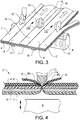
- FIGS 3 and 4 a second embodiment is schematically illustrated in views similar to figures 1 and 2 .
- This embodiment differs from the embodiment described with reference to figures 1 and 2 mainly in that the film dressing web is cut into two separate parts in order to produce film dressings having a transverse dimension smaller than the film dressing web 3' and in that grip tabs 15,16 are affixed to the adjacent edges of these two separate parts.
- Components in the embodiment according to figures 3 and 4 corresponding to similar components in the embodiment according to figures 1 and 2 are given the same reference numerals with the addition of a prime sign.
- a strip 12 is laid onto film dressing web 3' extending in the machine direction in the middle of film dressing web 3' simultaneously with strips 1' and 2' extending along the edges of web 3'.
- the web 3' with applied strips 1',2' and 12 is then passed through an ultrasound welding device having a horn 8' and counter rollers 9',10' and 13.
- the counter rollers 9',10' are similar to the counter rollers 9,10 described with reference to figures 1 and 2 whereas counter roller 13 differs from rollers 9',10' by having larger dimension in a transverse direction relative to the machine direction and by having the flange 14 located in the middle of the roller as seen in the transverse direction.
- the release layer 7' is built of three parts whereby grip tabs 17 and 18 are provided by bending the inner longitudinal edge portions of the two outer parts and by letting the opposite longitudinal edge portions of the middle part extend over said bents portions.
- grip tabs should of course be located outside of cutting lines made by the ultrasonic welding device.
- film dressings having the same transverse dimension are produced. However, it is possible to vary the transverse dimension of the produced film dressings by application of the strip 13 away from the middle of the film dressing web 3'.
- the counter roller of the ultrasound welding device are located on the same side as the strips attached to the carrier layer and the horn is located on the same side as the release layer. This is however not necessary, the method will function also if the counter rollers and horn changes locations.
- the film dressing web 3,3' have its carrier layer upwards but it is possible to produce this web and attach the strips with the web turned upside down in relation to the position shown in the drawings.
- the described embodiments of the method can be modified without leaving the scope of the invention.
- the portions of the strips extending inwards over the carrier layer need not have straight edges but can have curved edges, which is preferred if the grip tabs only extend along a part of the length of the edge of a produced dressing.
- the portions of strips may also be discreetly affixed to the film, i.e. not cover along the complete edge.
- the grip tab need not be present on both of two opposite sides of the carrier layer but can be present only on such edge. However, it is preferred that grip tabs are present on both of two opposite sides and if the film dressing web is divided into several parts this is a must.
- the scope of invention should therefore only be limited of the content of the enclosed patent claims.
Landscapes
- Health & Medical Sciences (AREA)
- Engineering & Computer Science (AREA)
- Life Sciences & Earth Sciences (AREA)
- Biomedical Technology (AREA)
- Heart & Thoracic Surgery (AREA)
- Vascular Medicine (AREA)
- Animal Behavior & Ethology (AREA)
- General Health & Medical Sciences (AREA)
- Public Health (AREA)
- Veterinary Medicine (AREA)
- Manufacturing & Machinery (AREA)
- Laminated Bodies (AREA)
- Absorbent Articles And Supports Therefor (AREA)
- Packages (AREA)
- Lining Or Joining Of Plastics Or The Like (AREA)
Claims (9)
- Procédé de fixation d'une languette de saisie (1, 2 ; 1', 2') à au moins l'un de deux bords opposés d'une couche de support détachable (6 ; 6') d'une nappe de pansement film (3 ; 3'), ladite nappe comprenant une couche de film (4 ; 4') sur une première face revêtue d'adhésif (5 ; 5') et une couche de support (6) fixée de manière détachable à la couche de film (4 ; 4') sur sa seconde face qui est opposée à la première face, la couche de film (4 ; 4') et la couche de support (6 ; 6') ayant les mêmes dimensions, caractérisé par les étapes suivantes :- choix pour la couche de support d'un matériau (6 ; 6') qui est incompatible avec la couche de film (4 ; 4') au niveau thermosoudure,- apport de ladite nappe de pansement film (3 ; 3') dans un sens de la machine,- application d'une bande de matériau (1, 2 ; 1', 2') compatible avec la couche de support (6 ; 6') au niveau thermosoudure le long d'au moins une partie d'une section de bordure d'au moins une des faces opposées de ladite nappe (3 ; 3') s'étendant parallèlement au sens de la machine, et- fixation de ladite au moins une bande (1, 2 ; 1', 2') sur la couche de support (6 ; 6') et sectionnement simultané d'une partie située le plus à l'extérieur de la nappe (3 ; 3') avec l'au moins une bande (1, 2 ; 1', 2') appliquée dessus en faisant passer la nappe avec l'au moins une bande appliquée dessus à travers un dispositif de soudage ultrasonique (8-10 ; 8'-10').
- Procédé selon la revendication 1, dans lequel l'au moins une bande de matériau (1, 2 ; 1', 2') est continue.
- Procédé selon la revendication 1 ou 2, dans lequel une couche de détachement en matériau thermoplastique (7, 7') est fixée au revêtement adhésif (5 ; 5') sur la couche de film (4 ; 4') avant l'étape d'application d'une bande de matériau (1, 2 ; 1', 2') sur la couche de support (6 ; 6').
- Procédé selon la revendication 1 ou 2, dans lequel, simultanément à l'application de la bande (1 ; 2') appliquée le long d'au moins une section de bordure d'au moins une des faces opposées de ladite nappe (3'), une ou plusieurs bandes (12) de matériau compatible avec la couche de support (6') au niveau thermosoudure sont appliquées entre les deux bords opposés de la couche de support (6') s'étendant parallèlement au sens de la machine et, simultanément à la fixation de la bande (1', 2'), appliquées le long d'au moins une section de bordure d'au moins une des faces opposées de ladite nappe, la ou les bandes appliquées entre les deux bords opposés de la couche de support (6') est ou sont fixées à la couche de support (6') et, simultanément à la fixations desdites bandes (12), ladite nappe de pansement film (3') est coupée en faisant passer la nappe (3') avec ladite ou lesdites bandes (12) appliquées dessus à travers un dispositif de soudage ultrasonique (8'-10'), la ligne de coupe dans chaque dite bande (12) appliquée entre les deux bords opposés de la couche de support (6') étant située entre les deux bords opposés de ladite bande (12) qui est parallèle au sens de la machine.
- Pansement film comprenant une couche de film (4) sur une première face revêtue d'adhésif (5), une couche de support (6) fixée de manière détachable sur la couche de film (4) sur sa seconde face étant opposée à la première face, et une couche de détachement (7) fixée de manière détachable au revêtement adhésif, la couche de film, la couche de support et la couche de détachement ayant les mêmes dimensions, caractérisé par une languette de saisie (1, 2) s'étendant vers l'intérieur au-dessus de la couche de support (6) depuis le premier bord du pansement et étant fixée à la couche de support (6) par une jointure (WS) dont la partie située le plus à l'extérieur est alignée avec ledit premier bord, la largeur de la jointure (WS) étant inférieure à 1 mm.
- Pansement film selon la revendication 5, dans lequel une languette de saisie (1, 2) s'étend vers l'intérieur au-dessus de la couche de support (6) et également depuis un souvent bord du pansement opposé au premier bord et est fixée à la couche de support par une jointure (WS) dont la partie située le plus à l'extérieur est alignée avec ledit second bord.
- Pansement film selon la revendication 5 ou 6, dans lequel chaque languette de saisie (1, 2) est composée du même matériau que la couche de support.
- Pansement film selon la revendication 5, 6, ou 7 dans lequel la couche de support (6) est composée de polypropylène et la couche de film (4) est composée de polyuréthane.
- Pansement film selon une ou plusieurs des revendications 5 à 8, dans lequel le revêtement adhésif (5) est à base d'adhésif au gel de silicone et la couche de détachement (7) est à base de polyéthylène.
Applications Claiming Priority (2)
| Application Number | Priority Date | Filing Date | Title |
|---|---|---|---|
| SE0950711 | 2009-09-30 | ||
| PCT/SE2010/050897 WO2011040860A1 (fr) | 2009-09-30 | 2010-08-19 | Procédé de fixation de languettes de saisie d'une couche de support de pansement film |
Publications (3)
| Publication Number | Publication Date |
|---|---|
| EP2482774A1 EP2482774A1 (fr) | 2012-08-08 |
| EP2482774A4 EP2482774A4 (fr) | 2014-05-28 |
| EP2482774B1 true EP2482774B1 (fr) | 2018-01-31 |
Family
ID=43826511
Family Applications (1)
| Application Number | Title | Priority Date | Filing Date |
|---|---|---|---|
| EP10820900.8A Active EP2482774B1 (fr) | 2009-09-30 | 2010-08-19 | Procédé de fixation de languettes de saisie d'une couche de support de pansement film |
Country Status (8)
| Country | Link |
|---|---|
| US (1) | US9486366B2 (fr) |
| EP (1) | EP2482774B1 (fr) |
| JP (1) | JP5624147B2 (fr) |
| CN (1) | CN102573721B (fr) |
| AU (1) | AU2010301154B2 (fr) |
| CA (1) | CA2771801C (fr) |
| IN (1) | IN2012DN01772A (fr) |
| WO (1) | WO2011040860A1 (fr) |
Cited By (1)
| Publication number | Priority date | Publication date | Assignee | Title |
|---|---|---|---|---|
| WO2018162477A3 (fr) * | 2017-03-09 | 2019-01-17 | Lithium Energy and Power GmbH & Co. KG | Procédé de soudage par ultrasons de séparateurs |
Families Citing this family (5)
| Publication number | Priority date | Publication date | Assignee | Title |
|---|---|---|---|---|
| US9486366B2 (en) | 2009-09-30 | 2016-11-08 | Mölnlycke Health Care Ab | Method of attaching grip tabs to the carrier layer of a film dressing |
| US8697118B2 (en) * | 2011-10-18 | 2014-04-15 | St. Teresa Medical, Inc. | Stabilizers for hemostatic products |
| CN105287440A (zh) * | 2014-06-18 | 2016-02-03 | 杨宁正 | 渗透式药用薄膜贴片 |
| CA3004734A1 (fr) | 2015-11-12 | 2017-06-18 | St. Teresa Medical, Inc. | Procede de scellement d'une durotomie |
| WO2019089717A1 (fr) | 2017-11-02 | 2019-05-09 | St. Teresa Medical, Inc. | Produits de scellement à base de fibrine |
Family Cites Families (34)
| Publication number | Priority date | Publication date | Assignee | Title |
|---|---|---|---|---|
| GB791267A (en) | 1956-05-10 | 1958-02-26 | Scholl Mfg Co Ltd | Improvements in and relating to methods of and apparatus for manufacturing adhesive materials, and to adhesive materials |
| US3118031A (en) * | 1961-03-21 | 1964-01-14 | Cutler Hammer Inc | Treadle switch |
| NL134948C (fr) * | 1963-03-05 | 1900-01-01 | ||
| GB1095428A (fr) * | 1965-05-15 | |||
| US4545371A (en) | 1980-09-11 | 1985-10-08 | American Hospital Supply Corporation | System and method for bandaging a patient |
| CA1180244A (fr) | 1981-06-10 | 1985-01-02 | Jerome D. Muchin | Systeme distributeur de pansements de copolymer enduits d'adhesif |
| US4485809A (en) | 1981-12-11 | 1984-12-04 | Johnson & Johnson Products, Inc. | Film window dressing |
| GB2157958A (en) * | 1984-05-03 | 1985-11-06 | Ernest Edward Austen Bedding | Ball game net support |
| US4600001A (en) | 1984-08-15 | 1986-07-15 | The Kendall Company | Combined wound dressing and delivery means composite |
| US4598004A (en) | 1985-01-24 | 1986-07-01 | Minnesota Mining And Manufacturing Company | Thin film surgical dressing with delivery system |
| US4884563A (en) * | 1985-03-01 | 1989-12-05 | Ferris Mfg. Corp. | Non-stretching wound dressing and method for making same |
| NO894195L (no) | 1989-06-05 | 1990-12-06 | Bertek Inc | Anordning for paafoering av en tynn film. |
| US5160315A (en) * | 1991-04-05 | 1992-11-03 | Minnesota Mining And Manufacturing Company | Combined adhesive strip and transparent dressing delivery system |
| FR2690617B1 (fr) * | 1992-04-29 | 1994-06-24 | Cbh Textile | Pansement adhesif transparent. |
| ES2150984T3 (es) * | 1993-03-22 | 2000-12-16 | Minnesota Mining & Mfg | Apositos suministrados a partir de una estructura de bastidor y metodo de fabricacion. |
| DE4314834C2 (de) * | 1993-05-05 | 1998-04-30 | Beiersdorf Ag | Verbandmaterial auf Folienbasis |
| SE501470C2 (sv) * | 1993-06-28 | 1995-02-20 | Moelnlycke Ab | Förfarande för att tillverka artiklar, såsom kompresser, operationskompresser eller liknande, samt medelst förfarandet tillverkad artikel |
| WO1996019205A1 (fr) * | 1994-12-21 | 1996-06-27 | Theratech, Inc. | Systeme de liberation transdermique avec opercule adhesif et rondelle pelable |
| DE29511224U1 (de) | 1995-07-11 | 1995-10-26 | Textilma Ag, Hergiswil | Ultraschallvorrichtung zum Schneiden einer schmelzfähigen Textilbahn und gleichzeitigen Verschweißen der Schnittränder |
| GB9621921D0 (en) * | 1996-10-22 | 1996-12-18 | Innovative Tech Ltd | Film delivery assembly |
| SE510799C2 (sv) * | 1997-05-20 | 1999-06-21 | Moelnlycke Health Care Ab | Absorberande flerskiktsmaterial samt förfarande och anordning för att tillverka ett sådant |
| DE19841550A1 (de) * | 1998-09-11 | 2000-03-23 | Beiersdorf Ag | Verbandmaterial auf Folienbasis |
| SE9804268L (sv) * | 1998-12-09 | 2000-03-27 | Moelnlycke Health Care Ab | Förfarande för att tillverka ett greppflikförsett skyddsskikt för adhesiva ytor |
| US7049479B2 (en) * | 2002-02-07 | 2006-05-23 | Corium Corporation | Ultra thin film transdermal/dermal or transmucosal/mucosal delivery system |
| JP2004051914A (ja) | 2002-07-24 | 2004-02-19 | Lintec Corp | 積層シートおよびその製造方法 |
| US20040143220A1 (en) * | 2003-01-17 | 2004-07-22 | George Worthley | Wound and catheter dressing and a method for making and applying a dressing |
| CN2714025Y (zh) * | 2004-02-16 | 2005-08-03 | 王文 | 一种新型的创口贴 |
| GB0417043D0 (en) * | 2004-07-30 | 2004-09-01 | Stanelco Fibre Optics Ltd | Forming enclosures |
| JP2008220395A (ja) * | 2007-03-08 | 2008-09-25 | Aso Seiyaku Kk | 救急絆創膏包装体 |
| JP5036385B2 (ja) | 2007-04-19 | 2012-09-26 | 日東電工株式会社 | フィルムドレッシング |
| US20090105670A1 (en) | 2007-10-23 | 2009-04-23 | Boehringer Technologies, L.P. | Thin film wound cover, suction assisted wound treatment system using the same, method of using the thin film wound cover and method of making the same |
| SE532495C2 (sv) * | 2007-12-13 | 2010-02-09 | Moelnlycke Health Care Ab | Förband för att skydda huden kring föremål som skjuter ut därifrån |
| EP2456839A1 (fr) * | 2009-07-21 | 2012-05-30 | Mylan Inc. | Procédé de fabrication en continu d'un tampon transdermique à base de polyisobutylène |
| US9486366B2 (en) | 2009-09-30 | 2016-11-08 | Mölnlycke Health Care Ab | Method of attaching grip tabs to the carrier layer of a film dressing |
-
2010
- 2010-08-19 US US13/498,593 patent/US9486366B2/en active Active
- 2010-08-19 WO PCT/SE2010/050897 patent/WO2011040860A1/fr active Application Filing
- 2010-08-19 CN CN201080042849.5A patent/CN102573721B/zh active Active
- 2010-08-19 AU AU2010301154A patent/AU2010301154B2/en not_active Ceased
- 2010-08-19 EP EP10820900.8A patent/EP2482774B1/fr active Active
- 2010-08-19 JP JP2012532044A patent/JP5624147B2/ja not_active Expired - Fee Related
- 2010-08-19 CA CA2771801A patent/CA2771801C/fr not_active Expired - Fee Related
-
2012
- 2012-02-28 IN IN1772DEN2012 patent/IN2012DN01772A/en unknown
Non-Patent Citations (1)
| Title |
|---|
| None * |
Cited By (1)
| Publication number | Priority date | Publication date | Assignee | Title |
|---|---|---|---|---|
| WO2018162477A3 (fr) * | 2017-03-09 | 2019-01-17 | Lithium Energy and Power GmbH & Co. KG | Procédé de soudage par ultrasons de séparateurs |
Also Published As
| Publication number | Publication date |
|---|---|
| AU2010301154A1 (en) | 2012-04-12 |
| WO2011040860A1 (fr) | 2011-04-07 |
| US9486366B2 (en) | 2016-11-08 |
| CN102573721B (zh) | 2015-09-09 |
| IN2012DN01772A (fr) | 2015-06-05 |
| CN102573721A (zh) | 2012-07-11 |
| AU2010301154B2 (en) | 2016-02-25 |
| JP2013506492A (ja) | 2013-02-28 |
| US20120184891A1 (en) | 2012-07-19 |
| EP2482774A1 (fr) | 2012-08-08 |
| CA2771801A1 (fr) | 2011-04-07 |
| JP5624147B2 (ja) | 2014-11-12 |
| CA2771801C (fr) | 2017-03-28 |
| EP2482774A4 (fr) | 2014-05-28 |
Similar Documents
| Publication | Publication Date | Title |
|---|---|---|
| EP2482774B1 (fr) | Procédé de fixation de languettes de saisie d'une couche de support de pansement film | |
| US11014729B2 (en) | Multi-layer web and process for forming scored lidding film for blister packages | |
| US20120052230A1 (en) | Method of manufacturing a film dressing | |
| JPS61164926A (ja) | 包装、包装積層材料および包装方法 | |
| JPH04112053U (ja) | パツケージ材 | |
| KR20100097131A (ko) | 컷 테이프 및 컷 테이프가 부착된 포장 주머니 | |
| JP2009227319A (ja) | 咬合具付包装袋 | |
| US20050220377A1 (en) | Tear string opening system for flexible container | |
| US20130308882A1 (en) | Easy-open peel pouch | |
| JP3141892U (ja) | カートン積層体 | |
| JP6599660B2 (ja) | 巻付けラベル連続体の製造方法、及びラベル付き容器 | |
| EP1871690B1 (fr) | Ruban de materiau d'emballage | |
| JP4635064B2 (ja) | 粘着性被覆体の製造装置 | |
| EP1164997A1 (fr) | Procede de fabrication d'une feuille de protection de surface adhesive comportant une languette de saisie | |
| KR100947370B1 (ko) | 일회용 장갑, 일회용 장갑 제조 장치 및 그 제조 방법 | |
| CN104050871A (zh) | 一种不干胶标签带的生产方法 | |
| JP7426707B2 (ja) | 製袋業者用の帯状フィルム製造方法 | |
| US20240286818A1 (en) | Packaging bag and manufacturing system thereof | |
| EP3515836B1 (fr) | Film d'emballage comprenant une couche supérieure formant une piste d'ouverture prédéfinie | |
| JP2022138466A (ja) | 紙製チューブ状容器 | |
| JP2023042036A (ja) | 容器用包装体および容器用包装体原反 | |
| JP3833008B2 (ja) | 梱包用バンドコイルユニット | |
| KR20210100682A (ko) | 필름 및 파우치 | |
| CN104085172B (zh) | 一种不干胶标签带的制造方法 | |
| JP2014051300A (ja) | 台紙なしラベルの包装方法およびそのロールセット |
Legal Events
| Date | Code | Title | Description |
|---|---|---|---|
| PUAI | Public reference made under article 153(3) epc to a published international application that has entered the european phase |
Free format text: ORIGINAL CODE: 0009012 |
|
| 17P | Request for examination filed |
Effective date: 20120319 |
|
| AK | Designated contracting states |
Kind code of ref document: A1 Designated state(s): AL AT BE BG CH CY CZ DE DK EE ES FI FR GB GR HR HU IE IS IT LI LT LU LV MC MK MT NL NO PL PT RO SE SI SK SM TR |
|
| DAX | Request for extension of the european patent (deleted) | ||
| A4 | Supplementary search report drawn up and despatched |
Effective date: 20140429 |
|
| RIC1 | Information provided on ipc code assigned before grant |
Ipc: A61F 13/02 20060101AFI20140423BHEP Ipc: A61F 13/00 20060101ALI20140423BHEP |
|
| GRAP | Despatch of communication of intention to grant a patent |
Free format text: ORIGINAL CODE: EPIDOSNIGR1 |
|
| RIC1 | Information provided on ipc code assigned before grant |
Ipc: A61F 13/02 20060101AFI20170821BHEP Ipc: A61F 13/00 20060101ALI20170821BHEP |
|
| INTG | Intention to grant announced |
Effective date: 20170919 |
|
| GRAS | Grant fee paid |
Free format text: ORIGINAL CODE: EPIDOSNIGR3 |
|
| GRAA | (expected) grant |
Free format text: ORIGINAL CODE: 0009210 |
|
| AK | Designated contracting states |
Kind code of ref document: B1 Designated state(s): AL AT BE BG CH CY CZ DE DK EE ES FI FR GB GR HR HU IE IS IT LI LT LU LV MC MK MT NL NO PL PT RO SE SI SK SM TR |
|
| REG | Reference to a national code |
Ref country code: GB Ref legal event code: FG4D Ref country code: CH Ref legal event code: EP |
|
| REG | Reference to a national code |
Ref country code: AT Ref legal event code: REF Ref document number: 966683 Country of ref document: AT Kind code of ref document: T Effective date: 20180215 |
|
| REG | Reference to a national code |
Ref country code: IE Ref legal event code: FG4D |
|
| REG | Reference to a national code |
Ref country code: DE Ref legal event code: R096 Ref document number: 602010048365 Country of ref document: DE |
|
| REG | Reference to a national code |
Ref country code: SE Ref legal event code: TRGR |
|
| REG | Reference to a national code |
Ref country code: NL Ref legal event code: MP Effective date: 20180131 |
|
| REG | Reference to a national code |
Ref country code: LT Ref legal event code: MG4D |
|
| REG | Reference to a national code |
Ref country code: AT Ref legal event code: MK05 Ref document number: 966683 Country of ref document: AT Kind code of ref document: T Effective date: 20180131 |
|
| REG | Reference to a national code |
Ref country code: FR Ref legal event code: PLFP Year of fee payment: 9 |
|
| PG25 | Lapsed in a contracting state [announced via postgrant information from national office to epo] |
Ref country code: FI Free format text: LAPSE BECAUSE OF FAILURE TO SUBMIT A TRANSLATION OF THE DESCRIPTION OR TO PAY THE FEE WITHIN THE PRESCRIBED TIME-LIMIT Effective date: 20180131 Ref country code: NO Free format text: LAPSE BECAUSE OF FAILURE TO SUBMIT A TRANSLATION OF THE DESCRIPTION OR TO PAY THE FEE WITHIN THE PRESCRIBED TIME-LIMIT Effective date: 20180430 Ref country code: LT Free format text: LAPSE BECAUSE OF FAILURE TO SUBMIT A TRANSLATION OF THE DESCRIPTION OR TO PAY THE FEE WITHIN THE PRESCRIBED TIME-LIMIT Effective date: 20180131 Ref country code: NL Free format text: LAPSE BECAUSE OF FAILURE TO SUBMIT A TRANSLATION OF THE DESCRIPTION OR TO PAY THE FEE WITHIN THE PRESCRIBED TIME-LIMIT Effective date: 20180131 Ref country code: ES Free format text: LAPSE BECAUSE OF FAILURE TO SUBMIT A TRANSLATION OF THE DESCRIPTION OR TO PAY THE FEE WITHIN THE PRESCRIBED TIME-LIMIT Effective date: 20180131 Ref country code: HR Free format text: LAPSE BECAUSE OF FAILURE TO SUBMIT A TRANSLATION OF THE DESCRIPTION OR TO PAY THE FEE WITHIN THE PRESCRIBED TIME-LIMIT Effective date: 20180131 |
|
| PG25 | Lapsed in a contracting state [announced via postgrant information from national office to epo] |
Ref country code: PL Free format text: LAPSE BECAUSE OF FAILURE TO SUBMIT A TRANSLATION OF THE DESCRIPTION OR TO PAY THE FEE WITHIN THE PRESCRIBED TIME-LIMIT Effective date: 20180131 Ref country code: AT Free format text: LAPSE BECAUSE OF FAILURE TO SUBMIT A TRANSLATION OF THE DESCRIPTION OR TO PAY THE FEE WITHIN THE PRESCRIBED TIME-LIMIT Effective date: 20180131 Ref country code: GR Free format text: LAPSE BECAUSE OF FAILURE TO SUBMIT A TRANSLATION OF THE DESCRIPTION OR TO PAY THE FEE WITHIN THE PRESCRIBED TIME-LIMIT Effective date: 20180501 Ref country code: BG Free format text: LAPSE BECAUSE OF FAILURE TO SUBMIT A TRANSLATION OF THE DESCRIPTION OR TO PAY THE FEE WITHIN THE PRESCRIBED TIME-LIMIT Effective date: 20180430 Ref country code: IS Free format text: LAPSE BECAUSE OF FAILURE TO SUBMIT A TRANSLATION OF THE DESCRIPTION OR TO PAY THE FEE WITHIN THE PRESCRIBED TIME-LIMIT Effective date: 20180531 Ref country code: LV Free format text: LAPSE BECAUSE OF FAILURE TO SUBMIT A TRANSLATION OF THE DESCRIPTION OR TO PAY THE FEE WITHIN THE PRESCRIBED TIME-LIMIT Effective date: 20180131 |
|
| PG25 | Lapsed in a contracting state [announced via postgrant information from national office to epo] |
Ref country code: AL Free format text: LAPSE BECAUSE OF FAILURE TO SUBMIT A TRANSLATION OF THE DESCRIPTION OR TO PAY THE FEE WITHIN THE PRESCRIBED TIME-LIMIT Effective date: 20180131 Ref country code: RO Free format text: LAPSE BECAUSE OF FAILURE TO SUBMIT A TRANSLATION OF THE DESCRIPTION OR TO PAY THE FEE WITHIN THE PRESCRIBED TIME-LIMIT Effective date: 20180131 Ref country code: EE Free format text: LAPSE BECAUSE OF FAILURE TO SUBMIT A TRANSLATION OF THE DESCRIPTION OR TO PAY THE FEE WITHIN THE PRESCRIBED TIME-LIMIT Effective date: 20180131 Ref country code: IT Free format text: LAPSE BECAUSE OF FAILURE TO SUBMIT A TRANSLATION OF THE DESCRIPTION OR TO PAY THE FEE WITHIN THE PRESCRIBED TIME-LIMIT Effective date: 20180131 |
|
| REG | Reference to a national code |
Ref country code: DE Ref legal event code: R097 Ref document number: 602010048365 Country of ref document: DE |
|
| PG25 | Lapsed in a contracting state [announced via postgrant information from national office to epo] |
Ref country code: CZ Free format text: LAPSE BECAUSE OF FAILURE TO SUBMIT A TRANSLATION OF THE DESCRIPTION OR TO PAY THE FEE WITHIN THE PRESCRIBED TIME-LIMIT Effective date: 20180131 Ref country code: SM Free format text: LAPSE BECAUSE OF FAILURE TO SUBMIT A TRANSLATION OF THE DESCRIPTION OR TO PAY THE FEE WITHIN THE PRESCRIBED TIME-LIMIT Effective date: 20180131 Ref country code: DK Free format text: LAPSE BECAUSE OF FAILURE TO SUBMIT A TRANSLATION OF THE DESCRIPTION OR TO PAY THE FEE WITHIN THE PRESCRIBED TIME-LIMIT Effective date: 20180131 Ref country code: SK Free format text: LAPSE BECAUSE OF FAILURE TO SUBMIT A TRANSLATION OF THE DESCRIPTION OR TO PAY THE FEE WITHIN THE PRESCRIBED TIME-LIMIT Effective date: 20180131 |
|
| PLBE | No opposition filed within time limit |
Free format text: ORIGINAL CODE: 0009261 |
|
| STAA | Information on the status of an ep patent application or granted ep patent |
Free format text: STATUS: NO OPPOSITION FILED WITHIN TIME LIMIT |
|
| 26N | No opposition filed |
Effective date: 20181102 |
|
| PG25 | Lapsed in a contracting state [announced via postgrant information from national office to epo] |
Ref country code: SI Free format text: LAPSE BECAUSE OF FAILURE TO SUBMIT A TRANSLATION OF THE DESCRIPTION OR TO PAY THE FEE WITHIN THE PRESCRIBED TIME-LIMIT Effective date: 20180131 |
|
| PG25 | Lapsed in a contracting state [announced via postgrant information from national office to epo] |
Ref country code: MC Free format text: LAPSE BECAUSE OF FAILURE TO SUBMIT A TRANSLATION OF THE DESCRIPTION OR TO PAY THE FEE WITHIN THE PRESCRIBED TIME-LIMIT Effective date: 20180131 |
|
| REG | Reference to a national code |
Ref country code: CH Ref legal event code: PL |
|
| PG25 | Lapsed in a contracting state [announced via postgrant information from national office to epo] |
Ref country code: LI Free format text: LAPSE BECAUSE OF NON-PAYMENT OF DUE FEES Effective date: 20180831 Ref country code: CH Free format text: LAPSE BECAUSE OF NON-PAYMENT OF DUE FEES Effective date: 20180831 Ref country code: LU Free format text: LAPSE BECAUSE OF NON-PAYMENT OF DUE FEES Effective date: 20180819 |
|
| REG | Reference to a national code |
Ref country code: BE Ref legal event code: MM Effective date: 20180831 |
|
| REG | Reference to a national code |
Ref country code: IE Ref legal event code: MM4A |
|
| PG25 | Lapsed in a contracting state [announced via postgrant information from national office to epo] |
Ref country code: IE Free format text: LAPSE BECAUSE OF NON-PAYMENT OF DUE FEES Effective date: 20180819 |
|
| PG25 | Lapsed in a contracting state [announced via postgrant information from national office to epo] |
Ref country code: BE Free format text: LAPSE BECAUSE OF NON-PAYMENT OF DUE FEES Effective date: 20180831 |
|
| PG25 | Lapsed in a contracting state [announced via postgrant information from national office to epo] |
Ref country code: MT Free format text: LAPSE BECAUSE OF NON-PAYMENT OF DUE FEES Effective date: 20180819 |
|
| PG25 | Lapsed in a contracting state [announced via postgrant information from national office to epo] |
Ref country code: TR Free format text: LAPSE BECAUSE OF FAILURE TO SUBMIT A TRANSLATION OF THE DESCRIPTION OR TO PAY THE FEE WITHIN THE PRESCRIBED TIME-LIMIT Effective date: 20180131 |
|
| PG25 | Lapsed in a contracting state [announced via postgrant information from national office to epo] |
Ref country code: HU Free format text: LAPSE BECAUSE OF FAILURE TO SUBMIT A TRANSLATION OF THE DESCRIPTION OR TO PAY THE FEE WITHIN THE PRESCRIBED TIME-LIMIT; INVALID AB INITIO Effective date: 20100819 Ref country code: PT Free format text: LAPSE BECAUSE OF FAILURE TO SUBMIT A TRANSLATION OF THE DESCRIPTION OR TO PAY THE FEE WITHIN THE PRESCRIBED TIME-LIMIT Effective date: 20180131 |
|
| PG25 | Lapsed in a contracting state [announced via postgrant information from national office to epo] |
Ref country code: CY Free format text: LAPSE BECAUSE OF FAILURE TO SUBMIT A TRANSLATION OF THE DESCRIPTION OR TO PAY THE FEE WITHIN THE PRESCRIBED TIME-LIMIT Effective date: 20180131 Ref country code: MK Free format text: LAPSE BECAUSE OF NON-PAYMENT OF DUE FEES Effective date: 20180131 |
|
| PGFP | Annual fee paid to national office [announced via postgrant information from national office to epo] |
Ref country code: SE Payment date: 20230710 Year of fee payment: 14 |
|
| PGFP | Annual fee paid to national office [announced via postgrant information from national office to epo] |
Ref country code: DE Payment date: 20240828 Year of fee payment: 15 |
|
| PGFP | Annual fee paid to national office [announced via postgrant information from national office to epo] |
Ref country code: GB Payment date: 20240827 Year of fee payment: 15 |
|
| PGFP | Annual fee paid to national office [announced via postgrant information from national office to epo] |
Ref country code: FR Payment date: 20240826 Year of fee payment: 15 |