EP2482091A1 - Verfahren zur Inspektion des Motorzustands und Vorrichtung zur Inspektion der Motoreigenschaften - Google Patents
Verfahren zur Inspektion des Motorzustands und Vorrichtung zur Inspektion der Motoreigenschaften Download PDFInfo
- Publication number
- EP2482091A1 EP2482091A1 EP12275005A EP12275005A EP2482091A1 EP 2482091 A1 EP2482091 A1 EP 2482091A1 EP 12275005 A EP12275005 A EP 12275005A EP 12275005 A EP12275005 A EP 12275005A EP 2482091 A1 EP2482091 A1 EP 2482091A1
- Authority
- EP
- European Patent Office
- Prior art keywords
- motor
- phase
- angular range
- counter electromotive
- variation
- Prior art date
- Legal status (The legal status is an assumption and is not a legal conclusion. Google has not performed a legal analysis and makes no representation as to the accuracy of the status listed.)
- Granted
Links
Images



Classifications
-
- G—PHYSICS
- G01—MEASURING; TESTING
- G01R—MEASURING ELECTRIC VARIABLES; MEASURING MAGNETIC VARIABLES
- G01R31/00—Arrangements for testing electric properties; Arrangements for locating electric faults; Arrangements for electrical testing characterised by what is being tested not provided for elsewhere
- G01R31/34—Testing dynamo-electric machines
-
- G—PHYSICS
- G01—MEASURING; TESTING
- G01R—MEASURING ELECTRIC VARIABLES; MEASURING MAGNETIC VARIABLES
- G01R31/00—Arrangements for testing electric properties; Arrangements for locating electric faults; Arrangements for electrical testing characterised by what is being tested not provided for elsewhere
- G01R31/34—Testing dynamo-electric machines
- G01R31/343—Testing dynamo-electric machines in operation
Definitions
- the present invention relates to a motor condition inspection method and a motor characteristic inspecting device for a motor that generates counter electromotive forces (counter electromotive voltages) when a mover of the motor is moved by an external force.
- the installation condition of a mover and a stator affects the output of the motor.
- a gap gauge is inserted into a gap formed between the mover and the stator to mechanically measure the size of the gap in order to inspect the installation condition.
- inspection is performed with the motor removed from the apparatus, and thus a mechanical error may occasionally occur when the motor is reinstalled in the apparatus after the inspection.
- the inventors invented a motor condition inspection method and a motor characteristic inspecting device allowing inspection of the characteristics of a motor by computing a counter electromotive force constant based on the frequency value and the amplitude value of the waveform of a counter electromotive force generated when the motor is moved by an external force (Refer to Japanese Patent Application No. 2009-177091 ).
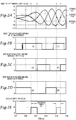
- the frequency is detected based on half the cycle of the counter electromotive voltage (corresponding to an electrical angle of 180°). If abrupt variations (abrupt variations in speed for a linear motor, and abrupt variations in number of revolutions for a rotary motor) are caused in half the cycle of the counter electromotive voltage during acceleration or deceleration, the duty ratio of the frequency before and after a peak value of the voltage may significantly vary, which tends to cause an error in the inspection results. For example, as shown in Fig.
- the duty ratio (f 1A : f 1B ) of the frequency is significantly varied in a time segment (A), which increases the possibility of an error compared to a time segment (B) in which the duty ratio (f 2A : f 2B ) of the frequency is not significantly varied.
- An object of the present invention is to provide a motor condition inspection method and a motor characteristic inspecting device that allow inspection of a motor installed in an apparatus without removing the motor from the apparatus and that reduce the possibility of an error in the inspection results.
- Another object of the present invention is to provide a motor condition inspection method and a motor characteristic inspecting device that make it possible to conveniently inspect whether or not a motor is properly installed.
- the present invention is directed to a motor condition inspection method and a motor characteristic inspecting device allowing inspection of the condition of a three-phase motor installed in an apparatus without removing the three-phase motor from the apparatus.
- a motor has a power generating function.
- counter electromotive forces counter electromotive voltages
- Ke ⁇ a counter electromotive force constant
- the present invention provides a motor characteristic inspecting device including: an angular range detecting section configured to detect a predetermined angular range including a peak value of a counter electromotive force for one phase among counter electromotive forces for three phases generated in armature windings of the three-phase motor when a mover of the three-phase motor is moved with no power supply, the predetermined angular range being less than 180° in terms of electrical angle; a three-phase-to-two-phase converting section configured to convert the counter electromotive forces for three phases into a two-phase AC voltage equivalent to the counter electromotive forces for three phases through ⁇ conversion such that ⁇ , axis indicates the counter electromotive force for one phase; a vector variation computing section configured to compute a voltage vector variation amount which is an amount of variation in voltage vector in the predetermined angular range, based on an amount of variation in ⁇ component and an amount of variation in ⁇ component in the predetermined angular range; a speed variation detecting section configured to detect a speed variation amount which is
- the motor characteristic inspecting device can calculate variations in speed that occur when the mover is moved by an external force over a predetermined angular range that is smaller than 180° in terms of electrical angle and the amount of increase in counter electromotive forces due to the variations in speed, as the voltage vector variation amount.
- the counter electromotive force constant calculated based on the voltage vector variation amount calculated as described above is subjected to a smaller error, even during acceleration or deceleration, than that for a counter electromotive force constant calculated based on the amount of variation in counter electromotive voltages.
- voltage vector used herein refers to a vector having ⁇ component and ⁇ component obtained by performing a three-phase-to-two-phase conversion on the components of the counter electromotive forces for three phases.
- the angular range detecting section may determine the predetermined angular range by various methods.
- the angular range detecting section may be configured to detect zero crossing points at which the counter electromotive forces for three phases become zero, and to determine the predetermined angular range based on the zero crossing points. In this case, an angular range of 60° may be determined as the predetermined angular range.
- the angular range detecting section may be configured to detect zero crossing points at which the counter electromotive forces for three phases and the two-phase AC voltage become zero, and to determine the predetermined angular range based on the zero crossing points. In this case, an angular range of 30° may be determined as the predetermined angular range.
- a smaller angular range that is smaller than 180° in terms of electrical angle results in a smaller amount of variation in voltage vector, and hence in a smaller error in the counter electromotive force constant. Therefore, the error in the counter electromotive force constant can be reduced by determining the counter electromotive force constant for an angular range of 30° than by determining the counter electromotive force constant for an angular range of 60°.
- the voltage vector variation amount ⁇ V vec may be considered as the magnitude of the difference between the first voltage vector and the second voltage vector.
- the error in the computed counter electromotive force constant can be reduced even if abrupt variations in speed occur.
- the result display section may be configured to display the computed result or the indication for the computed result if a difference between two voltage vector variation amounts for two divided angular ranges obtained by bisecting the predetermined angular range is equal to or smaller than a predetermined allowable value. If the difference between the two voltage vector variation amounts is larger than the predetermined allowable value, abrupt variations in speed are occurring, which tends to cause a significant error in the computed counter electromotive force constant.
- the reliability of the inspection results obtained by the present invention can be improved by causing the result display section to display the computed result or the indication for the computed result only when the difference is equal to or smaller than the allowable value.
- the motor to be inspected by the present invention may be any three-phase motor, whether a three-phase rotary motor or a linear motor, that allows detection of counter electromotive forces. If the three-phase motor is a three-phase rotary motor in which the mover is rotatable, the speed variation detecting section may be configured to detect the number of revolutions per unit time made by the mover as the speed, and to identify an amount of variation in the number of revolutions as the speed variation amount.
- the motor characteristic inspecting device may further include an installation condition determining section configured to determine a size of a gap between a magnetic pole provided in the stator and a magnetic pole provided in the mover based on the computed result from the constant computing section to determine whether or not the three-phase motor is properly installed based on the determined gap size. Because the gap size and the counter electromotive force constant are proportional to each other, it is possible to know the gap size in the linear motor installed in the apparatus by utilizing such proportional relationship, thereby determining the installation condition of the motor.
- stator and the mover of a linear motor are separately formed, and assembled together at the location of use. That is, motor installation and gap adjustment are often performed by a user. Therefore, gap adjustment may not be adequately performed using a gap gauge, as a result of which a sufficient output of the linear motor may not be obtained.
- gap adjustment can be easily performed.
- the installation condition determining section for a linear motor is configured to determine that the gap size exceeds an appropriate range if the counter electromotive force constant falls below a predetermined threshold range and that the gap size falls below the appropriate range if the counter electromotive force constant exceeds the predetermined threshold range, and to determine that the three-phase motor is not properly installed in either case.
- This configuration further facilitates gap adjustment.
- the present invention also provides a motor condition inspection method including: preparing the motor characteristic inspecting device according to the present invention; electrically connecting the armature windings and the motor characteristic inspecting device with power supply lines disconnected from the three-phase motor installed in the apparatus; applying an external force to the mover of the three-phase motor to generate the counter electromotive forces in the armature windings; and determining a condition of the three-phase motor based on the computed result displayed on the result display section of the motor characteristic inspecting device.
- the result display section displays the computed result (a numerical value) for the counter electromotive force constant, which allows a measurer to determine whether or not the obtained counter electromotive force constant is proper for the motor.
- the result display section may display a predetermined indication for an expected computed result of the counter electromotive force constant. This configuration facilitates determining whether or not the characteristics of the motor are proper even if the counter electromotive force constant of the motor is not readily available.
- Fig. 1 is a block diagram showing a motor characteristic inspecting device according to first embodiment of the present invention.
- a motor characteristic inspecting device 1 is connected to a three-phase rotary motor 3 to be inspected.
- the three-phase rotary motor 3 includes a stator 3a fixed to an apparatus and a mover 3b formed by a rotor that is rotatable, and has three phases, namely U-phase, V-phase, and W-phase.
- the motor to be inspected is disconnected from the power supply lines, and the motor characteristic inspecting device 1 is connected via a cable 7 to power supply lines 5 which are connected to the armature windings of the stator 3a.
- the motor characteristic inspecting device 1 is basically formed by a voltage measuring section 11, a three-phase-to-two-phase converting section 13, an electrical angle acquiring section 14, a computing section 20, and a result display section 27.
- the voltage measuring section 11 receives counter electromotive forces for three phases generated when the three-phase rotary motor 3 is moved by an external force, and measures and stores the voltage values (K eu , K ev , and K ew ) for U-phase, V-phase, and W-phase.
- the three-phase-to-two-phase converting section 13 reads from the voltage measuring section 11 the U-phase voltage value K eu and the V-phase voltage value K ev at times t 1 and t 2 , and performs a three-phase-to-two-phase conversion on the read voltage values.
- the counter electromotive forces for three phases are converted into a two-phase AC voltage equivalent to the counter electromotive forces for three phases through ⁇ conversion such that ⁇ axis indicates the counter electromotive force for U-phase.
- V vec voltage vector
- V ⁇ and V ⁇ stand for ⁇ component and ⁇ component, respectively, of the voltage vector.
- the three-phase-to-two-phase converting section 13 outputs ⁇ component V ⁇ and ⁇ component V ⁇ of the voltage vector to a vector variation computing section 23.
- the three-phase-to-two-phase conversion can be performed using only the U-phase voltage value K eu and the V-phase voltage value K ev , among the voltage values for three phases, as discussed later, and therefore the W-phase voltage value K ew is not read.
- the electrical angle acquiring section 14 is formed by a zero crossing detecting section 15, an angular range detecting section 17, and a constant pulse generating section 19.
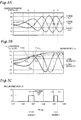
- the zero crossing detecting section 15 includes a U-phase zero crossing detecting section 15a, a V-phase zero crossing detecting section 15b, and a W-phase zero crossing detecting section 15c, and is configured to output a voltage whose value changes from 0 V to 5 V (that is, switches to a signal "1") and from 5 V to 0 V (that is, switches to a signal "0") at points (zero crossing points) where the waveform of the counter electromotive force for each phase crosses the value of zero. For example, if the counter electromotive forces for three phases having the waveforms of Fig.
- the zero crossing detecting section 15 reads the voltage values (K eu , K ev , and K ew ) for U-phase, V-phase, and W-phase from the voltage measuring section 11 to output signals respectively having waveforms of Figs. 2B to 2D .
- the angular range detecting section 17 computes the logical sum of the three signals output from the zero crossing detecting section 15 to output a signal defining an angular range in terms of electrical angle.
- the angular range detecting section 17 is configured to output the signal only during a period when the U-phase zero crossing detecting section 15a outputs a signal "1" (see Fig. 2B ), the V-phase zero crossing detecting section 15b outputs a signal "0" (see Fig. 2C ), and the W-phase zero crossing detecting section 15c outputs a signal "0" (see Fig. 2D ).
- the time t at the start point of the angular range signal is defined as t 1
- the time t at the end point of the angular range signal is defined as t 2 .
- the computing section 20 is formed by a speed variation detecting section 21, a vector variation computing section 23, and a constant computing section 25.
- the speed variation detecting section 21 calculates a time ⁇ t taken by the mover 3b to move over an angular range of 60° in terms of electrical angle, based on the angular range signal output from the angular range detecting section 17 and constant pulses output from the constant pulse generating section 19.
- the constant pulse generating section 19 outputs pulses with a known frequency (or pulse width).
- the speed variation detecting section 21 can calculate the time ⁇ t taken by the mover 3b to move over an angular range of 60° in terms of electrical angle, by counting the number of pulses, among the pulses output from the constant pulse generating section 19, that are input between the start point and the end point of the angular range signal output from the angular range detecting section 17.
- the speed variation detecting section 21 further computes the frequency of the ⁇ t time segment and variations in number of revolutions during the ⁇ t time segment.
- the vector variation computing section 23 computes a voltage vector variation amount ⁇ V vec during ⁇ t, that is, for an angular range of 60° in terms of electrical angle.
- the constant computing section 25 computes a counter electromotive force constant Ke ⁇ based on the computed results from the speed variation detecting section 21 and the vector variation computing section 23, and displays the computed counter electromotive force constant K e ⁇ on the result display section 27.
- Fig. 3A shows the waveforms of the counter electromotive forces for three phases.
- Fig. 3B shows the waveforms of the two-phase AC voltage (V ⁇ , V ⁇ ) obtained by performing a three-phase-to-two-phase conversion on the counter electromotive forces for three phases of Fig. 3A.
- Fig. 3C shows an angular range signal corresponding to the waveforms of Fig. 3A , including pulses having a width corresponding to an electrical angle of 60°.
- the voltage vector V vec is represented as a vector having ⁇ , component V ⁇ and ⁇ component V ⁇ .
- the time response of the voltage vector V vec is represented by the waveform depicted in Fig. 3B .
- an asymptote of V ⁇ and V ⁇ indicates the locus of the voltage vector V vec . Then, taking the time segment 1 indicated in the drawing as an example, the amount of variation in voltage vector from V vec1 to V vec2 corresponds to ⁇ V vec .
- Fig. 4 shows a voltage vector for the time segment 1 on the ⁇ coordinate plane.
- the angle between V vec1 and V vec2 corresponds to an electrical angle of 60°
- the difference between V vec1 and V vec2 corresponds to a vector V dif .
- the magnitude of the vector V dif is utilized as the "voltage vector variation amount ⁇ V vec ".
- the duty ratio of the frequency obtained before a peak value of the counter electromotive force and the duty ratio of the frequency obtained after the peak value of the counter electromotive force become closer to each other, which results in a smaller detection error.
- the vector V dif is substantially parallel to ⁇ axis. Therefore, the error can be further reduced compared to when the time segment 1 is utilized.
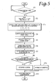
- the voltage measuring section 11 receives the waveforms of counter electromotive forces for three phases generated by the motor 3, and measures and stores the voltage values (K eu , K ev , and K ew ) for U-phase, V-phase, and W-phase to send a signal to the zero crossing detecting section 15.
- the three-phase-to-two-phase converting section 13 reads from the voltage measuring section 11 a U-phase voltage value K eu1 and a V-phase voltage value K ev1 at time t 1 , which is the start point of the angular range signal, and a U-phase voltage value K eu2 and a V-phase voltage value K ev2 at time t 2 , which is the end point of the angular range signal (step ST2).
- the three-phase-to-two-phase converting section 13 then computes V ⁇ 1 and V ⁇ 1 and V ⁇ 2 and V ⁇ 2 through a three-phase-to-two-phase conversion using the formula (1) to send the computed values to the vector variation computing section 23 (step ST3).
- V ⁇ 3 2 ⁇ K eu
- V ⁇ 1 2 ⁇ K eu + 2 ⁇ K ev
- the three-phase-to-two-phase conversion can be performed using only the U-phase voltage value K eu and the V-phase voltage value K ev , among the voltage values for three phases, as is clear from the formula (1), and therefore the W-phase voltage value K ew is not read.
- the vector variation computing section 23 computes the voltage vector variation amount ⁇ V vec based on the received V ⁇ 1 and V ⁇ 1 and V ⁇ 2 and V ⁇ 2 values using the formula (2) (step ST4).
- ⁇ ⁇ V vec V ⁇ ⁇ 2 - V ⁇ ⁇ 1 2 + V ⁇ ⁇ 2 - V ⁇ ⁇ 1 2
- the speed variation detecting section 21 also computes a speed variation amount (number of revolutions) ⁇ N [rpm] in an angular range of 60° ( ⁇ t) based on the frequency ⁇ f using the formula (4) (step ST6).
- the constant computing section 25 computes a counter electromotive force constant K e ⁇ [Vrms/rpm] using the formula (5) (step ST7).
- K e ⁇ ⁇ ⁇ ⁇ V vec 3 / 2 ⁇ ⁇ N ⁇ 1 2
- the constant computing section 25 compares the computed counter electromotive force constant K e ⁇ and a predetermined threshold to determine whether or not the counter electromotive force constant K e ⁇ falls within a predetermined threshold range (step ST8). If the counter electromotive force constant K e ⁇ falls within the threshold range, it is determined that the motor is normal (step ST9). If the counter electromotive force constant K e ⁇ does not fall within the threshold range, it is determined that the motor is abnormal (step ST10).
- the result display section 27 displays an indication for the computed result (step ST11). In the embodiment, the threshold is set within ⁇ 10% of the theoretical value of K e ⁇ .
- the error in the computed counter electromotive force constant can be reduced even when abrupt variations in number of revolutions occur.
- the result display section may be configured to display the computed result or the indication for the computed result if a difference between two voltage vector variation amounts for two divided angular ranges obtained by bisecting the predetermined angular range is equal to or smaller than a predetermined allowable value. If the difference between two voltage vector variation amounts ⁇ V vec is larger than the predetermined allowable value, abrupt variations in number of revolutions are occurring, which tends to cause a significant error in the computed counter electromotive force constant. Thus, the reliability of the inspection results can be improved by causing the result display section 27 to display the computed result or the indication for the computed result only when the difference is equal to or smaller than the allowable value.
- a plurality of counter electromotive force constants K e ⁇ may be computed based on a plurality of angular range signals, rather than a single angular range signal, and a determination may be made based on the average of the plurality of counter electromotive force constants. This further reduces the error.
- the zero crossing detecting section 15 may be configured to additionally detect zero crossing points for V ⁇ and V ⁇ , which allows detection of an angular range of 30° through a combination of zero crossing waveforms for U-phase, V-phase, W-phase, V ⁇ , and V ⁇ .
- the error can be further reduced for an angular range of 30° compared to an angular range of 60°.
- the present invention is directed to three-phase motors, whose W-phase voltage value can be obtained through calculation using measured voltage values for the other two phases, namely U-phase and V-phase. Therefore, it is a matter of course that the voltage measuring section 11 may measure only the voltage values for U-phase and V-phase and obtain the voltage value for W-phase through calculation.
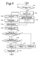
- Fig. 6 is a flowchart showing a second embodiment where the motor condition inspection method according to the present invention is applied to a linear motor that generates counter electromotive forces for three phases.
- steps that are common to those according to the first embodiment are denoted by reference numerals obtained by adding 100 to the reference numerals shown in Fig. 5 .
- a linear motor is to be inspected, in step ST106, a speed variation amount ⁇ V [m/s] for an angular range of 60° ( ⁇ t) in terms of electrical angle is computed based on the frequency ⁇ f using the formula (6).
- ⁇ ⁇ V ⁇ p ⁇ ⁇ ⁇ f
- ⁇ p stands for the pole pitch [m] of the linear motor.
- step ST107 a counter electromotive force constant K e ⁇ [Vrms/m/s] is computed using the formula (7).
- K e ⁇ ⁇ ⁇ ⁇ V vec 3 / 2 ⁇ ⁇ V ⁇ 1 2
- step ST108 it is determined whether or not the counter electromotive force constant K e ⁇ falls within a certain threshold range. If the counter electromotive force constant K e ⁇ falls within the threshold range, it is determined that the gap size is appropriate (step ST109). If the counter electromotive force constant K e ⁇ does not fall within the threshold range, it is determined whether or not the counter electromotive force constant K e ⁇ exceeds the threshold range (step ST110). If the counter electromotive force constant K e ⁇ exceeds the threshold range, it is determined that the gap size is small (step ST111). If the counter electromotive force constant K e ⁇ falls below the threshold range, it is determined that the gap size is large (step ST112). Finally, the result display section 27 displays an indication for the computed result including the counter electromotive force constant (step ST113).
- the characteristics of a motor can be accurately inspected based on the waveforms of counter electromotive forces for three phases.
- the characteristics of the motor can be inspected without removing the motor from an apparatus and without the need for a tachometer or a speed sensor.
Landscapes
- Physics & Mathematics (AREA)
- General Physics & Mathematics (AREA)
- Tests Of Circuit Breakers, Generators, And Electric Motors (AREA)
- Control Of Ac Motors In General (AREA)
Applications Claiming Priority (1)
| Application Number | Priority Date | Filing Date | Title |
|---|---|---|---|
| JP2011015281A JP5656671B2 (ja) | 2011-01-27 | 2011-01-27 | モータの状況検査方法及びモータ特性検査装置 |
Publications (2)
| Publication Number | Publication Date |
|---|---|
| EP2482091A1 true EP2482091A1 (de) | 2012-08-01 |
| EP2482091B1 EP2482091B1 (de) | 2013-08-07 |
Family
ID=45656757
Family Applications (1)
| Application Number | Title | Priority Date | Filing Date |
|---|---|---|---|
| EP12275005.2A Not-in-force EP2482091B1 (de) | 2011-01-27 | 2012-01-27 | Verfahren zur Inspektion des Motorzustands und Vorrichtung zur Inspektion der Motoreigenschaften |
Country Status (5)
| Country | Link |
|---|---|
| US (1) | US8918301B2 (de) |
| EP (1) | EP2482091B1 (de) |
| JP (1) | JP5656671B2 (de) |
| KR (1) | KR20120087088A (de) |
| CN (1) | CN102621490B (de) |
Families Citing this family (7)
| Publication number | Priority date | Publication date | Assignee | Title |
|---|---|---|---|---|
| CN104765002B (zh) * | 2014-01-03 | 2017-09-19 | 广东美的制冷设备有限公司 | 空调器室内风机电机转速影响因素自检的方法和装置 |
| CN104345274A (zh) * | 2014-10-29 | 2015-02-11 | 上海电机学院 | 一种电机转子缺相故障模拟方法及装置 |
| JP6870555B2 (ja) * | 2017-09-29 | 2021-05-12 | ブラザー工業株式会社 | 監視装置 |
| KR102064815B1 (ko) | 2018-05-14 | 2020-01-10 | 한성중공업 주식회사 | 산업용 전동기의 업사이클링 방법 |
| JP2021056072A (ja) * | 2019-09-30 | 2021-04-08 | 日置電機株式会社 | 検査方法、検査システムおよび検査プログラム |
| KR20220148978A (ko) | 2021-04-29 | 2022-11-08 | 주식회사 오더스팟 | 모바일 키오스크형 주문 제공, 간편결제 시스템 및 방법 |
| CN121485521A (zh) * | 2025-11-25 | 2026-02-06 | 陕西凯迈航空航天机电设备有限公司 | 一种双轴大功率密度伺服驱动器和控制方法、系统、设备及存储介质 |
Citations (3)
| Publication number | Priority date | Publication date | Assignee | Title |
|---|---|---|---|---|
| JPS61124256A (ja) * | 1984-11-21 | 1986-06-12 | Showa Electric Wire & Cable Co Ltd | ボイスコイル型リニアモ−タの動的推力測定法 |
| JP2002267727A (ja) * | 2001-03-09 | 2002-09-18 | Meidensha Corp | Pmモータの特性試験装置と方法 |
| JP2009177091A (ja) | 2008-01-28 | 2009-08-06 | Nec Infrontia Corp | 増設プリント基板、積層プリント基板および電子機器 |
Family Cites Families (13)
| Publication number | Priority date | Publication date | Assignee | Title |
|---|---|---|---|---|
| US3006A (en) * | 1843-03-17 | Improvement in cotton-presses | ||
| JP3099681B2 (ja) * | 1995-06-02 | 2000-10-16 | 富士電機株式会社 | 交流電動機の可変速制御装置 |
| US6208497B1 (en) * | 1997-06-26 | 2001-03-27 | Venture Scientifics, Llc | System and method for servo control of nonlinear electromagnetic actuators |
| JP2001171533A (ja) * | 1999-12-20 | 2001-06-26 | Toyoda Mach Works Ltd | 電動パワーステアリング装置 |
| US6686761B2 (en) * | 2000-06-27 | 2004-02-03 | Industrial Technology Research Institute | Method for determining whether a rotor is good in magnetic induction by measuring the EMF of a motor |
| US7340968B2 (en) * | 2002-05-21 | 2008-03-11 | Thermo Fisher Scientific (Asheville) Llc | Back EMF measurement to overcome the effects of motor temperature change |
| TWI227331B (en) * | 2003-12-26 | 2005-02-01 | Ind Tech Res Inst | Measuring method of induced electromotive force constant of motor |
| JP2006220650A (ja) * | 2005-01-13 | 2006-08-24 | Nippon Densan Corp | モータの検査方法 |
| JP2006280158A (ja) * | 2005-03-30 | 2006-10-12 | Toyota Motor Corp | 多相モータの偏心測定方法およびその装置 |
| CN101383575A (zh) * | 2007-09-05 | 2009-03-11 | 晶致半导体股份有限公司 | 步进电机停转状态的判断装置及判断方法 |
| US8836257B2 (en) * | 2008-10-09 | 2014-09-16 | Bsh Home Appliances Corporation | Household appliance including a fan speed controller |
| JP4988796B2 (ja) * | 2009-07-29 | 2012-08-01 | 山洋電気株式会社 | モータの状況検査方法 |
| JP5183594B2 (ja) * | 2009-07-31 | 2013-04-17 | 日立オートモティブシステムズ株式会社 | モータの制御装置及びそれを備えたモータシステム |
-
2011
- 2011-01-27 JP JP2011015281A patent/JP5656671B2/ja not_active Expired - Fee Related
-
2012
- 2012-01-25 US US13/358,060 patent/US8918301B2/en not_active Expired - Fee Related
- 2012-01-26 KR KR1020120007720A patent/KR20120087088A/ko not_active Withdrawn
- 2012-01-27 EP EP12275005.2A patent/EP2482091B1/de not_active Not-in-force
- 2012-01-29 CN CN201210026916.5A patent/CN102621490B/zh not_active Expired - Fee Related
Patent Citations (3)
| Publication number | Priority date | Publication date | Assignee | Title |
|---|---|---|---|---|
| JPS61124256A (ja) * | 1984-11-21 | 1986-06-12 | Showa Electric Wire & Cable Co Ltd | ボイスコイル型リニアモ−タの動的推力測定法 |
| JP2002267727A (ja) * | 2001-03-09 | 2002-09-18 | Meidensha Corp | Pmモータの特性試験装置と方法 |
| JP2009177091A (ja) | 2008-01-28 | 2009-08-06 | Nec Infrontia Corp | 増設プリント基板、積層プリント基板および電子機器 |
Also Published As
| Publication number | Publication date |
|---|---|
| JP5656671B2 (ja) | 2015-01-21 |
| EP2482091B1 (de) | 2013-08-07 |
| US20120197564A1 (en) | 2012-08-02 |
| CN102621490A (zh) | 2012-08-01 |
| US8918301B2 (en) | 2014-12-23 |
| JP2012154844A (ja) | 2012-08-16 |
| KR20120087088A (ko) | 2012-08-06 |
| CN102621490B (zh) | 2016-02-17 |
Similar Documents
| Publication | Publication Date | Title |
|---|---|---|
| EP2482091B1 (de) | Verfahren zur Inspektion des Motorzustands und Vorrichtung zur Inspektion der Motoreigenschaften | |
| US10267860B2 (en) | Fault detection in induction machines | |
| CN103502827B (zh) | 用于监测机电系统的状况方法和设备 | |
| EP2284552B1 (de) | Verfahren zur Prüfung des Zustands eines Linearmotors | |
| KR101432786B1 (ko) | 모터의 고장진단방법 및 그 시스템 | |
| US10658961B2 (en) | Method for identifying the discrete instantaneous angular speed of an electromechanical system | |
| JP6223461B2 (ja) | インピーダンス解析に基づく電気機械システムの診断方法 | |
| Alwodai et al. | A comparison of different techniques for induction motor rotor fault diagnosis | |
| US10408879B2 (en) | Method and apparatus for diagnosing a fault condition in an electric machine | |
| JP2012154844A5 (de) | ||
| EP1427082A2 (de) | Verfahren und system zur Erkennung von interne Motorfehlern einer Induktionsmaschine | |
| KR101169796B1 (ko) | 유도 전동기의 회전자바 고장 진단시스템 | |
| EP3480610A1 (de) | Diagnose eines wicklungssatzes eines stators | |
| EP4109721B1 (de) | Diagnosevorrichtung für einen permanentmagnet-synchronmotor und wechselrichter mit dieser diagnosevorrichtung | |
| CN113647013A (zh) | 电动机设备的异常诊断装置、电动机设备的异常诊断方法和电动机设备的异常诊断系统 | |
| EP2733497A1 (de) | Verfahren zur Schätzung der Frequenz von Oberschwingungen in einem Wechselstrom zu/von einer Wechselstrommaschine | |
| EP2426502A1 (de) | Verfahren zur Erkennung eines Rotorfehlers in einem Asynchronmotor | |
| CN109962648B (zh) | 一种电机零位检测方法和系统 | |
| Garrido et al. | Speed estimation of an induction motor by current signature analysis | |
| Cristaldi et al. | An inverter-fed induction motor diagnostic tool based on time-domain current analysis | |
| Eltabach et al. | Detection of broken rotor bar of induction motors by spectral analysis of the electromagnetic torque using the Luenberger observer | |
| US20250244406A1 (en) | Fault detection in an electrical power system | |
| KR200266147Y1 (ko) | 직류모터의 회전속도측정장치 | |
| Hwang et al. | A study on dynamic simulation and detection of air-gap eccentricity in induction machines |
Legal Events
| Date | Code | Title | Description |
|---|---|---|---|
| PUAI | Public reference made under article 153(3) epc to a published international application that has entered the european phase |
Free format text: ORIGINAL CODE: 0009012 |
|
| AK | Designated contracting states |
Kind code of ref document: A1 Designated state(s): AL AT BE BG CH CY CZ DE DK EE ES FI FR GB GR HR HU IE IS IT LI LT LU LV MC MK MT NL NO PL PT RO RS SE SI SK SM TR |
|
| AX | Request for extension of the european patent |
Extension state: BA ME |
|
| 17P | Request for examination filed |
Effective date: 20130111 |
|
| GRAP | Despatch of communication of intention to grant a patent |
Free format text: ORIGINAL CODE: EPIDOSNIGR1 |
|
| RIC1 | Information provided on ipc code assigned before grant |
Ipc: G01R 31/34 20060101AFI20130205BHEP |
|
| GRAS | Grant fee paid |
Free format text: ORIGINAL CODE: EPIDOSNIGR3 |
|
| GRAA | (expected) grant |
Free format text: ORIGINAL CODE: 0009210 |
|
| AK | Designated contracting states |
Kind code of ref document: B1 Designated state(s): AL AT BE BG CH CY CZ DE DK EE ES FI FR GB GR HR HU IE IS IT LI LT LU LV MC MK MT NL NO PL PT RO RS SE SI SK SM TR |
|
| REG | Reference to a national code |
Ref country code: GB Ref legal event code: FG4D |
|
| REG | Reference to a national code |
Ref country code: AT Ref legal event code: REF Ref document number: 625984 Country of ref document: AT Kind code of ref document: T Effective date: 20130815 Ref country code: CH Ref legal event code: EP |
|
| REG | Reference to a national code |
Ref country code: IE Ref legal event code: FG4D |
|
| REG | Reference to a national code |
Ref country code: DE Ref legal event code: R096 Ref document number: 602012000197 Country of ref document: DE Effective date: 20131002 |
|
| REG | Reference to a national code |
Ref country code: AT Ref legal event code: MK05 Ref document number: 625984 Country of ref document: AT Kind code of ref document: T Effective date: 20130807 |
|
| REG | Reference to a national code |
Ref country code: NL Ref legal event code: VDEP Effective date: 20130807 |
|
| REG | Reference to a national code |
Ref country code: LT Ref legal event code: MG4D |
|
| PG25 | Lapsed in a contracting state [announced via postgrant information from national office to epo] |
Ref country code: SE Free format text: LAPSE BECAUSE OF FAILURE TO SUBMIT A TRANSLATION OF THE DESCRIPTION OR TO PAY THE FEE WITHIN THE PRESCRIBED TIME-LIMIT Effective date: 20130807 Ref country code: NO Free format text: LAPSE BECAUSE OF FAILURE TO SUBMIT A TRANSLATION OF THE DESCRIPTION OR TO PAY THE FEE WITHIN THE PRESCRIBED TIME-LIMIT Effective date: 20131107 Ref country code: HR Free format text: LAPSE BECAUSE OF FAILURE TO SUBMIT A TRANSLATION OF THE DESCRIPTION OR TO PAY THE FEE WITHIN THE PRESCRIBED TIME-LIMIT Effective date: 20130807 Ref country code: LT Free format text: LAPSE BECAUSE OF FAILURE TO SUBMIT A TRANSLATION OF THE DESCRIPTION OR TO PAY THE FEE WITHIN THE PRESCRIBED TIME-LIMIT Effective date: 20130807 Ref country code: AT Free format text: LAPSE BECAUSE OF FAILURE TO SUBMIT A TRANSLATION OF THE DESCRIPTION OR TO PAY THE FEE WITHIN THE PRESCRIBED TIME-LIMIT Effective date: 20130807 Ref country code: IS Free format text: LAPSE BECAUSE OF FAILURE TO SUBMIT A TRANSLATION OF THE DESCRIPTION OR TO PAY THE FEE WITHIN THE PRESCRIBED TIME-LIMIT Effective date: 20131207 Ref country code: CY Free format text: LAPSE BECAUSE OF FAILURE TO SUBMIT A TRANSLATION OF THE DESCRIPTION OR TO PAY THE FEE WITHIN THE PRESCRIBED TIME-LIMIT Effective date: 20130904 Ref country code: PT Free format text: LAPSE BECAUSE OF FAILURE TO SUBMIT A TRANSLATION OF THE DESCRIPTION OR TO PAY THE FEE WITHIN THE PRESCRIBED TIME-LIMIT Effective date: 20131209 |
|
| PG25 | Lapsed in a contracting state [announced via postgrant information from national office to epo] |
Ref country code: BE Free format text: LAPSE BECAUSE OF FAILURE TO SUBMIT A TRANSLATION OF THE DESCRIPTION OR TO PAY THE FEE WITHIN THE PRESCRIBED TIME-LIMIT Effective date: 20130807 Ref country code: PL Free format text: LAPSE BECAUSE OF FAILURE TO SUBMIT A TRANSLATION OF THE DESCRIPTION OR TO PAY THE FEE WITHIN THE PRESCRIBED TIME-LIMIT Effective date: 20130807 Ref country code: GR Free format text: LAPSE BECAUSE OF FAILURE TO SUBMIT A TRANSLATION OF THE DESCRIPTION OR TO PAY THE FEE WITHIN THE PRESCRIBED TIME-LIMIT Effective date: 20131108 Ref country code: FI Free format text: LAPSE BECAUSE OF FAILURE TO SUBMIT A TRANSLATION OF THE DESCRIPTION OR TO PAY THE FEE WITHIN THE PRESCRIBED TIME-LIMIT Effective date: 20130807 Ref country code: LV Free format text: LAPSE BECAUSE OF FAILURE TO SUBMIT A TRANSLATION OF THE DESCRIPTION OR TO PAY THE FEE WITHIN THE PRESCRIBED TIME-LIMIT Effective date: 20130807 Ref country code: NL Free format text: LAPSE BECAUSE OF FAILURE TO SUBMIT A TRANSLATION OF THE DESCRIPTION OR TO PAY THE FEE WITHIN THE PRESCRIBED TIME-LIMIT Effective date: 20130807 Ref country code: SI Free format text: LAPSE BECAUSE OF FAILURE TO SUBMIT A TRANSLATION OF THE DESCRIPTION OR TO PAY THE FEE WITHIN THE PRESCRIBED TIME-LIMIT Effective date: 20130807 |
|
| PG25 | Lapsed in a contracting state [announced via postgrant information from national office to epo] |
Ref country code: CY Free format text: LAPSE BECAUSE OF FAILURE TO SUBMIT A TRANSLATION OF THE DESCRIPTION OR TO PAY THE FEE WITHIN THE PRESCRIBED TIME-LIMIT Effective date: 20130807 |
|
| PG25 | Lapsed in a contracting state [announced via postgrant information from national office to epo] |
Ref country code: SK Free format text: LAPSE BECAUSE OF FAILURE TO SUBMIT A TRANSLATION OF THE DESCRIPTION OR TO PAY THE FEE WITHIN THE PRESCRIBED TIME-LIMIT Effective date: 20130807 Ref country code: DK Free format text: LAPSE BECAUSE OF FAILURE TO SUBMIT A TRANSLATION OF THE DESCRIPTION OR TO PAY THE FEE WITHIN THE PRESCRIBED TIME-LIMIT Effective date: 20130807 Ref country code: EE Free format text: LAPSE BECAUSE OF FAILURE TO SUBMIT A TRANSLATION OF THE DESCRIPTION OR TO PAY THE FEE WITHIN THE PRESCRIBED TIME-LIMIT Effective date: 20130807 Ref country code: RO Free format text: LAPSE BECAUSE OF FAILURE TO SUBMIT A TRANSLATION OF THE DESCRIPTION OR TO PAY THE FEE WITHIN THE PRESCRIBED TIME-LIMIT Effective date: 20130807 Ref country code: CZ Free format text: LAPSE BECAUSE OF FAILURE TO SUBMIT A TRANSLATION OF THE DESCRIPTION OR TO PAY THE FEE WITHIN THE PRESCRIBED TIME-LIMIT Effective date: 20130807 |
|
| PG25 | Lapsed in a contracting state [announced via postgrant information from national office to epo] |
Ref country code: ES Free format text: LAPSE BECAUSE OF FAILURE TO SUBMIT A TRANSLATION OF THE DESCRIPTION OR TO PAY THE FEE WITHIN THE PRESCRIBED TIME-LIMIT Effective date: 20130807 Ref country code: IT Free format text: LAPSE BECAUSE OF FAILURE TO SUBMIT A TRANSLATION OF THE DESCRIPTION OR TO PAY THE FEE WITHIN THE PRESCRIBED TIME-LIMIT Effective date: 20130807 |
|
| PLBE | No opposition filed within time limit |
Free format text: ORIGINAL CODE: 0009261 |
|
| STAA | Information on the status of an ep patent application or granted ep patent |
Free format text: STATUS: NO OPPOSITION FILED WITHIN TIME LIMIT |
|
| 26N | No opposition filed |
Effective date: 20140508 |
|
| REG | Reference to a national code |
Ref country code: DE Ref legal event code: R097 Ref document number: 602012000197 Country of ref document: DE Effective date: 20140508 |
|
| PG25 | Lapsed in a contracting state [announced via postgrant information from national office to epo] |
Ref country code: LU Free format text: LAPSE BECAUSE OF FAILURE TO SUBMIT A TRANSLATION OF THE DESCRIPTION OR TO PAY THE FEE WITHIN THE PRESCRIBED TIME-LIMIT Effective date: 20140127 |
|
| REG | Reference to a national code |
Ref country code: FR Ref legal event code: ST Effective date: 20140930 |
|
| REG | Reference to a national code |
Ref country code: IE Ref legal event code: MM4A |
|
| PG25 | Lapsed in a contracting state [announced via postgrant information from national office to epo] |
Ref country code: FR Free format text: LAPSE BECAUSE OF NON-PAYMENT OF DUE FEES Effective date: 20140131 |
|
| PG25 | Lapsed in a contracting state [announced via postgrant information from national office to epo] |
Ref country code: IE Free format text: LAPSE BECAUSE OF NON-PAYMENT OF DUE FEES Effective date: 20140127 |
|
| PG25 | Lapsed in a contracting state [announced via postgrant information from national office to epo] |
Ref country code: MC Free format text: LAPSE BECAUSE OF FAILURE TO SUBMIT A TRANSLATION OF THE DESCRIPTION OR TO PAY THE FEE WITHIN THE PRESCRIBED TIME-LIMIT Effective date: 20130807 |
|
| REG | Reference to a national code |
Ref country code: CH Ref legal event code: PL |
|
| PG25 | Lapsed in a contracting state [announced via postgrant information from national office to epo] |
Ref country code: CH Free format text: LAPSE BECAUSE OF NON-PAYMENT OF DUE FEES Effective date: 20150131 Ref country code: LI Free format text: LAPSE BECAUSE OF NON-PAYMENT OF DUE FEES Effective date: 20150131 |
|
| PG25 | Lapsed in a contracting state [announced via postgrant information from national office to epo] |
Ref country code: MT Free format text: LAPSE BECAUSE OF FAILURE TO SUBMIT A TRANSLATION OF THE DESCRIPTION OR TO PAY THE FEE WITHIN THE PRESCRIBED TIME-LIMIT Effective date: 20130807 |
|
| PG25 | Lapsed in a contracting state [announced via postgrant information from national office to epo] |
Ref country code: SM Free format text: LAPSE BECAUSE OF FAILURE TO SUBMIT A TRANSLATION OF THE DESCRIPTION OR TO PAY THE FEE WITHIN THE PRESCRIBED TIME-LIMIT Effective date: 20130807 |
|
| PGFP | Annual fee paid to national office [announced via postgrant information from national office to epo] |
Ref country code: DE Payment date: 20160120 Year of fee payment: 5 |
|
| PG25 | Lapsed in a contracting state [announced via postgrant information from national office to epo] |
Ref country code: RS Free format text: LAPSE BECAUSE OF NON-PAYMENT OF DUE FEES Effective date: 20130807 Ref country code: BG Free format text: LAPSE BECAUSE OF FAILURE TO SUBMIT A TRANSLATION OF THE DESCRIPTION OR TO PAY THE FEE WITHIN THE PRESCRIBED TIME-LIMIT Effective date: 20130807 |
|
| PG25 | Lapsed in a contracting state [announced via postgrant information from national office to epo] |
Ref country code: HU Free format text: LAPSE BECAUSE OF FAILURE TO SUBMIT A TRANSLATION OF THE DESCRIPTION OR TO PAY THE FEE WITHIN THE PRESCRIBED TIME-LIMIT; INVALID AB INITIO Effective date: 20120127 Ref country code: TR Free format text: LAPSE BECAUSE OF FAILURE TO SUBMIT A TRANSLATION OF THE DESCRIPTION OR TO PAY THE FEE WITHIN THE PRESCRIBED TIME-LIMIT Effective date: 20130807 |
|
| GBPC | Gb: european patent ceased through non-payment of renewal fee |
Effective date: 20160127 |
|
| PG25 | Lapsed in a contracting state [announced via postgrant information from national office to epo] |
Ref country code: GB Free format text: LAPSE BECAUSE OF NON-PAYMENT OF DUE FEES Effective date: 20160127 |
|
| REG | Reference to a national code |
Ref country code: DE Ref legal event code: R119 Ref document number: 602012000197 Country of ref document: DE |
|
| PG25 | Lapsed in a contracting state [announced via postgrant information from national office to epo] |
Ref country code: DE Free format text: LAPSE BECAUSE OF NON-PAYMENT OF DUE FEES Effective date: 20170801 |
|
| PG25 | Lapsed in a contracting state [announced via postgrant information from national office to epo] |
Ref country code: MK Free format text: LAPSE BECAUSE OF FAILURE TO SUBMIT A TRANSLATION OF THE DESCRIPTION OR TO PAY THE FEE WITHIN THE PRESCRIBED TIME-LIMIT Effective date: 20130807 |
|
| PG25 | Lapsed in a contracting state [announced via postgrant information from national office to epo] |
Ref country code: AL Free format text: LAPSE BECAUSE OF FAILURE TO SUBMIT A TRANSLATION OF THE DESCRIPTION OR TO PAY THE FEE WITHIN THE PRESCRIBED TIME-LIMIT Effective date: 20130807 |