EP2480484B2 - Portalhubwagen zum einsatz in containerterminals und für allgemeine transportzwecke - Google Patents
Portalhubwagen zum einsatz in containerterminals und für allgemeine transportzwecke Download PDFInfo
- Publication number
- EP2480484B2 EP2480484B2 EP10763602.9A EP10763602A EP2480484B2 EP 2480484 B2 EP2480484 B2 EP 2480484B2 EP 10763602 A EP10763602 A EP 10763602A EP 2480484 B2 EP2480484 B2 EP 2480484B2
- Authority
- EP
- European Patent Office
- Prior art keywords
- drive unit
- lift truck
- generator
- straddle carrier
- framework
- Prior art date
- Legal status (The legal status is an assumption and is not a legal conclusion. Google has not performed a legal analysis and makes no representation as to the accuracy of the status listed.)
- Active
Links
Images

Classifications
-
- B—PERFORMING OPERATIONS; TRANSPORTING
- B66—HOISTING; LIFTING; HAULING
- B66C—CRANES; LOAD-ENGAGING ELEMENTS OR DEVICES FOR CRANES, CAPSTANS, WINCHES, OR TACKLES
- B66C13/00—Other constructional features or details
- B66C13/18—Control systems or devices
- B66C13/22—Control systems or devices for electric drives
-
- B—PERFORMING OPERATIONS; TRANSPORTING
- B66—HOISTING; LIFTING; HAULING
- B66C—CRANES; LOAD-ENGAGING ELEMENTS OR DEVICES FOR CRANES, CAPSTANS, WINCHES, OR TACKLES
- B66C19/00—Cranes comprising trolleys or crabs running on fixed or movable bridges or gantries
- B66C19/007—Cranes comprising trolleys or crabs running on fixed or movable bridges or gantries for containers
Definitions
- the invention relates to a straddle carrier for use in container terminals and for general transport purposes, with a frame, a load handling device, preferably a spreader or top spreader, which hangs between the frame and can be locked to a load, preferably a container, lifting winches, by means of which the load handling device is vertically movable, running gears which are arranged on the lower area of the frame and each have a plurality of wheels arranged in a row, and a drive unit, by means of which the drive energy required for operating the straddle carrier can be generated and which has a diesel engine and a generator having.
- a straddle carrier is from DE 20 2004 018 066 U1 known.
- the drive unit is usually arranged on an upper frame of the frame.
- the drive unit is formed by a diesel engine which is coupled to a synchronous generator, less often to an asynchronous generator, via a coupling device.
- synchronous or asynchronous generators have, on the one hand, a comparatively large overall axial length and, moreover, are considerable in weight. This has detrimental effects on the center of gravity of the straddle carrier, which, for example, can influence the stability of the same.
- the invention is based on the object of developing the generic straddle carrier in such a way that the drive energy required for its operation can be made available more cheaply.
- a straddle carrier which, in addition to the features of the preamble of the patent claim, also has those of the characterizing part of the patent claim.
- a permanently excited generator (PEM) with comparable performance indicators has a considerably reduced weight, the weight reduction being in the range of 50% or more. Accordingly, the overall axial length of a permanently excited generator (PEM) is significantly less than that of a synchronous or asynchronous motor previously used for such straddle carriers, whereby the reduction factor can be in the range of 50% or more.
- the weight reduction results in a shift in the center of gravity of the straddle carrier in a downward direction, which increases the operational safety of the straddle carrier.
- the drive unit to which the diesel engine and the permanently excited generator (PEM) belong, can be realized with a considerably reduced overall length and with a considerably reduced weight, so that the drive unit in preassembled form with a considerably reduced transport effort between its production site and the place of their assembly can be transported with the rest of the straddle carrier.
- special transport measures can be dispensed with.
- a straddle carrier 1 which is explained below, has a frame 2, which is arranged in the manner of a portal 2 at the lower end of the frame 2 undercarriages 3, of which in Figure 1 only one thing is visible, connects with each other.
- the straddle carrier 1 includes a load-handling device (spreader, top spreader) 4, which is arranged between the vertical supports 5 of the frame 2 assigned to the two chassis 3.
- the load-bearing means 4 can be connected or locked to a container 7 by suitable connecting means 6.
- the load handling device 4 is also by means of a device shown in FIG Figure 1
- the embodiment shown of the straddle carrier 1 on the lifting device 4 arranged on the lifting winch 8 between the vertical supports 5 of the frame 2 is vertically movable.
- a driver's cab 10 is provided on an upper frame 9 of the frame 2, from which an operator of the straddle carrier 1 can drive or control the latter and its load handling device 4.
- the individual units of the straddle carrier 1, such as the hoisting winch 8 and the wheel drives 9, are supplied with drive energy by means of a drive unit 13.
- the drive unit 13 is arranged on the upper frame 9 of the frame 2.
- the drive unit 13 has a diesel engine 14 which directly drives a permanently excited generator (PEM) 15.
- PEM permanently excited generator
- the weight of the drive unit 13 can be reduced considerably, since the permanently excited generator (PEM) 15 compared to the Synchronous or asynchronous generators conventionally used for drive units of straddle carriers 1 have a considerably reduced weight.
- permanently excited generators (PEM) 15 weigh approximately half the weight of synchronous or asynchronous generators having corresponding performance characteristics.
- the dimensions of the drive unit 13 of the straddle carrier 1 can be significantly reduced, since the permanently excited generator (PEM) 15 can be coupled directly to the output side of the diesel engine 14 and since the axial dimension of the permanently excited generator (PEM) 15 is considerably smaller than the corresponding axial dimension of a synchronous or asynchronous motor of comparable power usually used for drive units of straddle carriers 1.
- PEM permanently excited generator
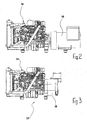
- a comparison of the Figures 2 and 3 shows how much the overall length of the drive unit 13 can be reduced by using the permanently excited generator (PEM) 15.
- PEM permanently excited generator
- the drive units shown have the same power, coupled permanently excited generator (PEM) 15 has, as can be seen from the comparison of the two Figures 2 and 3 results in an overall axial length that is only 40 to 50, in the exemplary embodiment shown approx. 46.5%, of the overall axial length of the in Figure 2 has synchronous generator 16 shown. Accordingly, the overall axial length of the drive unit 13 can be compared to that in FIG Figure 2 shown prior art in the case of the straddle carrier 1 according to the invention significantly reduce.
Landscapes
- Engineering & Computer Science (AREA)
- Mechanical Engineering (AREA)
- Automation & Control Theory (AREA)
- Carriers, Traveling Bodies, And Overhead Traveling Cranes (AREA)
- Handcart (AREA)
- Ship Loading And Unloading (AREA)
- Load-Engaging Elements For Cranes (AREA)
- Hybrid Electric Vehicles (AREA)
- Connection Of Motors, Electrical Generators, Mechanical Devices, And The Like (AREA)
Description
- Die Erfindung bezieht sich auf einen Portalhubwagen zum Einsatz in Containerterminals und für allgemeine Transportzwecke, mit einem Rahmengestell, einem Lastaufnahmemittel, vorzugsweise einem Spreader oder Toppspreader, das zwischen dem Rahmengestell hängt und mit einer Last, vorzugsweise einem Container, verriegelbar ist, Hubwinden, mittels denen das Lastaufnahmemittel vertikal bewegbar ist, Fahrwerken, die am unteren Bereich des Rahmengestells angeordnet sind und jeweils eine Vielzahl in einer Reihe angeordneter Räder aufweisen, und einer Antriebseinheit, mittels der die für den Betrieb des Portalhubwagens erforderliche Antriebsenergie erzeugbar ist und die einen Dieselmotor und einen Generator aufweist. Ein derartiger Portalhubwagen ist aus der
DE 20 2004 018 066 U1 bekannt. - Bei bekannten derartigen Portalhubwagen, auch Straddle Carrier genannt, ist die Antriebseinheit üblicherweise an einem Oberrahmen des Rahmengestells angeordnet. Die Antriebseinheit wird durch einen Dieselmotor, der über eine Kupplungseinrichtung an einen Synchron-, seltener an einen Asynchrongenerator gekoppelt ist, gebildet. Derartige Synchron- oder Asynchrongeneratoren haben zum einen eine vergleichsweise große axiale Baulänge und darüber hinaus ein erhebliches Gewicht. Dies hat nachteilige Auswirkungen auf die Schwerpunktlage des Portalhubwagens, die beispielsweise die Kippsicherheit desselben beeinflussen kann.
- Ausgehend von dem vorstehend geschilderten Stand der Technik liegt der Erfindung die Aufgabe zugrunde, den gattungsgemäßen Portalhubwagen derart weiterzubilden, dass die für seinen Betrieb erforderliche Antriebsenergie günstiger zur Verfügung gestellt werden kann.
- Diese Aufgabe wird erfindungsgemäß durch einen Portalhubwagen, der neben den Merkmalen des Oberbegriffs des Patentanspruchs auch die des kennzeichnenden Teils des Patentanspruchs aufweist, gelöst. Im Vergleich zu den bisher aus dem Stand der Technik bekannten herkömmlichen Synchron- und Asynchronmotoren hat ein über vergleichbare Leistungskennziffern verfügender permanent erregter Generator (PEM) ein erheblich reduziertes Gewicht, wobei die Gewichtsreduzierung im Bereich von 50 % oder darüber liegen kann. Entsprechend ist die axiale Baulänge eines permanent erregten Generators (PEM) wesentlich geringer als die eines bisher für derartige Portalhubwagen eingesetzten Synchron- oder Asynchronmotors, wobei auch hier der Reduzierungsfaktor im Bereich von 50 % oder darüber liegen kann.
- Durch die Gewichtsreduzierung ergibt sich eine Verlagerung der Schwerpunktlage des Portalhubwagens in abwärtiger Richtung, was die Betriebssicherheit des Portalhubwagens erhöht. Darüber hinaus lässt sich die Antriebseinheit, zu der der Dieselmotor und der permanent erregte Generator (PEM) gehören, mit einer erheblich reduzierten Baulänge und mit einem erheblich reduzierten Gewicht realisieren, so dass die Antriebseinheit in vormontierter Form mit einem erheblich reduzierten Transportaufwand zwischen ihrer Herstellungsstätte und dem Ort ihres Zusammenbaus mit dem übrigen Portalhubwagen transportiert werden kann. Zum Beispiel kann auf Sondertransportmaßnahmen verzichtet werden.
- Im Folgenden wird die Erfindung anhand einer Ausführungsform unter Bezugnahme auf die Zeichnung näher erläutert.
- Es zeigen:
- Figur 1
- eine Prinzipdarstellung eines erfindungsgemäßen Portalhubwagens (Straddle Carrier);
- Figur 2
- eine Prinzipdarstellung einer aus dem Stand der Technik bekannten Antriebseinheit eines Portalhubwagens, und
- Figur 3
- eine Prinzipdarstellung einer Antriebseinheit eines erfindungsgemäßen Portalhubwagens.
- Eine anhand der
Figuren 1 und3 im Folgenden erläuterte Ausführungsform eines erfindungsgemäßen Portalhubwagens (Straddle Carrier) 1 hat ein Rahmengestell 2, welches nach Art eines Portals 2 am unteren Ende des Rahmengestells 2 angeordnete Fahrwerke 3, von denen inFigur 1 nur eines sichtbar ist, miteinander verbindet. - Zu dem Portalhubwagen 1 gehört ein Lastaufnahmemittel (Spreader, Toppspreader) 4, das zwischen den beiden Fahrwerken 3 zugeordneten vertikalen Stützen 5 des Rahmengestells 2 angeordnet ist. Das Lastaufnahmemittel 4 ist durch geeignete Verbindungsmittel 6 mit einem Container 7 verbind- bzw. verriegelbar. Das Lastaufnahmemittel 4 ist des Weiteren mittels einer in der in
Figur 1 gezeigten Ausführungsform des Portalhubwagens 1 am Lastaufnahmemittel 4 angeordneten Hubwinde 8 zwischen den vertikalen Stützen 5 des Rahmengestells 2 vertikal bewegbar. - An einem Oberrahmen 9 des Rahmengestells 2 ist eine Fahrerkabine 10 vorgesehen, aus der heraus eine Bedienungsperson des Portalhubwagens 1 diesen und sein Lastaufnahmemittel 4 fahren bzw. steuern kann.
- Die beiden Fahrwerke 3 des Portalhubwagens 1, von denen in
Figur 1 , wie bereits erwähnt, nur eines sichtbar ist, haben in der dargestellten Ausführungsform des Portalhubwagens 1 vier Räder 11, denen jeweils ein am Fahrwerk 3 gehalterter Radantrieb 12 zugeordnet ist. - Die einzelnen Aggregate des Portalhubwagens 1, wie die Hubwinde 8 und die Radantriebe 9, werden mittels einer Antriebseinheit 13 mit Antriebsenergie versorgt. Die Antriebseinheit 13 ist in der dargestellten Ausführungsform des Portalhubwagens am Oberrahmen 9 des Rahmengestells 2 angeordnet.
- Die Antriebseinheit 13 hat einen Dieselmotor 14, der unmittelbar einen permanent erregten Generator (PEM) 15 antreibt. Durch den Einsatz des permanent erregten Generators (PEM) 15 kann das Gewicht der Antriebseinheit 13 erheblich reduziert werden, da der permanent erregte Generator (PEM) 15 im Vergleich zu den herkömmlicherweise für Antriebseinheiten von Portalhubwagen 1 eingesetzten Synchron- oder Asynchrongeneratoren ein erheblich reduziertes Gewicht aufweist. Üblicherweise wiegen permanent erregte Generatoren (PEM) 15 ca. die Hälfte wie entsprechende Leistungskennwerte aufweisende Synchron- oder Asynchrongeneratoren.
- Darüber hinaus lassen sich die Abmessungen der Antriebseinheit 13 des Portalhubwagens 1 erheblich verkleinern, da der permanent erregte Generator (PEM) 15 unmittelbar an der Ausgangsseite des Dieselmotors 14 gekoppelt werden kann und da die Axialabmessung des permanent erregten Generators (PEM) 15 erheblich geringer ist als die entsprechende Axialabmessung eines üblicherweise für Antriebseinheiten von Portalhubwagen 1 eingesetzten Synchron- oder Asynchronmotors vergleichbarer Leistung.
- Ein Vergleich der
Figuren 2 und 3 zeigt, um wieviel sich die Baulänge der Antriebseinheit 13 durch den Einsatz des permanent erregten Generators (PEM) 15 reduzieren lässt. Ein an den Dieselmotor 14, der im Falle beider in denFiguren 2 und 3 gezeigter Antriebseinheiten die gleiche Leistung aufweist, gekoppelter permanent erregter Generator (PEM) 15 hat, wie sich aus dem Vergleich der beidenFiguren 2 und 3 ergibt, eine axiale Baulänge, die lediglich 40 bis 50, im gezeigten Ausführungsbeispiel ca. 46,5 %, der axialen Baulänge des inFigur 2 gezeigten Synchrongenerators 16 aufweist. Entsprechend lässt sich die gesamte axiale Baulänge der Antriebseinheit 13 im Vergleich zu dem inFigur 2 gezeigten Stand der Technik im Falle des erfindungsgemäßen Portalhubwagens 1 erheblich reduzieren.
Claims (1)
- Portalhubwagen zum Einsatz in Containerterminals und für allgemeine Transportzwecke, mit einem Rahmengestell (2), einem Lastaufnahmemittel (4), vorzugsweise einem Spreader oder Toppspreader, das zwischen dem Rahmengestell (2) hängt und mit einer Last, vorzugsweise einem Container (7), verriegelbar ist, Hubwinden (8), mittels denen das Lastaufnahmemittel (4) vertikal bewegbar ist, Fahrwerken (3), die am unteren Bereich des Rahmengestells (2) angeordnet sind und jeweils eine Vielzahl in einer Reihe angeordneter Räder (11) aufweisen, und einer Antriebseinheit (13), mittels der die für den Betrieb des Portalhubwagens (1) erforderliche Antriebsenergie erzeugbar ist und die einen Dieselmotor (14) und einen Generator (15) aufweist, dadurch gekennzeichnet, dass der Generator (15) der Antriebseinheit (13) als permanent erregter Generator (PEM) (15) ausgebildet ist, und dass am Lastaufnahmemittel (4) eine Hubwinde (8), mittels der das Lastaufnahmemittel (4) zwischen vertikalen Stützen (5) des Rahmengestells vertikal bewegbar ist, angeordnet ist.
Priority Applications (1)
| Application Number | Priority Date | Filing Date | Title |
|---|---|---|---|
| PL10763602T PL2480484T5 (pl) | 2009-09-23 | 2010-09-22 | Kontenerowy wóz bramowy do stosowania w terminalach kontenerowych i dla ogólnych zadań transportowych |
Applications Claiming Priority (2)
| Application Number | Priority Date | Filing Date | Title |
|---|---|---|---|
| DE102009042677A DE102009042677A1 (de) | 2009-09-23 | 2009-09-23 | Portalhubwagen zum Einsatz in Containerterminals und für allgemeine Transportzwecke |
| PCT/EP2010/005782 WO2011035890A1 (de) | 2009-09-23 | 2010-09-22 | Portalhubwagen zum einsatz in containerterminals und für allgemeine transportzwecke |
Publications (3)
| Publication Number | Publication Date |
|---|---|
| EP2480484A1 EP2480484A1 (de) | 2012-08-01 |
| EP2480484B1 EP2480484B1 (de) | 2015-03-25 |
| EP2480484B2 true EP2480484B2 (de) | 2020-12-30 |
Family
ID=43386048
Family Applications (1)
| Application Number | Title | Priority Date | Filing Date |
|---|---|---|---|
| EP10763602.9A Active EP2480484B2 (de) | 2009-09-23 | 2010-09-22 | Portalhubwagen zum einsatz in containerterminals und für allgemeine transportzwecke |
Country Status (6)
| Country | Link |
|---|---|
| EP (1) | EP2480484B2 (de) |
| CN (1) | CN102666355B (de) |
| DE (1) | DE102009042677A1 (de) |
| ES (1) | ES2538077T5 (de) |
| PL (1) | PL2480484T5 (de) |
| WO (1) | WO2011035890A1 (de) |
Families Citing this family (2)
| Publication number | Priority date | Publication date | Assignee | Title |
|---|---|---|---|---|
| DE102015008038A1 (de) * | 2015-06-23 | 2016-12-29 | Liebherr-Components Biberach Gmbh | Kran sowie Verfahren zu dessen Steuerung |
| CN106865421A (zh) * | 2017-04-17 | 2017-06-20 | 中国水利水电第十二工程局有限公司 | 运输吊装装置 |
Citations (3)
| Publication number | Priority date | Publication date | Assignee | Title |
|---|---|---|---|---|
| DE19711701A1 (de) † | 1997-03-20 | 1998-04-30 | Still Gmbh | Drehstromantrieb für Flurförderzeuge mit Verbrennungsmotor |
| DE202004018066U1 (de) † | 2004-11-20 | 2005-02-03 | Noell Mobile Systems & Cranes Gmbh | Portalhubstapler für Container |
| DE102006010536A1 (de) † | 2006-03-07 | 2007-09-20 | Siemens Ag | Dieselelektrisches Antriebssystem mit einem permanent erregten Synchrongenerator |
Family Cites Families (5)
| Publication number | Priority date | Publication date | Assignee | Title |
|---|---|---|---|---|
| US4715762A (en) * | 1983-02-24 | 1987-12-29 | Mi-Jack Products, Inc. | Grappler system for lifting apparatus |
| CN1945963A (zh) * | 2006-09-01 | 2007-04-11 | 罗中柱 | 直流母线供电的起重机动力系统 |
| DE202006020028U1 (de) * | 2006-11-25 | 2007-08-09 | Noell Mobile Systems Gmbh | Portalhubstapler mit einem emissions- und wartungsarmen Turbinenantrieb |
| CN101012046A (zh) * | 2007-02-06 | 2007-08-08 | 上海港机重工有限公司 | 轮胎式龙门起重机 |
| DE202008004985U1 (de) * | 2008-04-10 | 2009-08-13 | Liebherr-Werk Biberach Gmbh | Winde |
-
2009
- 2009-09-23 DE DE102009042677A patent/DE102009042677A1/de not_active Withdrawn
-
2010
- 2010-09-22 EP EP10763602.9A patent/EP2480484B2/de active Active
- 2010-09-22 CN CN201080042942.6A patent/CN102666355B/zh active Active
- 2010-09-22 PL PL10763602T patent/PL2480484T5/pl unknown
- 2010-09-22 ES ES10763602T patent/ES2538077T5/es active Active
- 2010-09-22 WO PCT/EP2010/005782 patent/WO2011035890A1/de not_active Ceased
Patent Citations (3)
| Publication number | Priority date | Publication date | Assignee | Title |
|---|---|---|---|---|
| DE19711701A1 (de) † | 1997-03-20 | 1998-04-30 | Still Gmbh | Drehstromantrieb für Flurförderzeuge mit Verbrennungsmotor |
| DE202004018066U1 (de) † | 2004-11-20 | 2005-02-03 | Noell Mobile Systems & Cranes Gmbh | Portalhubstapler für Container |
| DE102006010536A1 (de) † | 2006-03-07 | 2007-09-20 | Siemens Ag | Dieselelektrisches Antriebssystem mit einem permanent erregten Synchrongenerator |
Also Published As
| Publication number | Publication date |
|---|---|
| DE102009042677A1 (de) | 2011-03-24 |
| CN102666355A (zh) | 2012-09-12 |
| WO2011035890A1 (de) | 2011-03-31 |
| ES2538077T5 (es) | 2021-09-29 |
| PL2480484T5 (pl) | 2021-05-17 |
| PL2480484T3 (pl) | 2015-08-31 |
| CN102666355B (zh) | 2015-04-01 |
| EP2480484A1 (de) | 2012-08-01 |
| ES2538077T3 (es) | 2015-06-17 |
| EP2480484B1 (de) | 2015-03-25 |
Similar Documents
| Publication | Publication Date | Title |
|---|---|---|
| EP2242672B1 (de) | Modulares bremsgerüst | |
| WO2017072241A1 (de) | Schwerlaststapler | |
| DE102009009116A1 (de) | Triebzug und Verfahren zu dessen Herstellung | |
| WO2006027030A1 (de) | Instandhaltungsfahrzeug | |
| EP1948551B1 (de) | Mobiler grosskran | |
| EP2490977B1 (de) | Portalhubwagen mit einzelseilwinden | |
| WO2007077056A1 (de) | Fördersystem | |
| EP3212560A1 (de) | Portalhubgerät für iso-container | |
| DE102008047737A1 (de) | Mobiler Kran mit mindestens einem Kranausleger | |
| DE102007043280A1 (de) | Mitgehhubwagen | |
| EP2480484B1 (de) | Portalhubwagen zum einsatz in containerterminals und für allgemeine transportzwecke | |
| DE102015008684A1 (de) | Tragrahmen für eine Traktionsbatterie sowie Halteanordnung einer solchen Traktionsbatterie an einen Aufbau eines Fahrzeugs | |
| EP2480486B1 (de) | Portalhubwagen zum einsatz in containerterminals und für allgemeine transportaufgaben | |
| EP2483573B1 (de) | Portalhubwagen zum einsatz in containerterminals und für andere transportaufgaben | |
| DE202004018066U1 (de) | Portalhubstapler für Container | |
| DE10321773A1 (de) | Gegengewichtstapler | |
| EP2490976B1 (de) | Portalhubwagen zum einsatz in containerterminals und für allgemeine transportaufgaben | |
| EP2371757B1 (de) | Flurförderfahrzeug, insbesondere Hubwagen | |
| DE102011122432A1 (de) | Mehrstufiges Getriebe, insbesondere für Windkraftanlagen | |
| EP2655243B1 (de) | Ausleger-abspannungs-system für einen turmdrehkran | |
| EP1466860A2 (de) | Baukastensystem zur Herstellung von Flurförderzeugen | |
| WO2020089151A1 (de) | Hafenkran mit einem verbesserten antriebssystem | |
| EP1555232B1 (de) | Verfahren zur modernisierung eines antriebes in einer aufzugsanlage | |
| EP2477928A1 (de) | Portalhubwagen zum einsatz in containerterminals und für allgemeine transportaufgaben | |
| DE102011054209A1 (de) | Portalhubgerät mit elektrischen Antrieben |
Legal Events
| Date | Code | Title | Description |
|---|---|---|---|
| PUAI | Public reference made under article 153(3) epc to a published international application that has entered the european phase |
Free format text: ORIGINAL CODE: 0009012 |
|
| 17P | Request for examination filed |
Effective date: 20120314 |
|
| AK | Designated contracting states |
Kind code of ref document: A1 Designated state(s): AL AT BE BG CH CY CZ DE DK EE ES FI FR GB GR HR HU IE IS IT LI LT LU LV MC MK MT NL NO PL PT RO SE SI SK SM TR |
|
| DAX | Request for extension of the european patent (deleted) | ||
| GRAP | Despatch of communication of intention to grant a patent |
Free format text: ORIGINAL CODE: EPIDOSNIGR1 |
|
| INTG | Intention to grant announced |
Effective date: 20141023 |
|
| GRAS | Grant fee paid |
Free format text: ORIGINAL CODE: EPIDOSNIGR3 |
|
| GRAA | (expected) grant |
Free format text: ORIGINAL CODE: 0009210 |
|
| AK | Designated contracting states |
Kind code of ref document: B1 Designated state(s): AL AT BE BG CH CY CZ DE DK EE ES FI FR GB GR HR HU IE IS IT LI LT LU LV MC MK MT NL NO PL PT RO SE SI SK SM TR |
|
| REG | Reference to a national code |
Ref country code: GB Ref legal event code: FG4D Free format text: NOT ENGLISH |
|
| REG | Reference to a national code |
Ref country code: CH Ref legal event code: EP |
|
| REG | Reference to a national code |
Ref country code: IE Ref legal event code: FG4D Free format text: LANGUAGE OF EP DOCUMENT: GERMAN |
|
| REG | Reference to a national code |
Ref country code: DE Ref legal event code: R096 Ref document number: 502010009205 Country of ref document: DE Effective date: 20150507 |
|
| REG | Reference to a national code |
Ref country code: AT Ref legal event code: REF Ref document number: 717756 Country of ref document: AT Kind code of ref document: T Effective date: 20150515 |
|
| REG | Reference to a national code |
Ref country code: ES Ref legal event code: FG2A Ref document number: 2538077 Country of ref document: ES Kind code of ref document: T3 Effective date: 20150617 |
|
| REG | Reference to a national code |
Ref country code: NL Ref legal event code: T3 |
|
| PG25 | Lapsed in a contracting state [announced via postgrant information from national office to epo] |
Ref country code: LT Free format text: LAPSE BECAUSE OF FAILURE TO SUBMIT A TRANSLATION OF THE DESCRIPTION OR TO PAY THE FEE WITHIN THE PRESCRIBED TIME-LIMIT Effective date: 20150325 Ref country code: HR Free format text: LAPSE BECAUSE OF FAILURE TO SUBMIT A TRANSLATION OF THE DESCRIPTION OR TO PAY THE FEE WITHIN THE PRESCRIBED TIME-LIMIT Effective date: 20150325 Ref country code: SE Free format text: LAPSE BECAUSE OF FAILURE TO SUBMIT A TRANSLATION OF THE DESCRIPTION OR TO PAY THE FEE WITHIN THE PRESCRIBED TIME-LIMIT Effective date: 20150325 |
|
| REG | Reference to a national code |
Ref country code: LT Ref legal event code: MG4D |
|
| PG25 | Lapsed in a contracting state [announced via postgrant information from national office to epo] |
Ref country code: LV Free format text: LAPSE BECAUSE OF FAILURE TO SUBMIT A TRANSLATION OF THE DESCRIPTION OR TO PAY THE FEE WITHIN THE PRESCRIBED TIME-LIMIT Effective date: 20150325 Ref country code: GR Free format text: LAPSE BECAUSE OF FAILURE TO SUBMIT A TRANSLATION OF THE DESCRIPTION OR TO PAY THE FEE WITHIN THE PRESCRIBED TIME-LIMIT Effective date: 20150626 |
|
| REG | Reference to a national code |
Ref country code: PL Ref legal event code: T3 |
|
| PG25 | Lapsed in a contracting state [announced via postgrant information from national office to epo] |
Ref country code: CZ Free format text: LAPSE BECAUSE OF FAILURE TO SUBMIT A TRANSLATION OF THE DESCRIPTION OR TO PAY THE FEE WITHIN THE PRESCRIBED TIME-LIMIT Effective date: 20150325 Ref country code: RO Free format text: LAPSE BECAUSE OF FAILURE TO SUBMIT A TRANSLATION OF THE DESCRIPTION OR TO PAY THE FEE WITHIN THE PRESCRIBED TIME-LIMIT Effective date: 20150325 Ref country code: SK Free format text: LAPSE BECAUSE OF FAILURE TO SUBMIT A TRANSLATION OF THE DESCRIPTION OR TO PAY THE FEE WITHIN THE PRESCRIBED TIME-LIMIT Effective date: 20150325 Ref country code: EE Free format text: LAPSE BECAUSE OF FAILURE TO SUBMIT A TRANSLATION OF THE DESCRIPTION OR TO PAY THE FEE WITHIN THE PRESCRIBED TIME-LIMIT Effective date: 20150325 Ref country code: PT Free format text: LAPSE BECAUSE OF FAILURE TO SUBMIT A TRANSLATION OF THE DESCRIPTION OR TO PAY THE FEE WITHIN THE PRESCRIBED TIME-LIMIT Effective date: 20150727 |
|
| PG25 | Lapsed in a contracting state [announced via postgrant information from national office to epo] |
Ref country code: IS Free format text: LAPSE BECAUSE OF FAILURE TO SUBMIT A TRANSLATION OF THE DESCRIPTION OR TO PAY THE FEE WITHIN THE PRESCRIBED TIME-LIMIT Effective date: 20150725 |
|
| REG | Reference to a national code |
Ref country code: DE Ref legal event code: R026 Ref document number: 502010009205 Country of ref document: DE |
|
| PLBI | Opposition filed |
Free format text: ORIGINAL CODE: 0009260 |
|
| PLAX | Notice of opposition and request to file observation + time limit sent |
Free format text: ORIGINAL CODE: EPIDOSNOBS2 |
|
| PG25 | Lapsed in a contracting state [announced via postgrant information from national office to epo] |
Ref country code: DK Free format text: LAPSE BECAUSE OF FAILURE TO SUBMIT A TRANSLATION OF THE DESCRIPTION OR TO PAY THE FEE WITHIN THE PRESCRIBED TIME-LIMIT Effective date: 20150325 |
|
| 26 | Opposition filed |
Opponent name: TEREX MHPS GMBH Effective date: 20151223 |
|
| PG25 | Lapsed in a contracting state [announced via postgrant information from national office to epo] |
Ref country code: MC Free format text: LAPSE BECAUSE OF FAILURE TO SUBMIT A TRANSLATION OF THE DESCRIPTION OR TO PAY THE FEE WITHIN THE PRESCRIBED TIME-LIMIT Effective date: 20150325 Ref country code: LU Free format text: LAPSE BECAUSE OF FAILURE TO SUBMIT A TRANSLATION OF THE DESCRIPTION OR TO PAY THE FEE WITHIN THE PRESCRIBED TIME-LIMIT Effective date: 20150922 |
|
| REG | Reference to a national code |
Ref country code: CH Ref legal event code: PL |
|
| GBPC | Gb: european patent ceased through non-payment of renewal fee |
Effective date: 20150922 |
|
| PG25 | Lapsed in a contracting state [announced via postgrant information from national office to epo] |
Ref country code: SI Free format text: LAPSE BECAUSE OF FAILURE TO SUBMIT A TRANSLATION OF THE DESCRIPTION OR TO PAY THE FEE WITHIN THE PRESCRIBED TIME-LIMIT Effective date: 20150325 |
|
| PLBB | Reply of patent proprietor to notice(s) of opposition received |
Free format text: ORIGINAL CODE: EPIDOSNOBS3 |
|
| REG | Reference to a national code |
Ref country code: FR Ref legal event code: ST Effective date: 20160531 |
|
| PG25 | Lapsed in a contracting state [announced via postgrant information from national office to epo] |
Ref country code: CH Free format text: LAPSE BECAUSE OF NON-PAYMENT OF DUE FEES Effective date: 20150930 Ref country code: LI Free format text: LAPSE BECAUSE OF NON-PAYMENT OF DUE FEES Effective date: 20150930 Ref country code: GB Free format text: LAPSE BECAUSE OF NON-PAYMENT OF DUE FEES Effective date: 20150922 |
|
| PG25 | Lapsed in a contracting state [announced via postgrant information from national office to epo] |
Ref country code: FR Free format text: LAPSE BECAUSE OF NON-PAYMENT OF DUE FEES Effective date: 20150930 |
|
| REG | Reference to a national code |
Ref country code: AT Ref legal event code: MM01 Ref document number: 717756 Country of ref document: AT Kind code of ref document: T Effective date: 20150922 |
|
| PG25 | Lapsed in a contracting state [announced via postgrant information from national office to epo] |
Ref country code: AT Free format text: LAPSE BECAUSE OF NON-PAYMENT OF DUE FEES Effective date: 20150922 |
|
| PG25 | Lapsed in a contracting state [announced via postgrant information from national office to epo] |
Ref country code: MT Free format text: LAPSE BECAUSE OF FAILURE TO SUBMIT A TRANSLATION OF THE DESCRIPTION OR TO PAY THE FEE WITHIN THE PRESCRIBED TIME-LIMIT Effective date: 20150325 |
|
| PG25 | Lapsed in a contracting state [announced via postgrant information from national office to epo] |
Ref country code: BG Free format text: LAPSE BECAUSE OF FAILURE TO SUBMIT A TRANSLATION OF THE DESCRIPTION OR TO PAY THE FEE WITHIN THE PRESCRIBED TIME-LIMIT Effective date: 20150325 Ref country code: HU Free format text: LAPSE BECAUSE OF FAILURE TO SUBMIT A TRANSLATION OF THE DESCRIPTION OR TO PAY THE FEE WITHIN THE PRESCRIBED TIME-LIMIT; INVALID AB INITIO Effective date: 20100922 Ref country code: SM Free format text: LAPSE BECAUSE OF FAILURE TO SUBMIT A TRANSLATION OF THE DESCRIPTION OR TO PAY THE FEE WITHIN THE PRESCRIBED TIME-LIMIT Effective date: 20150325 Ref country code: NO Free format text: LAPSE BECAUSE OF FAILURE TO SUBMIT A TRANSLATION OF THE DESCRIPTION OR TO PAY THE FEE WITHIN THE PRESCRIBED TIME-LIMIT Effective date: 20150625 |
|
| PG25 | Lapsed in a contracting state [announced via postgrant information from national office to epo] |
Ref country code: CY Free format text: LAPSE BECAUSE OF FAILURE TO SUBMIT A TRANSLATION OF THE DESCRIPTION OR TO PAY THE FEE WITHIN THE PRESCRIBED TIME-LIMIT Effective date: 20150325 |
|
| PG25 | Lapsed in a contracting state [announced via postgrant information from national office to epo] |
Ref country code: TR Free format text: LAPSE BECAUSE OF FAILURE TO SUBMIT A TRANSLATION OF THE DESCRIPTION OR TO PAY THE FEE WITHIN THE PRESCRIBED TIME-LIMIT Effective date: 20150325 |
|
| RDAF | Communication despatched that patent is revoked |
Free format text: ORIGINAL CODE: EPIDOSNREV1 |
|
| APAH | Appeal reference modified |
Free format text: ORIGINAL CODE: EPIDOSCREFNO |
|
| APBM | Appeal reference recorded |
Free format text: ORIGINAL CODE: EPIDOSNREFNO |
|
| APBP | Date of receipt of notice of appeal recorded |
Free format text: ORIGINAL CODE: EPIDOSNNOA2O |
|
| APBQ | Date of receipt of statement of grounds of appeal recorded |
Free format text: ORIGINAL CODE: EPIDOSNNOA3O |
|
| PG25 | Lapsed in a contracting state [announced via postgrant information from national office to epo] |
Ref country code: MK Free format text: LAPSE BECAUSE OF FAILURE TO SUBMIT A TRANSLATION OF THE DESCRIPTION OR TO PAY THE FEE WITHIN THE PRESCRIBED TIME-LIMIT Effective date: 20150325 |
|
| PG25 | Lapsed in a contracting state [announced via postgrant information from national office to epo] |
Ref country code: AL Free format text: LAPSE BECAUSE OF FAILURE TO SUBMIT A TRANSLATION OF THE DESCRIPTION OR TO PAY THE FEE WITHIN THE PRESCRIBED TIME-LIMIT Effective date: 20150325 |
|
| PLAB | Opposition data, opponent's data or that of the opponent's representative modified |
Free format text: ORIGINAL CODE: 0009299OPPO |
|
| R26 | Opposition filed (corrected) |
Opponent name: DEMAG CRANES & COMPONENTS GMBH Effective date: 20151223 |
|
| APBU | Appeal procedure closed |
Free format text: ORIGINAL CODE: EPIDOSNNOA9O |
|
| PUAH | Patent maintained in amended form |
Free format text: ORIGINAL CODE: 0009272 |
|
| STAA | Information on the status of an ep patent application or granted ep patent |
Free format text: STATUS: PATENT MAINTAINED AS AMENDED |
|
| 27A | Patent maintained in amended form |
Effective date: 20201230 |
|
| AK | Designated contracting states |
Kind code of ref document: B2 Designated state(s): AL AT BE BG CH CY CZ DE DK EE ES FI FR GB GR HR HU IE IS IT LI LT LU LV MC MK MT NL NO PL PT RO SE SI SK SM TR |
|
| REG | Reference to a national code |
Ref country code: DE Ref legal event code: R102 Ref document number: 502010009205 Country of ref document: DE |
|
| REG | Reference to a national code |
Ref country code: NL Ref legal event code: FP |
|
| REG | Reference to a national code |
Ref country code: ES Ref legal event code: DC2A Ref document number: 2538077 Country of ref document: ES Kind code of ref document: T5 Effective date: 20210929 |
|
| REG | Reference to a national code |
Ref country code: DE Ref legal event code: R082 Ref document number: 502010009205 Country of ref document: DE Representative=s name: MOSER GOETZE & PARTNER PATENTANWAELTE MBB, DE |
|
| PGFP | Annual fee paid to national office [announced via postgrant information from national office to epo] |
Ref country code: FI Payment date: 20240919 Year of fee payment: 15 Ref country code: IE Payment date: 20240919 Year of fee payment: 15 Ref country code: DE Payment date: 20240823 Year of fee payment: 15 |
|
| PGFP | Annual fee paid to national office [announced via postgrant information from national office to epo] |
Ref country code: BE Payment date: 20240920 Year of fee payment: 15 |
|
| PGFP | Annual fee paid to national office [announced via postgrant information from national office to epo] |
Ref country code: NL Payment date: 20240920 Year of fee payment: 15 |
|
| PGFP | Annual fee paid to national office [announced via postgrant information from national office to epo] |
Ref country code: PL Payment date: 20240823 Year of fee payment: 15 |
|
| PGFP | Annual fee paid to national office [announced via postgrant information from national office to epo] |
Ref country code: ES Payment date: 20241018 Year of fee payment: 15 Ref country code: IT Payment date: 20240930 Year of fee payment: 15 |
|
| REG | Reference to a national code |
Ref country code: DE Ref legal event code: R119 Ref document number: 502010009205 Country of ref document: DE |
|
| PG25 | Lapsed in a contracting state [announced via postgrant information from national office to epo] |
Ref country code: FI Free format text: LAPSE BECAUSE OF NON-PAYMENT OF DUE FEES Effective date: 20250922 |
|
| REG | Reference to a national code |
Ref country code: NL Ref legal event code: MM Effective date: 20251001 |
|
| REG | Reference to a national code |
Ref country code: BE Ref legal event code: MM Effective date: 20250930 |
|
| PG25 | Lapsed in a contracting state [announced via postgrant information from national office to epo] |
Ref country code: NL Free format text: LAPSE BECAUSE OF NON-PAYMENT OF DUE FEES Effective date: 20251001 |
|
| PG25 | Lapsed in a contracting state [announced via postgrant information from national office to epo] |
Ref country code: IT Free format text: LAPSE BECAUSE OF NON-PAYMENT OF DUE FEES Effective date: 20250922 |
|
| PG25 | Lapsed in a contracting state [announced via postgrant information from national office to epo] |
Ref country code: DE Free format text: LAPSE BECAUSE OF NON-PAYMENT OF DUE FEES Effective date: 20260401 |
|
| PG25 | Lapsed in a contracting state [announced via postgrant information from national office to epo] |
Ref country code: IE Free format text: LAPSE BECAUSE OF NON-PAYMENT OF DUE FEES Effective date: 20250922 Ref country code: BE Free format text: LAPSE BECAUSE OF NON-PAYMENT OF DUE FEES Effective date: 20250930 |