EP2480147B1 - Curved cannula, robotic manipulator and surgical port - Google Patents
Curved cannula, robotic manipulator and surgical port Download PDFInfo
- Publication number
- EP2480147B1 EP2480147B1 EP10779411.7A EP10779411A EP2480147B1 EP 2480147 B1 EP2480147 B1 EP 2480147B1 EP 10779411 A EP10779411 A EP 10779411A EP 2480147 B1 EP2480147 B1 EP 2480147B1
- Authority
- EP
- European Patent Office
- Prior art keywords
- channel
- instrument
- cannula
- port feature
- surgical
- Prior art date
- Legal status (The legal status is an assumption and is not a legal conclusion. Google has not performed a legal analysis and makes no representation as to the accuracy of the status listed.)
- Active
Links
- 239000000463 material Substances 0.000 claims description 24
- 238000000034 method Methods 0.000 claims description 21
- 230000001154 acute effect Effects 0.000 claims description 15
- 239000012528 membrane Substances 0.000 claims description 10
- 238000004519 manufacturing process Methods 0.000 claims description 5
- 241001631457 Cannula Species 0.000 description 127
- 239000012636 effector Substances 0.000 description 70
- 230000033001 locomotion Effects 0.000 description 61
- 230000007246 mechanism Effects 0.000 description 46
- 238000001356 surgical procedure Methods 0.000 description 44
- 238000003780 insertion Methods 0.000 description 34
- 230000037431 insertion Effects 0.000 description 34
- 230000005540 biological transmission Effects 0.000 description 33
- 210000002105 tongue Anatomy 0.000 description 21
- 238000013461 design Methods 0.000 description 19
- 210000000707 wrist Anatomy 0.000 description 18
- 229910001220 stainless steel Inorganic materials 0.000 description 13
- 239000012530 fluid Substances 0.000 description 11
- 238000002955 isolation Methods 0.000 description 11
- 239000010935 stainless steel Substances 0.000 description 11
- 238000005452 bending Methods 0.000 description 8
- 238000004140 cleaning Methods 0.000 description 8
- 210000003195 fascia Anatomy 0.000 description 8
- 239000013307 optical fiber Substances 0.000 description 8
- 229920001343 polytetrafluoroethylene Polymers 0.000 description 8
- 239000004810 polytetrafluoroethylene Substances 0.000 description 8
- 239000004812 Fluorinated ethylene propylene Substances 0.000 description 7
- 229920009441 perflouroethylene propylene Polymers 0.000 description 7
- 238000012545 processing Methods 0.000 description 7
- 230000008901 benefit Effects 0.000 description 6
- 230000006870 function Effects 0.000 description 6
- 238000002324 minimally invasive surgery Methods 0.000 description 6
- 229920001296 polysiloxane Polymers 0.000 description 6
- 230000006835 compression Effects 0.000 description 5
- 238000007906 compression Methods 0.000 description 5
- 238000001514 detection method Methods 0.000 description 5
- 210000004247 hand Anatomy 0.000 description 5
- 230000000087 stabilizing effect Effects 0.000 description 5
- 210000001124 body fluid Anatomy 0.000 description 4
- 239000010839 body fluid Substances 0.000 description 4
- 239000011248 coating agent Substances 0.000 description 4
- 238000000576 coating method Methods 0.000 description 4
- 150000001875 compounds Chemical class 0.000 description 4
- 230000001276 controlling effect Effects 0.000 description 4
- 238000003384 imaging method Methods 0.000 description 4
- 208000014674 injury Diseases 0.000 description 4
- 230000002262 irrigation Effects 0.000 description 4
- 238000003973 irrigation Methods 0.000 description 4
- 238000002357 laparoscopic surgery Methods 0.000 description 4
- -1 polytetrafluoroethylene Polymers 0.000 description 4
- 238000005096 rolling process Methods 0.000 description 4
- 239000007787 solid Substances 0.000 description 4
- 210000002435 tendon Anatomy 0.000 description 4
- 230000008733 trauma Effects 0.000 description 4
- 210000003484 anatomy Anatomy 0.000 description 3
- 238000013459 approach Methods 0.000 description 3
- 230000008859 change Effects 0.000 description 3
- 230000006378 damage Effects 0.000 description 3
- 229920001971 elastomer Polymers 0.000 description 3
- 239000000835 fiber Substances 0.000 description 3
- 238000012986 modification Methods 0.000 description 3
- 230000004048 modification Effects 0.000 description 3
- 238000003032 molecular docking Methods 0.000 description 3
- 239000004033 plastic Substances 0.000 description 3
- 229920003023 plastic Polymers 0.000 description 3
- 210000001113 umbilicus Anatomy 0.000 description 3
- 239000010963 304 stainless steel Substances 0.000 description 2
- 230000005355 Hall effect Effects 0.000 description 2
- 229910000589 SAE 304 stainless steel Inorganic materials 0.000 description 2
- 230000009286 beneficial effect Effects 0.000 description 2
- 238000006243 chemical reaction Methods 0.000 description 2
- 238000011109 contamination Methods 0.000 description 2
- 230000007797 corrosion Effects 0.000 description 2
- 238000005260 corrosion Methods 0.000 description 2
- 230000007423 decrease Effects 0.000 description 2
- 238000003618 dip coating Methods 0.000 description 2
- 238000006073 displacement reaction Methods 0.000 description 2
- 238000005516 engineering process Methods 0.000 description 2
- 238000001125 extrusion Methods 0.000 description 2
- 210000000232 gallbladder Anatomy 0.000 description 2
- 238000005286 illumination Methods 0.000 description 2
- 238000002347 injection Methods 0.000 description 2
- 239000007924 injection Substances 0.000 description 2
- 230000002452 interceptive effect Effects 0.000 description 2
- 230000013011 mating Effects 0.000 description 2
- 239000000203 mixture Substances 0.000 description 2
- 230000003287 optical effect Effects 0.000 description 2
- 239000012858 resilient material Substances 0.000 description 2
- 238000005507 spraying Methods 0.000 description 2
- WFKWXMTUELFFGS-UHFFFAOYSA-N tungsten Chemical compound [W] WFKWXMTUELFFGS-UHFFFAOYSA-N 0.000 description 2
- 229910000619 316 stainless steel Inorganic materials 0.000 description 1
- 244000261422 Lysimachia clethroides Species 0.000 description 1
- UPQXMNAQPYNSPE-UHFFFAOYSA-N N=CC(C1CC1)C1CCC1 Chemical compound N=CC(C1CC1)C1CCC1 UPQXMNAQPYNSPE-UHFFFAOYSA-N 0.000 description 1
- 208000005646 Pneumoperitoneum Diseases 0.000 description 1
- 239000004697 Polyetherimide Substances 0.000 description 1
- 239000004698 Polyethylene Substances 0.000 description 1
- 239000004743 Polypropylene Substances 0.000 description 1
- 229920004738 ULTEM® Polymers 0.000 description 1
- 230000009471 action Effects 0.000 description 1
- 230000004913 activation Effects 0.000 description 1
- 239000000654 additive Substances 0.000 description 1
- 229910052782 aluminium Inorganic materials 0.000 description 1
- XAGFODPZIPBFFR-UHFFFAOYSA-N aluminium Chemical compound [Al] XAGFODPZIPBFFR-UHFFFAOYSA-N 0.000 description 1
- 230000000712 assembly Effects 0.000 description 1
- 238000000429 assembly Methods 0.000 description 1
- 239000008280 blood Substances 0.000 description 1
- 210000004369 blood Anatomy 0.000 description 1
- 238000004891 communication Methods 0.000 description 1
- 238000010276 construction Methods 0.000 description 1
- 230000008878 coupling Effects 0.000 description 1
- 238000010168 coupling process Methods 0.000 description 1
- 238000005859 coupling reaction Methods 0.000 description 1
- 230000000694 effects Effects 0.000 description 1
- 239000000806 elastomer Substances 0.000 description 1
- 229920001746 electroactive polymer Polymers 0.000 description 1
- 238000001839 endoscopy Methods 0.000 description 1
- 230000007613 environmental effect Effects 0.000 description 1
- HQQADJVZYDDRJT-UHFFFAOYSA-N ethene;prop-1-ene Chemical group C=C.CC=C HQQADJVZYDDRJT-UHFFFAOYSA-N 0.000 description 1
- 230000001815 facial effect Effects 0.000 description 1
- 238000011010 flushing procedure Methods 0.000 description 1
- 210000005224 forefinger Anatomy 0.000 description 1
- 238000009413 insulation Methods 0.000 description 1
- 229910052751 metal Inorganic materials 0.000 description 1
- 239000002184 metal Substances 0.000 description 1
- 238000012978 minimally invasive surgical procedure Methods 0.000 description 1
- 239000002991 molded plastic Substances 0.000 description 1
- 210000003739 neck Anatomy 0.000 description 1
- 229910001000 nickel titanium Inorganic materials 0.000 description 1
- HLXZNVUGXRDIFK-UHFFFAOYSA-N nickel titanium Chemical compound [Ti].[Ti].[Ti].[Ti].[Ti].[Ti].[Ti].[Ti].[Ti].[Ti].[Ti].[Ni].[Ni].[Ni].[Ni].[Ni].[Ni].[Ni].[Ni].[Ni].[Ni].[Ni].[Ni].[Ni].[Ni] HLXZNVUGXRDIFK-UHFFFAOYSA-N 0.000 description 1
- 229920001601 polyetherimide Polymers 0.000 description 1
- 229920000573 polyethylene Polymers 0.000 description 1
- 229920000642 polymer Polymers 0.000 description 1
- 229920001155 polypropylene Polymers 0.000 description 1
- 238000003825 pressing Methods 0.000 description 1
- 238000011084 recovery Methods 0.000 description 1
- 230000001105 regulatory effect Effects 0.000 description 1
- 230000004044 response Effects 0.000 description 1
- 238000002432 robotic surgery Methods 0.000 description 1
- 239000000523 sample Substances 0.000 description 1
- 238000007790 scraping Methods 0.000 description 1
- 238000007789 sealing Methods 0.000 description 1
- 230000001954 sterilising effect Effects 0.000 description 1
- 238000004659 sterilization and disinfection Methods 0.000 description 1
- 230000000153 supplemental effect Effects 0.000 description 1
- 210000003813 thumb Anatomy 0.000 description 1
- 230000000451 tissue damage Effects 0.000 description 1
- 231100000827 tissue damage Toxicity 0.000 description 1
- 238000012549 training Methods 0.000 description 1
- 230000009466 transformation Effects 0.000 description 1
- 230000001131 transforming effect Effects 0.000 description 1
- 239000012780 transparent material Substances 0.000 description 1
- 230000001960 triggered effect Effects 0.000 description 1
- 229910052721 tungsten Inorganic materials 0.000 description 1
- 239000010937 tungsten Substances 0.000 description 1
- 238000003466 welding Methods 0.000 description 1
- 210000003857 wrist joint Anatomy 0.000 description 1
- 229910052724 xenon Inorganic materials 0.000 description 1
- FHNFHKCVQCLJFQ-UHFFFAOYSA-N xenon atom Chemical compound [Xe] FHNFHKCVQCLJFQ-UHFFFAOYSA-N 0.000 description 1
Images


Classifications
-
- A—HUMAN NECESSITIES
- A61—MEDICAL OR VETERINARY SCIENCE; HYGIENE
- A61B—DIAGNOSIS; SURGERY; IDENTIFICATION
- A61B17/00—Surgical instruments, devices or methods, e.g. tourniquets
- A61B17/00234—Surgical instruments, devices or methods, e.g. tourniquets for minimally invasive surgery
-
- A—HUMAN NECESSITIES
- A61—MEDICAL OR VETERINARY SCIENCE; HYGIENE
- A61B—DIAGNOSIS; SURGERY; IDENTIFICATION
- A61B1/00—Instruments for performing medical examinations of the interior of cavities or tubes of the body by visual or photographical inspection, e.g. endoscopes; Illuminating arrangements therefor
- A61B1/313—Instruments for performing medical examinations of the interior of cavities or tubes of the body by visual or photographical inspection, e.g. endoscopes; Illuminating arrangements therefor for introducing through surgical openings, e.g. laparoscopes
-
- A—HUMAN NECESSITIES
- A61—MEDICAL OR VETERINARY SCIENCE; HYGIENE
- A61B—DIAGNOSIS; SURGERY; IDENTIFICATION
- A61B17/00—Surgical instruments, devices or methods, e.g. tourniquets
- A61B17/02—Surgical instruments, devices or methods, e.g. tourniquets for holding wounds open; Tractors
- A61B17/0218—Surgical instruments, devices or methods, e.g. tourniquets for holding wounds open; Tractors for minimally invasive surgery
-
- A—HUMAN NECESSITIES
- A61—MEDICAL OR VETERINARY SCIENCE; HYGIENE
- A61B—DIAGNOSIS; SURGERY; IDENTIFICATION
- A61B17/00—Surgical instruments, devices or methods, e.g. tourniquets
- A61B17/34—Trocars; Puncturing needles
- A61B17/3417—Details of tips or shafts, e.g. grooves, expandable, bendable; Multiple coaxial sliding cannulas, e.g. for dilating
- A61B17/3421—Cannulas
- A61B17/3423—Access ports, e.g. toroid shape introducers for instruments or hands
-
- A—HUMAN NECESSITIES
- A61—MEDICAL OR VETERINARY SCIENCE; HYGIENE
- A61B—DIAGNOSIS; SURGERY; IDENTIFICATION
- A61B17/00—Surgical instruments, devices or methods, e.g. tourniquets
- A61B17/34—Trocars; Puncturing needles
- A61B17/3462—Trocars; Puncturing needles with means for changing the diameter or the orientation of the entrance port of the cannula, e.g. for use with different-sized instruments, reduction ports, adapter seals
-
- A—HUMAN NECESSITIES
- A61—MEDICAL OR VETERINARY SCIENCE; HYGIENE
- A61B—DIAGNOSIS; SURGERY; IDENTIFICATION
- A61B17/00—Surgical instruments, devices or methods, e.g. tourniquets
- A61B17/34—Trocars; Puncturing needles
- A61B17/3498—Valves therefor, e.g. flapper valves, slide valves
-
- A—HUMAN NECESSITIES
- A61—MEDICAL OR VETERINARY SCIENCE; HYGIENE
- A61B—DIAGNOSIS; SURGERY; IDENTIFICATION
- A61B34/00—Computer-aided surgery; Manipulators or robots specially adapted for use in surgery
- A61B34/30—Surgical robots
- A61B34/37—Master-slave robots
-
- A—HUMAN NECESSITIES
- A61—MEDICAL OR VETERINARY SCIENCE; HYGIENE
- A61B—DIAGNOSIS; SURGERY; IDENTIFICATION
- A61B34/00—Computer-aided surgery; Manipulators or robots specially adapted for use in surgery
- A61B34/70—Manipulators specially adapted for use in surgery
- A61B34/76—Manipulators having means for providing feel, e.g. force or tactile feedback
-
- A—HUMAN NECESSITIES
- A61—MEDICAL OR VETERINARY SCIENCE; HYGIENE
- A61M—DEVICES FOR INTRODUCING MEDIA INTO, OR ONTO, THE BODY; DEVICES FOR TRANSDUCING BODY MEDIA OR FOR TAKING MEDIA FROM THE BODY; DEVICES FOR PRODUCING OR ENDING SLEEP OR STUPOR
- A61M39/00—Tubes, tube connectors, tube couplings, valves, access sites or the like, specially adapted for medical use
- A61M39/02—Access sites
-
- A—HUMAN NECESSITIES
- A61—MEDICAL OR VETERINARY SCIENCE; HYGIENE
- A61B—DIAGNOSIS; SURGERY; IDENTIFICATION
- A61B1/00—Instruments for performing medical examinations of the interior of cavities or tubes of the body by visual or photographical inspection, e.g. endoscopes; Illuminating arrangements therefor
- A61B1/00147—Holding or positioning arrangements
- A61B1/00149—Holding or positioning arrangements using articulated arms
-
- A—HUMAN NECESSITIES
- A61—MEDICAL OR VETERINARY SCIENCE; HYGIENE
- A61B—DIAGNOSIS; SURGERY; IDENTIFICATION
- A61B1/00—Instruments for performing medical examinations of the interior of cavities or tubes of the body by visual or photographical inspection, e.g. endoscopes; Illuminating arrangements therefor
- A61B1/00163—Optical arrangements
- A61B1/00193—Optical arrangements adapted for stereoscopic vision
-
- A—HUMAN NECESSITIES
- A61—MEDICAL OR VETERINARY SCIENCE; HYGIENE
- A61B—DIAGNOSIS; SURGERY; IDENTIFICATION
- A61B17/00—Surgical instruments, devices or methods, e.g. tourniquets
- A61B17/34—Trocars; Puncturing needles
- A61B17/3417—Details of tips or shafts, e.g. grooves, expandable, bendable; Multiple coaxial sliding cannulas, e.g. for dilating
- A61B17/3421—Cannulas
- A61B17/3431—Cannulas being collapsible, e.g. made of thin flexible material
-
- A—HUMAN NECESSITIES
- A61—MEDICAL OR VETERINARY SCIENCE; HYGIENE
- A61B—DIAGNOSIS; SURGERY; IDENTIFICATION
- A61B17/00—Surgical instruments, devices or methods, e.g. tourniquets
- A61B17/34—Trocars; Puncturing needles
- A61B17/3417—Details of tips or shafts, e.g. grooves, expandable, bendable; Multiple coaxial sliding cannulas, e.g. for dilating
- A61B17/3421—Cannulas
- A61B17/3439—Cannulas with means for changing the inner diameter of the cannula, e.g. expandable
-
- A—HUMAN NECESSITIES
- A61—MEDICAL OR VETERINARY SCIENCE; HYGIENE
- A61B—DIAGNOSIS; SURGERY; IDENTIFICATION
- A61B17/00—Surgical instruments, devices or methods, e.g. tourniquets
- A61B17/34—Trocars; Puncturing needles
- A61B17/3474—Insufflating needles, e.g. Veress needles
-
- A—HUMAN NECESSITIES
- A61—MEDICAL OR VETERINARY SCIENCE; HYGIENE
- A61B—DIAGNOSIS; SURGERY; IDENTIFICATION
- A61B17/00—Surgical instruments, devices or methods, e.g. tourniquets
- A61B17/00234—Surgical instruments, devices or methods, e.g. tourniquets for minimally invasive surgery
- A61B2017/00292—Surgical instruments, devices or methods, e.g. tourniquets for minimally invasive surgery mounted on or guided by flexible, e.g. catheter-like, means
- A61B2017/0034—Surgical instruments, devices or methods, e.g. tourniquets for minimally invasive surgery mounted on or guided by flexible, e.g. catheter-like, means adapted to be inserted through a working channel of an endoscope
-
- A—HUMAN NECESSITIES
- A61—MEDICAL OR VETERINARY SCIENCE; HYGIENE
- A61B—DIAGNOSIS; SURGERY; IDENTIFICATION
- A61B17/00—Surgical instruments, devices or methods, e.g. tourniquets
- A61B2017/0046—Surgical instruments, devices or methods, e.g. tourniquets with a releasable handle; with handle and operating part separable
- A61B2017/00473—Distal part, e.g. tip or head
-
- A—HUMAN NECESSITIES
- A61—MEDICAL OR VETERINARY SCIENCE; HYGIENE
- A61B—DIAGNOSIS; SURGERY; IDENTIFICATION
- A61B17/00—Surgical instruments, devices or methods, e.g. tourniquets
- A61B2017/00526—Methods of manufacturing
-
- A—HUMAN NECESSITIES
- A61—MEDICAL OR VETERINARY SCIENCE; HYGIENE
- A61B—DIAGNOSIS; SURGERY; IDENTIFICATION
- A61B17/00—Surgical instruments, devices or methods, e.g. tourniquets
- A61B2017/00831—Material properties
- A61B2017/0084—Material properties low friction
- A61B2017/00845—Material properties low friction of moving parts with respect to each other
-
- A—HUMAN NECESSITIES
- A61—MEDICAL OR VETERINARY SCIENCE; HYGIENE
- A61B—DIAGNOSIS; SURGERY; IDENTIFICATION
- A61B17/00—Surgical instruments, devices or methods, e.g. tourniquets
- A61B17/04—Surgical instruments, devices or methods, e.g. tourniquets for suturing wounds; Holders or packages for needles or suture materials
- A61B17/0401—Suture anchors, buttons or pledgets, i.e. means for attaching sutures to bone, cartilage or soft tissue; Instruments for applying or removing suture anchors
- A61B2017/0419—H-fasteners
-
- A—HUMAN NECESSITIES
- A61—MEDICAL OR VETERINARY SCIENCE; HYGIENE
- A61B—DIAGNOSIS; SURGERY; IDENTIFICATION
- A61B17/00—Surgical instruments, devices or methods, e.g. tourniquets
- A61B17/28—Surgical forceps
- A61B17/29—Forceps for use in minimally invasive surgery
- A61B2017/2901—Details of shaft
- A61B2017/2904—Details of shaft curved, but rigid
-
- A—HUMAN NECESSITIES
- A61—MEDICAL OR VETERINARY SCIENCE; HYGIENE
- A61B—DIAGNOSIS; SURGERY; IDENTIFICATION
- A61B17/00—Surgical instruments, devices or methods, e.g. tourniquets
- A61B17/28—Surgical forceps
- A61B17/29—Forceps for use in minimally invasive surgery
- A61B2017/2901—Details of shaft
- A61B2017/2905—Details of shaft flexible
-
- A—HUMAN NECESSITIES
- A61—MEDICAL OR VETERINARY SCIENCE; HYGIENE
- A61B—DIAGNOSIS; SURGERY; IDENTIFICATION
- A61B17/00—Surgical instruments, devices or methods, e.g. tourniquets
- A61B17/28—Surgical forceps
- A61B17/29—Forceps for use in minimally invasive surgery
- A61B2017/2926—Details of heads or jaws
- A61B2017/2927—Details of heads or jaws the angular position of the head being adjustable with respect to the shaft
- A61B2017/2929—Details of heads or jaws the angular position of the head being adjustable with respect to the shaft with a head rotatable about the longitudinal axis of the shaft
-
- A—HUMAN NECESSITIES
- A61—MEDICAL OR VETERINARY SCIENCE; HYGIENE
- A61B—DIAGNOSIS; SURGERY; IDENTIFICATION
- A61B17/00—Surgical instruments, devices or methods, e.g. tourniquets
- A61B17/28—Surgical forceps
- A61B17/29—Forceps for use in minimally invasive surgery
- A61B2017/2926—Details of heads or jaws
- A61B2017/2932—Transmission of forces to jaw members
- A61B2017/2933—Transmission of forces to jaw members camming or guiding means
- A61B2017/2936—Pins in guiding slots
-
- A—HUMAN NECESSITIES
- A61—MEDICAL OR VETERINARY SCIENCE; HYGIENE
- A61B—DIAGNOSIS; SURGERY; IDENTIFICATION
- A61B17/00—Surgical instruments, devices or methods, e.g. tourniquets
- A61B17/28—Surgical forceps
- A61B17/29—Forceps for use in minimally invasive surgery
- A61B2017/2948—Sealing means, e.g. for sealing the interior from fluid entry
-
- A—HUMAN NECESSITIES
- A61—MEDICAL OR VETERINARY SCIENCE; HYGIENE
- A61B—DIAGNOSIS; SURGERY; IDENTIFICATION
- A61B17/00—Surgical instruments, devices or methods, e.g. tourniquets
- A61B17/34—Trocars; Puncturing needles
- A61B17/3417—Details of tips or shafts, e.g. grooves, expandable, bendable; Multiple coaxial sliding cannulas, e.g. for dilating
- A61B2017/3419—Sealing means between cannula and body
-
- A—HUMAN NECESSITIES
- A61—MEDICAL OR VETERINARY SCIENCE; HYGIENE
- A61B—DIAGNOSIS; SURGERY; IDENTIFICATION
- A61B17/00—Surgical instruments, devices or methods, e.g. tourniquets
- A61B17/34—Trocars; Puncturing needles
- A61B17/3417—Details of tips or shafts, e.g. grooves, expandable, bendable; Multiple coaxial sliding cannulas, e.g. for dilating
- A61B17/3421—Cannulas
- A61B17/3423—Access ports, e.g. toroid shape introducers for instruments or hands
- A61B2017/3429—Access ports, e.g. toroid shape introducers for instruments or hands having a unitary compressible body, e.g. made of silicone or foam
-
- A—HUMAN NECESSITIES
- A61—MEDICAL OR VETERINARY SCIENCE; HYGIENE
- A61B—DIAGNOSIS; SURGERY; IDENTIFICATION
- A61B17/00—Surgical instruments, devices or methods, e.g. tourniquets
- A61B17/34—Trocars; Puncturing needles
- A61B17/3417—Details of tips or shafts, e.g. grooves, expandable, bendable; Multiple coaxial sliding cannulas, e.g. for dilating
- A61B17/3421—Cannulas
- A61B2017/3445—Cannulas used as instrument channel for multiple instruments
- A61B2017/3447—Linked multiple cannulas
-
- A—HUMAN NECESSITIES
- A61—MEDICAL OR VETERINARY SCIENCE; HYGIENE
- A61B—DIAGNOSIS; SURGERY; IDENTIFICATION
- A61B17/00—Surgical instruments, devices or methods, e.g. tourniquets
- A61B17/34—Trocars; Puncturing needles
- A61B17/3417—Details of tips or shafts, e.g. grooves, expandable, bendable; Multiple coaxial sliding cannulas, e.g. for dilating
- A61B2017/3454—Details of tips
-
- A—HUMAN NECESSITIES
- A61—MEDICAL OR VETERINARY SCIENCE; HYGIENE
- A61B—DIAGNOSIS; SURGERY; IDENTIFICATION
- A61B17/00—Surgical instruments, devices or methods, e.g. tourniquets
- A61B17/34—Trocars; Puncturing needles
- A61B17/3462—Trocars; Puncturing needles with means for changing the diameter or the orientation of the entrance port of the cannula, e.g. for use with different-sized instruments, reduction ports, adapter seals
- A61B2017/3466—Trocars; Puncturing needles with means for changing the diameter or the orientation of the entrance port of the cannula, e.g. for use with different-sized instruments, reduction ports, adapter seals for simultaneous sealing of multiple instruments
-
- A—HUMAN NECESSITIES
- A61—MEDICAL OR VETERINARY SCIENCE; HYGIENE
- A61B—DIAGNOSIS; SURGERY; IDENTIFICATION
- A61B34/00—Computer-aided surgery; Manipulators or robots specially adapted for use in surgery
- A61B34/20—Surgical navigation systems; Devices for tracking or guiding surgical instruments, e.g. for frameless stereotaxis
- A61B2034/2046—Tracking techniques
- A61B2034/2061—Tracking techniques using shape-sensors, e.g. fiber shape sensors with Bragg gratings
-
- A—HUMAN NECESSITIES
- A61—MEDICAL OR VETERINARY SCIENCE; HYGIENE
- A61B—DIAGNOSIS; SURGERY; IDENTIFICATION
- A61B34/00—Computer-aided surgery; Manipulators or robots specially adapted for use in surgery
- A61B34/30—Surgical robots
- A61B2034/301—Surgical robots for introducing or steering flexible instruments inserted into the body, e.g. catheters or endoscopes
-
- A—HUMAN NECESSITIES
- A61—MEDICAL OR VETERINARY SCIENCE; HYGIENE
- A61B—DIAGNOSIS; SURGERY; IDENTIFICATION
- A61B34/00—Computer-aided surgery; Manipulators or robots specially adapted for use in surgery
- A61B34/30—Surgical robots
- A61B2034/305—Details of wrist mechanisms at distal ends of robotic arms
-
- A—HUMAN NECESSITIES
- A61—MEDICAL OR VETERINARY SCIENCE; HYGIENE
- A61B—DIAGNOSIS; SURGERY; IDENTIFICATION
- A61B34/00—Computer-aided surgery; Manipulators or robots specially adapted for use in surgery
- A61B34/30—Surgical robots
-
- A—HUMAN NECESSITIES
- A61—MEDICAL OR VETERINARY SCIENCE; HYGIENE
- A61B—DIAGNOSIS; SURGERY; IDENTIFICATION
- A61B34/00—Computer-aided surgery; Manipulators or robots specially adapted for use in surgery
- A61B34/70—Manipulators specially adapted for use in surgery
- A61B34/71—Manipulators operated by drive cable mechanisms
-
- A—HUMAN NECESSITIES
- A61—MEDICAL OR VETERINARY SCIENCE; HYGIENE
- A61B—DIAGNOSIS; SURGERY; IDENTIFICATION
- A61B34/00—Computer-aided surgery; Manipulators or robots specially adapted for use in surgery
- A61B34/70—Manipulators specially adapted for use in surgery
- A61B34/73—Manipulators for magnetic surgery
-
- A—HUMAN NECESSITIES
- A61—MEDICAL OR VETERINARY SCIENCE; HYGIENE
- A61B—DIAGNOSIS; SURGERY; IDENTIFICATION
- A61B90/00—Instruments, implements or accessories specially adapted for surgery or diagnosis and not covered by any of the groups A61B1/00 - A61B50/00, e.g. for luxation treatment or for protecting wound edges
- A61B90/50—Supports for surgical instruments, e.g. articulated arms
-
- A—HUMAN NECESSITIES
- A61—MEDICAL OR VETERINARY SCIENCE; HYGIENE
- A61B—DIAGNOSIS; SURGERY; IDENTIFICATION
- A61B90/00—Instruments, implements or accessories specially adapted for surgery or diagnosis and not covered by any of the groups A61B1/00 - A61B50/00, e.g. for luxation treatment or for protecting wound edges
- A61B90/90—Identification means for patients or instruments, e.g. tags
- A61B90/92—Identification means for patients or instruments, e.g. tags coded with colour
-
- A—HUMAN NECESSITIES
- A61—MEDICAL OR VETERINARY SCIENCE; HYGIENE
- A61M—DEVICES FOR INTRODUCING MEDIA INTO, OR ONTO, THE BODY; DEVICES FOR TRANSDUCING BODY MEDIA OR FOR TAKING MEDIA FROM THE BODY; DEVICES FOR PRODUCING OR ENDING SLEEP OR STUPOR
- A61M25/00—Catheters; Hollow probes
- A61M25/0021—Catheters; Hollow probes characterised by the form of the tubing
- A61M25/0041—Catheters; Hollow probes characterised by the form of the tubing pre-formed, e.g. specially adapted to fit with the anatomy of body channels
-
- A—HUMAN NECESSITIES
- A61—MEDICAL OR VETERINARY SCIENCE; HYGIENE
- A61M—DEVICES FOR INTRODUCING MEDIA INTO, OR ONTO, THE BODY; DEVICES FOR TRANSDUCING BODY MEDIA OR FOR TAKING MEDIA FROM THE BODY; DEVICES FOR PRODUCING OR ENDING SLEEP OR STUPOR
- A61M25/00—Catheters; Hollow probes
- A61M25/01—Introducing, guiding, advancing, emplacing or holding catheters
- A61M25/0105—Steering means as part of the catheter or advancing means; Markers for positioning
-
- Y—GENERAL TAGGING OF NEW TECHNOLOGICAL DEVELOPMENTS; GENERAL TAGGING OF CROSS-SECTIONAL TECHNOLOGIES SPANNING OVER SEVERAL SECTIONS OF THE IPC; TECHNICAL SUBJECTS COVERED BY FORMER USPC CROSS-REFERENCE ART COLLECTIONS [XRACs] AND DIGESTS
- Y10—TECHNICAL SUBJECTS COVERED BY FORMER USPC
- Y10T—TECHNICAL SUBJECTS COVERED BY FORMER US CLASSIFICATION
- Y10T29/00—Metal working
- Y10T29/49—Method of mechanical manufacture
- Y10T29/49826—Assembling or joining
Definitions
- Inventive aspects pertain to minimally invasive surgery, more particularly to minimally invasive robotic surgical systems, and still more particularly to minimally invasive robotic surgical systems that work through a single entry point into the patient's body.
- the invention relates to a surgical port feature.
- WO 2008/103151 discloses a single body port or body flange access device and method for performing laparoscopic surgery.
- the device comprises a plurality of crisscrossing conduits through which surgical instruments may be inserted.
- the instruments are manipulated so that triangulation is obtained using one patient body flange while standard surgical procedures are performed on the patient.
- the preamble of appended claim 1 is based on this disclosure.
- WO 2009/080399 discloses a surgical device for laparoscopy and endoscopy that can be used in operations with a single incision. It comprises a casing that is introduced into the tissue through the incision, on which a body is fixed, and on this body a lid on which a variable number of subassemblies is inserted, the purpose of which is to provide access and support to the instruments required for the operation, at the same time as the closing system guarantees that the system is sealed. It has a gas inlet with a shutoff cock through which to introduce any gas required in order to provide a suitable atmosphere in the operating area.
- a surgical port feature comprises a port feature body comprising a top surface, a bottom surface, and an outer sidewall that extends between the top and bottom surfaces; a first channel that extends in a first direction straight between the top surface and the bottom surface; a second channel that extends in a second direction straight between the top surface and the bottom surface; and an electrically conductive path that extends from the outer sidewall to an inner wall portion of the first channel, wherein the electrically conductive path is disposed relative to less electrically conductive portions of the port feature body to provide a predefined electrically conductive path through the port feature body to an electrical ground; wherein the first and second directions are different from one another.
- the first channel extends at an acute angle between the top surface and the bottom surface; and the second channel extends vertically between the top surface and the bottom surface.
- the first channel extends in the first direction across a vertical midsection of the port feature body.
- the first channel may intersect the bottom surface at about a vertical midline of the port feature body.
- the second channel may receive an endoscope or a manually operated surgical instrument.
- the first channel extends at a first acute angle between the top surface and the bottom surface; and the second channel extends at a second acute angle between the top surface and the bottom surface.
- the first and second acute angles may be substantially equal and the first and second directions substantially opposite to one another.
- the first channel may extend in the first direction across a vertical midsection of the port feature body; and the second channel may extend in the second direction across the vertical midsection of the port feature body.
- the first channel and the second channel may each intersect the bottom surface at about a vertical midline of the port feature body.
- the second channel may receive an endoscope or a manually operated surgical instrument.
- the surgical port comprises an endoscope channel that extends vertically straight between the top surface and the bottom surface; and an auxiliary channel that extends vertically straight between the top surface and the bottom surface; wherein the endoscope channel and the auxiliary channel are each offset from the vertical centerline of the port feature.
- the surgical port may further comprise a seal positioned in the first channel, and the seal may be integrally molded with the port feature body.
- the seal may comprise an annular projection from a sidewall of the first channel inwards towards the center of the of the first channel; and the annular projection may comprise a generally triangular cross section with a rounded tip oriented towards the center of the first channel.
- the seal may comprise a membrane that covers a center opening in the seal; and the membrane prevents gas from passing through the first channel.
- the sidewall may comprise a waisted shape such that a top circumferential lip is defined between the top surface and the sidewall and a bottom circumferential lip is defined between the bottom surface and the sidewall.
- the port feature may be a molded single piece.
- the port feature body may comprise a material comprising a durometer value in the range from about 40 Shore 00 to about 15 Shore A.
- the port feature may also include a port orientation feature that indicates a proper orientation of the port feature body within an opening into a patient's body with reference to a surgical site within the patient's body.
- the electrically conductive path comprises an electrically conductive layer underlying the top surface, wherein the electrically conductive layer extends between the first channel and the sidewall.
- a method of manufacturing a surgical port feature comprising the acts of providing a port feature body comprising a top surface, a bottom surface, and an outer sidewall that extends between the top and bottom surfaces; defining a first channel that extends in a first in a first direction straight between a top surface and a bottom surface of a port feature body; defining a second channel that extends in a second direction straight between the top surface and the bottom surface of the port feature body; and providing an electrically conductive path that extends from the outer sidewall to an inner wall portion of at least one of the two surgical instrument channels, wherein the electrically conductive path is disposed relative to less electrically conductive portions of the port feature body to provide a predefined electrically conductive path through the port feature body to an electrical ground; wherein the first and second directions are different from one another.
- the first channel extends at a first acute angle between the top surface and the bottom surface; and the second channel extends at a second acute angle between the top surface and the bottom surface.
- spatially relative terms such as “beneath”, “below”, “lower”, “above”, “upper”, “proximal”, “distal”, and the like-may be used to describe one element's or feature's relationship to another element or feature as illustrated in the figures.
- These spatially relative terms are intended to encompass different positions (i.e., locations) and orientations (i.e., rotational placements) of a device in use or operation in addition to the position and orientation shown in the figures. For example, if a device in the figures is turned over, elements described as “below” or “beneath” other elements or features would then be “above” or “over” the other elements or features.
- the exemplary term “below” can encompass both positions and orientations of above and below.
- a device may be otherwise oriented (rotated 90 degrees or at other orientations) and the spatially relative descriptors used herein interpreted accordingly.
- descriptions of movement along and around various axes includes various special device positions and orientations.
- the singular forms “a”, “an”, and “the” are intended to include the plural forms as well, unless the context indicates otherwise.
- the terms “comprises”, “comprising”, “includes”, and the like specify the presence of stated features, steps, operations, elements, and/or components but do not preclude the presence or addition of one or more other features, steps, operations, elements, components, and/or groups. Components described as coupled may be electrically or mechanically directly coupled, or they may be indirectly coupled via one or more intermediate components.
- flexible in association with a mechanical structure or component should be broadly construed. In essence, the term means the structure or component can be repeatedly bent and restored to an original shape without harm. Many "rigid” objects have a slight inherent resilient "bendiness” due to material properties, although such objects are not considered “flexible” as the term is used herein.
- a flexible mechanical structure may have infinite degrees of freedom (DOF's). Examples of such structures include closed, bendable tubes (made from, e.g., NITINOL, polymer, soft rubber, and the like), helical coil springs, etc. that can be bent into various simple and compound curves, often without significant cross-sectional deformation.
- each component is a short link in a kinematic chain, and movable mechanical constraints (e.g., pin hinge, cup and ball, live hinge, and the like) between each link may allow one (e.g., pitch) or two (e.g., pitch and yaw) DOF's of relative movement between the links.
- movable mechanical constraints e.g., pin hinge, cup and ball, live hinge, and the like
- a short, flexible structure may serve as, and be modeled as, a single mechanical constraint (joint) that provides one or more DOF's between two links in a kinematic chain, even though the flexible structure itself may be a kinematic chain made of several coupled links.
- joint a single mechanical constraint that provides one or more DOF's between two links in a kinematic chain, even though the flexible structure itself may be a kinematic chain made of several coupled links.
- a flexible mechanical structure or component may be either actively or passively flexible.
- An actively flexible piece may be bent by using forces inherently associated with the piece itself.
- one or more tendons may be routed lengthwise along the piece and offset from the piece's longitudinal axis, so that tension on the one or more tendons causes the piece to bend.
- Other ways of actively bending an actively flexible piece include, without limitation, the use of pneumatic or hydraulic power, gears, electroactive polymer, and the like.
- a passively flexible piece is bent by using a force external to the piece.
- An example of a passively flexible piece with inherent stiffness is a plastic rod or a resilient rubber tube.
- An actively flexible piece when not actuated by its inherently associated forces, may be passively flexible.
- a single component may be made of one or more actively and passively flexible portions in series.
- da Vinci® Surgical System specifically, a Model IS3000, marketed as the da Vinci® SiTM HDTM Surgical System
- Intuitive Surgical, Inc. of Sunnyvale, California.
- inventive aspects disclosed herein may be embodied and implemented in various ways, including robotic and non-robotic embodiments and implementations.
- Implementations on da Vinci® Surgical Systems e.g., the Model IS3000; the Model IS2000, marketed as the da Vinci® STM HDTM Surgical System
- da Vinci® STM HDTM Surgical System are merely exemplary and are not to be considered as limiting the scope of the inventive aspects disclosed herein.
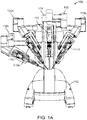
- Figures 1A , 1B , and 1C are front elevation views of three main components of a teleoperated robotic surgical system for minimally invasive surgery. These three components are interconnected so as to allow a surgeon, with the assistance of a surgical team, perform diagnostic and corrective surgical procedures on a patient.
- Fig. 1A is a front elevation view of the patient side cart component 100 of the da Vinci® Surgical System.
- the patient side cart includes a base 102 that rests on the floor, a support tower 104 that is mounted on the base 102, and several arms that support surgical tools (which include a stereoscopic endoscope).
- arms 106a,106b are instrument arms that support and move the surgical instruments used to manipulate tissue
- arm 108 is a camera arm that supports and moves the endoscope.
- Fig. 1A also shows an optional third instrument arm 106c that is supported on the back side of support tower 104 and that can be positioned to either the left or right side of the patient side cart as necessary to conduct a surgical procedure.
- Fig. 1A also shows an optional third instrument arm 106c that is supported on the back side of support tower 104 and that can be positioned to either the left or right side of the patient side cart as necessary to conduct a surgical procedure.
- 1A further shows interchangeable surgical instruments 110a,110b,110c mounted on the instrument arms 106a,106b,106c, and it shows endoscope 112 mounted on the camera arm 108.
- the arms are discussed in more detail below. Knowledgeable persons will appreciate that the arms that support the instruments and the camera may also be supported by a base platform (fixed or moveable) mounted to a ceiling or wall, or in some instances to another piece of equipment in the operating room (e.g., the operating table). Likewise, they will appreciate that two or more separate bases may be used (e.g., one base supporting each arm).
- Fig. 1B is a front elevation view of a surgeon's console 120 component of the da Vinci® Surgical System.
- the surgeon's console is equipped with left and right multiple DOF master tool manipulators (MTM's) 122a,122b, which are kinematic chains that are used to control the surgical tools (which include the endoscope and various cannulas).
- the surgeon grasps a pincher assembly 124a,124b on each MTM 122, typically with the thumb and forefinger, and can move the pincher assembly to various positions and orientations.
- each MTM 122 is coupled to control a corresponding instrument arm 106 for the patient side cart 100.
- left MTM 122a may be coupled to control instrument arm 106b and instrument 110a
- right MTM 122b may be coupled to control instrument arm 106b and instrument 110b. If the third instrument arm 106c is used during a surgical procedure and is positioned on the left side, then left MTM 122a can be switched between controlling arm 106a and instrument 110a to controlling arm 106c and instrument 110c. Likewise, if the third instrument arm 106c is used during a surgical procedure and is positioned on the right side, then right MTM 122a can be switched between controlling arm 106b and instrument 110b to controlling arm 106c and instrument 110c.
- control assignments between MTM's 122a,122b and arm 106a/instrument 110a combination and arm 106b/instrument 110b combination may also be exchanged. This may be done, for example, if the endoscope is rolled 180 degrees, so that the instrument moving in the endoscope's field of view appears to be on the same side as the MTM the surgeon is moving.
- the pincher assembly is typically used to operate a jawed surgical end effector (e.g., scissors, grasping retractor, needle driver, and the like) at the distal end of an instrument 110.
- Surgeon's console 120 also includes a stereoscopic image display system 126.
- Left side and right side images captured by the stereoscopic endoscope 112 are output on corresponding left and right displays, which the surgeon perceives as a three-dimensional image on display system 126.
- the MTM's 122 are positioned below display system 126 so that the images of the surgical tools shown in the display appear to be co-located with the surgeon's hands below the display. This feature allows the surgeon to intuitively control the various surgical tools in the three-dimensional display as if watching the hands directly. Accordingly, the MTM servo control of the associated instrument arm and instrument is based on the endoscopic image reference frame.
- the endoscopic image reference frame is also used if the MTM's are switched to a camera control mode.
- the surgeon may move the distal end of the endoscope by moving one or both of the MTM's together (portions of the two MTM's may be servomechanically coupled so that the two MTM portions appear to move together as a unit).
- the surgeon may then intuitively move (e.g., pan, tilt, zoom) the displayed stereoscopic image by moving the MTM's as if holding the image in the hands.
- the surgeon's console 120 is typically located in the same operating room as the patient side cart 100, although it is positioned so that the surgeon operating the console is outside the sterile field.
- One or more assistants typically assist the surgeon by working within the sterile surgical field (e.g., to change tools on the patient side cart, to perform manual retraction, etc.). Accordingly, the surgeon operates remote from the sterile field, and so the console may be located in a separate room or building from the operating room.
- two consoles 120 may be networked together so that two surgeons can simultaneously view and control tools at the surgical site.
- Fig. 1C is a front elevation view of a vision cart component 140 of the da Vinci® Surgical System.
- the vision cart 140 houses the surgical system's central electronic data processing unit 142 and vision equipment 144.
- the central electronic data processing unit includes much of the data processing used to operate the surgical system. In various other implementations, however, the electronic data processing may be distributed in the surgeon console and patient side cart.
- the vision equipment includes camera control units for the left and right image capture functions of the stereoscopic endoscope 112.
- the vision equipment also includes illumination equipment (e.g., Xenon lamp) that provides illumination for imaging the surgical site.
- the vision cart includes an optional 24-inch (61 cm) touch screen monitor 146, which may be mounted elsewhere, such as on the patient side cart 100.
- the vision cart 140 further includes space 148 for optional auxiliary surgical equipment, such as electrosurgical units and insufflators.
- auxiliary surgical equipment such as electrosurgical units and insufflators.
- the patient side cart and the surgeon's console are coupled via optical fiber communications links to the vision cart so that the three components together act as a single teleoperated minimally invasive surgical system that provides an intuitive telepresence for the surgeon.
- a second surgeon's console may be included so that a second surgeon can, e.g., proctor the first surgeon's work.
- Fig. 2A is a side elevation view of an illustrative instrument arm 106.
- the arm is made of a series of links and joints that couple the links together.
- the arm is divided into two portions. The first portion is the "set-up" portion 202, in which unpowered joints couple the links.
- the second portion is powered, robotic manipulator portion 204 (patient side manipulator; "PSM”) that supports and moves the surgical instrument.
- PSM patient side manipulator
- the set-up portion 202 is moved to place the manipulator portion 204 in the proper position to carry out the desired surgical task.
- the set-up portion joints are then locked (e.g., with brake mechanisms) to prevent this portion of the arm from moving.
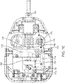
- Fig. 2B is a perspective view of the PSM 204 with an illustrative instrument 110 mounted.
- the PSM 204 includes a yaw servo actuator 206, a pitch servo actuator 208, and an insertion and withdrawal ("I/O") actuator 210.
- An illustrative surgical instrument 110 is shown mounted at an instrument mounting carriage 212.
- An illustrative straight cannula 214 is shown mounted to cannula mount 216.
- Shaft 218 of instrument 110 extends through cannula 214.
- PSM 204 is mechanically constrained so that it moves instrument 110 around a stationary remote center of motion 220 located along the instrument shaft.
- Yaw actuator 206 provides yaw motion 222 around remote center 220
- pitch actuator 208 provides pitch motion 224 around remote center 220
- I/O actuator 210 provides insertion and withdrawal motion 226 through remote center 220.
- the set up portion 202 is typically positioned to place remote center of motion 220 at the incision in the patient's body wall during surgery and to allow for sufficient yaw and pitch motion to be available to carry out the intended surgical task.
- Knowledgeable persons will understand that motion around a remote center of motion may also be constrained solely by the use of software, rather than by a physical constraint defined by a mechanical assembly.
- Matching force transmission disks in mounting carriage 212 and instrument force transmission assembly 230 couple actuation forces from actuators 232 in PSM 204 to move various parts of instrument 110 in order to position, orient, and operate instrument end effector 234.
- Such actuation forces may typically roll instrument shaft 218 (thus providing another DOF through the remote center), operate a wrist 236 that provides yaw and pitch DOF's, and operate a movable piece or grasping jaws of various end effectors (e.g., scissors (cautery or non-cautery capable), dissectors, graspers, needle drivers, electrocautery hooks, retractors, clip appliers, etc.).
- Fig. 2C is a side elevation view of a portion of a camera arm 108 with an illustrative camera 112 mounted. Similar to the instrument arm 106, the camera arm 108 includes a set-up portion 240 and a manipulator portion 242 (endoscopic camera manipulator; "ECM"). ECM 242 is configured similarly to PSM 204 and includes a yaw motion actuator 244, a pitch motion actuator 246, and an I/O motion actuator 248. Endoscope 112 is mounted on carriage assembly 250, and endoscope cannula 252 is mounted on camera cannula mount 254. ECM 242 moves endoscope 112 around and through remote center of motion 256.
- ECM endoscopic camera manipulator
- incisions are made into the patient's body (usually with the use of a trocar to place the associated cannula).
- One incision is for the endoscope camera instrument, and the other incisions are for the necessary surgical instruments.
- Such incisions are sometimes referred to as "ports", a term which may also mean a piece of equipment that is used within such an incision, as described in detail below.
- several instrument and/or camera ports are necessary in order to provide the needed access and imaging for a surgical site.
- the incisions are relatively small in comparison to larger incisions used for traditional open surgery, there is the need and desire to further reduce the number of incisions to further reduce patient trauma and for improved cosmesis.
- Single port surgery is a technique in which all instruments used for minimally invasive surgery are passed through a single incision in the patient's body wall, or in some instances through a single natural orifice.
- Such methods may be referred to by various terms, such as Single Port Access (SPA), Laparo Endoscopic Single-site Surgery (LESS), Single Incision Laparoscopic Surgery (SILS), One Port Umbilical Surgery (OPUS), Single Port Incisionless Conventional Equipment-utilizing Surgery (SPICES), Single Access Site Surgical Endoscope (SASSE), or Natural Orifice TransUmbilical Surgery (NOTUS).
- SPA Single Port Access
- LESS Laparo Endoscopic Single-site Surgery
- SIFS Single Incision Laparoscopic Surgery
- OPUS One Port Umbilical Surgery
- SPICES Single Port Incisionless Conventional Equipment-utilizing Surgery
- SASSE Single Access Site Surgical Endoscope
- NOTES Natural Orifice TransUmbilical Surgery
- the use of a single port may done using either manual instruments or a robotic surgical system, such
- Two instruments, for example, are positioned nearly side-by-side, and so it is difficult to achieve advantageous triangulation angles at the surgical site (triangulation being the ability for the distal ends of two surgical instruments to be positioned along two legs of a triangle to work effectively at a surgical site at the apex of the triangle).
- triangulation being the ability for the distal ends of two surgical instruments to be positioned along two legs of a triangle to work effectively at a surgical site at the apex of the triangle).
- straight instrument shafts tend to obscure a large part of the endoscope's field of view.
- the multiple manipulators may interfere with one another, due to both their size and their motions, which also limits the amount of end effector movement available to the surgeon.
- Fig. 3 illustrates the difficulty of using a multi-arm robotic surgical system for single port surgery.
- Fig. 3 is a diagrammatic view of multiple cannulas and associated instruments inserted through a body wall so as to reach a surgical site 300.
- a camera cannula 302 extends through a camera incision 304
- a first instrument cannula 306 extends through a first instrument incision 308
- a second instrument cannula 310 extends through a second instrument incision 312.
- Fig. 4A is a schematic view of a portion of a patient side robotic manipulator that supports and moves a combination of a curved cannula and a passively flexible surgical instrument.
- a telerobotically operated surgical instrument 402a includes a force transmission mechanism 404a, a passively flexible shaft 406a, and an end effector 408a.
- Instrument 402a is mounted on an instrument carriage assembly 212a of a PSM 204a (previously described components are schematically depicted for clarity).
- Interface discs 414a couple actuation forces from servo actuators in PSM 204a to move instrument 402a components.
- End effector 408a illustratively operates with a single DOF (e.g., closing jaws).
- a wrist to provide one or more end effector DOF's e.g., pitch, yaw; see e.g., U.S. Patent No. 6,817,974 (filed Jun. 28, 2002 ) (disclosing "Surgical Tool Having Positively Positionable Tendon-Actuated Multi-Disk Wrist Joint"
- end effector DOF's e.g., pitch, yaw; see e.g., U.S. Patent No. 6,817,974 (filed Jun. 28, 2002 ) (disclosing "Surgical Tool Having Positively Positionable Tendon-Actuated Multi-Disk Wrist Joint"
- Many instrument implementations do not include such a wrist.
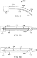
- Fig. 4A further shows a curved cannula 416a, which has a proximal end 418a, a distal end 420a, and a central channel 422a that extends between proximal end 418a and distal end 420a.
- Curved cannula 416a is, in one implementation, a rigid, single piece cannula.
- proximal end 418a of curved cannula 416a is mounted on PSM 204a's cannula mount 216a.
- instrument 402a's flexible shaft 406a extends through curved cannula 416a's central channel 422a so that a distal portion of flexible shaft 406a and end effector 408a extend beyond cannula 416a's distal end 420a in order to reach surgical site 424.
- PSM 204a's mechanical constraints or, alternately, preprogrammed software constraints in the control system for PSM 204a cause instrument 402a and curved cannula 416a to move in pitch and yaw around remote center of motion 426 located along cannula 416a, which is typically placed at an incision in the patient's body wall.
- PSM 204a 's I/O actuation, provided by carriage 212a, inserts and withdraws instrument 402a through cannula 416a to move end effector 408a in and out. Details of instrument 402a, cannula 416a, and the control of these two components is described below.
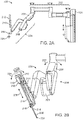
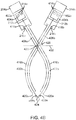
- Fig. 4B is a schematic view that shows a second patient side robotic manipulator that supports and moves a second curved cannula and passively flexible surgical instrument combination, added to the Fig 4A view.
- Components of the second PSM 204b, instrument 402b, and curved cannula 416b are substantially similar to, and function in a substantially similar manner to, those described in Fig. 4A .
- Curved cannula 416b curves in a direction opposite to the direction in which curved cannula 416a curves.
- FIG. 4B thus illustrates that two curved cannulas and associated instruments, curving in opposite directions, are positioned to extend through a single incision 428 in the patient's body wall 430 to reach surgical site 424.
- Each curved cannula initially angles away from a straight line between the incision and the surgical site and then curves back towards the line to direct the extended instruments to the surgical site.
- the distal ends 420a,420b of the curved cannulas move accordingly, and therefore instrument end effectors 404a and 404b are moved with reference to the surgical site (and consequently, with reference to the endoscope's field of view). It can be seen that although the remote centers of motion for the two curved cannula and flexible instrument combinations are not identical, they are sufficiently close enough (proximate) to one another so that they can both be positioned at the single incision 428.
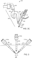
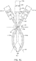
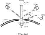
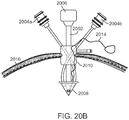
- Fig. 4C is a schematic view that shows an endoscopic camera manipulator that supports an endoscope, added to the Fig. 4B view. Some previously used reference numbers are omitted for clarity.
- ECM 242 holds endoscope 112 such that it extends through single incision 428, along with the two curved cannula and flexible instrument combinations. Endoscope 112 extends through a conventional cannula 252 supported by cannula mount 254. In some implementations, cannula 252 provides insufflation to a body cavity. ECM 242 is positioned to place the endoscope 112's remote center of motion at incision 428.
- the remote centers of motion for the two curved cannula and instrument combinations and the endoscope 112 are not identical, but they may be positioned sufficiently close to allow all to extend through the single incision 428 without the incision being made unduly large.
- the three remote centers may be positioned on approximately a straight line, as illustrated in Fig 4C .
- the remote centers are not linearly aligned, yet are grouped sufficiently close.
- Fig. 4C also schematically illustrates that the PSM's 204a,204b and the ECM 242 may be positioned so that each has a significantly improved volume in which to move in pitch and yaw without interfering with each other. That is, if straight-shaft instruments are used, then the PSM's must in general remain in positions near one another to keep the shafts in a near parallel relation for effective work through a single incision. But with the curved cannulas, however, the PSM's can be placed farther from one another, and so each PSM can in general move within a relatively larger volume than with the straight-shaft instruments. In addition, Fig. 4C illustrates how the curved cannulas 416 provide an improved triangulation for the surgical instruments, so that the surgical site 426 is relatively unobstructed in endoscope 112's field of view 430.
- Fig. 4C further illustrates that a port feature 432 may be placed in incision 428.
- Cannulas 416a, 416b, and 252 each extend through port feature 432.
- Such a port feature may have various configurations, as described in detail below.
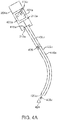
- Fig. 5 is a diagrammatic view of an illustrative flexible instrument 500 used with a curved cannula.
- Instrument 500 includes a proximal end force transmission mechanism 502, a distal end surgical end effector 504, and a shaft 506 that couples force transmission mechanism 502 and end effector 504.
- shaft 506 is about 43 cm long.
- shaft 506 is passively flexible and includes three sections-a proximal section 506a, a distal section 506c, and a middle section 506b that is between proximal and distal sections 506a,506c.
- the sections 506a,506b,506c may be each characterized by their different stiffnesses.
- Section 506a is the portion of shaft 506 that extends from force transmission mechanism 502 towards the curved cannula through which the other sections of shaft 506 extend. Consequently, section 506a is relatively stiff in comparison to the other sections 506b,506c. In some implementations, section 506a may be effectively rigid. Section 506b is relatively more flexible than the other two sections 506a,506c.
- section 506b The majority of section 506b is within the curved cannula during a surgical procedure, and so section 506b is made relatively flexible to reduce friction with the inner wall of the curved cannula, yet it is not made so flexible so that it buckles during insertion under manual or servocontrolled operation.
- Section 506c is relatively more stiff than section 506b, because section 506c extends from the distal end of the curved cannula. Accordingly, section 506c is made flexible enough so that it may be inserted through the bend of the curved cannula, yet it is made rigid enough to provide adequate cantilever support for end effector 504.
- shaft sections 506a-506c each have the same physical structure-each being composed of the same material(s), and the material(s) chosen to have a bending stiffness acceptable for each section-so the sections thus have the same stiffness.
- Such instrument shafts are generally lower cost because, e.g., they have fewer parts and are easier to assemble.
- the stiffness of the instrument shaft (or at least the portion of the shaft that moves within the cannula), with an outer material selected to reasonably minimize shaft friction within the cannula, is close to the maximum that the robot can insert and roll.
- Such insertion and roll forces are substantially more than forces that can be reasonably controlled by a human, and so the stiffness of the instrument's distal section that extends from the distal end of the cannula can be made substantially higher than hand-operated instrument shaft stiffness would be for a similar but manually actuated curved cannula system.
- the instrument shaft is "tuned" (e.g., by selecting one or more particular materials and/or by various shaft constructions using the selected material(s)) to (i) make effective use of the robot's insertion and roll drive capabilities with reasonably stiff shafts while (ii) not allowing the friction between such reasonably stiff shafts and a particular cannula curve dimension to offset the robot's drive capability benefits.
- certain instruments may have flexible shafts of one stiffness for use with cannulas with one curve radius and/or inner diameter
- other instruments may have shafts of another stiffness for use with cannulas with another curve radius and/or inner diameter.
- shaft stiffness for an instrument designed for use with a cannula having a relatively larger curve radius may be larger than shaft stiffness for an instrument designed for use with a cannula having a relatively smaller curve radius.
- the shaft's lateral (bending) stiffness is in a range from about 1 lb-in 2 (PSI ⁇ in 4 ) to about 4 lb-in 2 , and in one implementation the shaft's lateral stiffness is about 2.0 lb-in 2 .
- the shaft's rotational stiffness is larger than about 11 lb-in 2 , and in one implementation the shaft's rotational stiffness is about 22.0 lb-in 2 .
- a practical range of rotational stiffness is in the range of about 11 lb-in 2 to about 66 lb-in 2 .
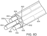
- instrument shaft stiffness must also decrease. If an isotropic material is used for the instrument shaft, such as is illustrated in association with Figs. 8C and 8D , then the stiffness of the shaft portion that extends from the cannula's distal end is also reduced. At some point, either the stiffness of the shaft's extended distal end or the stiffness of the shaft portion between the transmission mechanism and the cannula may become unacceptably low. Therefore, as described above, a range of stiffnesses may be defined for an isotropic material shaft of fixed dimensions, depending on a cannula's bend radius and inner diameter.
- Surgical instrument end effectors placed at the distal end of the flexible shaft instruments are of two general types.
- the first type of end effector has no moving parts.
- Such non-moving end effectors may include, for example, suction/irrigation tips, electrocautery hooks or blades, probes, blunt dissectors, cameras, retractors, etc.
- the second type of end effector has at least one moving component that is actuated under robotic control.
- Such moving component end effectors include, for example, graspers, needle drivers, moving cautery hooks, clip appliers, shears (both non-cautery and cautery), etc.
- the one or more moving end effector components may be actuated in various ways.
- two tension elements may be used to actuate an end effector component.
- one tension element moves the end effector component in one direction
- the second tension element moves the component in the opposite direction.
- a single compression/tension element is used to move the end effector component.
- pulling (tension) is used to move the component in one direction
- pushing (compression) is used to move the component in the opposite direction.
- the tension force is used to actuate the end effector component in the direction that requires the highest force (e.g., closing jaws).
- Fig. 6A is a diagrammatic view that illustrates aspects of a pull/pull instrument design.
- an instrument force transmission mechanism 602 is coupled to a grip-type end effector 604 by a flexible shaft body 606.
- a tension element 608 is routed through shaft body 606 and couples a movable component in end effector 604 to a component (not shown; see below) in transmission mechanism 602 that receives a robotic actuation force.
- Tension element 608 is routed through a force isolation component 610 that is coupled between the base 612 of the end effector and backing plate 614 in transmission mechanism 602.
- shaft body 606 is a plastic tube (e.g., polyaryletheretherketone (PEEK))
- tension element 608 is a hypotube (e.g., 316 Stainless Steel (face hardened), 0.028-inch OD ⁇ 0.020 ID, i.e. .0,7112-mm OD X 0,508 ID, with polytetrafluoroethylene (PTFE) dip coating) with cables (e.g., 0.018-inch (0,4572 mm) tungsten) at each end that are coupled to the transmission mechanism and end effector components
- force isolation component 610 is a coil tube (e.g., 300 series stainless steel).
- shaft body 606 does not experience the tension load on tension element 608 that moves the end effector component, because the tension force is offset by an equal and opposite reaction force in isolation component 610. Consequently, two such tension element and force isolation component pairs within shaft body tube 606 can be used for a pull/pull end effector actuation design, the instrument shaft remains flexible with no effective change in its designed stiffness or bend during pull/pull actuation, and the tension load on tension element 608 is effectively independent of shaft body 606 bending.
- 304V vacuum arc remelt
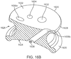
- Fig. 6B is a diagrammatic view that illustrates aspects of a push/pull instrument design.
- an instrument force transmission mechanism 620 is coupled to a grip-type end effector 622 by a flexible shaft body 624.
- a compression/tension drive element 626 is routed through shaft body 624 and couples a movable component in end effector 622 to a component (not shown; see below) in transmission mechanism 620 that receives a robotic actuation force.
- One or more force isolation components 628 are also routed through shaft body 624 and are coupled to the base 630 of the end effector and to a backing plate 632 in the force transmission mechanism.
- shaft body 624 is a plastic tube (e.g., PEEK), drive element 626 is a solid rod (e.g., 304V Stainless Steel, 0.032-inch (0,8128 mm) OD with PTFE spray coating), and force isolation components 628 are also solid rods (e.g., 304V Stainless Steel, 0.032-inch (0,8128 mm) OD with PTFE spray coating). It can be seen that shaft body 624 does not experience either the compression or tension loads on drive element 626 that moves the end effector component, because the drive forces are offset by equal and opposite reaction forces in isolation components 628.
- PEEK plastic tube
- drive element 626 is a solid rod (e.g., 304V Stainless Steel, 0.032-inch (0,8128 mm) OD with PTFE spray coating)
- force isolation components 628 are also solid rods (e.g., 304V Stainless Steel, 0.032-inch (0,8128 mm) OD with PTFE spray coating).
- the instrument shaft remains flexible with no effective change in its designed stiffness or bend during push/pull actuation, and the drive loads on drive element 626 are effectively independent of shaft body 624 bending.
- the force isolation components 628 can act to effectively increase the instrument shaft's bending stiffness a desired value.
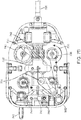
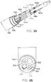
- Fig. 7A is a bottom view of an implementation of force transmission mechanism 502.
- the force transmission mechanism of a surgical instrument used in a da Vinci® Surgical System has been modified to eliminate the mechanisms used to control a wrist mechanism on the instrument and to control the jaw of an end effector (or other moveable part) using only a single interface disk.
- one interface disk 702a rolls shaft 506 so as to provide a roll DOF for end effector 504, and a second interface disk 702b operates end effector 504's jaw mechanism.
- a bulkhead in transmission mechanism 502 supports coil tubes that run through the instrument shaft, as described in detail above and below.
- Force transmission mechanism 502 may be coupled to PSM 204 without any mechanical modifications required to the PSM, a feature that minimizes implementation costs of curved cannula aspects in existing robotic surgical systems.
- Fig. 7A also shows that implementations of force transmission mechanism 502 may include electrically conductive interface pins 704 and an electronic data memory 706 that is electrically coupled to interface pins 704.
- Parameters relevant to instrument 500 and its operation e.g., number of times the instrument has been used, Denavit-Hartenberg parameters for control (described below), etc.
- Parameters relevant to instrument 500 and its operation may be stored in memory 706 and accessed by the robotic surgical system during operation to properly use the instrument (see e.g., U.S. Patent No. 6,331,181 (filed Oct. 15, 1999 ) (disclosing surgical robotic tools, data architecture, and use).
- kinematic data specific to the curved cannula through which the instrument extends may also be stored in memory 706, so that if the system detects that a curved cannula is mounted (see e.g., Fig. 10 and associated text below), the system may access and use the stored cannula data. If more than one curved cannula kinematic configuration (e.g., different lengths, bend radii, bend angles, etc.) is used, then data specific to each allowable configuration may be stored in the associated instrument's memory, and the system may access and use data for the specific cannula configuration that is mounted. In addition, in some instances if the robotic surgical system senses that a flexible instrument has been coupled to a manipulator that holds a straight, rather than curved, cannula, then the system may declare this situation to be an illegal state and prevent operation.
- a curved cannula kinematic configuration e.g., different lengths, bend radii, bend angles, etc.
- Fig. 7B is a plan view of an illustrative implementation of a force transmission mechanism used in a pull/pull instrument design. As shown in Fig. 7B , two coil tubes 730 are positioned against backing plate 732. Two tension elements 734 extend from the coil tubes, through the backing plate, and are routed to open/close capstan 736, which rotates as indicated by arrows 738 to pull on one or the other of the tension elements.
- Fig. 7B also depicts an illustrative implementation of shaft roll-cross-connected helical drive gear 740 and shaft roll gear 742. Roll gear 742 is coupled (e.g., laser welded) to a stainless steel adaptor swaged over the proximal end of the flexible shaft's body tube.
- Fig. 7B further depicts an illustrative monopolar electrocautery energy connection 744 between plug 746 and electrically conductive tension elements 734. And, Fig. 7B depicts an illustrative positioning of a memory chip 748 that contains instrument and/or associated cannula data, as described herein, and the chip's associated electrical contacts 750 that connect with the surgical system through mating contacts on the PSM.
- Fig. 7C is a plan view of an illustrative implementation of a force transmission mechanism used in a push/pull instrument design.
- force isolation rods 760 extend out of the proximal end of the flexible instrument shaft and are joined with backing plate 762.
- Push/pull drive element rod 764 also extends out of the proximal end of the instrument shaft, and further extends through backing plate 762 to be coupled with slider 766.
- drive element rod 764 is coupled with linear slider 766 using a free rolling bearing 768. This free rolling bearing prevents the drive rod from twisting when the instrument shaft is rolled (i.e., provides an unconstrained roll DOF).
- Push/pull drive gear 770 is engaged with lever gear 772.
- Lever gear 772 is coupled to slider 766 with link (offset crank) 774.
- link (offset crank) 774 As drive gear 770 turns back and forth as indicated by arrows 776, slider 766 slides along shaft 778 as indicated by arrows 780, thus moving drive element 764 along the instrument shaft's longitudinal axis.
- the Fig. 7C shaft roll implementation is substantially similar to the implementation described above with reference to Fig. 7B .
- Fig. 7C also shows an illustrative flush fluid entry port 790 at the proximal end of the instrument shaft.
- the flush fluid port is made part of the assembly that couples the shaft body tube to the roll gear.
- Flush fluid may be directed into the port to clean components inside the shaft. For example, even though an actuating drive rod or cable may extend through a wipe seal at the distal end of the shaft, a small amount of body fluid may pass the seal and enter the inside of the shaft body.
- Fig. 7D is a perspective view of another illustrative implementation of a force transmission mechanism used in a push/pull instrument design.
- two pinion drive gears 782 engage a rack gear 784 between them.
- the rack is round, and a flat rack may be used instead.
- the push/pull drive element rod is coupled to the rack (e.g., with a free rolling bearing as described above).
- the implementation depicted in Fig. 7D uses two extra drive elements and associated interface disks (not shown; see e.g., Fig. 7A ) positioned towards the rear of the force transmission mechanism, and the drive elements rotate in opposite directions to move the rack along the instrument shaft's longitudinal axis.
- This implementation design uses fewer parts, and so is less expensive and simpler to manufacture than the implementation shown in Fig. 7C , although this Fig. 7D implementation does use an extra drive element in the force transmission mechanism's interface to the robotic manipulator.
- An advantage of using more than one drive element, however, is that the mechanism can exert more force in comparison to using only a single, comparable drive element (e.g., effectively two times as much if two drive elements are used).
- Fig. 8A is a cutaway perspective view that shows an illustrative structure of a portion of instrument shaft 506.
- Two tension elements 802a,802b extend through a distal portion of shaft 506 and are coupled to operate the end effector (shown diagrammatically; e.g., a 5 mm diameter class surgical end effector used in da Vinci® Surgical System instruments).
- Tension elements 802a,802b may be separate, or they may be parts of the same element that, for example, wraps around a pulley in the end effector.
- tension elements 802a,802b are 0.018-inch (0,4572 mm) tungsten wire. As shown in Fig.
- tension elements 802a,802b are coupled (e.g., crimped, etc.) to distal ends of second tension elements 804a,804b that further extend proximally through most of shaft 506.
- tension elements 804a,804b are 0.032-inch (0,8128 mm) stainless steel hypotubes.
- tension elements 804a,804b are coupled to transmission mechanism 502 using wires coupled in a similar manner, as described above.
- tension elements 804a,804b extend through support tubes 806a,806b respectively, which guide tension elements 804a,804b and keep them from buckling or kinking within shaft 506.
- support tubes 806a,806b are stainless steel (e.g., 304V (vacuum melt that reduces friction)) coil tubes (0.035-inch (0,889 mm) inner diameter; 0.065-inch (1,651 mm) outer diameter), and other materials and structures may be used.
- a friction reducing sheath 808a,808b is placed between the tension element and the inner wall of the support tube.
- sheaths 808a,808b are PTFE, and other materials may be used. Both support tubes 806a,806b are placed within a single inner shaft tube 810. In one implementation, a flat-spiral stainless steel wire is used for inner shaft tube 810 to provide torsional stiffness during roll.
- An outer shaft tube 812 e.g., braided stainless steel mesh or other material suitable to protect the shaft components
- An elastomer skin 814 e.g., Pellothane®, or other suitable material surrounds the outer shaft tube 812.
- Skin 814 protects the inner components of shaft 506 from direct contamination by, e.g., body fluids during surgery, and the skin facilitates shaft 506 sliding within the curved cannula.
- shaft 506 is approximately 5.5 mm (0.220 inches) outer diameter.
- the support tube and tension element assemblies may be dip coated in PTFE to provide a "sheath" that reduces friction.
- the space between the coils is filled in by the dip coating material to form a tube.
- wire is pre-coated before the coil is wound, and the coil is then baked to re-melt the coating and form the solid tube.
- the ends of the tube may be sealed around the tension elements to prevent contamination (e.g., body fluids) from entering between the tension element and the coil tube.
- Shaft 506 may include additional components.
- one or more stiffening rods 816 run through various portions of shaft 506.
- the number, size, and composition of rods 816 may be varied to provide the various stiffnesses of portions 506a-506c, as described above.
- rods 816 are stainless steel.
- one or more additional rods 818 of another material may run through one or more portions of shaft 506.
- Fig. 8A shows a second rod of PEEK that in one implementation runs through distal section 506c to provide stiffness in addition to the stiffness from rods 516.
- one or more supplemental tubes to provide, e.g., suction and/or irrigation or flushing for cleaning may be included in shaft 506, either in addition to or in place of the stiffening rods.
- additional tension elements may be included to operate, e.g., an optional multi-DOF wrist mechanism at the distal end of the instrument shaft.
- Fig. 8B is a cross-sectional diagrammatic perspective view of another implementation of an instrument shaft design.
- two hypotube tension elements 820 with PTFE coating are positioned within force isolation coil tubes 822.
- An optional fluorinated ethylene propylene (FEP) insulation layer may surround the coil tubes.
- a PEEK body tube 824 surrounds the tension elements and coil tubes, and an FEP heat shrink skin 826 surrounds the body tube.
- An optional flush tube 828 may be placed inside body tube 824, and it is configured so that cleaning fluid from the proximal end of the shaft travels through the cleaning tube to the distal end of the shaft, and then back through the body tube to flush out, e.g., contaminating body fluids.
- the instrument materials are selected, nevertheless, to allow the instrument to be autoclavable for sterilization.
- Fig. 8C is a cutaway perspective view that shows another illustrative structure of a portion of instrument shaft 506.
- Tension elements 830a, 830b, 832a, and 832b are similar to tension elements 802a, 802b, 804a, and 804d described above.
- the tension elements are each routed through individual channels in multi-channel support tube 834.
- tube 834 is a FEP extrusion with multiple channels 836, and other materials may be used. FEP provides a low-friction surface against which the tension elements slide.
- One or more stiffening rods (not shown) similar to those disclosed above may be routed through various other channels 836 in support tube 834 to provide desired stiffnesses for each of the instrument shaft sections 506a-506c.
- a seven-channel tube 834 (six channels arranged around a central channel) is shown in Fig. 8C , and a stiffening rod or other element may be inserted into the center channel. Additional cables, e.g., to operate an optional multi-DOF wrist mechanism at the distal end of shaft 506, may be routed through other channels in tube 834. Alternatively, other functions, such as suction and/or irrigation, may be provided through the channels.
- Fig. 8C further shows a shaft body tube 838 (e.g., extruded PEEK or other suitable material) surrounding support tube 834 to provide axial and torsional stiffness to shaft 506.
- An outer skin or coating 840 surrounds body tube 838 to reduce friction as shaft 506 slides inside the curved cannula and to protect the shaft components.
- skin 840 is a 0.005-inch (0,127 mm) layer of FEP that is heat shrunk around body tube 838, and other suitable materials may be used.
- Fig. 8C further shows a shaft body tube 838 (e.g., extruded PEEK or other suitable material) surrounding support tube 834 to provide axial and torsional stiffness to shaft 506.
- An outer skin or coating 840 surrounds body tube 838 to reduce friction as shaft 506 slides inside the curved cannula and to protect the shaft components.
- skin 840 is a 0.005-inch (0,127 mm) layer of FEP that is heat shrunk around body
- the shaft 506 outer diameter is approximately 5.5 mm (0.220 inches), with a single extrusion PEEK body tube having an outer diameter of approximately 5.0 mm and an inner diameter of about 3.5 mm.
- PEEK is used because its stiffness (modulus of elasticity, or Young's modulus) is low enough to allow bending with low enough radial force to limit friction inside the curved cannula so that instrument I/O is not affected in a meaningful way, but its modulus of elasticity is high enough to provide good cantilever beam stiffness for the shaft distal portion 506c that extends beyond the distal end of the curved cannula, to resist buckling of any portion of the shaft between the transmission mechanism and the proximal end of the cannula, and to transmit roll motion and torque along the length of the instrument shaft with adequate stiffness and precision.
- Fig. 8D is a diagrammatic transparent perspective view that shows yet another implementation a flexible instrument shaft design.
- a push/pull drive element 850 extends through a center channel 852 in a multi-channel tube 854, which is similar to tube 834 described above.
- Three force isolation/stiffening rods 856 as described above extend through three of the channels 858 surrounding the center channel.
- the distal ends of the rods 856 include stainless steel plugs that fit into the channels.
- the remaining three channels 860 surrounding the center channel are left open and are used as flush fluid channels. In other implementations, however, other elements may be routed through one or more of the channels 860.
- the surrounding instrument shaft body tube and skin are omitted from the drawing for clarity.
- Fig. 9A is an exploded perspective view of an implementation of the distal end of a flexible shaft instrument.
- two coil tubes 902 are coupled to distal end cap 904.
- the coil tubes are positioned inside body tube 906 with outer skin 908 as described above (the tension elements are not shown).
- a tension element seal 910 is fitted into end cap 904, and the tension elements extend through seal 910, which keeps fluids from entering into the coil tubes.
- seal 910 is a molded silicone wipe seal.
- Adaptor cap 912 is positioned over the distal end of the body tube, and the end effector clevis 914 is coupled to the adaptor cap.
- Fig. 9B is a cross-sectional view of the implementation depicted in Fig. 9A .
- end cap 904 includes ridges 916 that enable the cap to be swaged inside body tube 906.
- Coil tubes 902 are positioned against cap 904, and tension element cables 918 are routed through cap 904 and seal 910.
- Adaptor cap 912 is swaged over body tube 906, and in the illustrative implementation is tapered to allow FEP heatshrink skin 908 to cover a portion of cap 912.
- End effector clevis 914 is coupled (e.g., laser welded) to adaptor cap 912.
- a single clevis and adapter cap piece may be substituted for the cap 912 and clevis 914. The single piece reduces manufacturing cost and complexity by eliminating the laser weld.
- Fig. 9C is a diagrammatic view that illustrates a pull/pull type end effector that may be at the distal end of the flexible shaft instruments. As depicted in Fig. 9C , pulling on one cable opens the end effector jaws, and pulling on the other cable closes the end effector jaws.
- Fig. 9D is an exploded perspective view of another implementation of the distal end of a flexible shaft instrument.
- end cap 920 fits inside the distal end of shaft body tube 922.
- Wipe seal 924 covers the opening in end cap 920, and push/pull drive rod connector 926 extends through end cap 920 and seal 924 to couple with the movable component of the end effector.
- End effector clevis and attachment cap assembly 928 fits over the end of shaft body tube 922.
- the components are assembled in a manner similar to that described in relation to Fig. 9B (e.g., the use of swaging, etc.).
- the opening in seal 924 for the drive rod connector is slightly undersized, and compressing the seal before swaging assembly 928 to the shaft body tube further closes the seal around the drive rod connector.
- Fig. 9E is a diagrammatic view that illustrates a push/pull type end effector that may be at the distal end of the flexible shaft instruments (an illustrative clip applier end effector is shown). As depicted in Fig. 9E , pushing on the drive rod closes the end effector jaws, and pulling on the drive rod opens the end effector jaws.
- Fig. 9F is a diagrammatic perspective view of an implementation of an end cap designed to facilitate cleaning.
- Two coil tubes as described above are joined with the end cap at openings 940.
- Two flush fluid tubes as described above are joined with the end cap at openings 942.
- An elongate bore 944 is placed in the end cap to intersect each of the openings 940,942. The ends of the bore are sealed by the swage connection between the end cap and the body tube, and so a chamber is formed (the swage ridges are omitted from the drawing for clarity).
- Fluid for cleaning travels distally through the instrument shaft via the flush tubes, enters the chamber, and is redirected proximally through the interiors of the coil tubes for cleaning.
- a distal end chamber receives cleaning fluid through one or more channels in a multi-channel support tube and redirects the fluid through the center channel to flush away contaminates for cleaning.
- Fig. 10 is a diagrammatic view of an illustrative curved cannula 416.
- cannula 416 includes a mounting section 1002 and cannula body section 1004.
- the mounting section 1002 is configured to be mounted on a robotic system manipulator (e.g., PSM 204).
- PSM 204 a robotic system manipulator
- one or more features 1006 are placed on the mounting section 1002 to be sensed by sensors 1008 in the manipulator's cannula mount.
- the presence of a feature 1006 as sensed by the sensors 1008 may indicate, e.g., that the cannula is properly mounted and the type of cannula (e.g., straight or curved, cannula length, curve radius, etc.).
- the features 1006 are raised annular metal rings and the corresponding sensors 1008 are Hall effect sensors.
- Mounting section 1002 may also include a mechanical key feature 1009 that mates with a corresponding feature on the manipulator to ensure that the cannula is mounted with the proper orientation with reference to the manipulator's insertion axis. In this way, for example, “left” and “right” curving cannulas may be made. In addition, to distinguishing left versus right curve orientation, the keyed feature may be used to ensure that the cannula is rolled at the proper angle in the manipulator mount so that instruments approach the surgical site at a desired angle.
- mechanical key features may be used (e.g., mating pins/holes, tabs/grooves, balls/detents, and the like).
- FIG. 10A illustrates one example key feature.
- key feature 1030 is attached (e.g., welded) to the side of a mounting bracket 1032 for a curved cannula.
- Key feature 1030 includes a recess 1034 that receives a portion of a robotic manipulator's cannula mounting bracket and two vertical alignment pins 1036a and 1036b. Alignment pins 1036a and 1036b mate with corresponding alignment holes in the manipulator's mounting bracket to ensure the cannula's proper roll orientation with reference to the manipulator.
- Figs. 11A and 11B are diagrammatic views of the distal ends 1102a and 1102b of two curved cannulas as a surgeon might see them in the surgeon's console's 3-D display 1104, which outputs images captured in the endoscope's field of view.
- the curved cannulas extend away from the endoscope to enable the instruments 1106a and 1106b to reach tissue 1108 at the surgical site.
- the cannulas may be mounted on the manipulators at various roll angles, or the manipulators may be oriented during surgery, so that the instruments approach the surgical site at various angles. Accordingly, the cannula roll orientations may described in several ways. For example, the cannula roll angles may be described in relation to each other. Fig.
- FIG. 11A shows that in one implementation the cannulas may be oriented with their distal curves lying approximately in a single common plane, so that the instruments extend from directly opposite angles towards the surgical site.
- Fig. 11B shows that in one implementation the cannulas may be oriented with their distal curves lying in planes that are angled with reference to each other, e.g., approximately 60 degrees as shown, so that the instruments extend from offset angles towards the surgical site.
- Many cannula curve plane relation angles are possible (e.g., 120, 90, 45, 30, or zero degrees).
- cannula roll orientation is to define it as the angle between the plane that includes the cannula's curve and a plane of motion for one of the manipulator's degrees of freedom (e.g., pitch).
- a cannula may be mounted so that its curve lies in a plane that is angled at 30 degrees to the manipulator's pitch DOF.
- Fig. 11B is a plan view of a da Vinci® Surgical System in an illustrative configuration in which two PSM's 204 and the ECM 242 are posed to place curved cannulas 416 as described above with reference to Fig. 11B . It can be seen in Fig.
- the PSM's with curved cannulas have a reasonably large volume in which they can move without collision, which provides a correspondingly larger volume in which the instruments can move at the surgical site.
- cannula body section 1004 is in some implementations divided into a proximal section 1004a, a middle section 1004b, and a distal section 1004c.
- Proximal section 1004a is straight, and its length is made sufficient to provide adequate movement clearance for the supporting PSM.
- Middle section 1004b is curved to provide the necessary instrument triangulation to the surgical site from a manipulator position that provides sufficient range of motion to complete the surgical task without significant collisions.
- middle section 1004b is curved 60 degrees with a 5-inch (127 mm) bend radius. Other curve angles and bend radii may be used for particular surgical procedures.
- one cannula length, curve angle, and bend radius may be best suited for reaching from a particular incision point (e.g., at the umbilicus) towards one particular anatomical structure (e.g., the gall bladder) while another cannula length, bend angle, and/or bend radius may be best suited for reaching from the particular incision point towards a second particular anatomical structure (e.g., the appendix).
- two cannulas each having different lengths and/or bend radii may be used.
- the curved cannula is made of 304 stainless steel (work hardened), and the curved section 1004b is bent using, e.g., a bending fixture or a computer numerical controlled (CNC) tube bender.
- CNC computer numerical controlled
- the curved cannula's inner diameter is made to be approximately 0.239 inches (6,0706 mm) which provides an acceptable tolerance for inner diameter manufacturing variations that will still provide good sliding performance for the instrument shaft.
- Distal section 1004c is a short, straight section of the cannula body. Referring to Fig. 12A , it can be seen that due to the small space (shown exaggerated for emphasis) between the instrument shaft outer diameter and the cannula inner diameter, and due to the instrument shaft's resiliency (although passively flexible, it may retain a tendency towards becoming straight), the distal section 1202 of the instrument shaft contacts the outer lip of the cannula's distal end. Consequently, if the curved cannula ends at curved section 1004b, the distal section 1202 of the instrument extends out of the cannula at a relatively larger angle (again, shown exaggerated) with reference to the cannula's extended centerline 1204.
- the angle between the instrument shaft and the outer lip causes increased friction (e.g., scraping) during instrument withdrawal.
- adding distal section 1004c to the cannula lessens the angle between the distal section 1202 and the cannula's extended centerline 1204 and also lessens the friction between the outer lip and the instrument shaft.
- a sleeve 1206 is inserted into the distal end of distal section 1004c.
- Sleeve 1206 necks down the curved cannula's inner diameter at the distal end, and so further assists extending the distal section 1202 of the instrument shaft near the cannula's extended centerline 1204.
- sleeve 1206's outer lip is rounded, and sleeve 1206's inner diameter is relatively close to the instrument shaft's outer diameter. This helps reduce possible tissue damage by preventing tissue from being pinched between the instrument shaft and the cannula during instrument withdrawal.
- sleeve 1206 is made of 304 stainless steel and is approximately 0.5 inches (12,7 mm) long with an inner diameter of approximately 0.225 inches (5,715 mm).
- Sleeve 1206 may also be made of a friction reducing material, such as PTFE.
- the distal end of the curved cannula may be swaged to reduce the cannula's inner diameter so as to produce a similar effect.
- Other ways of necking down distal section 1004c include, for example, drawing down the cannula tube or welding a smaller diameter tube to the end of the cannula tube.
- Various lengths of the straight distal section may be used to provide support for flexible instruments at various working depths.
- one cannula may have a curved section with a particular bend radius and a relatively shorter straight distal section
- a second cannula may have a curved section with the same particular bend radius but with a relatively longer straight distal section.
- the cannula with the relatively longer straight distal section may be used to position its associated instrument to reach a surgical site relatively farther within a patient
- the cannula with the relatively shorter straight distal section may be used to position its associated instrument to reach a surgical site relatively nearer the single port entry location.
- each of these identically curved cannulas may be effectively the same, and so in some implementations each cannula is clearly labeled (marked, color coded, etc.) to indicate to surgical personnel the length of its straight distal section.
- a cannula end clearance detection system is used to determine that a distal part of an instrument is safely beyond the distal end of the cannula.
- Fig. 10B is a schematic view that illustrates one implementation of a cannula end clearance detection system.
- a distal part 1040 of an instrument is still within a distal straight section of a cannula 1042.
- the distal part 1040 includes an electrocautery end effector 1044, which receives electrocautery energy from energy controller 1046.
- the distal part 1040 also includes a detector assembly 1048, which in Fig. 10B is depicted as, e.g., an optical reflective sensor (various other sensor types may be used, such as a Hall effect sensor).
- Energy controller 1046 is coupled to detector assembly 1048, and so the detector assembly indicates if the distal end of the instrument is within or past the distal end of the cannula. As the distal end of the instrument is inserted beyond the distal end of the cannula, as indicated in dashed lines, energy controller 1046 receives an indication from detector assembly 1048 and energizes end effector 1044.
- Implementations of a clearance detection system may be used for various instruments (e.g., activation safety for laser instruments, automatic positioning of mechanical wrist assembly for instrument withdrawal, etc.), and one or more sensors may be placed instead on the cannula or on both the instrument and cannula.
- instruments e.g., activation safety for laser instruments, automatic positioning of mechanical wrist assembly for instrument withdrawal, etc.
- one or more sensors may be placed instead on the cannula or on both the instrument and cannula.
- Fig. 13 is a schematic view that illustrates an alternate implementation of a curved cannula and flexible instrument combination.
- curved cannula 1302 has a compound S-shaped bend (either planar or volumetric).
- each bend has about a 3-inch (76,2 mm) bend radius.
- Distal bend section 1304 provides triangulation for the surgical instrument, and proximal bend 1306 provides clearance for, e.g., PSM 204b (alternatively, in a manual implementation, for the surgical instrument handles and the surgeon's hands).
- passively flexible shaft 404b of robotically controlled surgical instrument 402b extends through curved cannula 1302 and beyond the cannula's distal end 1308.
- a second curved cannula and flexible instrument combination is omitted from the drawing for clarity.
- the use of S-shaped curved cannulas is similar to the use of C-shaped curved cannulas as disclosed herein.
- the manipulator that controls the instrument is positioned on the same side of the surgical site as the corresponding end effector.
- curved cannulas described herein are described as being rigid, which means that they are effectively rigid during use. It is well known that certain materials or mechanisms may be bent into one curve shape and then later bent again into another curve shape. For example, a flexible tube of many short links may be effectively rigidized by compressing the links along the tube's longitudinal axis, so that friction prevents the links from moving with reference to one another. Or, inner and outer tubes may be radially compressed together to prevent them from sliding with reference to one another. See e.g., U.S. Patent No. 5,251,611 (filed May 7, 1991 ) (disclosing "Method and Apparatus for Conducting Exploratory Procedures") and U.S. Patent Application Pub. No.
- the curved sections of the curved cannulas as described herein may be re-bendable (repositionable) into various curve shapes.
- known sensing technologies include measuring motor positions for tendons (or the displacements of the tendons themselves) used to re-bend the curved section, or the use of optical fiber shape sensing to determine the curve shape. See e.g., U.S. Patent No. 5,798,521 (filed Feb.
- a single curved cannula and its associated flexible shaft instrument may be used together with a straight cannula and its associated rigid shaft instrument.
- the combination of a curved and straight cannula may be beneficial or even necessary to perform surgery in certain anatomical areas.
- the left side PSM 204 and its associated cannula and instrument may be temporarily removed from the single body opening, and the additional left side PSM (shown in a partially stowed position) may be posed to place its associated straight cannula and straight shaft instrument into the single body opening.
- a curved endoscope cannula may be used and a flexible shaft camera instrument may be inserted through the curved endoscope cannula.
- a flexible shaft camera instrument may use, for example, a flexible bundle of optical fibers to carry an image from the endoscope's distal end to a proximal end camera outside the body, or it may have a distal end imaging system (e.g., CMOS image sensor) mounted on the end of a passively flexible shaft.
- CMOS image sensor e.g., CMOS image sensor
- a flexible endoscope may be inserted, withdrawn, and rolled inside its associated cannula as described herein.
- An advantage of using a curved endoscope cannula is that it may provide a triangulated view of the surgical site that is less obstructed by surgical instruments or that provides a move beneficial perspective of a particular tissue structure.
- a straight shaft endoscope with an angled view e.g., thirty degrees off axis
- Fig. 14A is a diagrammatic plan view of an illustrative implementation of a port feature 1402 that may be used with curved cannula and instrument combinations, and with an endoscope and one or more other instruments, as described herein.
- Fig. 14B is a top perspective view of the implementation shown in Fig. 14A .
- Port feature 1402 is inserted into a single incision in a patient's body wall.
- port feature 1402 is a single body that has five channels that extend between a top surface 1404 and a bottom surface 1406.
- Other implementations may have various numbers of ports in various locations on the port feature.
- a first channel 1408 serves as an endoscope channel and is sized to accommodate an endoscope cannula.
- channel 1408 may be sized to accommodate an endoscope without a cannula. As shown in Fig. 14A , endoscope channel 1404 is offset from port feature 1402's central axis 1410. If a surgical procedure requires insufflation, it may be provided via well known features on the endoscope cannula.
- Fig. 14A shows two more channels 1412a and 1412b that serve as instrument channels and that are each sized to accommodate a curved cannula as described herein.
- Channels 1412a,1412b extend through port feature 1402 at opposite angles to accommodate the positioning of the curved cannulas.
- channels 1412a,1412b extend across a plane that divides the port feature into left and right sides in an orientation shown in Fig. 14A .
- the instrument channels 1412a and 1412b are also offset from central axis 1410.
- the remote centers of motion for the endoscope and instrument cannulas will be generally at middle vertical positions within their respective channels.
- a center point of this group of remote centers can be positioned approximately in the center of the port feature (i.e., in the center of the incision). Placing the remote centers close together minimizes patient trauma during surgery (e.g., due to tissue stretching during cannula motion). And, the port feature keeps the cannulas close to one another but resists the tendency for tissue to force the cannulas towards one another, thus preventing the cannulas from interfering with one another.
- Various channel angles may be used in various implementations in order to accommodate the particular configurations of the curved cannulas being used or to facilitate the required curved cannula placement for a particular surgical procedure.
- Fig. 14A also shows two illustrative optional auxiliary channels 1414 and 1416 that extend vertically through port feature 1402 (the number of auxiliary channels may vary).
- the first auxiliary channel 1414's diameter is relatively larger than the second auxiliary channel 1416's diameter (various sized diameters may be used for each auxiliary channel).
- First auxiliary channel 1414 may be used to insert another surgical instrument (manual or robotic, such as a retractor or a suction instrument; with or without a cannula) through port feature 1402.
- endoscope channel 1408, instrument channels 1412a,1412b, and first auxiliary channel 1414 each include a seal (described below), and second auxiliary channel 1416 does not.
- second auxiliary channel 1416 may likewise be used to insert another surgical instrument, or it may be used for another purpose better served by not having a seal in the channel, such as to provide a channel for a flexible suction or irrigation tube (or other non-rigid instrument), or to provide a channel for insufflation or evacuation (insufflation may be done using typical features on the endoscope cannula or other cannula).
- an endoscope channel may extend at an angle between the port feature's top and bottom surfaces so that an endoscope does not exert a twisting force on the port feature during surgery (e.g., for an endoscope with a thirty-degree offset viewing angle, which may be used to look "down" at the surgical site to provide a field of view that is less obstructed by the curved cannulas and instruments).
- an endoscope channel may extend at an angle between the port feature's top and bottom surfaces so that an endoscope does not exert a twisting force on the port feature during surgery (e.g., for an endoscope with a thirty-degree offset viewing angle, which may be used to look "down" at the surgical site to provide a field of view that is less obstructed by the curved cannulas and instruments).
- one or more of the auxiliary channels may be angled.
- the straight cannula instrument channel may extend vertically between the port feature's top and bottom surfaces with the curved cannula instrument channel extending at an angle.
- a port orientation feature 1418 may be positioned on top surface 1404.
- the surgeon inserts port feature 1402 into the incision and then orients the port feature so that orientation indicator 1418 is generally in the direction of the surgical site.
- the port feature is oriented to provide the necessary positions for the endoscope and curved cannulas in order to carry out the surgical procedure.
- Orientation feature 1418 may made in various ways, such as molded into or printed on top surface 1404.
- instrument port identification features 1420a and 1420b (the circled numerals "1" and "2" are shown) may be each positioned near one of the two instrument ports to identify the instrument channel.
- a similar identification feature may be placed on cannulas intended to be used on "left” or "right” sides, so that medical personnel may easily place a curved cannula in its proper port channel by matching the cannula and port channel identifications.
- port feature 1402 is made of a single piece of molded silicone (e.g., injection molded, compression molded, etc.).
- the port feature may have various durometer values (e.g., in the range of about 40 Shore 00 (3-4 Shore A) to about 15 Shore A), and in one illustrative implementation an injection molded silicone port feature has a durometer value of about 5 Shore A.
- Other configurations of port feature 1402 may be used, including multi-part port features with secondary cannulas that can accommodate, e.g., both the endoscope and curved cannulas as described herein.
- Fig. 14B in some instances the top surface 1404 and the bottom surface 1406 (not shown) are made concave.
- Fig. 14B also shows that in some instances port feature 1402 is waisted.
- the waist 1422 provides a top flange 1424 and a bottom flange 1426 that help hold port feature 1402 in position within the incision. Since port feature 1402 may be made of a soft, resilient material, the flanges 1424,1426 formed by waist 1422 and the concave top and bottom surfaces are easily deformed to allow the surgeon to insert the port feature into the incision, and then the flanges return to their original shape to hold the port feature in place.
- Fig. 15A is a diagrammatic cross-sectional view taken at cut line A-A in Fig. 14 , and it illustrates how channel 1408b passes from the top to the bottom surfaces at an acute angle from one side to the other across a vertical midsection through port feature 1402.
- Channel 1408a is similarly routed in the opposite direction.
- the vertical position at which the two channels cross in the Fig. 15A orientation, channel 1412a (not shown) is closer to the viewer, crossing the port feature from upper right to lower left) is approximately the vertical location of the respective cannula remote centers of motion when properly inserted.
- a seal may be placed in one or more of the channels through port feature 1402, and Fig. 15A shows an example of such a seal illustratively positioned at or effectively at the vertical location of the cannula remote center of motion.
- Fig. 15B is a detailed view of an example implementation of a seal 1502 within instrument channel 1412b.
- seal 1502 includes an integrally molded solid ring 1504 that extends from channel 1412b's inner wall 1506 inwards towards channel 1412b's longitudinal centerline.
- a small opening 1508 remains in the center of ring 1504 to allow the ring to stretch open around an inserted object, yet the opening is generally small enough to prevent any significant fluid passage (e.g., insufflation gas escape).
- the seals allow for insufflation (e.g., though an auxiliary channel in the port feature) before any instruments (e.g., cannulas) are inserted.
- the seals also improve the seal between the port feature and the cannulas when the port feature is flexed, and the channel shapes are consequently distorted, by cannula movement during surgery.
- a thin membrane is molded to fill the opening in the seal to provide a complete insufflation seal until an instrument is inserted into the channel. Such a membrane may be punctured during first cannula insertion by, e.g., an obturator.
- Fig. 15C is a diagrammatic cross-sectional view taken at cut line B-B in Fig. 14A .
- Cut line B-B is taken through endoscope channel 1408's centerline, and so cut line B-B does not include the auxiliary channel 1414 or 1416 centerlines.
- Fig. 15C illustrates that in some implementations endoscope channel 1408 includes a seal 1508, and auxiliary channel 1414 includes a seal 1510, but auxiliary channel 1416 has no seal.
- Fig. 15C further illustrates that seals 1508 and 1510 are similar to seal 1502, although various seals may be used as described above.
- Fig. 15D is a diagrammatic cross-sectional view taken at cut line A-A in Fig. 14 , and it illustrates that in some implementations there is an electrically conductive silicone layer 1512 that extends horizontally across the middle of the port feature (e.g., at waist 1422, as shown).
- the conductive layer 1512 is shown spaced midway between the port feature's top and bottom surfaces, and so it incorporates seals as described herein.
- the electrically conductive layer may be at another vertical position that does not incorporate the seals, or two or more electrically conductive layers may be used.
- the interior of the channels are necked down at the conductive layer but not necessarily configured as seals, so as to provide the necessary electrical contact between the conductive layer and the instrument.
- conductive layer 1512 is integrally molded with upper portion 1514 and lower portion 1516 of the port feature.
- the electrically conductive silicone may have a higher durometer value than the upper and lower portions due to the necessary additives, but since it is located at approximately the level of the cannula centers of motion, the higher stiffness does not significantly affect cannula movement as compared to a similar port feature without the electrically conductive layer.
- This electrically conductive layer forms an electrically conductive path between the patient's body wall, which is in contact with the port feature's outer surface, and the cannula and/or instrument that passes through the channel. This electrically conductive path provides a path to electrical ground during electrocautery.
- Fig. 15E is a detailed view of another example implementation of a seal that may be positioned within any one of the various channels in the port feature body.
- an annular projection 1520 is integrally molded with the port feature body and extends from channel 1412b's inner wall 1506 towards the channel's centerline.
- the projection's surfaces are at about a sixty degree angle to the channel wall, which allows an instrument to more easily align with and pass through the seal upon insertion.
- the projection presses inwards around a cannula or other surgical instrument to provide an insufflation seal between the port feature body and the instrument.
- the seal moves with the instrument to provide a robust seal against the instrument as the instrument stretches the port feature body and slightly distorts the channel cross section during movement around the remote center of motion.
- a small opening e.g., 0.014 inches (0,3556 mm) for an instrument channel, 0.043 inches (1,0922 mm) for an endoscope channel
- a thin membrane is molded across this opening as described above.
- an integrally molded resilient membrane fully blocks the channel, and the membrane is pierced the first time an object is inserted though the channel. The membrane then forms a seal with the object.
- a seal that is a separate piece may be inserted into the channel.
- an annular detent may be molded in channel wall 1506, and then a seal may be positioned and held in the detent.
- port feature 1402 may be inserted through the entire body wall.
- a single incision may not be made through the entire body wall.
- a single incision may include a single percutaneous incision made at the umbilicus (e.g., in a Z shape) and multiple incisions in the underlying fascia.
- the port feature may be eliminated, and while each of the endoscope cannula and curved cannulas extend through the single percutaneous incision, the cannulas each pass through, and may be supported by, separate incisions in the fascia.
- 16A is a diagrammatic view that illustrates portions of endoscope cannula 1602, and left and right curved cannulas 1604a and 1604b passing though a single skin incision 1606, and then each through separate fascia incisions 1608.
- operating room personnel may desire additional support for the cannulas in such a single percutaneous/multiple facial incision (e.g., while docking the inserted cannulas to their associated robotic manipulators).
- a port configured similar to top portion 1514 ( Fig. 15D ) or to a combined top portion 1514 and conductive layer 1512 may be used.
- Fig. 16B is a diagrammatic perspective cross-sectional view of another port feature that may be used with a single skin incision/multiple fascia incisions procedure.
- Port feature 1620 is similar in configuration to port feature 1402, and features described above (e.g., orientation and port indicators, seals where applicable, soft resilient material, etc.) may apply to port feature 1620 as well.
- Port feature 1620 has a body with a generally cylindrical shape that includes a top surface 1622, a bottom surface 1624, and a narrowed sidewall waist 1626 between the top and bottom surfaces. Consequently, a top flange 1628 and a bottom flange 1630 are formed between the sidewalls and the top and bottom surfaces.
- the skin is held in the waist 1626 between the upper and lower flanges, and the bottom surface 1624 and bottom flange 1630 rest on the fascia layer underlying the skin.
- Fig. 16B further shows four illustrative ports that extend between the port feature's top and bottom surfaces.
- Channel 1632 is an endoscope channel
- channel 1634 is an auxiliary channel, similar to such channels described above with reference to port feature 1402.
- channels 1636a and 1636b are angled instrument channels that are similar to such channels described above, channel 1636b angling from top right towards bottom left as shown, and channel 1636a angling from top left towards bottom right (hidden from view).
- the centerlines of port feature 1620's instrument channels 1636a and 1636b do not extend across the port feature's vertical midline.
- the angled instrument channels stop at port feature 1620's midline, so that the remote centers of motion of the cannulas and instruments are positioned at the underlying fascia incisions (an illustrative center of motion position 1638 is illustrated).
- the instrument channels' exit locations on the port feature's bottom surface may be varied so as to place the centers of motion at a desired location with reference to a patient's tissue.
- Fig. 17A is a diagrammatic top view
- Fig. 17B is a diagrammatic side view, of yet another port feature 1702 that may be used to guide and support two or more cannulas entering through a single incision. As shown in Figs.
- port feature 1702 includes an upper funnel section 1704, a lower front tongue 1706, and a lower back tongue 1708.
- the funnel section and tongues are a single piece.
- Port feature 1702 may be formed of, for example, relatively stiff molded plastic such as PEEK, polyetherimide (e.g., Ultem® products), polyethylene, polypropylene, and the like, so that port feature 1702 generally holds its shape during use.
- the lower tongues 1706,1708 are inside the body, and the funnel section 1704 remains outside the body.
- funnel section 1704 is shaped as an oblique circular or elliptical cone, which reduces interference with equipment positioned over the funnel section when the port feature is twisted in the incision as described below. It can be seen that once in position, the distal end 1712 of funnel section 1704 may be pressed towards the skin surface. This action causes the waist section 1714 between the upper funnel portion and the lower tongues to twist in the incision, which effectively reorients the incision, and so it provides a more resistance free path to the surgical site.
- the front tongue prevents port feature 1702 from coming out of the incision during this twisting.
- pushing down on distal end 1712 of the funnel section raises the distal end 1716 of the front tongue.
- the front tongue may be sized and shaped to retract tissue as the distal end of the tongue is raised.
- the back tongue 1708 also helps keep port feature 1702 in the incision.
- Port feature 1702 also includes at least two access channels to accommodate endoscope and instrument cannulas. As illustrated in Fig. 17A , in some implementations four example channels are within waist portion 1714. An endoscope cannula channel 1720 is placed in the middle of waist portion 1714, and three instrument cannula channels 1722 are positioned around endoscope cannula channel 1720. In some implementations the channels are formed in the same single piece as the funnel section and the tongues. In other implementations, the channels are formed in a cylindrical piece 1723 that is mounted to rotate as indicated by arrows 1723a in waist section 1714.
- instrument cannula channels 1722 are each formed in a ball joint 1724, which is positioned in waist section 1714 (e.g., directly, or in the cylindrical piece).
- the remote centers of motion of the cannulas are positioned in the ball joints, which then allow the cannulas to easily pivot within port feature 1702.
- the channels are configured to receive a ball that is affixed (e.g. press fit) to a cannula at the remote center of motion, and the cannula ball then pivots in the channel socket as a ball joint.
- the top and bottom surfaces of the waist section may be beveled to allow for increased range of motion of the cannula moving in the ball joint.
- the endoscope cannula channel 1720 does not include a ball joint.
- an endoscope and/or instruments with rigid shafts may be routed through their respective channels without cannulas, with or without the use of ball joints as described above.
- seals may be positioned within one or more of the channels, as described above.
- Fig. 18A is a diagrammatic top view
- Fig. 18B is a diagrammatic side view, of still another port feature 1802 that may be used to guide and support two or more cannulas entering through a single incision.
- Port feature 1802's basic configuration is similar to that of port feature 1702-e.g., the funnel section, front tongue, and channels are generally similar.
- back tongue 1804 may be rotated from a position aligned with front tongue 1806, as indicated by alternate position 1808, to a position opposite the front tongue, as shown in Fig 18B . Therefore, back tongue 1804 may be made relatively longer than back tongue 1708 ( Fig. 17B ), and port feature 1802 can still be inserted into a single small incision.
- Back tongue 1804 is aligned with front tongue 1806 when port feature 1802 is positioned in the incision, and then it is rotated to the back position when the port feature is in place.
- back tongue 1804 is coupled to the rotating cylinder that contains the channels, as described above, and a tab 1810, located inside the funnel section, on the cylinder piece is rotated as indicated by the arrows from its alternate insertion position 1812 towards the front to position the back tongue for surgical use.
- Port features as described herein are not confined to use with one or more curved cannulas, and such port features may be used, for example, with straight instrument cannulas, rigid instrument shafts (with or without cannulas), and for both robotic and manual surgery.
- the endoscope In multi-port minimally invasive surgery, the endoscope is typically the first surgical instrument to be inserted. Once inserted, the endoscope can be positioned to view other cannula and instrument insertions so that an instrument does not inadvertently contact and damage tissue. With a single incision, however, once an endoscope is inserted, the other cannulas and instruments are inserted at least initially outside the endoscope's field of view. And, for curved cannulas, it is difficult to ensure that a cannula tip will be moved directly into the endoscope's field of view without contacting other tissue.
- port features such as those described above may provide adequate ways of safely inserting multiple instruments.
- a port feature full or half-height
- the port feature's channels act as guides for cannula insertion, and once the cannulas are inserted, the port feature supports the cannulas for coupling to their associated robotic manipulators.
- the port features as described above may act as insertion and stabilizing fixtures during the early stages of a surgical procedure, as described below.
- other ways to safely insert and support multiple instruments may be used.
- Fig. 19A is a perspective view of an example of a cannula insertion fixture 1902.
- insertion fixture 1902 is capable of guiding an endoscope cannula and two curved instrument cannulas into a single incision. Other implementations may guide more or fewer cannulas.
- Insertion fixture 1902 includes a base 1904, an endoscope cannula support arm 1906, and two instrument cannula support arms 1908a and 1908b.
- endoscope cannula support arm 1906 is rigidly mounted on base 1904, although in other implementations it may be pivotally mounted.
- endoscope cannula support arm 1906 is curved downwards toward the plane of the base and contains an endoscope cannula support slot 1910 that functions as a mounting bracket for a cannula. Detents 1912 in support slot 1910 allow the endoscope cannula to be positioned and held at various angles.
- Fig. 19A also shows that one instrument cannula support arm 1908a is pivotally mounted on base 1904 at hinge 1914a.
- An instrument cannula mount 1916a is at the distal end of cannula support arm 1908a and holds an illustrative instrument cannula (e.g., a curved cannula as described above).
- Cannula mount 1916a may include one or more mechanical key features to ensure that the cannula is held at a desired roll orientation, as described above.
- Fig. 19A shows the position of support arm 1908a with its associated cannula in an inserted position.
- Fig. 19A further shows that another instrument cannula support arm 1908b is pivotally mounted on base 1904 at hinge 1914b, on a side opposite from support arm 1908a.
- Support arm 1908b includes an instrument cannula mount 1916b that is similar to cannula mount 1916a.
- Fig. 19A shows the position of support arm 1908b with its associated cannula before the cannula is inserted though the incision. The cannulas are held by the cannula mounts 1916a,1916b such that the axes of rotation for the hinges 1914a,1914b are at approximately the axes of curvature for the curved cannulas.
- the curved cannulas travel through approximately the same small area, which is aligned with a single incision or other entry port into the body.
- support arm 1908b has been moved to insert its associated cannula, which travels in an arc through the incision.
- the hinges 1914a,1914b may be oriented such that the two cannulas travel through slightly different areas in the incision in order to establish a desired clearance and arrangement among the various cannulas in the incision.
- An illustrative use of the cannula insertion fixture is with the single percutaneous/multi-fascial incision, such as one described above.
- the surgeon first makes the single percutaneous incision.
- the surgeon inserts a dissecting (e.g., sharp) obturator into an endoscope cannula and couples the endoscope cannula to the insertion fixture at a desired angle.
- the surgeon may insert an endoscope through the endoscope cannula to observe further insertions, either mounting the endoscope cannula and endoscope to a robotic manipulator or temporarily supporting the endoscope by hand.
- the surgeon then many move the cannulas along their arc of insertion until they contact the body wall.
- the surgeon may then insert each cannula through the fascia.
- the surgeon may then optionally remove the dissecting obturators from the cannulas and either leave the cannulas empty or insert blunt obturators.
- the surgeon may continue to move the instrument cannulas to their fully inserted positions, with their distal ends positioned to appear in the endoscope's field of view.
- the robotic manipulators may be moved into position, and the instrument cannulas may then be mounted (docked) to their robotic manipulators.
- the insertion fixture is then removed, and flexible shaft instruments are inserted through the cannulas towards the surgical site under endoscopic vision.
- This illustrative insertion procedure is an example of many possible variations for using the insertion fixture to insert and support any number of cannulas through various incisions and body openings.
- an implementation of an insertion fixture may be used to support the cannulas while one or more manually operated instruments are inserted through the cannula(s) and used at the surgical site.
- the insertion fixture may be simplified to only provide a way of holding the cannulas in a fixed position during docking to their associated manipulators. For example, this may be accomplished by first inserting the cannulas, then applying the fixture to the camera cannula, and then attaching the fixture to the curved cannulas. Once the inserted cannulas are coupled to the fixture, the patient side robot and its manipulators are moved to appropriate positions with reference to the patient. Then, while the fixture holds the camera cannula and the curved cannulas in place, each cannula is docked to its associated manipulator. Generally, the camera cannula is docked first.
- Fig. 19C is a diagrammatic perspective view of a cannula stabilizing fixture 1930.
- Fixture 1930 includes a base 1932 and two cannula holders 1934a and 1934b.
- Arm 1936a couples cannula holder 1934a to base 1932, and arm 1936b couples cannula holder 1934b to base 1932.
- Base 1932 is coupled to a stationary object, so that the fixture can support cannulas held at the ends of the arms.
- base 1932 is configured to receive an endoscope cannula in an opening 1938, and two integral spring clips 1940a and 1940b on either side of opening 1938 securely hold the base on the endoscope cannula (the endoscope cannula may be rigidly coupled to its associated ECM).
- Each cannula holder 1934a,1934b is configured to hold an instrument cannula by receiving a key feature similar to the key feature described above with reference to Fig. 10A . Holes in the cannula holders receive pins 1036 as shown in Fig. 10A .
- Arms 1936a,1936b are in one illustrative implementation heavy, bendable aluminum wire covered by silicone tubing for corrosion resistance, and so the arms may be positioned and repositioned as desired.
- each arm supports its associated cannula holder and instrument cannula so that the instrument cannulas are held stationary with reference to the endoscope cannula when all are positioned within a single skin incision.
- this fixture will understand that many variations of this fixture are possible to hold the various cannulas effectively as a single unit in position during insertion and during docking to a robotic manipulator.
- a single arm with cannula holders at either end may be used to support two cannulas with reference to one another.
- Figs. 20A-20D are diagrammatic views that illustrate another way of inserting cannulas into a single incision.
- Fig. 20A shows for example an endoscope cannula 2002 and two curved cannulas 2004a and 2004b.
- an endoscope 2006 may be inserted in endoscope cannula 2002.
- the distal ends of the cannulas, and if applicable the imaging end of an endoscope, are grouped together inside a cap 2008.
- the cap 2008 may be a right circular cone made of a material sufficiently rigid to function as an obturator to penetrate a body wall.
- a surgeon first makes an incision, and then cap 2008 with the cannulas grouped behind it is inserted through the incision.
- the cap may be made of a transparent material that allows the endoscope to image the insertion path in front of the cap.
- cap 2008 may be grouped together with a port feature 2010, such as one described above or other suitable port feature.
- the port feature may function as one or more of the cannulas for the endoscope and/or instruments.
- port feature 2010 also illustrates that insufflation via an insufflation channel 2012 in any port feature may be provided in some implementations, although as described above insufflation may be provided in other ways, such as via one of the cannulas.
- a tether 2014 is attached to cap 2008, and the tether extends to outside the body.
- Fig. 20B shows that the distal ends of the cannulas (or instruments, as applicable) remain grouped in cap 2008 as it is inserted farther into the patient.
- the cannulas (or instruments, as applicable) slide through it in order to stay within cap 2008.
- the cap is moved farther inwards by pressing on one or more of the cannulas (or instruments, as applicable).
- the endoscope cannula and/or cannula may be mounted on a robotic camera manipulator, and the manipulator may be used to insert the cap farther inwards.
- Fig. 20C shows that once the distal ends of the cannulas (or instruments, as applicable) have reached a desired depth, the cannulas may be coupled to their associated robotic manipulators (e.g., cannula 2004a to manipulator 2018a and cannula 2004b to manipulator 2018b).
- a surgical instrument may then be inserted through one of the instrument cannulas (e.g., surgical instrument 2020b through cannula 2004b, as shown) and mounted to an associated manipulator (e.g., manipulator 2018b).
- the surgical instrument may then be used to remove the cap from the distal ends of the cannulas (or other instruments, as applicable).
- cap 2008 may be placed away from the surgical site inside the patient during a surgical procedure using the endoscope and both robotically controlled instruments 2020a and 2020b.
- Cap 2008 may optionally incorporate a specimen bag 2022 for specimen retrieval at the end of the procedure.
- This specimen bag may optionally incorporate a draw string to close the bag, and the specimen bag draw string may optionally be integral with the cap tether 2014.
- the cap 2008 (and optional bag) may be removed by pulling on tether 2014.
- the various mount fixtures described herein are configured to aid insertion of and support a combination of one or more curved instrument cannulas and one or more straight instrument cannulas.
- Control systems to operate a surgical robotic system may be modified as described herein for use with curved cannulas and passively flexible surgical instruments.
- the control system of a da Vinci® Surgical System is so modified.
- Fig. 21 is a diagrammatic view of a curved cannula 2102, which has a proximal end 2104 that is mounted to a robotic manipulator, a distal end 2106, and a curved section (e.g., 60 degree bend) between the proximal and distal ends.
- a longitudinal centerline axis 2110 is defined between the proximal and distal ends of curved cannula 2102.
- an insertion and withdrawal axis 2112 is defined to include a centerline that extends along longitudinal axis 2110 in a straight line from the distal end of the curved cannula. Since the distal section (506c, Fig.
- the control system is configured to assume that the flexible shaft acts as a straight, rigid shaft having insertion and withdrawal axis 2112. That is, the instrument's I/O axis is taken to be the extended straight longitudinal centerline from the distal end of the curved cannula, and the system determines a virtual location of the instrument tip to be along the I/O axis 2112. This instrument I/O movement at the cannula's distal end is illustrated by double-headed arrow 2114.
- the extension distance is regulated by the control system software and may depend, e.g., on the stiffness of the flexible shaft's distal section for the particular instrument being used. And in one implementation, the control system will not allow the master manipulator to move the cannula or instrument until the instrument tip extends beyond the cannula's distal end.
- the control system is also modified to incorporate kinematic constraints associated with the curved cannula.
- the motion of the instrument tip extending out of the cannula is described as if produced by a virtual serial kinematic chain of frames of reference, uniquely described by a set of Denavit-Hartenberg (DH) parameters.
- DH Denavit-Hartenberg
- boundary conditions for the cannula's distal end 2106 are defined as the tip position, tip orientation, and the length along the curved section.
- the boundary conditions are defined instead using the physical end of cannula, which includes the distal straight section of the cannula. Such boundary conditions are used to define the appropriate DH parameters. As illustrated in Fig.
- a reference frame may be defined having an origin at a location along longitudinal axis 2110 (e.g., at the cannula's remote center of motion 2116, as shown).
- One axis 2118 of such a reference frame may be defined to intersect the extended I/O axis 2112 at a point 2120.
- a minimum distance can be determined between the reference frame's origin and the cannula's distal end 2106.
- cannula configurations e.g., length, bend angle, rotation when mounted on the manipulator, etc.
- Skilled persons will understand that various methods may be used to describe the kinematic constraints. For example, an alternate way of solving the problem is to incorporate the homogenous transformation that describes the geometry of the curved cannula into the serial kinematics chain explicitly.
- a cannula-type detection feature as described above with reference to Fig. 10 can treat such cannulas as being a single cannula type.
- control system allows the surgeon to receive haptic feedback at the master manipulators (e.g., 122a,122b as shown in Fig. 1B ).
- the surgeon experiences a haptic force from servomotors in the master manipulators. For example, if the system senses (e.g., triggered by an encoder) that a slave side joint limit is reached or almost reached, then the surgeon experiences a force in the master that tends to keep the surgeon from moving the master manipulator in the slave side joint limit direction.
- the system may experience a force in the master manipulator that indicates a direction and magnitude of the external force acting on the slave side.
- Haptic feedback in the master manipulators is used in one implementation of a control system used to provide the surgeon an intuitive control experience while using curved cannulas.
- the control system provides haptic forces at the master manipulators to prevent the surgeon from moving the multi-DOF master manipulator with a wrist motion. That is, master manipulator servomotors attempt to keep the master manipulator orientation stationary in pitch and yaw orientations as the surgeon changes the master manipulator position.
- This feature is similar to a feature used in current robotic surgical systems for instruments with straight, rigid shafts and no wrist.
- the system senses the instrument type (e.g., wristed, non-wristed) and applies the haptic feedback accordingly.
- Haptic feedback is also used in one implementation to provide the surgeon a sense of an external force applied to various points in the instrument kinematic chain. Haptic feed back is provided to the surgeon for any sensed external force applied to the manipulator (e.g., as might occur if the manipulator collides with another manipulator) or to the straight proximal portion of the curved cannula. Since the cannula is curved, however, the system cannot provide proper haptic feedback for an external force applied to the cannula's curved section (e.g., by colliding with another curved cannula, either inside or outside the endoscope's field of view), because the system cannot determine the direction and magnitude of the applied force.
- cannula collision is minimized by properly positioning the robotic manipulators and their associated cannulas, e.g., initially with the use of a fixture and/or during surgery with the use of a port feature, as described above.
- the haptic feedback the system provides to the surgeon that is caused by external force applied to the portion of the instrument that extends from the cannula's distal end will not be accurate (unless experienced directly along the I/O axis). In practice, though, such forces on the distal ends of the instrument are low compared to the amount of friction and compliance in the instrument/transmission, and so any generated haptic feedback is negligible.
- force sensors may be used to provide the surgeon an accurate experience of an external force applied to either the cannula's curved section or the instrument's extended distal end.
- force sensors that use optical fiber strain sensing are known (see e.g., U.S. Patent Application Pubs. No. US 2007/0151390 A1 (filed Sep. 29, 2006 ) (disclosing force torque sensing for surgical instruments), US 2007/0151391 A1 (filed Oct. 26, 2006 ) (disclosing modular force sensor), US 2008/0065111 A1 (filed Sep. 29, 2007 )(disclosing force sensing for surgical instruments), US 2009/0157092 A1 (filed Dec.
- FIG. 22 is a diagrammatic view of a curved cannula and the distal portion of a flexible instrument, and it shows that in one illustrative implementation, one or more force sensing optical fibers 2202a,2202b may be positioned (e.g., four fibers equally spaced around the outside) on curved cannula 2204 (strain sensing interrogation and strain determination components for the optical fibers are omitted for clarity).
- the distal section 2206 of the flexible instrument may incorporate (e.g., routed internally) one or more strain sensing optical fibers 2208 that sense bend at a location on, or the shape of, the distal section, and the amount of displacement and the location with reference to the cannula's distal end may be used to determine the external force on the extended instrument.
- Fig. 23 is a diagrammatic view of a control system architecture 2300 for a teleoperated robotic surgical system with telepresence.
- f h human forces
- control system modifications as described above are done in the "Slave Kinematics" portion 2302 of control system architecture 2300. Additional details describing control system architecture 2300 are found, e.g., in the references cited above.
- Control system 2300 data processing may be implemented in electronic data processing unit 142 ( Fig. 1C ), or it may be distributed in various processing units throughout the surgical system.
- the instrument end effector actuated by the "left" robotic manipulator appears in the right side of the endoscope's field of view
- the instrument end effector actuated by the "right” robotic manipulator appears in the left side of the endoscope's field of view. Accordingly, to preserve intuitive control of the end effectors as viewed by a surgeon at the surgeon's console display, the right master manipulator controls the "left" robotic manipulator, and the left master manipulator controls the "right” robotic manipulator.
- This configuration is opposite the configuration typically used with straight surgical instruments, in which the robotic manipulator and its associated instrument are both positioned on the same side with reference to a vertical division of the endoscope's field of view.
- the robotic manipulator and its associated instrument are positioned on opposite sides of the endoscope reference frame. This would not apply, however, to the use of certain compound curve cannulas, such as is illustrated by Fig. 13 and associated text.
- control system allow the surgeon to experience intuitive control of the instrument end effectors and the resulting telepresence even without the use of an instrument wrist that provides pitch and yaw movements.
- Movement of a master manipulator e.g., 122a, Fig. 1B
- a surgeon's hand motion at a master control can be reasonably well approximated with a corresponding slave movement at the surgical site without the use of a separate wrist mechanism in the instrument.
- the instrument tips move in response to master manipulator position changes, not master manipulator orientation changes.
- the control system does not interpret such surgeon wrist-motion orientation changes.
- control system of a surgical robotic system may be configured to automatically switch between the use of straight cannulas with associated straight shaft instruments, and the use of curved cannulas with associated flexible shaft instruments.
- the system may sense that both a curved cannula and a flexible shaft instrument are mounted on a manipulator, as described above with reference to Fig. 6 and Fig. 10 , and so switch to a control mode associated with the curved cannula and the flexible instrument. If, however, the system senses a straight cannula and flexible instrument mounted on the manipulator, then this sensing may trigger an illegal state, and the system will not operate.
- control software can allow the surgeon to use a mix of curved cannulas of various different shapes, flexible shaft instruments of various different lengths, together with straight cannulas and rigid straight-shaft instruments.
- the tip motion of all such instruments will appear alike, and so the surgeon will experience intuitive control because of the automatic handling of the cannula kinematic constraints as described above.
Landscapes
- Health & Medical Sciences (AREA)
- Life Sciences & Earth Sciences (AREA)
- Surgery (AREA)
- Engineering & Computer Science (AREA)
- Heart & Thoracic Surgery (AREA)
- Public Health (AREA)
- Biomedical Technology (AREA)
- Animal Behavior & Ethology (AREA)
- General Health & Medical Sciences (AREA)
- Veterinary Medicine (AREA)
- Nuclear Medicine, Radiotherapy & Molecular Imaging (AREA)
- Medical Informatics (AREA)
- Molecular Biology (AREA)
- Pathology (AREA)
- Robotics (AREA)
- Biophysics (AREA)
- Optics & Photonics (AREA)
- Radiology & Medical Imaging (AREA)
- Physics & Mathematics (AREA)
- Pulmonology (AREA)
- Anesthesiology (AREA)
- Hematology (AREA)
- Oral & Maxillofacial Surgery (AREA)
- Manipulator (AREA)
- Surgical Instruments (AREA)
Applications Claiming Priority (3)
| Application Number | Priority Date | Filing Date | Title |
|---|---|---|---|
| US12/618,549 US20110071541A1 (en) | 2009-09-23 | 2009-11-13 | Curved cannula |
| US12/618,621 US8623028B2 (en) | 2009-09-23 | 2009-11-13 | Surgical port feature |
| PCT/US2010/056203 WO2011060054A2 (en) | 2009-11-13 | 2010-11-10 | Surgical port feature |
Publications (2)
| Publication Number | Publication Date |
|---|---|
| EP2480147A2 EP2480147A2 (en) | 2012-08-01 |
| EP2480147B1 true EP2480147B1 (en) | 2017-05-03 |
Family
ID=44067130
Family Applications (1)
| Application Number | Title | Priority Date | Filing Date |
|---|---|---|---|
| EP10779411.7A Active EP2480147B1 (en) | 2009-11-13 | 2010-11-10 | Curved cannula, robotic manipulator and surgical port |
Country Status (6)
| Country | Link |
|---|---|
| US (3) | US8623028B2 (ko) |
| EP (1) | EP2480147B1 (ko) |
| JP (3) | JP5694353B2 (ko) |
| KR (3) | KR102009222B1 (ko) |
| CN (2) | CN102612347B (ko) |
| WO (1) | WO2011060054A2 (ko) |
Cited By (1)
| Publication number | Priority date | Publication date | Assignee | Title |
|---|---|---|---|---|
| CN110215265A (zh) * | 2019-06-13 | 2019-09-10 | 中国人民解放军陆军军医大学第二附属医院 | 一种腹腔镜肝切除手术用套管穿刺针 |
Families Citing this family (141)
| Publication number | Priority date | Publication date | Assignee | Title |
|---|---|---|---|---|
| US9060770B2 (en) | 2003-05-20 | 2015-06-23 | Ethicon Endo-Surgery, Inc. | Robotically-driven surgical instrument with E-beam driver |
| US20070084897A1 (en) | 2003-05-20 | 2007-04-19 | Shelton Frederick E Iv | Articulating surgical stapling instrument incorporating a two-piece e-beam firing mechanism |
| US11896225B2 (en) | 2004-07-28 | 2024-02-13 | Cilag Gmbh International | Staple cartridge comprising a pan |
| US10159482B2 (en) | 2005-08-31 | 2018-12-25 | Ethicon Llc | Fastener cartridge assembly comprising a fixed anvil and different staple heights |
| US7669746B2 (en) | 2005-08-31 | 2010-03-02 | Ethicon Endo-Surgery, Inc. | Staple cartridges for forming staples having differing formed staple heights |
| US11246590B2 (en) | 2005-08-31 | 2022-02-15 | Cilag Gmbh International | Staple cartridge including staple drivers having different unfired heights |
| US7845537B2 (en) | 2006-01-31 | 2010-12-07 | Ethicon Endo-Surgery, Inc. | Surgical instrument having recording capabilities |
| US11793518B2 (en) | 2006-01-31 | 2023-10-24 | Cilag Gmbh International | Powered surgical instruments with firing system lockout arrangements |
| US8708213B2 (en) | 2006-01-31 | 2014-04-29 | Ethicon Endo-Surgery, Inc. | Surgical instrument having a feedback system |
| US8186555B2 (en) | 2006-01-31 | 2012-05-29 | Ethicon Endo-Surgery, Inc. | Motor-driven surgical cutting and fastening instrument with mechanical closure system |
| US11980366B2 (en) | 2006-10-03 | 2024-05-14 | Cilag Gmbh International | Surgical instrument |
| US8684253B2 (en) * | 2007-01-10 | 2014-04-01 | Ethicon Endo-Surgery, Inc. | Surgical instrument with wireless communication between a control unit of a robotic system and remote sensor |
| US20080169332A1 (en) | 2007-01-11 | 2008-07-17 | Shelton Frederick E | Surgical stapling device with a curved cutting member |
| US11672531B2 (en) | 2007-06-04 | 2023-06-13 | Cilag Gmbh International | Rotary drive systems for surgical instruments |
| US8931682B2 (en) | 2007-06-04 | 2015-01-13 | Ethicon Endo-Surgery, Inc. | Robotically-controlled shaft based rotary drive systems for surgical instruments |
| US11849941B2 (en) | 2007-06-29 | 2023-12-26 | Cilag Gmbh International | Staple cartridge having staple cavities extending at a transverse angle relative to a longitudinal cartridge axis |
| US11986183B2 (en) | 2008-02-14 | 2024-05-21 | Cilag Gmbh International | Surgical cutting and fastening instrument comprising a plurality of sensors to measure an electrical parameter |
| US9386983B2 (en) | 2008-09-23 | 2016-07-12 | Ethicon Endo-Surgery, Llc | Robotically-controlled motorized surgical instrument |
| US9005230B2 (en) | 2008-09-23 | 2015-04-14 | Ethicon Endo-Surgery, Inc. | Motorized surgical instrument |
| US8465476B2 (en) | 2009-09-23 | 2013-06-18 | Intuitive Surgical Operations, Inc. | Cannula mounting fixture |
| US8623028B2 (en) | 2009-09-23 | 2014-01-07 | Intuitive Surgical Operations, Inc. | Surgical port feature |
| US8888789B2 (en) | 2009-09-23 | 2014-11-18 | Intuitive Surgical Operations, Inc. | Curved cannula surgical system control |
| US8551115B2 (en) * | 2009-09-23 | 2013-10-08 | Intuitive Surgical Operations, Inc. | Curved cannula instrument |
| US20110071541A1 (en) | 2009-09-23 | 2011-03-24 | Intuitive Surgical, Inc. | Curved cannula |
| US9421032B2 (en) * | 2010-06-16 | 2016-08-23 | Covidien Lp | Seal port with blood collector |
| US8597180B2 (en) * | 2010-08-12 | 2013-12-03 | Covidien Lp | Expandable thoracic access port |
| US9320523B2 (en) | 2012-03-28 | 2016-04-26 | Ethicon Endo-Surgery, Llc | Tissue thickness compensator comprising tissue ingrowth features |
| US11812965B2 (en) | 2010-09-30 | 2023-11-14 | Cilag Gmbh International | Layer of material for a surgical end effector |
| US10945731B2 (en) | 2010-09-30 | 2021-03-16 | Ethicon Llc | Tissue thickness compensator comprising controlled release and expansion |
| US9282962B2 (en) | 2010-09-30 | 2016-03-15 | Ethicon Endo-Surgery, Llc | Adhesive film laminate |
| US9629814B2 (en) | 2010-09-30 | 2017-04-25 | Ethicon Endo-Surgery, Llc | Tissue thickness compensator configured to redistribute compressive forces |
| US11849952B2 (en) | 2010-09-30 | 2023-12-26 | Cilag Gmbh International | Staple cartridge comprising staples positioned within a compressible portion thereof |
| KR101082762B1 (ko) * | 2011-02-18 | 2011-11-10 | 이정삼 | 복강경 수술용 견인기구 시스템 |
| US9072535B2 (en) | 2011-05-27 | 2015-07-07 | Ethicon Endo-Surgery, Inc. | Surgical stapling instruments with rotatable staple deployment arrangements |
| BR112014024098B1 (pt) | 2012-03-28 | 2021-05-25 | Ethicon Endo-Surgery, Inc. | cartucho de grampos |
| JP6305979B2 (ja) | 2012-03-28 | 2018-04-04 | エシコン・エンド−サージェリィ・インコーポレイテッドEthicon Endo−Surgery,Inc. | 複数の層を含む組織厚さコンペンセーター |
| GB2500882B (en) | 2012-04-02 | 2017-10-04 | Gyrus Medical Ltd | Electrosurgical instrument |
| US11253327B2 (en) * | 2012-06-21 | 2022-02-22 | Globus Medical, Inc. | Systems and methods for automatically changing an end-effector on a surgical robot |
| US20140001231A1 (en) | 2012-06-28 | 2014-01-02 | Ethicon Endo-Surgery, Inc. | Firing system lockout arrangements for surgical instruments |
| US9289256B2 (en) | 2012-06-28 | 2016-03-22 | Ethicon Endo-Surgery, Llc | Surgical end effectors having angled tissue-contacting surfaces |
| US20140051934A1 (en) * | 2012-08-16 | 2014-02-20 | Covidien Lp | Stabilizing Port for Surgery for Facilitating Concurrent Introduction of Multiple Instruments |
| CN105188590B (zh) * | 2012-12-10 | 2019-04-26 | 直观外科手术操作公司 | 图像采集装置和可操纵装置活动臂受控运动过程中的碰撞避免 |
| DE102013004459A1 (de) * | 2012-12-20 | 2014-06-26 | avateramedical GmBH | Halterungs- und Positioniervorrichtung eines chirurgischen Instruments und/oder eines Endoskops für die minimal-invasive Chirurgie sowie ein chirurgisches Robotersystem |
| MX368026B (es) | 2013-03-01 | 2019-09-12 | Ethicon Endo Surgery Inc | Instrumento quirúrgico articulable con vías conductoras para la comunicación de la señal. |
| US9629629B2 (en) | 2013-03-14 | 2017-04-25 | Ethicon Endo-Surgey, LLC | Control systems for surgical instruments |
| WO2014169215A2 (en) | 2013-04-11 | 2014-10-16 | University Of Utah Research Foundation | Self-closing laparoscopic port |
| KR102195714B1 (ko) * | 2013-05-02 | 2020-12-28 | 삼성전자주식회사 | 수술용 트로카 및 이를 이용한 영상 획득 방법 |
| JP2015016181A (ja) * | 2013-07-12 | 2015-01-29 | オリンパス株式会社 | 手術支援ロボット |
| TWI511700B (zh) * | 2013-11-19 | 2015-12-11 | Univ Nat Taiwan Science Tech | 手術扶持裝置 |
| USD760387S1 (en) * | 2014-03-17 | 2016-06-28 | Intuitive Surgical Operations, Inc. | Surgical instrument end portion |
| CN106132342B (zh) * | 2014-03-17 | 2019-09-13 | 直观外科手术操作公司 | 将远程操作外科手术器械固定到致动器的闩锁 |
| USD767129S1 (en) * | 2014-03-17 | 2016-09-20 | Intuitive Surgical Operations, Inc. | Surgical instrument end portion |
| USD767130S1 (en) * | 2014-03-17 | 2016-09-20 | Intuitive Surgical Operations, Inc. | Surgical instrument end portion |
| USD768295S1 (en) * | 2014-03-17 | 2016-10-04 | Intuitive Surgical Operations, Inc. | Surgical instrument end portion |
| JP6532889B2 (ja) | 2014-04-16 | 2019-06-19 | エシコン エルエルシーEthicon LLC | 締結具カートリッジ組立体及びステープル保持具カバー配置構成 |
| JP6636452B2 (ja) | 2014-04-16 | 2020-01-29 | エシコン エルエルシーEthicon LLC | 異なる構成を有する延在部を含む締結具カートリッジ |
| US20150297225A1 (en) | 2014-04-16 | 2015-10-22 | Ethicon Endo-Surgery, Inc. | Fastener cartridges including extensions having different configurations |
| JP6612256B2 (ja) | 2014-04-16 | 2019-11-27 | エシコン エルエルシー | 不均一な締結具を備える締結具カートリッジ |
| EP3139843B1 (en) | 2014-05-05 | 2023-08-30 | Vicarious Surgical Inc. | Virtual reality surgical device |
| US9924944B2 (en) | 2014-10-16 | 2018-03-27 | Ethicon Llc | Staple cartridge comprising an adjunct material |
| CN104490477A (zh) * | 2014-12-29 | 2015-04-08 | 天津大学 | 一种用于腹腔镜手术的多自由度单孔手术机器人 |
| WO2016137612A1 (en) * | 2015-02-26 | 2016-09-01 | Covidien Lp | Robotically controlling remote center of motion with software and guide tube |
| JP6470393B2 (ja) * | 2015-02-27 | 2019-02-13 | オリンパス株式会社 | 医療用給電システム |
| US11154301B2 (en) | 2015-02-27 | 2021-10-26 | Cilag Gmbh International | Modular stapling assembly |
| US10433844B2 (en) | 2015-03-31 | 2019-10-08 | Ethicon Llc | Surgical instrument with selectively disengageable threaded drive systems |
| US20180110406A1 (en) * | 2015-04-21 | 2018-04-26 | Swati SARNAIK | Three dimensional vision system for interventional surgery |
| US20180214220A1 (en) * | 2015-07-09 | 2018-08-02 | Kawasaki Jukogyo Kabushiki Kaisha | Surgical robot |
| US10881475B2 (en) | 2015-07-09 | 2021-01-05 | Kawasaki Jukogyo Kabushiki Kaisha | Surgical robot |
| WO2017015167A1 (en) | 2015-07-17 | 2017-01-26 | Deka Products Limited Partnership | Robotic surgery system, mithod, and appratus |
| CN105129657A (zh) * | 2015-08-19 | 2015-12-09 | 哈尔滨工业大学 | 一种竖直平移安全制动装置 |
| US10105139B2 (en) | 2015-09-23 | 2018-10-23 | Ethicon Llc | Surgical stapler having downstream current-based motor control |
| US11890015B2 (en) | 2015-09-30 | 2024-02-06 | Cilag Gmbh International | Compressible adjunct with crossing spacer fibers |
| US10292704B2 (en) | 2015-12-30 | 2019-05-21 | Ethicon Llc | Mechanisms for compensating for battery pack failure in powered surgical instruments |
| WO2017125036A1 (en) * | 2016-01-19 | 2017-07-27 | The Chinese University Of Hong Kong | Wireless magnetically steerable endoscope |
| US11213293B2 (en) | 2016-02-09 | 2022-01-04 | Cilag Gmbh International | Articulatable surgical instruments with single articulation link arrangements |
| US10448948B2 (en) | 2016-02-12 | 2019-10-22 | Ethicon Llc | Mechanisms for compensating for drivetrain failure in powered surgical instruments |
| US10299785B2 (en) | 2016-04-01 | 2019-05-28 | Ethicon Llc | Surgical access devices with integrated wound closure features |
| US10357247B2 (en) | 2016-04-15 | 2019-07-23 | Ethicon Llc | Surgical instrument with multiple program responses during a firing motion |
| US20170296173A1 (en) | 2016-04-18 | 2017-10-19 | Ethicon Endo-Surgery, Llc | Method for operating a surgical instrument |
| DE102016111737A1 (de) * | 2016-06-27 | 2017-12-28 | avateramedical GmBH | Instrumententrägervorrichtung für einen Manipulator eines robotischen Operationssystems |
| US10849657B2 (en) * | 2016-07-13 | 2020-12-01 | Intuitive Surgical Operations, Inc. | Surgical instrument guide with insufflation channels |
| WO2018013730A2 (en) * | 2016-07-13 | 2018-01-18 | Intuitive Surgical Operations, Inc. | Surgical instrument guide |
| USD864386S1 (en) | 2016-07-14 | 2019-10-22 | Intuitive Surgical Operations, Inc. | Surgical instrument actuator end portion |
| USD865163S1 (en) | 2016-07-14 | 2019-10-29 | Intuitive Surgical Operations, Inc. | Surgical instrument actuator end portion |
| USD865164S1 (en) | 2016-07-14 | 2019-10-29 | Intuitive Surgical Operations, Inc. | Surgical instrument actuator end portion |
| AU2017307229B2 (en) * | 2016-08-04 | 2021-11-11 | Macquarie University | Laparoscopic guide |
| WO2018031861A1 (en) * | 2016-08-12 | 2018-02-15 | Intuitive Surgical Operations, Inc. | Systems and methods for onscreen menus in a teleoperational medical system |
| US10687904B2 (en) * | 2016-08-16 | 2020-06-23 | Ethicon Llc | Robotics tool exchange |
| CN109618553B (zh) | 2016-10-12 | 2022-04-12 | 直观外科手术操作公司 | 外科手术穿刺装置插入系统和相关方法 |
| US10813638B2 (en) | 2016-12-21 | 2020-10-27 | Ethicon Llc | Surgical end effectors with expandable tissue stop arrangements |
| US20180168625A1 (en) | 2016-12-21 | 2018-06-21 | Ethicon Endo-Surgery, Llc | Surgical stapling instruments with smart staple cartridges |
| JP7010956B2 (ja) | 2016-12-21 | 2022-01-26 | エシコン エルエルシー | 組織をステープル留めする方法 |
| US11235133B2 (en) | 2017-01-24 | 2022-02-01 | Intuitive Surgical Operations, Inc. | Surgical instrument ports configured for use with wound retractors, and related devices and methods |
| CA3051258A1 (en) | 2017-02-09 | 2018-08-16 | Vicarious Surgical Inc. | Virtual reality surgical tools system |
| PL3558169T3 (pl) * | 2017-04-18 | 2022-04-04 | Edwards Lifesciences Corporation | Urządzenia do uszczelniania zastawki serca i urządzenia do ich doprowadzania |
| US10307170B2 (en) | 2017-06-20 | 2019-06-04 | Ethicon Llc | Method for closed loop control of motor velocity of a surgical stapling and cutting instrument |
| US10779820B2 (en) | 2017-06-20 | 2020-09-22 | Ethicon Llc | Systems and methods for controlling motor speed according to user input for a surgical instrument |
| USD906355S1 (en) | 2017-06-28 | 2020-12-29 | Ethicon Llc | Display screen or portion thereof with a graphical user interface for a surgical instrument |
| US10568619B2 (en) | 2017-06-29 | 2020-02-25 | Ethicon Llc | Surgical port with wound closure channels |
| US10932772B2 (en) | 2017-06-29 | 2021-03-02 | Ethicon Llc | Methods for closed loop velocity control for robotic surgical instrument |
| US11389192B2 (en) | 2017-06-29 | 2022-07-19 | Cilag Gmbh International | Method of suturing a trocar path incision |
| US11974742B2 (en) | 2017-08-03 | 2024-05-07 | Cilag Gmbh International | Surgical system comprising an articulation bailout |
| JP7387588B2 (ja) | 2017-09-14 | 2023-11-28 | ヴィカリアス・サージカル・インコーポレイテッド | バーチャルリアリティ手術カメラシステム |
| US10842490B2 (en) | 2017-10-31 | 2020-11-24 | Ethicon Llc | Cartridge body design with force reduction based on firing completion |
| US11129679B2 (en) | 2017-11-14 | 2021-09-28 | Mako Surgical Corp. | Fiber optic tracking system |
| CN109925060A (zh) * | 2017-12-15 | 2019-06-25 | 中国人民解放军第二军医大学 | 一种仿生手术器械及其控制方法 |
| US10779826B2 (en) | 2017-12-15 | 2020-09-22 | Ethicon Llc | Methods of operating surgical end effectors |
| US11751867B2 (en) | 2017-12-21 | 2023-09-12 | Cilag Gmbh International | Surgical instrument comprising sequenced systems |
| JP7406252B2 (ja) | 2017-12-27 | 2023-12-27 | サフィナ・メディカル・インコーポレイテッド | ガスシールパッド |
| US10874386B2 (en) * | 2018-01-24 | 2020-12-29 | Covidien Lp | Specimen retrieval device |
| USD884892S1 (en) | 2018-04-20 | 2020-05-19 | Intuitive Surgical Operations, Inc. | Surgical instrument backend housing |
| JP2019217025A (ja) * | 2018-06-20 | 2019-12-26 | リバーフィールド株式会社 | 術具 |
| WO2020040652A1 (en) * | 2018-08-23 | 2020-02-27 | Fisher & Paykel Healthcare Limited | Scope depth sensing methods |
| GB2608751B (en) * | 2018-10-03 | 2023-06-14 | Cmr Surgical Ltd | Methods and systems for providing assistance to a user of a surgical robot system |
| US11903581B2 (en) | 2019-04-30 | 2024-02-20 | Cilag Gmbh International | Methods for stapling tissue using a surgical instrument |
| JP2022540765A (ja) * | 2019-06-24 | 2022-09-20 | ヴィカリアス サージカル インク. | ロボットアセンブリ用の装置および方法 |
| JP7009428B2 (ja) * | 2019-09-26 | 2022-01-25 | 株式会社メディカロイド | 手術器具 |
| US11832865B2 (en) * | 2019-10-22 | 2023-12-05 | Warsaw Orthopedic, Inc. | Surgical guide and methods of use |
| EP4084725A4 (en) * | 2019-12-30 | 2024-01-03 | Auris Health Inc | SPECIMENS COLLECTOR FOR ROBOTIC MEDICAL SYSTEM |
| JP2023546031A (ja) | 2020-10-07 | 2023-11-01 | カナリー メディカル スウィッツァーランド アクチェンゲゼルシャフト | 感知機能を有する医療デバイスの提供 |
| WO2022082350A1 (zh) * | 2020-10-19 | 2022-04-28 | 诺创智能医疗科技(杭州)有限公司 | 传动件、驱动组件、执行机构及手术机器人 |
| USD1013170S1 (en) | 2020-10-29 | 2024-01-30 | Cilag Gmbh International | Surgical instrument assembly |
| US11849943B2 (en) | 2020-12-02 | 2023-12-26 | Cilag Gmbh International | Surgical instrument with cartridge release mechanisms |
| US11737751B2 (en) | 2020-12-02 | 2023-08-29 | Cilag Gmbh International | Devices and methods of managing energy dissipated within sterile barriers of surgical instrument housings |
| CN112704469B (zh) * | 2020-12-29 | 2023-05-09 | 海王业威医疗科技(上海)有限公司 | 一种防止镜头起雾的一次性腹腔镜及其使用方法 |
| US11744583B2 (en) | 2021-02-26 | 2023-09-05 | Cilag Gmbh International | Distal communication array to tune frequency of RF systems |
| US11812964B2 (en) | 2021-02-26 | 2023-11-14 | Cilag Gmbh International | Staple cartridge comprising a power management circuit |
| US11751869B2 (en) | 2021-02-26 | 2023-09-12 | Cilag Gmbh International | Monitoring of multiple sensors over time to detect moving characteristics of tissue |
| US11826012B2 (en) | 2021-03-22 | 2023-11-28 | Cilag Gmbh International | Stapling instrument comprising a pulsed motor-driven firing rack |
| US11826042B2 (en) | 2021-03-22 | 2023-11-28 | Cilag Gmbh International | Surgical instrument comprising a firing drive including a selectable leverage mechanism |
| US11806011B2 (en) | 2021-03-22 | 2023-11-07 | Cilag Gmbh International | Stapling instrument comprising tissue compression systems |
| US20220211263A1 (en) * | 2021-03-23 | 2022-07-07 | Axcess Instruments Inc. | Multi-piece access port imaging systems |
| US11849945B2 (en) | 2021-03-24 | 2023-12-26 | Cilag Gmbh International | Rotary-driven surgical stapling assembly comprising eccentrically driven firing member |
| US20220378426A1 (en) | 2021-05-28 | 2022-12-01 | Cilag Gmbh International | Stapling instrument comprising a mounted shaft orientation sensor |
| CN113413200B (zh) * | 2021-07-30 | 2023-02-07 | 上海微创医疗机器人(集团)股份有限公司 | 一种穿刺器及腔镜机器人 |
| US11937798B2 (en) | 2021-09-29 | 2024-03-26 | Cilag Gmbh International | Surgical systems with port devices for instrument control |
| WO2023052932A1 (en) | 2021-09-29 | 2023-04-06 | Cilag Gmbh International | Surgical sealing devices for a natural body orifice |
| WO2023052961A1 (en) | 2021-09-29 | 2023-04-06 | Cilag Gmbh International | Surgical systems with port devices for instrument control |
| WO2023052931A1 (en) | 2021-09-29 | 2023-04-06 | Cilag Gmbh International | Surgical sealing systems for instrument stabilization |
| US20230100698A1 (en) | 2021-09-29 | 2023-03-30 | Cilag Gmbh International | Methods for Controlling Cooperative Surgical Instruments |
| US11937816B2 (en) | 2021-10-28 | 2024-03-26 | Cilag Gmbh International | Electrical lead arrangements for surgical instruments |
Family Cites Families (136)
| Publication number | Priority date | Publication date | Assignee | Title |
|---|---|---|---|---|
| JPH0115361Y2 (ko) * | 1979-02-10 | 1989-05-09 | ||
| US4678459A (en) * | 1984-07-23 | 1987-07-07 | E-Z-Em, Inc. | Irrigating, cutting and aspirating system for percutaneous surgery |
| US4863430A (en) * | 1987-08-26 | 1989-09-05 | Surgical Dynamics, Inc. | Introduction set with flexible trocar with curved cannula |
| US4926860A (en) | 1988-02-05 | 1990-05-22 | Flexmedics Corporation | ARthroscopic instrumentation and method |
| US5038756A (en) | 1989-10-30 | 1991-08-13 | Storz Instrument Company | Needle interface boot for ultrasonic surgical instrument |
| US5251611A (en) | 1991-05-07 | 1993-10-12 | Zehel Wendell E | Method and apparatus for conducting exploratory procedures |
| ATE215430T1 (de) | 1992-01-21 | 2002-04-15 | Stanford Res Inst Int | Endoskopisches chirurgisches instrument |
| US5631973A (en) | 1994-05-05 | 1997-05-20 | Sri International | Method for telemanipulation with telepresence |
| US6963792B1 (en) | 1992-01-21 | 2005-11-08 | Sri International | Surgical method |
| US5269772A (en) * | 1992-01-24 | 1993-12-14 | Wilk Peter J | Laparoscopic cannula assembly and associated method |
| US5419339A (en) | 1992-04-09 | 1995-05-30 | Symbiosis Corporation | Flexible microsurgical instrument having ground distal coil portion |
| US5238002A (en) | 1992-06-08 | 1993-08-24 | C. R. Bard, Inc. | Disposable biopsy forceps |
| GR930100244A (el) * | 1992-06-30 | 1994-02-28 | Ethicon Inc | Εύκαμπτο ενδοσκοπικό χειρουργικό στόμιο εισόδου. |
| US5762458A (en) | 1996-02-20 | 1998-06-09 | Computer Motion, Inc. | Method and apparatus for performing minimally invasive cardiac procedures |
| US5279575A (en) | 1992-08-13 | 1994-01-18 | Brigham & Women's Hospital | Locking pivotal surgical orifice |
| US5507758A (en) * | 1993-08-25 | 1996-04-16 | Inlet Medical, Inc. | Insertable suture grasping probe guide, and methodology for using same |
| US5957832A (en) * | 1993-10-08 | 1999-09-28 | Heartport, Inc. | Stereoscopic percutaneous visualization system |
| US5402793A (en) * | 1993-11-19 | 1995-04-04 | Advanced Technology Laboratories, Inc. | Ultrasonic transesophageal probe for the imaging and diagnosis of multiple scan planes |
| JP3654660B2 (ja) | 1994-03-29 | 2005-06-02 | テルモ株式会社 | トロカール管 |
| US5810876A (en) | 1995-10-03 | 1998-09-22 | Akos Biomedical, Inc. | Flexible forceps device |
| AU7255896A (en) | 1995-10-06 | 1997-04-28 | Brian S. Kelleher | Steerable, flexible forceps device |
| US5855583A (en) | 1996-02-20 | 1999-01-05 | Computer Motion, Inc. | Method and apparatus for performing minimally invasive cardiac procedures |
| JP4176126B2 (ja) | 1996-02-20 | 2008-11-05 | コンピュータ・モーション・インコーポレーテッド | 侵襲を最小に抑えた心臓手術を施術するための方法および装置 |
| US5798521A (en) | 1996-02-27 | 1998-08-25 | The United States Of America As Represented By The Administrator Of The National Aeronautics And Space Administration | Apparatus and method for measuring strain in bragg gratings |
| WO1999050721A1 (en) * | 1997-09-19 | 1999-10-07 | Massachusetts Institute Of Technology | Robotic apparatus |
| CA2265752A1 (en) * | 1996-09-16 | 1998-03-19 | Philip S. Green | System and method for endosurgery employing conjoint operation of an endoscope and endosurgical instrument |
| US8182469B2 (en) | 1997-11-21 | 2012-05-22 | Intuitive Surgical Operations, Inc. | Surgical accessory clamp and method |
| US6331181B1 (en) * | 1998-12-08 | 2001-12-18 | Intuitive Surgical, Inc. | Surgical robotic tools, data architecture, and use |
| CN1100516C (zh) | 1997-08-27 | 2003-02-05 | 北京航空航天大学 | 机器人脑外科设备系统及其所采用的图象和坐标处理方法 |
| US7371210B2 (en) * | 1998-02-24 | 2008-05-13 | Hansen Medical, Inc. | Flexible instrument |
| US20020120252A1 (en) * | 1998-02-24 | 2002-08-29 | Brock David L. | Surgical instrument |
| US7344547B2 (en) * | 1998-09-15 | 2008-03-18 | Phavel Systems, Inc. | Laparoscopic instruments and trocar systems and related surgical method |
| US8527094B2 (en) | 1998-11-20 | 2013-09-03 | Intuitive Surgical Operations, Inc. | Multi-user medical robotic system for collaboration or training in minimally invasive surgical procedures |
| US6459926B1 (en) | 1998-11-20 | 2002-10-01 | Intuitive Surgical, Inc. | Repositioning and reorientation of master/slave relationship in minimally invasive telesurgery |
| US6770081B1 (en) | 2000-01-07 | 2004-08-03 | Intuitive Surgical, Inc. | In vivo accessories for minimally invasive robotic surgery and methods |
| US7001380B2 (en) * | 1999-01-15 | 2006-02-21 | Gyrus Medical Limited | Electrosurgical system and method |
| US6424885B1 (en) | 1999-04-07 | 2002-07-23 | Intuitive Surgical, Inc. | Camera referenced control in a minimally invasive surgical apparatus |
| US8287554B2 (en) * | 1999-06-22 | 2012-10-16 | Ethicon Endo-Surgery, Inc. | Method and devices for tissue reconfiguration |
| US6821285B2 (en) * | 1999-06-22 | 2004-11-23 | Ndo Surgical, Inc. | Tissue reconfiguration |
| US7594912B2 (en) | 2004-09-30 | 2009-09-29 | Intuitive Surgical, Inc. | Offset remote center manipulator for robotic surgery |
| US6666876B2 (en) * | 2000-02-24 | 2003-12-23 | Hitachi, Ltd. | Forceps and manipulator with using thereof |
| JP2001309920A (ja) | 2000-02-24 | 2001-11-06 | Hitachi Ltd | 鉗子及びそれを用いたマニピュレータ |
| US6551270B1 (en) * | 2000-08-30 | 2003-04-22 | Snowden Pencer, Inc. | Dual lumen access port |
| US6716226B2 (en) * | 2001-06-25 | 2004-04-06 | Inscope Development, Llc | Surgical clip |
| US7766894B2 (en) * | 2001-02-15 | 2010-08-03 | Hansen Medical, Inc. | Coaxial catheter system |
| US20030135204A1 (en) * | 2001-02-15 | 2003-07-17 | Endo Via Medical, Inc. | Robotically controlled medical instrument with a flexible section |
| US7160270B2 (en) | 2001-03-26 | 2007-01-09 | Curon Medical, Inc. | Systems and methods employing a bite block insert for positioning and stabilizing external instruments deployed within the body |
| US20040054355A1 (en) * | 2001-05-31 | 2004-03-18 | Intuitive Surgical, Inc. | Tool guide and method for introducing an end effector to a surgical site in minimally invasive surgery |
| US6817974B2 (en) | 2001-06-29 | 2004-11-16 | Intuitive Surgical, Inc. | Surgical tool having positively positionable tendon-actuated multi-disk wrist joint |
| WO2003001987A2 (en) * | 2001-06-29 | 2003-01-09 | Intuitive Surgical, Inc. | Platform link wrist mechanism |
| US6913609B2 (en) * | 2001-09-28 | 2005-07-05 | Cardica, Inc. | Access port system for anastomosis |
| JP2003230565A (ja) | 2002-02-12 | 2003-08-19 | Univ Tokyo | 能動トロカール |
| WO2003091608A2 (en) | 2002-04-26 | 2003-11-06 | Taut, Inc. | Floating seal assembly for a trocar |
| US7947000B2 (en) | 2003-09-12 | 2011-05-24 | Intuitive Surgical Operations, Inc. | Cannula system for free-space navigation and method of use |
| US7988679B2 (en) * | 2003-03-18 | 2011-08-02 | Navilyst Medical, Inc. | Pressure responsive slit valve assembly for a plurality of fluids and uses thereof |
| US8007511B2 (en) | 2003-06-06 | 2011-08-30 | Hansen Medical, Inc. | Surgical instrument design |
| US7753901B2 (en) | 2004-07-21 | 2010-07-13 | Tyco Healthcare Group Lp | Laparoscopic instrument and cannula assembly and related surgical method |
| US20050182386A1 (en) * | 2004-02-17 | 2005-08-18 | Steen Aggerholm | Catheter with stiffening element |
| EP2384715B1 (en) | 2004-03-05 | 2015-07-08 | Hansen Medical, Inc. | Robotic catheter system |
| US7850642B2 (en) * | 2004-03-05 | 2010-12-14 | Hansen Medical, Inc. | Methods using a robotic catheter system |
| US7781724B2 (en) | 2004-07-16 | 2010-08-24 | Luna Innovations Incorporated | Fiber optic position and shape sensing device and method relating thereto |
| US20060013523A1 (en) | 2004-07-16 | 2006-01-19 | Luna Innovations Incorporated | Fiber optic position and shape sensing device and method relating thereto |
| US8961407B2 (en) * | 2004-07-21 | 2015-02-24 | Covidien Lp | Surgical port assembly |
| DE602005017792D1 (de) | 2004-08-12 | 2009-12-31 | Hansen Medical Inc | Robotergesteuertes intravaskuläres gewebeinjektionssystem |
| CN101432036A (zh) * | 2004-08-31 | 2009-05-13 | 伊西康内外科公司 | 医学端部执行器系统 |
| EP1809446B1 (en) * | 2004-10-25 | 2008-07-16 | The University of Dayton | Method and system to provide imporved accuracies in multi-jointed robots through kinematic robot model parameters determination |
| US7785252B2 (en) * | 2004-11-23 | 2010-08-31 | Novare Surgical Systems, Inc. | Articulating sheath for flexible instruments |
| US7341061B2 (en) * | 2004-12-15 | 2008-03-11 | Scott Douglas Wood | Tracheostomy system |
| US7763015B2 (en) | 2005-01-24 | 2010-07-27 | Intuitive Surgical Operations, Inc. | Modular manipulator support for robotic surgery |
| JP2008534045A (ja) | 2005-03-22 | 2008-08-28 | アトロポス・リミテッド | 手術器具 |
| US7752920B2 (en) | 2005-12-30 | 2010-07-13 | Intuitive Surgical Operations, Inc. | Modular force sensor |
| US8945095B2 (en) | 2005-03-30 | 2015-02-03 | Intuitive Surgical Operations, Inc. | Force and torque sensing for surgical instruments |
| US8496647B2 (en) | 2007-12-18 | 2013-07-30 | Intuitive Surgical Operations, Inc. | Ribbed force sensor |
| US8375808B2 (en) * | 2005-12-30 | 2013-02-19 | Intuitive Surgical Operations, Inc. | Force sensing for surgical instruments |
| US20060247516A1 (en) * | 2005-04-08 | 2006-11-02 | Hess Christopher J | Tissue marker and method for use |
| US20070038224A1 (en) * | 2005-07-28 | 2007-02-15 | Ethicon Endo-Surgery, Inc. | Electroactive polymer-based flexing access port |
| US7930065B2 (en) | 2005-12-30 | 2011-04-19 | Intuitive Surgical Operations, Inc. | Robotic surgery system including position sensors using fiber bragg gratings |
| EP1815949A1 (en) * | 2006-02-03 | 2007-08-08 | The European Atomic Energy Community (EURATOM), represented by the European Commission | Medical robotic system with manipulator arm of the cylindrical coordinate type |
| US9820771B2 (en) | 2006-03-03 | 2017-11-21 | Axcess Instruments Inc. | Apparatus and method for minimally invasive surgery |
| US9011319B2 (en) * | 2006-03-03 | 2015-04-21 | Axcess Instruments, Inc. | Conical laparoscopic apparatus for minimally invasive surgery |
| US8425410B2 (en) * | 2008-09-30 | 2013-04-23 | Ethicon Endo-Surgery, Inc. | Surgical access device with protective element |
| US20100081883A1 (en) * | 2008-09-30 | 2010-04-01 | Ethicon Endo-Surgery, Inc. | Methods and devices for performing gastroplasties using a multiple port access device |
| US8206294B2 (en) * | 2008-09-30 | 2012-06-26 | Ethicon Endo-Surgery, Inc. | Surgical access device with flexible seal channel |
| US8926506B2 (en) * | 2009-03-06 | 2015-01-06 | Ethicon Endo-Surgery, Inc. | Methods and devices for providing access into a body cavity |
| CN2889158Y (zh) | 2006-04-12 | 2007-04-18 | 徐永芳 | 医用硬质内窥镜 |
| US8518024B2 (en) | 2006-04-24 | 2013-08-27 | Transenterix, Inc. | System and method for multi-instrument surgical access using a single access port |
| WO2007127199A1 (en) * | 2006-04-24 | 2007-11-08 | Synecor, Llc | Natural orifice surgical system |
| US20070282266A1 (en) | 2006-05-31 | 2007-12-06 | Philip Davidson | Bifurcated endoscopy cannula |
| US8597280B2 (en) | 2006-06-13 | 2013-12-03 | Intuitive Surgical Operations, Inc. | Surgical instrument actuator |
| US20080065104A1 (en) * | 2006-06-13 | 2008-03-13 | Intuitive Surgical, Inc. | Minimally invasive surgical instrument advancement |
| US7479752B2 (en) | 2006-06-21 | 2009-01-20 | Ethicon-Endo Surgery, Inc. | Rotation actuator for endoscopic devices |
| US9718190B2 (en) | 2006-06-29 | 2017-08-01 | Intuitive Surgical Operations, Inc. | Tool position and identification indicator displayed in a boundary area of a computer display screen |
| WO2008014425A2 (en) | 2006-07-26 | 2008-01-31 | Hansen Medical, Inc. | Systems for performing minimally invasive surgical operations |
| ES2298051B2 (es) | 2006-07-28 | 2009-03-16 | Universidad De Malaga | Sistema robotico de asistencia a la cirugia minimamente invasiva capaz de posicionar un instrumento quirurgico en respueta a las ordenes de un cirujano sin fijacion a la mesa de operaciones ni calibracion previa del punto de insercion. |
| ITRM20060413A1 (it) | 2006-08-02 | 2008-02-03 | Cervini Mauro | Protesi da impiegarsi nella terapia chirurgica del prolasso rettale e pelvico e dell incontinenza fecale e relativo kit chirurgico |
| EP2086439B1 (en) | 2006-10-06 | 2013-03-13 | Covidien LP | Endoscopic vessel sealer and divider having a flexible articulating shaft |
| US8840621B2 (en) * | 2006-11-03 | 2014-09-23 | Innovative Spine, Inc. | Spinal access systems and methods |
| US8715270B2 (en) | 2006-12-01 | 2014-05-06 | Boston Scientific Scimed, Inc. | Multi-part instrument systems and methods |
| JP5506660B2 (ja) * | 2007-03-30 | 2014-05-28 | コヴィディエン リミテッド パートナーシップ | 腹腔鏡ポートアセンブリ |
| US8554368B2 (en) | 2007-04-16 | 2013-10-08 | Tim Fielding | Frame mapping and force feedback methods, devices and systems |
| US9596980B2 (en) * | 2007-04-25 | 2017-03-21 | Karl Storz Endovision, Inc. | Endoscope system with pivotable arms |
| US20080314181A1 (en) | 2007-06-19 | 2008-12-25 | Bruce Schena | Robotic Manipulator with Remote Center of Motion and Compact Drive |
| US20090062602A1 (en) * | 2007-07-30 | 2009-03-05 | Hansen Medical, Inc. | Apparatus for robotic instrument having variable flexibility and torque transmission |
| US20090227843A1 (en) * | 2007-09-12 | 2009-09-10 | Smith Jeffrey A | Multi-instrument access devices and systems |
| US20090157076A1 (en) * | 2007-09-12 | 2009-06-18 | Athas William L | Devices and systems for minimally invasive surgical procedures |
| US20110060183A1 (en) | 2007-09-12 | 2011-03-10 | Salvatore Castro | Multi-instrument access devices and systems |
| US20090093752A1 (en) | 2007-10-05 | 2009-04-09 | Tyco Healthcare Group Lp | Seal anchor for use in surgical procedures |
| US20100100043A1 (en) * | 2007-10-05 | 2010-04-22 | Racenet Danyel J | Flexible Access Device For Use In Surgical Procedure |
| US20090149936A1 (en) * | 2007-12-05 | 2009-06-11 | Cook Incorporated | Reinforced delivery catheter |
| US8561473B2 (en) | 2007-12-18 | 2013-10-22 | Intuitive Surgical Operations, Inc. | Force sensor temperature compensation |
| ES2324267B1 (es) | 2007-12-20 | 2010-05-24 | Eduardo Sanchez De Badajoz Chamorro | Aparato quirurgico de laparoscopia y endoscopia. |
| AU2009206407B2 (en) * | 2008-01-22 | 2014-04-24 | Applied Medical Resources Corporation | Surgical instrument access device |
| EP2837344B1 (en) * | 2008-01-25 | 2016-07-13 | Applied Medical Resources Corporation | Insufflating access system |
| JP5154961B2 (ja) | 2008-01-29 | 2013-02-27 | テルモ株式会社 | 手術システム |
| KR100975047B1 (ko) | 2008-02-15 | 2010-08-11 | (주)미래컴퍼니 | 수술용 인스트루먼트의 커플링 구조 |
| US8317744B2 (en) | 2008-03-27 | 2012-11-27 | St. Jude Medical, Atrial Fibrillation Division, Inc. | Robotic catheter manipulator assembly |
| WO2009132190A2 (en) * | 2008-04-23 | 2009-10-29 | Tornier, Inc. | Control circuitry for a tissue ablation system |
| US8858528B2 (en) * | 2008-04-23 | 2014-10-14 | Ncontact Surgical, Inc. | Articulating cannula access device |
| US10406026B2 (en) * | 2008-05-16 | 2019-09-10 | The Johns Hopkins University | System and method for macro-micro distal dexterity enhancement in micro-surgery of the eye |
| US8628539B2 (en) * | 2008-09-05 | 2014-01-14 | Innovia, Llc | Flexible disposable surgical port |
| KR20100040633A (ko) | 2008-10-10 | 2010-04-20 | 정창욱 | 최소 침습 수술 도구와 병용될 수 있는 포트 및 포트 어셈블리와 그 사용 방법 |
| US8037591B2 (en) * | 2009-02-02 | 2011-10-18 | Ethicon Endo-Surgery, Inc. | Surgical scissors |
| US8323184B2 (en) * | 2009-03-31 | 2012-12-04 | Covidien Lp | Surgical access port and associated introducer mechanism |
| US8317690B2 (en) * | 2009-03-31 | 2012-11-27 | Covidien Lp | Foam port and introducer assembly |
| US20100286478A1 (en) | 2009-04-23 | 2010-11-11 | Usgi Medical, Inc. | Flexible surgery access systems |
| US9078695B2 (en) * | 2009-06-05 | 2015-07-14 | Ethicon Endo-Surgery, Inc. | Methods and devices for accessing a body cavity using a surgical access device with modular seal components |
| US20110028793A1 (en) * | 2009-07-30 | 2011-02-03 | Ethicon Endo-Surgery, Inc. | Methods and devices for providing access into a body cavity |
| US8888789B2 (en) | 2009-09-23 | 2014-11-18 | Intuitive Surgical Operations, Inc. | Curved cannula surgical system control |
| US8465476B2 (en) | 2009-09-23 | 2013-06-18 | Intuitive Surgical Operations, Inc. | Cannula mounting fixture |
| US8551115B2 (en) * | 2009-09-23 | 2013-10-08 | Intuitive Surgical Operations, Inc. | Curved cannula instrument |
| US20110071541A1 (en) | 2009-09-23 | 2011-03-24 | Intuitive Surgical, Inc. | Curved cannula |
| US8623028B2 (en) | 2009-09-23 | 2014-01-07 | Intuitive Surgical Operations, Inc. | Surgical port feature |
| KR101181569B1 (ko) | 2010-05-25 | 2012-09-10 | 정창욱 | 단일 통로 수술 모드와 다통로 수술 모드를 실현할 수 있는 수술용 로봇 시스템 및 그 제어 방법 |
| CN102068721A (zh) * | 2011-01-08 | 2011-05-25 | 蒋一新 | 手动按摩吸奶器 |
| KR20140110685A (ko) | 2013-03-08 | 2014-09-17 | 삼성전자주식회사 | 싱글 포트 수술 로봇의 제어 방법 |
| JP6278737B2 (ja) | 2014-02-26 | 2018-02-14 | オリンパス株式会社 | 医療用システムの作動方法 |
-
2009
- 2009-11-13 US US12/618,621 patent/US8623028B2/en active Active
-
2010
- 2010-11-10 WO PCT/US2010/056203 patent/WO2011060054A2/en active Application Filing
- 2010-11-10 CN CN201080051077.1A patent/CN102612347B/zh active Active
- 2010-11-10 EP EP10779411.7A patent/EP2480147B1/en active Active
- 2010-11-10 KR KR1020187037163A patent/KR102009222B1/ko active IP Right Grant
- 2010-11-10 KR KR1020177011909A patent/KR101819951B1/ko active IP Right Grant
- 2010-11-10 JP JP2012538942A patent/JP5694353B2/ja active Active
- 2010-11-10 KR KR1020187000995A patent/KR101933191B1/ko active IP Right Grant
- 2010-11-10 CN CN201510083782.4A patent/CN104546082B/zh active Active
-
2013
- 2013-11-06 US US14/073,485 patent/US10245069B2/en active Active
-
2014
- 2014-09-04 JP JP2014179865A patent/JP5833204B2/ja active Active
-
2015
- 2015-10-29 JP JP2015213010A patent/JP6433409B2/ja active Active
-
2019
- 2019-03-04 US US16/291,434 patent/US11504156B2/en active Active
Cited By (1)
| Publication number | Priority date | Publication date | Assignee | Title |
|---|---|---|---|---|
| CN110215265A (zh) * | 2019-06-13 | 2019-09-10 | 中国人民解放军陆军军医大学第二附属医院 | 一种腹腔镜肝切除手术用套管穿刺针 |
Also Published As
| Publication number | Publication date |
|---|---|
| US8623028B2 (en) | 2014-01-07 |
| US11504156B2 (en) | 2022-11-22 |
| KR20170054540A (ko) | 2017-05-17 |
| WO2011060054A2 (en) | 2011-05-19 |
| WO2011060054A3 (en) | 2011-09-01 |
| CN104546082A (zh) | 2015-04-29 |
| US10245069B2 (en) | 2019-04-02 |
| JP2014223552A (ja) | 2014-12-04 |
| KR20180008892A (ko) | 2018-01-24 |
| US20140066717A1 (en) | 2014-03-06 |
| US20110071473A1 (en) | 2011-03-24 |
| KR102009222B1 (ko) | 2019-08-09 |
| KR101933191B1 (ko) | 2018-12-27 |
| JP5833204B2 (ja) | 2015-12-16 |
| CN104546082B (zh) | 2017-03-29 |
| US20190192132A1 (en) | 2019-06-27 |
| JP2016013496A (ja) | 2016-01-28 |
| JP2013510664A (ja) | 2013-03-28 |
| KR20190000389A (ko) | 2019-01-02 |
| CN102612347B (zh) | 2015-03-25 |
| KR101819951B1 (ko) | 2018-01-19 |
| JP5694353B2 (ja) | 2015-04-01 |
| EP2480147A2 (en) | 2012-08-01 |
| CN102612347A (zh) | 2012-07-25 |
| JP6433409B2 (ja) | 2018-12-05 |
Similar Documents
| Publication | Publication Date | Title |
|---|---|---|
| US11504156B2 (en) | Surgical port feature | |
| US10709516B2 (en) | Curved cannula surgical system control | |
| US10842579B2 (en) | Curved cannula surgical system | |
| EP2470089B1 (en) | Curved cannula and robotic manipulator | |
| EP2467074B1 (en) | Curved cannula, robotic manipulator and surgical instrument having a passively flexible shaft | |
| EP2467073B1 (en) | Curved cannula and robotic manipulator | |
| US9814527B2 (en) | Cannula mounting fixture | |
| US8551115B2 (en) | Curved cannula instrument |
Legal Events
| Date | Code | Title | Description |
|---|---|---|---|
| PUAI | Public reference made under article 153(3) epc to a published international application that has entered the european phase |
Free format text: ORIGINAL CODE: 0009012 |
|
| 17P | Request for examination filed |
Effective date: 20120312 |
|
| AK | Designated contracting states |
Kind code of ref document: A2 Designated state(s): AL AT BE BG CH CY CZ DE DK EE ES FI FR GB GR HR HU IE IS IT LI LT LU LV MC MK MT NL NO PL PT RO RS SE SI SK SM TR |
|
| R17D | Deferred search report published (corrected) |
Effective date: 20110901 |
|
| DAX | Request for extension of the european patent (deleted) | ||
| RIC1 | Information provided on ipc code assigned before grant |
Ipc: A61B 34/30 20160101ALI20161213BHEP Ipc: A61B 34/37 20160101ALI20161213BHEP Ipc: A61B 17/29 20060101ALI20161213BHEP Ipc: A61B 90/92 20160101ALI20161213BHEP Ipc: A61B 17/34 20060101AFI20161213BHEP Ipc: A61B 1/00 20060101ALI20161213BHEP Ipc: A61B 1/313 20060101ALI20161213BHEP |
|
| GRAP | Despatch of communication of intention to grant a patent |
Free format text: ORIGINAL CODE: EPIDOSNIGR1 |
|
| INTG | Intention to grant announced |
Effective date: 20170125 |
|
| GRAS | Grant fee paid |
Free format text: ORIGINAL CODE: EPIDOSNIGR3 |
|
| GRAA | (expected) grant |
Free format text: ORIGINAL CODE: 0009210 |
|
| AK | Designated contracting states |
Kind code of ref document: B1 Designated state(s): AL AT BE BG CH CY CZ DE DK EE ES FI FR GB GR HR HU IE IS IT LI LT LU LV MC MK MT NL NO PL PT RO RS SE SI SK SM TR |
|
| REG | Reference to a national code |
Ref country code: GB Ref legal event code: FG4D |
|
| REG | Reference to a national code |
Ref country code: AT Ref legal event code: REF Ref document number: 889081 Country of ref document: AT Kind code of ref document: T Effective date: 20170515 Ref country code: CH Ref legal event code: EP |
|
| REG | Reference to a national code |
Ref country code: IE Ref legal event code: FG4D |
|
| REG | Reference to a national code |
Ref country code: DE Ref legal event code: R096 Ref document number: 602010042078 Country of ref document: DE |
|
| REG | Reference to a national code |
Ref country code: NL Ref legal event code: MP Effective date: 20170503 |
|
| RAP2 | Party data changed (patent owner data changed or rights of a patent transferred) |
Owner name: INTUITIVE SURGICAL OPERATIONS INC. |
|
| REG | Reference to a national code |
Ref country code: AT Ref legal event code: MK05 Ref document number: 889081 Country of ref document: AT Kind code of ref document: T Effective date: 20170503 |
|
| REG | Reference to a national code |
Ref country code: LT Ref legal event code: MG4D |
|
| PG25 | Lapsed in a contracting state [announced via postgrant information from national office to epo] |
Ref country code: GR Free format text: LAPSE BECAUSE OF FAILURE TO SUBMIT A TRANSLATION OF THE DESCRIPTION OR TO PAY THE FEE WITHIN THE PRESCRIBED TIME-LIMIT Effective date: 20170804 Ref country code: ES Free format text: LAPSE BECAUSE OF FAILURE TO SUBMIT A TRANSLATION OF THE DESCRIPTION OR TO PAY THE FEE WITHIN THE PRESCRIBED TIME-LIMIT Effective date: 20170503 Ref country code: HR Free format text: LAPSE BECAUSE OF FAILURE TO SUBMIT A TRANSLATION OF THE DESCRIPTION OR TO PAY THE FEE WITHIN THE PRESCRIBED TIME-LIMIT Effective date: 20170503 Ref country code: AT Free format text: LAPSE BECAUSE OF FAILURE TO SUBMIT A TRANSLATION OF THE DESCRIPTION OR TO PAY THE FEE WITHIN THE PRESCRIBED TIME-LIMIT Effective date: 20170503 Ref country code: FI Free format text: LAPSE BECAUSE OF FAILURE TO SUBMIT A TRANSLATION OF THE DESCRIPTION OR TO PAY THE FEE WITHIN THE PRESCRIBED TIME-LIMIT Effective date: 20170503 Ref country code: NO Free format text: LAPSE BECAUSE OF FAILURE TO SUBMIT A TRANSLATION OF THE DESCRIPTION OR TO PAY THE FEE WITHIN THE PRESCRIBED TIME-LIMIT Effective date: 20170803 Ref country code: LT Free format text: LAPSE BECAUSE OF FAILURE TO SUBMIT A TRANSLATION OF THE DESCRIPTION OR TO PAY THE FEE WITHIN THE PRESCRIBED TIME-LIMIT Effective date: 20170503 |
|
| RAP2 | Party data changed (patent owner data changed or rights of a patent transferred) |
Owner name: INTUITIVE SURGICAL OPERATIONS, INC. |
|
| PG25 | Lapsed in a contracting state [announced via postgrant information from national office to epo] |
Ref country code: NL Free format text: LAPSE BECAUSE OF FAILURE TO SUBMIT A TRANSLATION OF THE DESCRIPTION OR TO PAY THE FEE WITHIN THE PRESCRIBED TIME-LIMIT Effective date: 20170503 Ref country code: SE Free format text: LAPSE BECAUSE OF FAILURE TO SUBMIT A TRANSLATION OF THE DESCRIPTION OR TO PAY THE FEE WITHIN THE PRESCRIBED TIME-LIMIT Effective date: 20170503 Ref country code: LV Free format text: LAPSE BECAUSE OF FAILURE TO SUBMIT A TRANSLATION OF THE DESCRIPTION OR TO PAY THE FEE WITHIN THE PRESCRIBED TIME-LIMIT Effective date: 20170503 Ref country code: BG Free format text: LAPSE BECAUSE OF FAILURE TO SUBMIT A TRANSLATION OF THE DESCRIPTION OR TO PAY THE FEE WITHIN THE PRESCRIBED TIME-LIMIT Effective date: 20170803 Ref country code: RS Free format text: LAPSE BECAUSE OF FAILURE TO SUBMIT A TRANSLATION OF THE DESCRIPTION OR TO PAY THE FEE WITHIN THE PRESCRIBED TIME-LIMIT Effective date: 20170503 Ref country code: PL Free format text: LAPSE BECAUSE OF FAILURE TO SUBMIT A TRANSLATION OF THE DESCRIPTION OR TO PAY THE FEE WITHIN THE PRESCRIBED TIME-LIMIT Effective date: 20170503 Ref country code: IS Free format text: LAPSE BECAUSE OF FAILURE TO SUBMIT A TRANSLATION OF THE DESCRIPTION OR TO PAY THE FEE WITHIN THE PRESCRIBED TIME-LIMIT Effective date: 20170903 |
|
| PG25 | Lapsed in a contracting state [announced via postgrant information from national office to epo] |
Ref country code: CZ Free format text: LAPSE BECAUSE OF FAILURE TO SUBMIT A TRANSLATION OF THE DESCRIPTION OR TO PAY THE FEE WITHIN THE PRESCRIBED TIME-LIMIT Effective date: 20170503 Ref country code: DK Free format text: LAPSE BECAUSE OF FAILURE TO SUBMIT A TRANSLATION OF THE DESCRIPTION OR TO PAY THE FEE WITHIN THE PRESCRIBED TIME-LIMIT Effective date: 20170503 Ref country code: SK Free format text: LAPSE BECAUSE OF FAILURE TO SUBMIT A TRANSLATION OF THE DESCRIPTION OR TO PAY THE FEE WITHIN THE PRESCRIBED TIME-LIMIT Effective date: 20170503 Ref country code: EE Free format text: LAPSE BECAUSE OF FAILURE TO SUBMIT A TRANSLATION OF THE DESCRIPTION OR TO PAY THE FEE WITHIN THE PRESCRIBED TIME-LIMIT Effective date: 20170503 Ref country code: RO Free format text: LAPSE BECAUSE OF FAILURE TO SUBMIT A TRANSLATION OF THE DESCRIPTION OR TO PAY THE FEE WITHIN THE PRESCRIBED TIME-LIMIT Effective date: 20170503 |
|
| REG | Reference to a national code |
Ref country code: DE Ref legal event code: R097 Ref document number: 602010042078 Country of ref document: DE |
|
| PG25 | Lapsed in a contracting state [announced via postgrant information from national office to epo] |
Ref country code: SM Free format text: LAPSE BECAUSE OF FAILURE TO SUBMIT A TRANSLATION OF THE DESCRIPTION OR TO PAY THE FEE WITHIN THE PRESCRIBED TIME-LIMIT Effective date: 20170503 Ref country code: IT Free format text: LAPSE BECAUSE OF FAILURE TO SUBMIT A TRANSLATION OF THE DESCRIPTION OR TO PAY THE FEE WITHIN THE PRESCRIBED TIME-LIMIT Effective date: 20170503 |
|
| PLBE | No opposition filed within time limit |
Free format text: ORIGINAL CODE: 0009261 |
|
| STAA | Information on the status of an ep patent application or granted ep patent |
Free format text: STATUS: NO OPPOSITION FILED WITHIN TIME LIMIT |
|
| 26N | No opposition filed |
Effective date: 20180206 |
|
| PG25 | Lapsed in a contracting state [announced via postgrant information from national office to epo] |
Ref country code: SI Free format text: LAPSE BECAUSE OF FAILURE TO SUBMIT A TRANSLATION OF THE DESCRIPTION OR TO PAY THE FEE WITHIN THE PRESCRIBED TIME-LIMIT Effective date: 20170503 |
|
| PG25 | Lapsed in a contracting state [announced via postgrant information from national office to epo] |
Ref country code: MC Free format text: LAPSE BECAUSE OF FAILURE TO SUBMIT A TRANSLATION OF THE DESCRIPTION OR TO PAY THE FEE WITHIN THE PRESCRIBED TIME-LIMIT Effective date: 20170503 |
|
| GBPC | Gb: european patent ceased through non-payment of renewal fee |
Effective date: 20171110 |
|
| PG25 | Lapsed in a contracting state [announced via postgrant information from national office to epo] |
Ref country code: LI Free format text: LAPSE BECAUSE OF NON-PAYMENT OF DUE FEES Effective date: 20171130 Ref country code: CH Free format text: LAPSE BECAUSE OF NON-PAYMENT OF DUE FEES Effective date: 20171130 |
|
| PG25 | Lapsed in a contracting state [announced via postgrant information from national office to epo] |
Ref country code: LU Free format text: LAPSE BECAUSE OF NON-PAYMENT OF DUE FEES Effective date: 20171110 |
|
| REG | Reference to a national code |
Ref country code: FR Ref legal event code: ST Effective date: 20180731 Ref country code: BE Ref legal event code: MM Effective date: 20171130 |
|
| REG | Reference to a national code |
Ref country code: IE Ref legal event code: MM4A |
|
| PG25 | Lapsed in a contracting state [announced via postgrant information from national office to epo] |
Ref country code: MT Free format text: LAPSE BECAUSE OF NON-PAYMENT OF DUE FEES Effective date: 20171110 |
|
| PG25 | Lapsed in a contracting state [announced via postgrant information from national office to epo] |
Ref country code: FR Free format text: LAPSE BECAUSE OF NON-PAYMENT OF DUE FEES Effective date: 20171130 Ref country code: IE Free format text: LAPSE BECAUSE OF NON-PAYMENT OF DUE FEES Effective date: 20171110 |
|
| PG25 | Lapsed in a contracting state [announced via postgrant information from national office to epo] |
Ref country code: GB Free format text: LAPSE BECAUSE OF NON-PAYMENT OF DUE FEES Effective date: 20171110 Ref country code: BE Free format text: LAPSE BECAUSE OF NON-PAYMENT OF DUE FEES Effective date: 20171130 |
|
| PG25 | Lapsed in a contracting state [announced via postgrant information from national office to epo] |
Ref country code: HU Free format text: LAPSE BECAUSE OF FAILURE TO SUBMIT A TRANSLATION OF THE DESCRIPTION OR TO PAY THE FEE WITHIN THE PRESCRIBED TIME-LIMIT; INVALID AB INITIO Effective date: 20101110 |
|
| PG25 | Lapsed in a contracting state [announced via postgrant information from national office to epo] |
Ref country code: CY Free format text: LAPSE BECAUSE OF NON-PAYMENT OF DUE FEES Effective date: 20170503 |
|
| PG25 | Lapsed in a contracting state [announced via postgrant information from national office to epo] |
Ref country code: MK Free format text: LAPSE BECAUSE OF FAILURE TO SUBMIT A TRANSLATION OF THE DESCRIPTION OR TO PAY THE FEE WITHIN THE PRESCRIBED TIME-LIMIT Effective date: 20170503 |
|
| PG25 | Lapsed in a contracting state [announced via postgrant information from national office to epo] |
Ref country code: TR Free format text: LAPSE BECAUSE OF FAILURE TO SUBMIT A TRANSLATION OF THE DESCRIPTION OR TO PAY THE FEE WITHIN THE PRESCRIBED TIME-LIMIT Effective date: 20170503 |
|
| PG25 | Lapsed in a contracting state [announced via postgrant information from national office to epo] |
Ref country code: PT Free format text: LAPSE BECAUSE OF FAILURE TO SUBMIT A TRANSLATION OF THE DESCRIPTION OR TO PAY THE FEE WITHIN THE PRESCRIBED TIME-LIMIT Effective date: 20170503 |
|
| PG25 | Lapsed in a contracting state [announced via postgrant information from national office to epo] |
Ref country code: AL Free format text: LAPSE BECAUSE OF FAILURE TO SUBMIT A TRANSLATION OF THE DESCRIPTION OR TO PAY THE FEE WITHIN THE PRESCRIBED TIME-LIMIT Effective date: 20170503 |
|
| P01 | Opt-out of the competence of the unified patent court (upc) registered |
Effective date: 20230510 |
|
| PGFP | Annual fee paid to national office [announced via postgrant information from national office to epo] |
Ref country code: DE Payment date: 20231127 Year of fee payment: 14 |