US9814527B2 - Cannula mounting fixture - Google Patents
Cannula mounting fixture Download PDFInfo
- Publication number
- US9814527B2 US9814527B2 US13/898,753 US201313898753A US9814527B2 US 9814527 B2 US9814527 B2 US 9814527B2 US 201313898753 A US201313898753 A US 201313898753A US 9814527 B2 US9814527 B2 US 9814527B2
- Authority
- US
- United States
- Prior art keywords
- cannula
- instrument
- arm
- opening
- cannulas
- Prior art date
- Legal status (The legal status is an assumption and is not a legal conclusion. Google has not performed a legal analysis and makes no representation as to the accuracy of the status listed.)
- Active, expires
Links
Images


Classifications
-
- A—HUMAN NECESSITIES
- A61—MEDICAL OR VETERINARY SCIENCE; HYGIENE
- A61B—DIAGNOSIS; SURGERY; IDENTIFICATION
- A61B34/00—Computer-aided surgery; Manipulators or robots specially adapted for use in surgery
- A61B34/30—Surgical robots
-
- A61B19/2203—
-
- A—HUMAN NECESSITIES
- A61—MEDICAL OR VETERINARY SCIENCE; HYGIENE
- A61B—DIAGNOSIS; SURGERY; IDENTIFICATION
- A61B1/00—Instruments for performing medical examinations of the interior of cavities or tubes of the body by visual or photographical inspection, e.g. endoscopes; Illuminating arrangements therefor
- A61B1/00147—Holding or positioning arrangements
- A61B1/00149—Holding or positioning arrangements using articulated arms
-
- A—HUMAN NECESSITIES
- A61—MEDICAL OR VETERINARY SCIENCE; HYGIENE
- A61B—DIAGNOSIS; SURGERY; IDENTIFICATION
- A61B1/00—Instruments for performing medical examinations of the interior of cavities or tubes of the body by visual or photographical inspection, e.g. endoscopes; Illuminating arrangements therefor
- A61B1/313—Instruments for performing medical examinations of the interior of cavities or tubes of the body by visual or photographical inspection, e.g. endoscopes; Illuminating arrangements therefor for introducing through surgical openings, e.g. laparoscopes
-
- A—HUMAN NECESSITIES
- A61—MEDICAL OR VETERINARY SCIENCE; HYGIENE
- A61B—DIAGNOSIS; SURGERY; IDENTIFICATION
- A61B17/00—Surgical instruments, devices or methods, e.g. tourniquets
- A61B17/34—Trocars; Puncturing needles
- A61B17/3417—Details of tips or shafts, e.g. grooves, expandable, bendable; Multiple coaxial sliding cannulas, e.g. for dilating
- A61B17/3421—Cannulas
- A61B17/3423—Access ports, e.g. toroid shape introducers for instruments or hands
-
- A—HUMAN NECESSITIES
- A61—MEDICAL OR VETERINARY SCIENCE; HYGIENE
- A61B—DIAGNOSIS; SURGERY; IDENTIFICATION
- A61B17/00—Surgical instruments, devices or methods, e.g. tourniquets
- A61B17/34—Trocars; Puncturing needles
- A61B17/3462—Trocars; Puncturing needles with means for changing the diameter or the orientation of the entrance port of the cannula, e.g. for use with different-sized instruments, reduction ports, adapter seals
-
- A—HUMAN NECESSITIES
- A61—MEDICAL OR VETERINARY SCIENCE; HYGIENE
- A61B—DIAGNOSIS; SURGERY; IDENTIFICATION
- A61B17/00—Surgical instruments, devices or methods, e.g. tourniquets
- A61B17/34—Trocars; Puncturing needles
- A61B17/3498—Valves therefor, e.g. flapper valves, slide valves
-
- A—HUMAN NECESSITIES
- A61—MEDICAL OR VETERINARY SCIENCE; HYGIENE
- A61B—DIAGNOSIS; SURGERY; IDENTIFICATION
- A61B34/00—Computer-aided surgery; Manipulators or robots specially adapted for use in surgery
- A61B34/30—Surgical robots
- A61B34/37—Master-slave robots
-
- A—HUMAN NECESSITIES
- A61—MEDICAL OR VETERINARY SCIENCE; HYGIENE
- A61B—DIAGNOSIS; SURGERY; IDENTIFICATION
- A61B34/00—Computer-aided surgery; Manipulators or robots specially adapted for use in surgery
- A61B34/70—Manipulators specially adapted for use in surgery
- A61B34/71—Manipulators operated by drive cable mechanisms
-
- A—HUMAN NECESSITIES
- A61—MEDICAL OR VETERINARY SCIENCE; HYGIENE
- A61B—DIAGNOSIS; SURGERY; IDENTIFICATION
- A61B34/00—Computer-aided surgery; Manipulators or robots specially adapted for use in surgery
- A61B34/70—Manipulators specially adapted for use in surgery
- A61B34/73—Manipulators for magnetic surgery
-
- A—HUMAN NECESSITIES
- A61—MEDICAL OR VETERINARY SCIENCE; HYGIENE
- A61B—DIAGNOSIS; SURGERY; IDENTIFICATION
- A61B34/00—Computer-aided surgery; Manipulators or robots specially adapted for use in surgery
- A61B34/70—Manipulators specially adapted for use in surgery
- A61B34/76—Manipulators having means for providing feel, e.g. force or tactile feedback
-
- A—HUMAN NECESSITIES
- A61—MEDICAL OR VETERINARY SCIENCE; HYGIENE
- A61B—DIAGNOSIS; SURGERY; IDENTIFICATION
- A61B90/00—Instruments, implements or accessories specially adapted for surgery or diagnosis and not covered by any of the groups A61B1/00 - A61B50/00, e.g. for luxation treatment or for protecting wound edges
- A61B90/90—Identification means for patients or instruments, e.g. tags
- A61B90/92—Identification means for patients or instruments, e.g. tags coded with colour
-
- A—HUMAN NECESSITIES
- A61—MEDICAL OR VETERINARY SCIENCE; HYGIENE
- A61M—DEVICES FOR INTRODUCING MEDIA INTO, OR ONTO, THE BODY; DEVICES FOR TRANSDUCING BODY MEDIA OR FOR TAKING MEDIA FROM THE BODY; DEVICES FOR PRODUCING OR ENDING SLEEP OR STUPOR
- A61M25/00—Catheters; Hollow probes
- A61M25/0021—Catheters; Hollow probes characterised by the form of the tubing
- A61M25/0041—Catheters; Hollow probes characterised by the form of the tubing pre-formed, e.g. specially adapted to fit with the anatomy of body channels
-
- A—HUMAN NECESSITIES
- A61—MEDICAL OR VETERINARY SCIENCE; HYGIENE
- A61M—DEVICES FOR INTRODUCING MEDIA INTO, OR ONTO, THE BODY; DEVICES FOR TRANSDUCING BODY MEDIA OR FOR TAKING MEDIA FROM THE BODY; DEVICES FOR PRODUCING OR ENDING SLEEP OR STUPOR
- A61M25/00—Catheters; Hollow probes
- A61M25/01—Introducing, guiding, advancing, emplacing or holding catheters
- A61M25/0105—Steering means as part of the catheter or advancing means; Markers for positioning
-
- A—HUMAN NECESSITIES
- A61—MEDICAL OR VETERINARY SCIENCE; HYGIENE
- A61B—DIAGNOSIS; SURGERY; IDENTIFICATION
- A61B1/00—Instruments for performing medical examinations of the interior of cavities or tubes of the body by visual or photographical inspection, e.g. endoscopes; Illuminating arrangements therefor
- A61B1/00163—Optical arrangements
- A61B1/00193—Optical arrangements adapted for stereoscopic vision
-
- A—HUMAN NECESSITIES
- A61—MEDICAL OR VETERINARY SCIENCE; HYGIENE
- A61B—DIAGNOSIS; SURGERY; IDENTIFICATION
- A61B17/00—Surgical instruments, devices or methods, e.g. tourniquets
- A61B17/34—Trocars; Puncturing needles
- A61B17/3417—Details of tips or shafts, e.g. grooves, expandable, bendable; Multiple coaxial sliding cannulas, e.g. for dilating
- A61B17/3421—Cannulas
- A61B17/3431—Cannulas being collapsible, e.g. made of thin flexible material
-
- A—HUMAN NECESSITIES
- A61—MEDICAL OR VETERINARY SCIENCE; HYGIENE
- A61B—DIAGNOSIS; SURGERY; IDENTIFICATION
- A61B17/00—Surgical instruments, devices or methods, e.g. tourniquets
- A61B17/34—Trocars; Puncturing needles
- A61B17/3417—Details of tips or shafts, e.g. grooves, expandable, bendable; Multiple coaxial sliding cannulas, e.g. for dilating
- A61B17/3421—Cannulas
- A61B17/3439—Cannulas with means for changing the inner diameter of the cannula, e.g. expandable
-
- A—HUMAN NECESSITIES
- A61—MEDICAL OR VETERINARY SCIENCE; HYGIENE
- A61B—DIAGNOSIS; SURGERY; IDENTIFICATION
- A61B17/00—Surgical instruments, devices or methods, e.g. tourniquets
- A61B17/34—Trocars; Puncturing needles
- A61B17/3474—Insufflating needles, e.g. Veress needles
-
- A—HUMAN NECESSITIES
- A61—MEDICAL OR VETERINARY SCIENCE; HYGIENE
- A61B—DIAGNOSIS; SURGERY; IDENTIFICATION
- A61B17/00—Surgical instruments, devices or methods, e.g. tourniquets
- A61B2017/0046—Surgical instruments, devices or methods, e.g. tourniquets with a releasable handle; with handle and operating part separable
- A61B2017/00473—Distal part, e.g. tip or head
-
- A—HUMAN NECESSITIES
- A61—MEDICAL OR VETERINARY SCIENCE; HYGIENE
- A61B—DIAGNOSIS; SURGERY; IDENTIFICATION
- A61B17/00—Surgical instruments, devices or methods, e.g. tourniquets
- A61B2017/00526—Methods of manufacturing
-
- A—HUMAN NECESSITIES
- A61—MEDICAL OR VETERINARY SCIENCE; HYGIENE
- A61B—DIAGNOSIS; SURGERY; IDENTIFICATION
- A61B17/00—Surgical instruments, devices or methods, e.g. tourniquets
- A61B2017/00831—Material properties
- A61B2017/0084—Material properties low friction
- A61B2017/00845—Material properties low friction of moving parts with respect to each other
-
- A—HUMAN NECESSITIES
- A61—MEDICAL OR VETERINARY SCIENCE; HYGIENE
- A61B—DIAGNOSIS; SURGERY; IDENTIFICATION
- A61B17/00—Surgical instruments, devices or methods, e.g. tourniquets
- A61B17/04—Surgical instruments, devices or methods, e.g. tourniquets for suturing wounds; Holders or packages for needles or suture materials
- A61B17/0401—Suture anchors, buttons or pledgets, i.e. means for attaching sutures to bone, cartilage or soft tissue; Instruments for applying or removing suture anchors
- A61B2017/0419—H-fasteners
-
- A—HUMAN NECESSITIES
- A61—MEDICAL OR VETERINARY SCIENCE; HYGIENE
- A61B—DIAGNOSIS; SURGERY; IDENTIFICATION
- A61B17/00—Surgical instruments, devices or methods, e.g. tourniquets
- A61B17/28—Surgical forceps
- A61B17/29—Forceps for use in minimally invasive surgery
- A61B2017/2901—Details of shaft
- A61B2017/2904—Details of shaft curved, but rigid
-
- A—HUMAN NECESSITIES
- A61—MEDICAL OR VETERINARY SCIENCE; HYGIENE
- A61B—DIAGNOSIS; SURGERY; IDENTIFICATION
- A61B17/00—Surgical instruments, devices or methods, e.g. tourniquets
- A61B17/28—Surgical forceps
- A61B17/29—Forceps for use in minimally invasive surgery
- A61B2017/2901—Details of shaft
- A61B2017/2905—Details of shaft flexible
-
- A—HUMAN NECESSITIES
- A61—MEDICAL OR VETERINARY SCIENCE; HYGIENE
- A61B—DIAGNOSIS; SURGERY; IDENTIFICATION
- A61B17/00—Surgical instruments, devices or methods, e.g. tourniquets
- A61B17/28—Surgical forceps
- A61B17/29—Forceps for use in minimally invasive surgery
- A61B2017/2926—Details of heads or jaws
- A61B2017/2927—Details of heads or jaws the angular position of the head being adjustable with respect to the shaft
- A61B2017/2929—Details of heads or jaws the angular position of the head being adjustable with respect to the shaft with a head rotatable about the longitudinal axis of the shaft
-
- A—HUMAN NECESSITIES
- A61—MEDICAL OR VETERINARY SCIENCE; HYGIENE
- A61B—DIAGNOSIS; SURGERY; IDENTIFICATION
- A61B17/00—Surgical instruments, devices or methods, e.g. tourniquets
- A61B17/28—Surgical forceps
- A61B17/29—Forceps for use in minimally invasive surgery
- A61B2017/2926—Details of heads or jaws
- A61B2017/2932—Transmission of forces to jaw members
- A61B2017/2933—Transmission of forces to jaw members camming or guiding means
- A61B2017/2936—Pins in guiding slots
-
- A—HUMAN NECESSITIES
- A61—MEDICAL OR VETERINARY SCIENCE; HYGIENE
- A61B—DIAGNOSIS; SURGERY; IDENTIFICATION
- A61B17/00—Surgical instruments, devices or methods, e.g. tourniquets
- A61B17/28—Surgical forceps
- A61B17/29—Forceps for use in minimally invasive surgery
- A61B2017/2948—Sealing means, e.g. for sealing the interior from fluid entry
-
- A—HUMAN NECESSITIES
- A61—MEDICAL OR VETERINARY SCIENCE; HYGIENE
- A61B—DIAGNOSIS; SURGERY; IDENTIFICATION
- A61B17/00—Surgical instruments, devices or methods, e.g. tourniquets
- A61B17/34—Trocars; Puncturing needles
- A61B17/3417—Details of tips or shafts, e.g. grooves, expandable, bendable; Multiple coaxial sliding cannulas, e.g. for dilating
- A61B2017/3419—Sealing means between cannula and body
-
- A—HUMAN NECESSITIES
- A61—MEDICAL OR VETERINARY SCIENCE; HYGIENE
- A61B—DIAGNOSIS; SURGERY; IDENTIFICATION
- A61B17/00—Surgical instruments, devices or methods, e.g. tourniquets
- A61B17/34—Trocars; Puncturing needles
- A61B17/3417—Details of tips or shafts, e.g. grooves, expandable, bendable; Multiple coaxial sliding cannulas, e.g. for dilating
- A61B17/3421—Cannulas
- A61B17/3423—Access ports, e.g. toroid shape introducers for instruments or hands
- A61B2017/3429—Access ports, e.g. toroid shape introducers for instruments or hands having a unitary compressible body, e.g. made of silicone or foam
-
- A—HUMAN NECESSITIES
- A61—MEDICAL OR VETERINARY SCIENCE; HYGIENE
- A61B—DIAGNOSIS; SURGERY; IDENTIFICATION
- A61B17/00—Surgical instruments, devices or methods, e.g. tourniquets
- A61B17/34—Trocars; Puncturing needles
- A61B17/3417—Details of tips or shafts, e.g. grooves, expandable, bendable; Multiple coaxial sliding cannulas, e.g. for dilating
- A61B17/3421—Cannulas
- A61B2017/3445—Cannulas used as instrument channel for multiple instruments
- A61B2017/3447—Linked multiple cannulas
-
- A—HUMAN NECESSITIES
- A61—MEDICAL OR VETERINARY SCIENCE; HYGIENE
- A61B—DIAGNOSIS; SURGERY; IDENTIFICATION
- A61B17/00—Surgical instruments, devices or methods, e.g. tourniquets
- A61B17/34—Trocars; Puncturing needles
- A61B17/3417—Details of tips or shafts, e.g. grooves, expandable, bendable; Multiple coaxial sliding cannulas, e.g. for dilating
- A61B2017/3454—Details of tips
-
- A—HUMAN NECESSITIES
- A61—MEDICAL OR VETERINARY SCIENCE; HYGIENE
- A61B—DIAGNOSIS; SURGERY; IDENTIFICATION
- A61B17/00—Surgical instruments, devices or methods, e.g. tourniquets
- A61B17/34—Trocars; Puncturing needles
- A61B17/3462—Trocars; Puncturing needles with means for changing the diameter or the orientation of the entrance port of the cannula, e.g. for use with different-sized instruments, reduction ports, adapter seals
- A61B2017/3466—Trocars; Puncturing needles with means for changing the diameter or the orientation of the entrance port of the cannula, e.g. for use with different-sized instruments, reduction ports, adapter seals for simultaneous sealing of multiple instruments
-
- A—HUMAN NECESSITIES
- A61—MEDICAL OR VETERINARY SCIENCE; HYGIENE
- A61B—DIAGNOSIS; SURGERY; IDENTIFICATION
- A61B34/00—Computer-aided surgery; Manipulators or robots specially adapted for use in surgery
- A61B34/20—Surgical navigation systems; Devices for tracking or guiding surgical instruments, e.g. for frameless stereotaxis
- A61B2034/2046—Tracking techniques
- A61B2034/2061—Tracking techniques using shape-sensors, e.g. fiber shape sensors with Bragg gratings
-
- A—HUMAN NECESSITIES
- A61—MEDICAL OR VETERINARY SCIENCE; HYGIENE
- A61B—DIAGNOSIS; SURGERY; IDENTIFICATION
- A61B34/00—Computer-aided surgery; Manipulators or robots specially adapted for use in surgery
- A61B34/30—Surgical robots
- A61B2034/301—Surgical robots for introducing or steering flexible instruments inserted into the body, e.g. catheters or endoscopes
-
- A—HUMAN NECESSITIES
- A61—MEDICAL OR VETERINARY SCIENCE; HYGIENE
- A61B—DIAGNOSIS; SURGERY; IDENTIFICATION
- A61B34/00—Computer-aided surgery; Manipulators or robots specially adapted for use in surgery
- A61B34/30—Surgical robots
- A61B2034/305—Details of wrist mechanisms at distal ends of robotic arms
-
- A—HUMAN NECESSITIES
- A61—MEDICAL OR VETERINARY SCIENCE; HYGIENE
- A61B—DIAGNOSIS; SURGERY; IDENTIFICATION
- A61B90/00—Instruments, implements or accessories specially adapted for surgery or diagnosis and not covered by any of the groups A61B1/00 - A61B50/00, e.g. for luxation treatment or for protecting wound edges
- A61B90/50—Supports for surgical instruments, e.g. articulated arms
-
- A—HUMAN NECESSITIES
- A61—MEDICAL OR VETERINARY SCIENCE; HYGIENE
- A61B—DIAGNOSIS; SURGERY; IDENTIFICATION
- A61B90/00—Instruments, implements or accessories specially adapted for surgery or diagnosis and not covered by any of the groups A61B1/00 - A61B50/00, e.g. for luxation treatment or for protecting wound edges
- A61B90/90—Identification means for patients or instruments, e.g. tags
Definitions
- Inventive aspects pertain to minimally invasive surgery, more particularly to minimally invasive robotic surgical systems, and still more particularly to minimally invasive robotic surgical systems that work through a single entry point into the patient's body.
- Benefits of minimally invasive surgery are well known, and they include less patient trauma, less blood loss, and faster recovery times when compared to traditional, open incision surgery.
- robotic surgical systems e.g., teleoperated robotic systems that provide telepresence
- da Vinci® Surgical System manufactured by Intuitive Surgical, Inc. of Sunnyvale, Calif.
- Such robotic surgical systems may allow a surgeon to operate with intuitive control and increased precision when compared to manual minimally invasive surgeries.
- a surgical system includes a robotic manipulator, a curved cannula, and an instrument with a passively flexible shaft that extends through the curved cannula.
- the robotic manipulator moves the curved cannula around a remote center of motion that is placed at an opening into a patient's body (e.g., an incision, a natural orifice) so that the curved cannula provides a triangulation angle for the surgical instrument at the surgical site.
- an endoscope and two such curved cannulas with distal ends oriented towards a surgical site from different angles are used so that effective instrument triangulation is achieved, which allows the surgeon to effectively work at and view the surgical site.
- the curved cannula includes a straight section and an adjacent curved section.
- a robotic manipulator mounting bracket is coupled to the straight section.
- a second straight section may be coupled to the opposite end of the curved section to facilitate alignment of a passively flexible surgical instrument that extends out of the cannula's distal end towards a surgical site.
- a surgical instrument in another aspect, includes a passively flexible shaft and a surgical end effector coupled to the distal end of the shaft.
- the flexible shaft extends through a curved cannula, and a distal section of the flexible shaft extends cantilevered beyond a distal end of the curved cannula.
- the distal section of the flexible shaft is sufficiently stiff to provide effective surgical action at the surgical site, yet it is sufficiently flexible to allow it to be inserted and withdrawn through the curved cannula.
- the stiffness of the distal section of the instrument shaft is larger than the stiffness of the section of the shaft that remains in the curved section of the cannula during a surgical procedure.
- a surgical port feature is a single body that includes channels between its top and bottom surfaces.
- the channels are angled in opposite directions to hold the straight sections of the curved cannulas at a desired angle.
- the body is sufficiently flexible to allow the curved cannulas to move around remote centers of motion that are generally located within the channels.
- the port feature also includes a channel for an endoscope cannula and/or one or more auxiliary channels.
- the channels may include various seals.
- a second port feature that includes an upper funnel portion and a lower tongue.
- Channels for surgical instruments such as the curved cannulas, are defined in a waist section that joins the funnel portion and the tongue.
- this second port feature is used for surgeries that require instruments to enter the patient's body at a relatively small (acute) angle, because the port feature helps prevent unnecessary stress between the instruments and the patient's body and vice versa.
- cannula mounting fixtures are disclosed. These fixtures support the cannulas for insertion and for docking to their associated robotic manipulators.
- a fixture includes arms that hold an endoscope cannula and a curved instrument cannula.
- a fixture is configured as a cap that holds distal ends of an endoscope and a curved cannula. The cap is pointed to facilitate insertion into the opening into the patient.
- a control system for a robotic surgical system with a curved cannula uses kinematic data associated with the curved cannula.
- the control system commands a robotic manipulator to move the curved cannula and its instrument in response to the surgeon's inputs at a master manipulator as if the instrument were positioned along a straight axis that extends from the distal end of the curved cannula, generally tangent to the distal end of the cannula's curved section.
- FIG. 1A is a front elevation view of a patient side cart in a robotic surgical system.
- FIG. 1B is a front elevation view of a surgeon's console in a robotic surgical system.
- FIG. 1C is a front elevation view of a vision cart in a robotic surgical system.
- FIG. 2A is a side elevation view of an instrument arm.
- FIG. 2B is a perspective view of a manipulator with an instrument mounted.
- FIG. 2C is a side elevation view of a portion of a camera arm with a camera mounted.
- FIG. 3 is a diagrammatic view of multiple cannulas and associated instruments inserted through a body wall so as to reach a surgical site.
- FIG. 4A is a schematic view of a portion of a patient side robotic manipulator that supports and moves a combination of a curved cannula and a passively flexible surgical instrument.
- FIG. 4B is a schematic view that shows a second patient side robotic manipulator that supports and moves a second curved cannula and passively flexible surgical instrument combination, added to the FIG. 4A view.
- FIG. 4C is a schematic view that shows an endoscopic camera manipulator that supports an endoscope, added to the FIG. 4B view.
- FIG. 5 is a diagrammatic view of a flexible instrument.
- FIG. 6A is a diagrammatic view of a pull/pull instrument design.
- FIG. 6B is a diagrammatic view of a push/pull instrument design.
- FIG. 7A is a bottom view of a force transmission mechanism.
- FIG. 7B is a plan view of a force transmission mechanism used in a pull/pull instrument design.
- FIG. 7C is a plan view of a force transmission mechanism used in a push/pull instrument design.
- FIG. 7D is a perspective view of another force transmission mechanism used in a push/pull instrument design.
- FIG. 8A is a cutaway perspective view of a portion of an instrument shaft.
- FIG. 8B is a cross-sectional diagrammatic perspective view of another instrument shaft design.
- FIG. 8C is a cutaway perspective view of a portion of another instrument shaft.
- FIG. 8D is a diagrammatic perspective view of yet another instrument shaft design.
- FIG. 9A is an exploded perspective view of the distal end of a flexible shaft instrument.
- FIG. 9B is a cross-sectional view of the implementation depicted in FIG. 9A .
- FIG. 9C is a diagrammatic view of a pull/pull type end effector.
- FIG. 9D is an exploded perspective view of the distal end of another flexible shaft instrument.
- FIG. 9E is a diagrammatic view of a push/pull type end effector.
- FIG. 9F is a diagrammatic perspective view of an instrument shaft end cap.
- FIG. 10 is a diagrammatic view of a curved cannula.
- FIG. 10A is a diagrammatic view of an aligning key feature.
- FIG. 10B is a schematic view of a cannula end clearance detection system.
- FIGS. 11A and 11B illustrate cannula orientations.
- FIG. 11C is a plan view of a robotic surgical system with manipulators in an example pose to position curved cannulas.
- FIGS. 12A, 12B, and 12C are diagrammatic views that show an instrument shaft running through and extending from various cannula configurations.
- FIG. 13 is a schematic view that illustrates another curved cannula and flexible instrument combination.
- FIG. 14A is a diagrammatic plan view of a port feature.
- FIG. 14B is a diagrammatic perspective view of a port feature.
- FIG. 15A is a diagrammatic cross-sectional view taken at a cut line in FIG. 14A .
- FIG. 15B shows a detail of a seal depicted in FIG. 15A .
- FIG. 15C is a diagrammatic cross-sectional view taken at another cut line in FIG. 14A .
- FIG. 15D is a diagrammatic cross-sectional view that illustrates an electrically conductive layer in a port feature.
- FIG. 15E shows a detail of another seal.
- FIG. 16A is a diagrammatic view of various skin and fascia incisions.
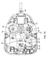
- FIG. 16B is a diagrammatic perspective cross-sectional view of another port feature.
- FIGS. 17A and 17B are diagrammatic views of yet another port feature.
- FIGS. 18A and 18B are diagrammatic views of yet another port feature.
- FIG. 19A is a perspective view of a cannula insertion/stabilizing fixture.
- FIG. 19B is another perspective view of a cannula insertion/stabilizing fixture.
- FIG. 19C is a diagrammatic perspective view of a cannula stabilizing fixture.
- FIGS. 20A-20D are diagrammatic views that illustrate another way of inserting cannulas.
- FIG. 21 is a diagrammatic view of a curved cannula and various reference axes.
- FIG. 22 is a diagrammatic view of a curved cannula and the distal end of a flexible instrument with associated optical fiber strain sensors.
- FIG. 23 is a diagrammatic view of a control system architecture.
- spatially relative terms such as “beneath”, “below”, “lower”, “above”, “upper”, “proximal”, “distal”, and the like—may be used to describe one element's or feature's relationship to another element or feature as illustrated in the figures.
- These spatially relative terms are intended to encompass different positions (i.e., locations) and orientations (i.e., rotational placements) of a device in use or operation in addition to the position and orientation shown in the figures. For example, if a device in the figures is turned over, elements described as “below” or “beneath” other elements or features would then be “above” or “over” the other elements or features.
- the exemplary term “below” can encompass both positions and orientations of above and below.
- a device may be otherwise oriented (rotated 90 degrees or at other orientations) and the spatially relative descriptors used herein interpreted accordingly.
- descriptions of movement along and around various axes includes various special device positions and orientations.
- the singular forms “a”, “an”, and “the” are intended to include the plural forms as well, unless the context indicates otherwise.
- the terms “comprises”, “comprising”, “includes”, and the like specify the presence of stated features, steps, operations, elements, and/or components but do not preclude the presence or addition of one or more other features, steps, operations, elements, components, and/or groups.
- Components described as coupled may be electrically or mechanically directly coupled, or they may be indirectly coupled via one or more intermediate components.
- flexible in association with a mechanical structure or component should be broadly construed. In essence, the term means the structure or component can be repeatedly bent and restored to an original shape without harm. Many “rigid” objects have a slight inherent resilient “bendiness” due to material properties, although such objects are not considered “flexible” as the term is used herein.
- a flexible mechanical structure may have infinite degrees of freedom (DOF's). Examples of such structures include closed, bendable tubes (made from, e.g., NITINOL, polymer, soft rubber, and the like), helical coil springs, etc. that can be bent into various simple and compound curves, often without significant cross-sectional deformation.
- each component is a short link in a kinematic chain, and movable mechanical constraints (e.g., pin hinge, cup and ball, live hinge, and the like) between each link may allow one (e.g., pitch) or two (e.g., pitch and yaw) DOF's of relative movement between the links.
- movable mechanical constraints e.g., pin hinge, cup and ball, live hinge, and the like
- a short, flexible structure may serve as, and be modeled as, a single mechanical constraint (joint) that provides one or more DOF's between two links in a kinematic chain, even though the flexible structure itself may be a kinematic chain made of several coupled links.
- joint a single mechanical constraint that provides one or more DOF's between two links in a kinematic chain, even though the flexible structure itself may be a kinematic chain made of several coupled links.
- a flexible mechanical structure or component may be either actively or passively flexible.
- An actively flexible piece may be bent by using forces inherently associated with the piece itself.
- one or more tendons may be routed lengthwise along the piece and offset from the piece's longitudinal axis, so that tension on the one or more tendons causes the piece to bend.
- Other ways of actively bending an actively flexible piece include, without limitation, the use of pneumatic or hydraulic power, gears, electroactive polymer, and the like.
- a passively flexible piece is bent by using a force external to the piece.
- An example of a passively flexible piece with inherent stiffness is a plastic rod or a resilient rubber tube.
- An actively flexible piece when not actuated by its inherently associated forces, may be passively flexible.
- a single component may be made of one or more actively and passively flexible portions in series.
- da Vinci® Surgical System specifically, a Model IS3000, marketed as the da Vinci® SiTM HDTM Surgical System
- Intuitive Surgical, Inc. of Sunnyvale, Calif.
- inventive aspects disclosed herein may be embodied and implemented in various ways, including robotic and non-robotic embodiments and implementations.
- Implementations on da Vinci® Surgical Systems e.g., the Model IS3000; the Model IS2000, marketed as the da Vinci® STM HDTM Surgical System
- da Vinci® STM HDTM Surgical System are merely exemplary and are not to be considered as limiting the scope of the inventive aspects disclosed herein.
- FIGS. 1A, 1B, and 1C are front elevation views of three main components of a teleoperated robotic surgical system for minimally invasive surgery. These three components are interconnected so as to allow a surgeon, with the assistance of a surgical team, perform diagnostic and corrective surgical procedures on a patient.
- FIG. 1A is a front elevation view of the patient side cart component 100 of the da Vinci® Surgical System.
- the patient side cart includes a base 102 that rests on the floor, a support tower 104 that is mounted on the base 102 , and several arms that support surgical tools (which include a stereoscopic endoscope).
- arms 106 a , 106 b are instrument arms that support and move the surgical instruments used to manipulate tissue
- arm 108 is a camera arm that supports and moves the endoscope.
- FIG. 1A also shows an optional third instrument arm 106 c that is supported on the back side of support tower 104 and that can be positioned to either the left or right side of the patient side cart as necessary to conduct a surgical procedure.
- FIG. 1A also shows an optional third instrument arm 106 c that is supported on the back side of support tower 104 and that can be positioned to either the left or right side of the patient side cart as necessary to conduct a surgical procedure.
- 1A further shows interchangeable surgical instruments 110 a , 110 b , 110 c mounted on the instrument arms 106 a , 106 b , 106 c , and it shows endoscope 112 mounted on the camera arm 108 .
- the arms are discussed in more detail below. Knowledgeable persons will appreciate that the arms that support the instruments and the camera may also be supported by a base platform (fixed or moveable) mounted to a ceiling or wall, or in some instances to another piece of equipment in the operating room (e.g., the operating table). Likewise, they will appreciate that two or more separate bases may be used (e.g., one base supporting each arm).
- FIG. 1B is a front elevation view of a surgeon's console 120 component of the da Vinci® Surgical System.
- the surgeon's console is equipped with left and right multiple DOF master tool manipulators (MTM's) 122 a , 122 b , which are kinematic chains that are used to control the surgical tools (which include the endoscope and various cannulas).
- the surgeon grasps a pincher assembly 124 a , 124 b on each MTM 122 , typically with the thumb and forefinger, and can move the pincher assembly to various positions and orientations.
- each MTM 122 is coupled to control a corresponding instrument arm 106 for the patient side cart 100 .
- left MTM 122 a may be coupled to control instrument arm 106 b and instrument 110 a
- right MTM 122 b may be coupled to control instrument arm 106 b and instrument 110 b
- left MTM 122 a can be switched between controlling arm 106 a and instrument 110 a to controlling arm 106 c and instrument 110 c
- right MTM 122 a can be switched between controlling arm 106 b and instrument 110 b to controlling arm 106 c and instrument 110 c .
- control assignments between MTM's 122 a , 122 b and arm 106 a /instrument 110 a combination and arm 106 b /instrument 110 b combination may also be exchanged. This may be done, for example, if the endoscope is rolled 180 degrees, so that the instrument moving in the endoscope's field of view appears to be on the same side as the MTM the surgeon is moving.
- the pincher assembly is typically used to operate a jawed surgical end effector (e.g., scissors, grasping retractor, needle driver, and the like) at the distal end of an instrument 110 .
- Surgeon's console 120 also includes a stereoscopic image display system 126 .
- Left side and right side images captured by the stereoscopic endoscope 112 are output on corresponding left and right displays, which the surgeon perceives as a three-dimensional image on display system 126 .
- the MTM's 122 are positioned below display system 126 so that the images of the surgical tools shown in the display appear to be co-located with the surgeon's hands below the display. This feature allows the surgeon to intuitively control the various surgical tools in the three-dimensional display as if watching the hands directly. Accordingly, the MTM servo control of the associated instrument arm and instrument is based on the endoscopic image reference frame.
- the endoscopic image reference frame is also used if the MTM's are switched to a camera control mode.
- the surgeon may move the distal end of the endoscope by moving one or both of the MTM's together (portions of the two MTM's may be servomechanically coupled so that the two MTM portions appear to move together as a unit).
- the surgeon may then intuitively move (e.g., pan, tilt, zoom) the displayed stereoscopic image by moving the MTM's as if holding the image in the hands.
- the surgeon's console 120 is typically located in the same operating room as the patient side cart 100 , although it is positioned so that the surgeon operating the console is outside the sterile field.
- One or more assistants typically assist the surgeon by working within the sterile surgical field (e.g., to change tools on the patient side cart, to perform manual retraction, etc.). Accordingly, the surgeon operates remote from the sterile field, and so the console may be located in a separate room or building from the operating room.
- two consoles 120 may be networked together so that two surgeons can simultaneously view and control tools at the surgical site.
- FIG. 1C is a front elevation view of a vision cart component 140 of the da Vinci® Surgical System.
- the vision cart 140 houses the surgical system's central electronic data processing unit 142 and vision equipment 144 .
- the central electronic data processing unit includes much of the data processing used to operate the surgical system. In various other implementations, however, the electronic data processing may be distributed in the surgeon console and patient side cart.
- the vision equipment includes camera control units for the left and right image capture functions of the stereoscopic endoscope 112 .
- the vision equipment also includes illumination equipment (e.g., Xenon lamp) that provides illumination for imaging the surgical site.
- the vision cart includes an optional 24-inch touch screen monitor 146 , which may be mounted elsewhere, such as on the patient side cart 100 .
- the vision cart 140 further includes space 148 for optional auxiliary surgical equipment, such as electrosurgical units and insufflators.
- auxiliary surgical equipment such as electrosurgical units and insufflators.
- the patient side cart and the surgeon's console are coupled via optical fiber communications links to the vision cart so that the three components together act as a single teleoperated minimally invasive surgical system that provides an intuitive telepresence for the surgeon.
- a second surgeon's console may be included so that a second surgeon can, e.g., proctor the first surgeon's work.
- FIG. 2A is a side elevation view of an illustrative instrument arm 106 .
- the arm is made of a series of links and joints that couple the links together.
- the arm is divided into two portions. The first portion is the “set-up” portion 202 , in which unpowered joints couple the links.
- the second portion is powered, robotic manipulator portion 204 (patient side manipulator; “PSM”) that supports and moves the surgical instrument.
- PSM patient side manipulator
- the set-up portion 202 is moved to place the manipulator portion 204 in the proper position to carry out the desired surgical task.
- the set-up portion joints are then locked (e.g., with brake mechanisms) to prevent this portion of the arm from moving.
- FIG. 2B is a perspective view of the PSM 204 with an illustrative instrument 110 mounted.
- the PSM 204 includes a yaw servo actuator 206 , a pitch servo actuator 208 , and an insertion and withdrawal (“I/O”) actuator 210 .
- An illustrative surgical instrument 110 is shown mounted at an instrument mounting carriage 212 .
- An illustrative straight cannula 214 is shown mounted to cannula mount 216 .
- Shaft 218 of instrument 110 extends through cannula 214 .
- PSM 204 is mechanically constrained so that it moves instrument 110 around a stationary remote center of motion 220 located along the instrument shaft.
- Yaw actuator 206 provides yaw motion 222 around remote center 220
- pitch actuator 208 provides pitch motion 224 around remote center 220
- I/O actuator 210 provides insertion and withdrawal motion 226 through remote center 220 .
- the set up portion 202 is typically positioned to place remote center of motion 220 at the incision in the patient's body wall during surgery and to allow for sufficient yaw and pitch motion to be available to carry out the intended surgical task.
- Knowledgeable persons will understand that motion around a remote center of motion may also be constrained solely by the use of software, rather than by a physical constraint defined by a mechanical assembly.
- Matching force transmission disks in mounting carriage 212 and instrument force transmission assembly 230 couple actuation forces from actuators 232 in PSM 204 to move various parts of instrument 110 in order to position, orient, and operate instrument end effector 234 .
- Such actuation forces may typically roll instrument shaft 218 (thus providing another DOF through the remote center), operate a wrist 236 that provides yaw and pitch DOF's, and operate a movable piece or grasping jaws of various end effectors (e.g., scissors (cautery or non-cautery capable), dissectors, graspers, needle drivers, electrocautery hooks, retractors, clip appliers, etc.).
- FIG. 2C is a side elevation view of a portion of a camera arm 108 with an illustrative camera 112 mounted. Similar to the instrument arm 106 , the camera arm 108 includes a set-up portion 240 and a manipulator portion 242 (endoscopic camera manipulator; “ECM”). ECM 242 is configured similarly to PSM 204 and includes a yaw motion actuator 244 , a pitch motion actuator 246 , and an I/O motion actuator 248 . Endoscope 112 is mounted on carriage assembly 250 , and endoscope cannula 252 is mounted on camera cannula mount 254 . ECM 242 moves endoscope 112 around and through remote center of motion 256 .
- ECM endoscopic camera manipulator
- incisions are made into the patient's body (usually with the use of a trocar to place the associated cannula).
- One incision is for the endoscope camera instrument, and the other incisions are for the necessary surgical instruments.
- Such incisions are sometimes referred to as “ports”, a term which may also mean a piece of equipment that is used within such an incision, as described in detail below.
- several instrument and/or camera ports are necessary in order to provide the needed access and imaging for a surgical site.
- the incisions are relatively small in comparison to larger incisions used for traditional open surgery, there is the need and desire to further reduce the number of incisions to further reduce patient trauma and for improved cosmesis.
- Single port surgery is a technique in which all instruments used for minimally invasive surgery are passed through a single incision in the patient's body wall, or in some instances through a single natural orifice.
- Such methods may be referred to by various terms, such as Single Port Access (SPA), Laparo Endoscopic Single-site Surgery (LESS), Single Incision Laparoscopic Surgery (SILS), One Port Umbilical Surgery (OPUS), Single Port Incisionless Conventional Equipment-utilizing Surgery (SPICES), Single Access Site Surgical Endoscope (SASSE), or Natural Orifice TransUmbilical Surgery (NOTUS).
- SPA Single Port Access
- LESS Laparo Endoscopic Single-site Surgery
- SIFS Single Incision Laparoscopic Surgery
- OPUS One Port Umbilical Surgery
- SPICES Single Port Incisionless Conventional Equipment-utilizing Surgery
- SASSE Single Access Site Surgical Endoscope
- NOTES Natural Orifice TransUmbilical Surgery
- the use of a single port may done using either manual instruments or a robotic surgical system, such
- Two instruments, for example, are positioned nearly side-by-side, and so it is difficult to achieve advantageous triangulation angles at the surgical site (triangulation being the ability for the distal ends of two surgical instruments to be positioned along two legs of a triangle to work effectively at a surgical site at the apex of the triangle).
- triangulation being the ability for the distal ends of two surgical instruments to be positioned along two legs of a triangle to work effectively at a surgical site at the apex of the triangle).
- straight instrument shafts tend to obscure a large part of the endoscope's field of view.
- the multiple manipulators may interfere with one another, due to both their size and their motions, which also limits the amount of end effector movement available to the surgeon.
- FIG. 3 illustrates the difficulty of using a multi-arm robotic surgical system for single port surgery.
- FIG. 3 is a diagrammatic view of multiple cannulas and associated instruments inserted through a body wall so as to reach a surgical site 300 .
- a camera cannula 302 extends through a camera incision 304
- a first instrument cannula 306 extends through a first instrument incision 308
- a second instrument cannula 310 extends through a second instrument incision 312 .
- FIG. 4A is a schematic view of a portion of a patient side robotic manipulator that supports and moves a combination of a curved cannula and a passively flexible surgical instrument.
- a telerobotically operated surgical instrument 402 a includes a force transmission mechanism 404 a , a passively flexible shaft 406 a , and an end effector 408 a .
- Instrument 402 a is mounted on an instrument carriage assembly 212 a of a PSM 204 a (previously described components are schematically depicted for clarity).
- Interface discs 414 a couple actuation forces from servo actuators in PSM 204 a to move instrument 402 a components.
- End effector 408 a illustratively operates with a single DOF (e.g., closing jaws).
- a wrist to provide one or more end effector DOF's e.g., pitch, yaw; see e.g., U.S. Pat. No. 6,817,974 (filed Jun. 28, 2002) (disclosing “Surgical Tool Having Positively Positionable Tendon-Actuated Multi-Disk Wrist Joint”), which is incorporated herein by reference) is optional and is not shown. Many instrument implementations do not include such a wrist.
- FIG. 4A further shows a curved cannula 416 a , which has a proximal end 418 a , a distal end 420 a , and a central channel 422 a that extends between proximal end 418 a and distal end 420 a .
- Curved cannula 416 a is, in one implementation, a rigid, single piece cannula.
- proximal end 418 a of curved cannula 416 a is mounted on PSM 204 a 's cannula mount 216 a .
- instrument 402 a 's flexible shaft 406 a extends through curved cannula 416 a 's central channel 422 a so that a distal portion of flexible shaft 406 a and end effector 408 a extend beyond cannula 416 a 's distal end 420 a in order to reach surgical site 424 .
- PSM 204 a As described above, PSM 204 a 's mechanical constraints (or, alternately, preprogrammed software constraints in the control system for PSM 204 a ) cause instrument 402 a and curved cannula 416 a to move in pitch and yaw around remote center of motion 426 located along cannula 416 a , which is typically placed at an incision in the patient's body wall. PSM 204 a 's I/O actuation, provided by carriage 212 a , inserts and withdraws instrument 402 a through cannula 416 a to move end effector 408 a in and out. Details of instrument 402 a , cannula 416 a , and the control of these two components is described below.
- FIG. 4B is a schematic view that shows a second patient side robotic manipulator that supports and moves a second curved cannula and passively flexible surgical instrument combination, added to the FIG. 4A view.
- Components of the second PSM 204 b , instrument 402 b , and curved cannula 416 b are substantially similar to, and function in a substantially similar manner to, those described in FIG. 4A .
- Curved cannula 416 b curves in a direction opposite to the direction in which curved cannula 416 a curves.
- FIG. 4B is a schematic view that shows a second patient side robotic manipulator that supports and moves a second curved cannula and passively flexible surgical instrument combination, added to the FIG. 4A view.
- Components of the second PSM 204 b , instrument 402 b , and curved cannula 416 b are substantially similar to, and function in a substantially similar manner to, those described in FIG. 4A .
- FIG. 4B thus illustrates that two curved cannulas and associated instruments, curving in opposite directions, are positioned to extend through a single incision 428 in the patient's body wall 430 to reach surgical site 424 .
- Each curved cannula initially angles away from a straight line between the incision and the surgical site and then curves back towards the line to direct the extended instruments to the surgical site.
- the distal ends 420 a , 420 b of the curved cannulas move accordingly, and therefore instrument end effectors 404 a and 404 b are moved with reference to the surgical site (and consequently, with reference to the endoscope's field of view). It can be seen that although the remote centers of motion for the two curved cannula and flexible instrument combinations are not identical, they are sufficiently close enough (proximate) to one another so that they can both be positioned at the single incision 428 .
- FIG. 4C is a schematic view that shows an endoscopic camera manipulator that supports an endoscope, added to the FIG. 4B view. Some previously used reference numbers are omitted for clarity.
- ECM 242 holds endoscope 112 such that it extends through single incision 428 , along with the two curved cannula and flexible instrument combinations. Endoscope 112 extends through a conventional cannula 252 supported by cannula mount 254 . In some implementations, cannula 252 provides insufflation to a body cavity. ECM 242 is positioned to place the endoscope 112 's remote center of motion at incision 428 .
- the remote centers of motion for the two curved cannula and instrument combinations and the endoscope 112 are not identical, but they may be positioned sufficiently close to allow all to extend through the single incision 428 without the incision being made unduly large.
- the three remote centers may be positioned on approximately a straight line, as illustrated in FIG. 4C .
- the remote centers are not linearly aligned, yet are grouped sufficiently close.
- FIG. 4C also schematically illustrates that the PSM's 204 a , 204 b and the ECM 242 may be positioned so that each has a significantly improved volume in which to move in pitch and yaw without interfering with each other. That is, if straight-shaft instruments are used, then the PSM's must in general remain in positions near one another to keep the shafts in a near parallel relation for effective work through a single incision. But with the curved cannulas, however, the PSM's can be placed farther from one another, and so each PSM can in general move within a relatively larger volume than with the straight-shaft instruments.
- FIG. 4C illustrates how the curved cannulas 416 provide an improved triangulation for the surgical instruments, so that the surgical site 426 is relatively unobstructed in endoscope 112 's field of view 430 .
- FIG. 4C further illustrates that a port feature 432 may be placed in incision 428 .
- Cannulas 416 a , 416 b , and 252 each extend through port feature 432 .
- Such a port feature may have various configurations, as described in detail below.
- FIG. 5 is a diagrammatic view of an illustrative flexible instrument 500 used with a curved cannula.
- Instrument 500 includes a proximal end force transmission mechanism 502 , a distal end surgical end effector 504 , and a shaft 506 that couples force transmission mechanism 502 and end effector 504 .
- shaft 506 is about 43 cm long.
- shaft 506 is passively flexible and includes three sections—a proximal section 506 a , a distal section 506 c , and a middle section 506 b that is between proximal and distal sections 506 a , 506 c.
- the sections 506 a , 506 b , 506 c may be each characterized by their different stiffnesses.
- Section 506 a is the portion of shaft 506 that extends from force transmission mechanism 502 towards the curved cannula through which the other sections of shaft 506 extend. Consequently, section 506 a is relatively stiff in comparison to the other sections 506 b , 506 c .
- section 506 a may be effectively rigid.
- Section 506 b is relatively more flexible than the other two sections 506 a , 506 c .
- section 506 b is within the curved cannula during a surgical procedure, and so section 506 b is made relatively flexible to reduce friction with the inner wall of the curved cannula, yet it is not made so flexible so that it buckles during insertion under manual or servocontrolled operation.
- Section 506 c is relatively more stiff than section 506 b , because section 506 c extends from the distal end of the curved cannula. Accordingly, section 506 c is made flexible enough so that it may be inserted through the bend of the curved cannula, yet it is made rigid enough to provide adequate cantilever support for end effector 504 .
- shaft sections 506 a - 506 c each have the same physical structure—each being composed of the same material(s), and the material(s) chosen to have a bending stiffness acceptable for each section—so the sections thus have the same stiffness.
- Such instrument shafts are generally lower cost because, e.g., they have fewer parts and are easier to assemble.
- all three sections 506 a - 506 c are torsionally rigid enough to transmit roll motion from the proximal end of the instrument to distal surgical end effector 504 . Examples are described in reference to FIGS. 8A-8D , below.
- the stiffness of the instrument shaft (or at least the portion of the shaft that moves within the cannula), with an outer material selected to reasonably minimize shaft friction within the cannula, is close to the maximum that the robot can insert and roll.
- Such insertion and roll forces are substantially more than forces that can be reasonably controlled by a human, and so the stiffness of the instrument's distal section that extends from the distal end of the cannula can be made substantially higher than hand-operated instrument shaft stiffness would be for a similar but manually actuated curved cannula system.
- the instrument shaft is “tuned” (e.g., by selecting one or more particular materials and/or by various shaft constructions using the selected material(s)) to (i) make effective use of the robot's insertion and roll drive capabilities with reasonably stiff shafts while (ii) not allowing the friction between such reasonably stiff shafts and a particular cannula curve dimension to offset the robot's drive capability benefits.
- certain instruments may have flexible shafts of one stiffness for use with cannulas with one curve radius and/or inner diameter
- other instruments may have shafts of another stiffness for use with cannulas with another curve radius and/or inner diameter.
- shaft stiffness for an instrument designed for use with a cannula having a relatively larger curve radius may be larger than shaft stiffness for an instrument designed for use with a cannula having a relatively smaller curve radius.
- the shaft's lateral (bending) stiffness is in a range from about 1 lb-in 2 (PSI ⁇ in 4 ) to about 4 lb-in 2 , and in one implementation the shaft's lateral stiffness is about 2.0 lb-in 2 .
- the shaft's rotational stiffness is larger than about 11 lb-in 2 , and in one implementation the shaft's rotational stiffness is about 22.0 lb-in 2 .
- a practical range of rotational stiffness is in the range of about 11 lb-in 2 to about 66 lb-in 2 .
- instrument shaft stiffness must also decrease. If an isotropic material is used for the instrument shaft, such as is illustrated in association with FIGS. 8C and 8D , then the stiffness of the shaft portion that extends from the cannula's distal end is also reduced. At some point, either the stiffness of the shaft's extended distal end or the stiffness of the shaft portion between the transmission mechanism and the cannula may become unacceptably low. Therefore, as described above, a range of stiffnesses may be defined for an isotropic material shaft of fixed dimensions, depending on a cannula's bend radius and inner diameter.
- Surgical instrument end effectors placed at the distal end of the flexible shaft instruments are of two general types.
- the first type of end effector has no moving parts.
- Such non-moving end effectors may include, for example, suction/irrigation tips, electrocautery hooks or blades, probes, blunt dissectors, cameras, retractors, etc.
- the second type of end effector has at least one moving component that is actuated under robotic control.
- Such moving component end effectors include, for example, graspers, needle drivers, moving cautery hooks, clip appliers, shears (both non-cautery and cautery), etc.
- the one or more moving end effector components may be actuated in various ways.
- two tension elements may be used to actuate an end effector component.
- one tension element moves the end effector component in one direction
- the second tension element moves the component in the opposite direction.
- a single compression/tension element is used to move the end effector component.
- pulling (tension) is used to move the component in one direction
- pushing (compression) is used to move the component in the opposite direction.
- the tension force is used to actuate the end effector component in the direction that requires the highest force (e.g., closing jaws).
- FIG. 6A is a diagrammatic view that illustrates aspects of a pull/pull instrument design.
- an instrument force transmission mechanism 602 is coupled to a grip-type end effector 604 by a flexible shaft body 606 .
- a tension element 608 is routed through shaft body 606 and couples a movable component in end effector 604 to a component (not shown; see below) in transmission mechanism 602 that receives a robotic actuation force.
- Tension element 608 is routed through a force isolation component 610 that is coupled between the base 612 of the end effector and backing plate 614 in transmission mechanism 602 .
- shaft body 606 is a plastic tube (e.g., polyaryletheretherketone (PEEK)), tension element 608 is a hypotube (e.g., 316 Stainless Steel (face hardened), 0.028-inch OD ⁇ 0.020 ID, with polytetrafluoroethylene (PTFE) dip coating) with cables (e.g., 0.018-inch tungsten) at each end that are coupled to the transmission mechanism and end effector components, and force isolation component 610 is a coil tube (e.g., 300 series stainless steel).
- PEEK polyaryletheretherketone
- shaft body 606 does not experience the tension load on tension element 608 that moves the end effector component, because the tension force is offset by an equal and opposite reaction force in isolation component 610 . Consequently, two such tension element and force isolation component pairs within shaft body tube 606 can be used for a pull/pull end effector actuation design, the instrument shaft remains flexible with no effective change in its designed stiffness or bend during pull/pull actuation, and the tension load on tension element 608 is effectively independent of shaft body 606 bending.
- 304V vacuum arc remelt
- FIG. 6B is a diagrammatic view that illustrates aspects of a push/pull instrument design.
- an instrument force transmission mechanism 620 is coupled to a grip-type end effector 622 by a flexible shaft body 624 .
- a compression/tension drive element 626 is routed through shaft body 624 and couples a movable component in end effector 622 to a component (not shown; see below) in transmission mechanism 620 that receives a robotic actuation force.
- One or more force isolation components 628 are also routed through shaft body 624 and are coupled to the base 630 of the end effector and to a backing plate 632 in the force transmission mechanism.
- shaft body 624 is a plastic tube (e.g., PEEK), drive element 626 is a solid rod (e.g., 304V Stainless Steel, 0.032-inch OD with PTFE spray coating), and force isolation components 628 are also solid rods (e.g., 304V Stainless Steel, 0.032-inch OD with PTFE spray coating). It can be seen that shaft body 624 does not experience either the compression or tension loads on drive element 626 that moves the end effector component, because the drive forces are offset by equal and opposite reaction forces in isolation components 628 .
- PEEK plastic tube
- drive element 626 is a solid rod (e.g., 304V Stainless Steel, 0.032-inch OD with PTFE spray coating)
- force isolation components 628 are also solid rods (e.g., 304V Stainless Steel, 0.032-inch OD with PTFE spray coating). It can be seen that shaft body 624 does not experience either the compression or tension loads on drive element 626 that moves the end
- the instrument shaft remains flexible with no effective change in its designed stiffness or bend during push/pull actuation, and the drive loads on drive element 626 are effectively independent of shaft body 624 bending.
- the force isolation components 628 can act to effectively increase the instrument shaft's bending stiffness a desired value.
- FIG. 7A is a bottom view of an implementation of force transmission mechanism 502 .
- the force transmission mechanism of a surgical instrument used in a da Vinci® Surgical System has been modified to eliminate the mechanisms used to control a wrist mechanism on the instrument and to control the jaw of an end effector (or other moveable part) using only a single interface disk.
- one interface disk 702 a rolls shaft 506 so as to provide a roll DOF for end effector 504
- a second interface disk 702 b operates end effector 504 's jaw mechanism.
- a bulkhead in transmission mechanism 502 supports coil tubes that run through the instrument shaft, as described in detail above and below.
- Force transmission mechanism 502 may be coupled to PSM 204 without any mechanical modifications required to the PSM, a feature that minimizes implementation costs of curved cannula aspects in existing robotic surgical systems.
- FIG. 7A also shows that implementations of force transmission mechanism 502 may include electrically conductive interface pins 704 and an electronic data memory 706 that is electrically coupled to interface pins 704 .
- Parameters relevant to instrument 500 and its operation e.g., number of times the instrument has been used, Denavit-Hartenberg parameters for control (described below), etc.
- Parameters relevant to instrument 500 and its operation may be stored in memory 706 and accessed by the robotic surgical system during operation to properly use the instrument (see e.g., U.S. Pat. No. 6,331,181 (filed Oct. 15, 1999)(disclosing surgical robotic tools, data architecture, and use), which is incorporated herein by reference).
- kinematic data specific to the curved cannula through which the instrument extends may also be stored in memory 706 , so that if the system detects that a curved cannula is mounted (see e.g., FIG. 10 and associated text below), the system may access and use the stored cannula data. If more than one curved cannula kinematic configuration (e.g., different lengths, bend radii, bend angles, etc.) is used, then data specific to each allowable configuration may be stored in the associated instrument's memory, and the system may access and use data for the specific cannula configuration that is mounted. In addition, in some instances if the robotic surgical system senses that a flexible instrument has been coupled to a manipulator that holds a straight, rather than curved, cannula, then the system may declare this situation to be an illegal state and prevent operation.
- a curved cannula kinematic configuration e.g., different lengths, bend radii, bend angles, etc.
- FIG. 7B is a plan view of an illustrative implementation of a force transmission mechanism used in a pull/pull instrument design. As shown in FIG. 7B , two coil tubes 730 are positioned against backing plate 732 . Two tension elements 734 extend from the coil tubes, through the backing plate, and are routed to open/close capstan 736 , which rotates as indicated by arrows 738 to pull on one or the other of the tension elements.
- FIG. 7B also depicts an illustrative implementation of shaft roll—cross-connected helical drive gear 740 and shaft roll gear 742 . Roll gear 742 is coupled (e.g., laser welded) to a stainless steel adaptor swaged over the proximal end of the flexible shaft's body tube.
- FIG. 7B is a plan view of an illustrative implementation of a force transmission mechanism used in a pull/pull instrument design. As shown in FIG. 7B , two coil tubes 730 are positioned against backing plate 732 . Two tension
- FIG. 7B further depicts an illustrative monopolar electrocautery energy connection 744 between plug 746 and electrically conductive tension elements 734 .
- FIG. 7B depicts an illustrative positioning of a memory chip 748 that contains instrument and/or associated cannula data, as described herein, and the chip's associated electrical contacts 750 that connect with the surgical system through mating contacts on the PSM.
- FIG. 7C is a plan view of an illustrative implementation of a force transmission mechanism used in a push/pull instrument design.
- force isolation rods 760 extend out of the proximal end of the flexible instrument shaft and are joined with backing plate 762 .
- Push/pull drive element rod 764 also extends out of the proximal end of the instrument shaft, and further extends through backing plate 762 to be coupled with slider 766 .
- drive element rod 764 is coupled with linear slider 766 using a free rolling bearing 768 . This free rolling bearing prevents the drive rod from twisting when the instrument shaft is rolled (i.e., provides an unconstrained roll DOF).
- Push/pull drive gear 770 is engaged with lever gear 772 .
- Lever gear 772 is coupled to slider 766 with link (offset crank) 774 .
- link (offset crank) 774 As drive gear 770 turns back and forth as indicated by arrows 776 , slider 766 slides along shaft 778 as indicated by arrows 780 , thus moving drive element 764 along the instrument shaft's longitudinal axis.
- FIG. 7C shaft roll implementation is substantially similar to the implementation described above with reference to FIG. 7B .
- FIG. 7C also shows an illustrative flush fluid entry port 790 at the proximal end of the instrument shaft.
- the flush fluid port is made part of the assembly that couples the shaft body tube to the roll gear.
- Flush fluid may be directed into the port to clean components inside the shaft. For example, even though an actuating drive rod or cable may extend through a wipe seal at the distal end of the shaft, a small amount of body fluid may pass the seal and enter the inside of the shaft body.
- FIG. 7D is a perspective view of another illustrative implementation of a force transmission mechanism used in a push/pull instrument design.
- two pinion drive gears 782 engage a rack gear 784 between them.
- the rack is round, and a flat rack may be used instead.
- the push/pull drive element rod is coupled to the rack (e.g., with a free rolling bearing as described above).
- the implementation depicted in FIG. 7D uses two extra drive elements and associated interface disks (not shown; see e.g., FIG. 7A ) positioned towards the rear of the force transmission mechanism, and the drive elements rotate in opposite directions to move the rack along the instrument shaft's longitudinal axis.
- This implementation design uses fewer parts, and so is less expensive and simpler to manufacture than the implementation shown in FIG. 7C , although this FIG. 7D implementation does use an extra drive element in the force transmission mechanism's interface to the robotic manipulator.
- An advantage of using more than one drive element, however, is that the mechanism can exert more force in comparison to using only a single, comparable drive element (e.g., effectively two times as much if two drive elements are used).
- FIG. 8A is a cutaway perspective view that shows an illustrative structure of a portion of instrument shaft 506 .
- Two tension elements 802 a , 802 b extend through a distal portion of shaft 506 and are coupled to operate the end effector (shown diagrammatically; e.g., a 5 mm diameter class surgical end effector used in da Vinci® Surgical System instruments).
- Tension elements 802 a , 802 b may be separate, or they may be parts of the same element that, for example, wraps around a pulley in the end effector.
- tension elements 802 a , 802 b are 0.018-inch tungsten wire. As shown in FIG.
- proximal ends of tension elements 802 a , 802 b are coupled (e.g., crimped, etc.) to distal ends of second tension elements 804 a , 804 b that further extend proximally through most of shaft 506 .
- tension elements 804 a , 804 b are 0.032-inch stainless steel hypotubes.
- tension elements 804 a , 804 b are coupled to transmission mechanism 502 using wires coupled in a similar manner, as described above.
- tension elements 804 a , 804 b extend through support tubes 806 a , 806 b respectively, which guide tension elements 804 a , 804 b and keep them from buckling or kinking within shaft 506 .
- support tubes 806 a , 806 b are stainless steel (e.g., 304V (vacuum melt that reduces friction)) coil tubes (0.035-inch inner diameter; 0.065-inch outer diameter), and other materials and structures may be used.
- a friction reducing sheath 808 a , 808 b is placed between the tension element and the inner wall of the support tube.
- sheaths 808 a , 808 b are PTFE, and other materials may be used. Both support tubes 806 a , 806 b are placed within a single inner shaft tube 810 .
- a flat-spiral stainless steel wire is used for inner shaft tube 810 to provide torsional stiffness during roll.
- An outer shaft tube 812 e.g., braided stainless steel mesh or other material suitable to protect the shaft components
- An elastomer skin 814 e.g., Pellothane®, or other suitable material surrounds the outer shaft tube 812 .
- Skin 814 protects the inner components of shaft 506 from direct contamination by, e.g., body fluids during surgery, and the skin facilitates shaft 506 sliding within the curved cannula.
- shaft 506 is approximately 5.5 mm (0.220 inches) outer diameter.
- the support tube and tension element assemblies may be dip coated in PTFE to provide a “sheath” that reduces friction.
- the space between the coils is filled in by the dip coating material to form a tube.
- wire is pre-coated before the coil is wound, and the coil is then baked to remelt the coating and form the solid tube.
- the ends of the tube may be sealed around the tension elements to prevent contamination (e.g., body fluids) from entering between the tension element and the coil tube.
- Shaft 506 may include additional components.
- one or more stiffening rods 816 run through various portions of shaft 506 .
- the number, size, and composition of rods 816 may be varied to provide the various stiffnesses of portions 506 a - 506 c , as described above.
- rods 816 are stainless steel.
- one or more additional rods 818 of another material may run through one or more portions of shaft 506 .
- FIG. 8A shows a second rod of PEEK that in one implementation runs through distal section 506 c to provide stiffness in addition to the stiffness from rods 516 .
- one or more supplemental tubes to provide, e.g., suction and/or irrigation or flushing for cleaning may be included in shaft 506 , either in addition to or in place of the stiffening rods.
- additional tension elements may be included to operate, e.g., an optional multi-DOF wrist mechanism at the distal end of the instrument shaft.
- FIG. 8B is a cross-sectional diagrammatic perspective view of another implementation of an instrument shaft design.
- two hypotube tension elements 820 with PTFE coating are positioned within force isolation coil tubes 822 .
- An optional fluorinated ethylene propylene (FEP) insulation layer may surround the coil tubes.
- a PEEK body tube 824 surrounds the tension elements and coil tubes, and an FEP heat shrink skin 826 surrounds the body tube.
- An optional flush tube 828 may be placed inside body tube 824 , and it is configured so that cleaning fluid from the proximal end of the shaft travels through the cleaning tube to the distal end of the shaft, and then back through the body tube to flush out, e.g., contaminating body fluids.
- the instrument materials are selected, nevertheless, to allow the instrument to be autoclavable for sterilization.
- FIG. 8C is a cutaway perspective view that shows another illustrative structure of a portion of instrument shaft 506 .
- Tension elements 830 a , 830 b , 832 a , and 832 b are similar to tension elements 802 a , 802 b , 804 a , and 804 d described above.
- the tension elements are each routed through individual channels in multi-channel support tube 834 .
- tube 834 is a FEP extrusion with multiple channels 836 , and other materials may be used. FEP provides a low-friction surface against which the tension elements slide.
- stiffening rods may be routed through various other channels 836 in support tube 834 to provide desired stiffnesses for each of the instrument shaft sections 506 a - 506 c .
- a seven-channel tube 834 (six channels arranged around a central channel) is shown in FIG. 8C , and a stiffening rod or other element may be inserted into the center channel.
- Additional cables e.g., to operate an optional multi-DOF wrist mechanism at the distal end of shaft 506 , may be routed through other channels in tube 834 .
- other functions such as suction and/or irrigation, may be provided through the channels.
- FIG. 8C further shows a shaft body tube 838 (e.g., extruded PEEK or other suitable material) surrounding support tube 834 to provide axial and torsional stiffness to shaft 506 .
- An outer skin or coating 840 surrounds body tube 838 to reduce friction as shaft 506 slides inside the curved cannula and to protect the shaft components.
- skin 840 is a 0.005-inch layer of FEP that is heat shrunk around body tube 838 , and other suitable materials may be used.
- the shaft 506 outer diameter is approximately 5.5 mm (0.220 inches), with a single extrusion PEEK body tube having an outer diameter of approximately 5.0 mm and an inner diameter of about 3.5 mm.
- PEEK is used because its stiffness (modulus of elasticity, or Young's modulus) is low enough to allow bending with low enough radial force to limit friction inside the curved cannula so that instrument I/O is not affected in a meaningful way, but its modulus of elasticity is high enough to provide good cantilever beam stiffness for the shaft distal portion 506 c that extends beyond the distal end of the curved cannula, to resist buckling of any portion of the shaft between the transmission mechanism and the proximal end of the cannula, and to transmit roll motion and torque along the length of the instrument shaft with adequate stiffness and precision.
- FIG. 8D is a diagrammatic transparent perspective view that shows yet another implementation a flexible instrument shaft design.
- a push/pull drive element 850 extends through a center channel 852 in a multi-channel tube 854 , which is similar to tube 834 described above.
- Three force isolation/stiffening rods 856 as described above extend through three of the channels 858 surrounding the center channel.
- the distal ends of the rods 856 include stainless steel plugs that fit into the channels.
- the remaining three channels 860 surrounding the center channel are left open and are used as flush fluid channels. In other implementations, however, other elements may be routed through one or more of the channels 860 .
- the surrounding instrument shaft body tube and skin are omitted from the drawing for clarity.
- FIG. 9A is an exploded perspective view of an implementation of the distal end of a flexible shaft instrument.
- two coil tubes 902 are coupled to distal end cap 904 .
- the coil tubes are positioned inside body tube 906 with outer skin 908 as described above (the tension elements are not shown).
- a tension element seal 910 is fitted into end cap 904 , and the tension elements extend through seal 910 , which keeps fluids from entering into the coil tubes.
- seal 910 is a molded silicone wipe seal.
- Adaptor cap 912 is positioned over the distal end of the body tube, and the end effector clevis 914 is coupled to the adaptor cap.
- FIG. 9B is a cross-sectional view of the implementation depicted in FIG. 9A .
- end cap 904 includes ridges 916 that enable the cap to be swaged inside body tube 906 .
- Coil tubes 902 are positioned against cap 904 , and tension element cables 918 are routed through cap 904 and seal 910 .
- Adaptor cap 912 is swaged over body tube 906 , and in the illustrative implementation is tapered to allow FEP heatshrink skin 908 to cover a portion of cap 912 .
- End effector clevis 914 is coupled (e.g., laser welded) to adaptor cap 912 .
- a single clevis and adapter cap piece may be substituted for the cap 912 and clevis 914 . The single piece reduces manufacturing cost and complexity by eliminating the laser weld.
- FIG. 9C is a diagrammatic view that illustrates a pull/pull type end effector that may be at the distal end of the flexible shaft instruments. As depicted in FIG. 9C , pulling on one cable opens the end effector jaws, and pulling on the other cable closes the end effector jaws.
- FIG. 9D is an exploded perspective view of another implementation of the distal end of a flexible shaft instrument.
- end cap 920 fits inside the distal end of shaft body tube 922 .
- Wipe seal 924 covers the opening in end cap 920
- push/pull drive rod connector 926 extends through end cap 920 and seal 924 to couple with the movable component of the end effector.
- End effector clevis and attachment cap assembly 928 fits over the end of shaft body tube 922 .
- the components are assembled in a manner similar to that described in relation to FIG. 9B (e.g., the use of swaging, etc.).
- the opening in seal 924 for the drive rod connector is slightly undersized, and compressing the seal before swaging assembly 928 to the shaft body tube further closes the seal around the drive rod connector.
- FIG. 9E is a diagrammatic view that illustrates a push/pull type end effector that may be at the distal end of the flexible shaft instruments (an illustrative clip applier end effector is shown). As depicted in FIG. 9E , pushing on the drive rod closes the end effector jaws, and pulling on the drive rod opens the end effector jaws.
- FIG. 9F is a diagrammatic perspective view of an implementation of an end cap designed to facilitate cleaning.
- Two coil tubes as described above are joined with the end cap at openings 940 .
- Two flush fluid tubes as described above are joined with the end cap at openings 942 .
- An elongate bore 944 is placed in the end cap to intersect each of the openings 940 , 942 .
- the ends of the bore are sealed by the swage connection between the end cap and the body tube, and so a chamber is formed (the swage ridges are omitted from the drawing for clarity).
- Fluid for cleaning travels distally through the instrument shaft via the flush tubes, enters the chamber, and is redirected proximally through the interiors of the coil tubes for cleaning.
- a distal end chamber receives cleaning fluid through one or more channels in a multi-channel support tube and redirects the fluid through the center channel to flush away contaminates for cleaning.
- FIG. 10 is a diagrammatic view of an illustrative curved cannula 416 .
- cannula 416 includes a mounting section 1002 and cannula body section 1004 .
- the mounting section 1002 is configured to be mounted on a robotic system manipulator (e.g., PSM 204 ).
- PSM 204 a robotic system manipulator
- one or more features 1006 are placed on the mounting section 1002 to be sensed by sensors 1008 in the manipulator's cannula mount.
- the presence of a feature 1006 as sensed by the sensors 1008 may indicate, e.g., that the cannula is properly mounted and the type of cannula (e.g., straight or curved, cannula length, curve radius, etc.).
- the features 1006 are raised annular metal rings and the corresponding sensors 1008 are Hall effect sensors.
- Mounting section 1002 may also include a mechanical key feature 1009 that mates with a corresponding feature on the manipulator to ensure that the cannula is mounted with the proper orientation with reference to the manipulator's insertion axis. In this way, for example, “left” and “right” curving cannulas may be made. In addition, to distinguishing left versus right curve orientation, the keyed feature may be used to ensure that the cannula is rolled at the proper angle in the manipulator mount so that instruments approach the surgical site at a desired angle.
- FIG. 10A illustrates one example key feature.
- key feature 1030 is attached (e.g., welded) to the side of a mounting bracket 1032 for a curved cannula.
- Key feature 1030 includes a recess 1034 that receives a portion of a robotic manipulator's cannula mounting bracket and two vertical alignment pins 1036 a and 1036 b .
- Alignment pins 1036 a and 1036 b mate with corresponding alignment holes in the manipulator's mounting bracket to ensure the cannula's proper roll orientation with reference to the manipulator.
- FIGS. 11A and 11B are diagrammatic views of the distal ends 1102 a and 1102 b of two curved cannulas as a surgeon might see them in the surgeon's console's 3-D display 1104 , which outputs images captured in the endoscope's field of view.
- the curved cannulas extend away from the endoscope to enable the instruments 1106 a and 1106 b to reach tissue 1108 at the surgical site.
- the cannulas may be mounted on the manipulators at various roll angles, or the manipulators may be oriented during surgery, so that the instruments approach the surgical site at various angles. Accordingly, the cannula roll orientations may described in several ways. For example, the cannula roll angles may be described in relation to each other.
- FIG. 11A shows that in one implementation the cannulas may be oriented with their distal curves lying approximately in a single common plane, so that the instruments extend from directly opposite angles towards the surgical site.
- FIG. 11B shows that in one implementation the cannulas may be oriented with their distal curves lying in planes that are angled with reference to each other, e.g., approximately 60 degrees as shown, so that the instruments extend from offset angles towards the surgical site.
- Many cannula curve plane relation angles are possible (e.g., 120, 90, 45, 30, or zero degrees).
- cannula roll orientation is to define it as the angle between the plane that includes the cannula's curve and a plane of motion for one of the manipulator's degrees of freedom (e.g., pitch).
- a cannula may be mounted so that its curve lies in a plane that is angled at 30 degrees to the manipulator's pitch DOF.
- FIG. 11B is a plan view of a da Vinci® Surgical System in an illustrative configuration in which two PSM's 204 and the ECM 242 are posed to place curved cannulas 416 as described above with reference to FIG. 11B . It can be seen in FIG.
- the PSM's with curved cannulas have a reasonably large volume in which they can move without collision, which provides a correspondingly larger volume in which the instruments can move at the surgical site.
- cannula body section 1004 is in some implementations divided into a proximal section 1004 a , a middle section 1004 b , and a distal section 1004 c .
- Proximal section 1004 a is straight, and its length is made sufficient to provide adequate movement clearance for the supporting PSM.
- Middle section 1004 b is curved to provide the necessary instrument triangulation to the surgical site from a manipulator position that provides sufficient range of motion to complete the surgical task without significant collisions.
- middle section 1004 b is curved 60 degrees with a 5-inch bend radius. Other curve angles and bend radii may be used for particular surgical procedures.
- one cannula length, curve angle, and bend radius may be best suited for reaching from a particular incision point (e.g., at the umbilicus) towards one particular anatomical structure (e.g., the gall bladder) while another cannula length, bend angle, and/or bend radius may be best suited for reaching from the particular incision point towards a second particular anatomical structure (e.g., the appendix).
- two cannulas each having different lengths and/or bend radii may be used.
- the curved cannula is made of 304 stainless steel (work hardened), and the curved section 1004 b is bent using, e.g., a bending fixture or a computer numerical controlled (CNC) tube bender.
- CNC computer numerical controlled
- the curved cannula's inner diameter is made to be approximately 0.239 inches, which provides an acceptable tolerance for inner diameter manufacturing variations that will still provide good sliding performance for the instrument shaft.
- Distal section 1004 c is a short, straight section of the cannula body. Referring to FIG. 12A , it can be seen that due to the small space (shown exaggerated for emphasis) between the instrument shaft outer diameter and the cannula inner diameter, and due to the instrument shaft's resiliency (although passively flexible, it may retain a tendency towards becoming straight), the distal section 1202 of the instrument shaft contacts the outer lip of the cannula's distal end.
- the distal section 1202 of the instrument extends out of the cannula at a relatively larger angle (again, shown exaggerated) with reference to the cannula's extended centerline 1204 .
- the angle between the instrument shaft and the outer lip causes increased friction (e.g., scraping) during instrument withdrawal.
- adding distal section 1004 c to the cannula lessens the angle between the distal section 1202 and the cannula's extended centerline 1204 and also lessens the friction between the outer lip and the instrument shaft.
- a sleeve 1206 is inserted into the distal end of distal section 1004 c .
- Sleeve 1206 necks down the curved cannula's inner diameter at the distal end, and so further assists extending the distal section 1202 of the instrument shaft near the cannula's extended centerline 1204 .
- sleeve 1206 's outer lip is rounded, and sleeve 1206 's inner diameter is relatively close to the instrument shaft's outer diameter. This helps reduce possible tissue damage by preventing tissue from being pinched between the instrument shaft and the cannula during instrument withdrawal.
- sleeve 1206 is made of 304 stainless steel and is approximately 0.5 inches long with an inner diameter of approximately 0.225 inches.
- Sleeve 1206 may also be made of a friction reducing material, such as PTFE.
- the distal end of the curved cannula may be swaged to reduce the cannula's inner diameter so as to produce a similar effect.
- Other ways of necking down distal section 1004 c include, for example, drawing down the cannula tube or welding a smaller diameter tube to the end of the cannula tube.
- Various lengths of the straight distal section may be used to provide support for flexible instruments at various working depths.
- one cannula may have a curved section with a particular bend radius and a relatively shorter straight distal section
- a second cannula may have a curved section with the same particular bend radius but with a relatively longer straight distal section.
- the cannula with the relatively longer straight distal section may be used to position its associated instrument to reach a surgical site relatively farther within a patient
- the cannula with the relatively shorter straight distal section may be used to position its associated instrument to reach a surgical site relatively nearer the single port entry location.
- each of these identically curved cannulas may be effectively the same, and so in some implementations each cannula is clearly labeled (marked, color coded, etc.) to indicate to surgical personnel the length of its straight distal section.
- a cannula end clearance detection system is used to determine that a distal part of an instrument is safely beyond the distal end of the cannula.
- FIG. 10B is a schematic view that illustrates one implementation of a cannula end clearance detection system.
- a distal part 1040 of an instrument is still within a distal straight section of a cannula 1042 .
- the distal part 1040 includes an electrocautery end effector 1044 , which receives electrocautery energy from energy controller 1046 .
- the distal part 1040 also includes a detector assembly 1048 , which in FIG. 10B is depicted as, e.g., an optical reflective sensor (various other sensor types may be used, such as a Hall effect sensor).
- Energy controller 1046 is coupled to detector assembly 1048 , and so the detector assembly indicates if the distal end of the instrument is within or past the distal end of the cannula. As the distal end of the instrument is inserted beyond the distal end of the cannula, as indicated in dashed lines, energy controller 1046 receives an indication from detector assembly 1048 and energizes end effector 1044 .
- Implementations of a clearance detection system may be used for various instruments (e.g., activation safety for laser instruments, automatic positioning of mechanical wrist assembly for instrument withdrawal, etc.), and one or more sensors may be placed instead on the cannula or on both the instrument and cannula.
- instruments e.g., activation safety for laser instruments, automatic positioning of mechanical wrist assembly for instrument withdrawal, etc.
- one or more sensors may be placed instead on the cannula or on both the instrument and cannula.
- FIG. 13 is a schematic view that illustrates an alternate implementation of a curved cannula and flexible instrument combination.
- curved cannula 1302 has a compound S-shaped bend (either planar or volumetric).
- each bend has about a 3-inch bend radius.
- Distal bend section 1304 provides triangulation for the surgical instrument, and proximal bend 1306 provides clearance for, e.g., PSM 204 b (alternatively, in a manual implementation, for the surgical instrument handles and the surgeon's hands).
- passively flexible shaft 404 b of robotically controlled surgical instrument 402 b extends through curved cannula 1302 and beyond the cannula's distal end 1308 .
- a second curved cannula and flexible instrument combination is omitted from the drawing for clarity.
- the use of S-shaped curved cannulas is similar to the use of C-shaped curved cannulas as disclosed herein.
- the manipulator that controls the instrument is positioned on the same side of the surgical site as the corresponding end effector.
- curved cannulas described herein are described as being rigid, which means that they are effectively rigid during use. It is well known that certain materials or mechanisms may be bent into one curve shape and then later bent again into another curve shape. For example, a flexible tube of many short links may be effectively rigidized by compressing the links along the tube's longitudinal axis, so that friction prevents the links from moving with reference to one another. Or, inner and outer tubes may be radially compressed together to prevent them from sliding with reference to one another. See e.g., U.S. Pat. No. 5,251,611 (filed May 7, 1991)(disclosing “Method and Apparatus for Conducting Exploratory Procedures”) and U.S. Patent Application Pub. No.
- the curved sections of the curved cannulas as described herein may be re-bendable (repositionable) into various curve shapes.
- known sensing technologies include measuring motor positions for tendons (or the displacements of the tendons themselves) used to re-bend the curved section, or the use of optical fiber shape sensing to determine the curve shape. See e.g., U.S. Pat. No.
- the left side PSM 204 and its associated cannula and instrument may be temporarily removed from the single body opening, and the additional left side PSM (shown in a partially stowed position) may be posed to place its associated straight cannula and straight shaft instrument into the single body opening.
- a curved endoscope cannula may be used and a flexible shaft camera instrument may be inserted through the curved endoscope cannula.
- a flexible shaft camera instrument may use, for example, a flexible bundle of optical fibers to carry an image from the endoscope's distal end to a proximal end camera outside the body, or it may have a distal end imaging system (e.g., CMOS image sensor) mounted on the end of a passively flexible shaft.
- CMOS image sensor e.g., CMOS image sensor
- a flexible endoscope may be inserted, withdrawn, and rolled inside its associated cannula as described herein.
- An advantage of using a curved endoscope cannula is that it may provide a triangulated view of the surgical site that is less obstructed by surgical instruments or that provides a move beneficial perspective of a particular tissue structure.
- a straight shaft endoscope with an angled view e.g., thirty degrees off axis
- FIG. 14A is a diagrammatic plan view of an illustrative implementation of a port feature 1402 that may be used with curved cannula and instrument combinations, and with an endoscope and one or more other instruments, as described herein.
- FIG. 14B is a top perspective view of the implementation shown in FIG. 14A .
- Port feature 1402 is inserted into a single incision in a patient's body wall.
- port feature 1402 is a single body that has five channels that extend between a top surface 1404 and a bottom surface 1406 .
- Other implementations may have various numbers of ports in various locations on the port feature.
- a first channel 1408 serves as an endoscope channel and is sized to accommodate an endoscope cannula.
- channel 1408 may be sized to accommodate an endoscope without a cannula. As shown in FIG. 14A , endoscope channel 1404 is offset from port feature 1402 's central axis 1410 . If a surgical procedure requires insufflation, it may be provided via well known features on the endoscope cannula.
- FIG. 14A shows two more channels 1412 a and 1412 b that serve as instrument channels and that are each sized to accommodate a curved cannula as described herein.
- Channels 1412 a , 1412 b extend through port feature 1402 at opposite angles to accommodate the positioning of the curved cannulas.
- channels 1412 a , 1412 b extend across a plane that divides the port feature into left and right sides in an orientation shown in FIG. 14A .
- the instrument channels 1412 a and 1412 b are also offset from central axis 1410 .
- the remote centers of motion for the endoscope and instrument cannulas will be generally at middle vertical positions within their respective channels.
- a center point of this group of remote centers can be positioned approximately in the center of the port feature (i.e., in the center of the incision). Placing the remote centers close together minimizes patient trauma during surgery (e.g., due to tissue stretching during cannula motion). And, the port feature keeps the cannulas close to one another but resists the tendency for tissue to force the cannulas towards one another, thus preventing the cannulas from interfering with one another.
- Various channel angles may be used in various implementations in order to accommodate the particular configurations of the curved cannulas being used or to facilitate the required curved cannula placement for a particular surgical procedure.
- FIG. 14A also shows two illustrative optional auxiliary channels 1414 and 1416 that extend vertically through port feature 1402 (the number of auxiliary channels may vary).
- the first auxiliary channel 1414 's diameter is relatively larger than the second auxiliary channel 1416 's diameter (various sized diameters may be used for each auxiliary channel).
- First auxiliary channel 1414 may be used to insert another surgical instrument (manual or robotic, such as a retractor or a suction instrument; with or without a cannula) through port feature 1402 .
- endoscope channel 1408 , instrument channels 1412 a , 1412 b , and first auxiliary channel 1414 each include a seal (described below), and second auxiliary channel 1416 does not.
- second auxiliary channel 1416 may likewise be used to insert another surgical instrument, or it may be used for another purpose better served by not having a seal in the channel, such as to provide a channel for a flexible suction or irrigation tube (or other non-rigid instrument), or to provide a channel for insufflation or evacuation (insufflation may be done using typical features on the endoscope cannula or other cannula).
- an endoscope channel may extend at an angle between the port feature's top and bottom surfaces so that an endoscope does not exert a twisting force on the port feature during surgery (e.g., for an endoscope with a thirty-degree offset viewing angle, which may be used to look “down” at the surgical site to provide a field of view that is less obstructed by the curved cannulas and instruments).
- an endoscope channel may extend at an angle between the port feature's top and bottom surfaces so that an endoscope does not exert a twisting force on the port feature during surgery (e.g., for an endoscope with a thirty-degree offset viewing angle, which may be used to look “down” at the surgical site to provide a field of view that is less obstructed by the curved cannulas and instruments).
- one or more of the auxiliary channels may be angled.
- the straight cannula instrument channel may extend vertically between the port feature's top and bottom surfaces with the curved cannula instrument channel extending at an angle.
- FIG. 14A shows that in some implementations, a port orientation feature 1418 may be positioned on top surface 1404 .
- the surgeon inserts port feature 1402 into the incision and then orients the port feature so that orientation indicator 1418 is generally in the direction of the surgical site.
- the port feature is oriented to provide the necessary positions for the endoscope and curved cannulas in order to carry out the surgical procedure.
- Orientation feature 1418 may made in various ways, such as molded into or printed on top surface 1404 .
- FIG. 14A shows that in some implementations instrument port identification features 1420 a and 1420 b (the circled numerals “1” and “2” are shown) may be each positioned near one of the two instrument ports to identify the instrument channel.
- a similar identification feature may be placed on cannulas intended to be used on “left” or “right” sides, so that medical personnel may easily place a curved cannula in its proper port channel by matching the cannula and port channel identifications.
- port feature 1402 is made of a single piece of molded silicone (e.g., injection molded, compression molded, etc.).
- the port feature may have various durometer values (e.g., in the range of about 40 Shore 00 (3-4 Shore A) to about 15 Shore A), and in one illustrative implementation an injection molded silicone port feature has a durometer value of about 5 Shore A.
- Other configurations of port feature 1402 may be used, including multi-part port features with secondary cannulas that can accommodate, e.g., both the endoscope and curved cannulas as described herein.
- FIG. 14B in some instances the top surface 1404 and the bottom surface 1406 (not shown) are made concave.
- FIG. 14B also shows that in some instances port feature 1402 is waisted.
- the waist 1422 provides a top flange 1424 and a bottom flange 1426 that help hold port feature 1402 in position within the incision. Since port feature 1402 may be made of a soft, resilient material, the flanges 1424 , 1426 formed by waist 1422 and the concave top and bottom surfaces are easily deformed to allow the surgeon to insert the port feature into the incision, and then the flanges return to their original shape to hold the port feature in place.
- FIG. 15A is a diagrammatic cross-sectional view taken at cut line A-A in FIG. 14 , and it illustrates how channel 1408 b passes from the top to the bottom surfaces at an acute angle from one side to the other across a vertical midsection through port feature 1402 .
- Channel 1408 a is similarly routed in the opposite direction.
- the vertical position at which the two channels cross in the FIG. 15A orientation, channel 1412 a (not shown) is closer to the viewer, crossing the port feature from upper right to lower left) is approximately the vertical location of the respective cannula remote centers of motion when properly inserted.
- a seal may be placed in one or more of the channels through port feature 1402 , and FIG. 15A shows an example of such a seal illustratively positioned at or effectively at the vertical location of the cannula remote center of motion.
- FIG. 15B is a detailed view of an example implementation of a seal 1502 within instrument channel 1412 b .
- seal 1502 includes an integrally molded solid ring 1504 that extends from channel 1412 b 's inner wall 1506 inwards towards channel 1412 b 's longitudinal centerline.
- a small opening 1508 remains in the center of ring 1504 to allow the ring to stretch open around an inserted object, yet the opening is generally small enough to prevent any significant fluid passage (e.g., insufflation gas escape).
- the seals allow for insufflation (e.g., though an auxiliary channel in the port feature) before any instruments (e.g., cannulas) are inserted.
- the seals also improve the seal between the port feature and the cannulas when the port feature is flexed, and the channel shapes are consequently distorted, by cannula movement during surgery.
- a thin membrane is molded to fill the opening in the seal to provide a complete insufflation seal until an instrument is inserted into the channel. Such a membrane may be punctured during first cannula insertion by, e.g., an obturator.
- FIG. 15C is a diagrammatic cross-sectional view taken at cut line B-B in FIG. 14A .
- Cut line B-B is taken through endoscope channel 1408 's centerline, and so cut line B-B does not include the auxiliary channel 1414 or 1416 centerlines.
- FIG. 15C illustrates that in some implementations endoscope channel 1408 includes a seal 1508 , and auxiliary channel 1414 includes a seal 1510 , but auxiliary channel 1416 has no seal.
- FIG. 15C further illustrates that seals 1508 and 1510 are similar to seal 1502 , although various seals may be used as described above.
- FIG. 15D is a diagrammatic cross-sectional view taken at cut line A-A in FIG. 14 , and it illustrates that in some implementations there is an electrically conductive silicone layer 1512 that extends horizontally across the middle of the port feature (e.g., at waist 1422 , as shown).
- the conductive layer 1512 is shown spaced midway between the port feature's top and bottom surfaces, and so it incorporates seals as described herein.
- the electrically conductive layer may be at another vertical position that does not incorporate the seals, or two or more electrically conductive layers may be used.
- the interior of the channels are necked down at the conductive layer but not necessarily configured as seals, so as to provide the necessary electrical contact between the conductive layer and the instrument.
- conductive layer 1512 is integrally molded with upper portion 1514 and lower portion 1516 of the port feature.
- the electrically conductive silicone may have a higher durometer value than the upper and lower portions due to the necessary additives, but since it is located at approximately the level of the cannula centers of motion, the higher stiffness does not significantly affect cannula movement as compared to a similar port feature without the electrically conductive layer.
- This electrically conductive layer forms an electrically conductive path between the patient's body wall, which is in contact with the port feature's outer surface, and the cannula and/or instrument that passes through the channel. This electrically conductive path provides a path to electrical ground during electrocautery.
- FIG. 15E is a detailed view of another example implementation of a seal that may be positioned within any one of the various channels in the port feature body.
- an annular projection 1520 is integrally molded with the port feature body and extends from channel 1412 b 's inner wall 1506 towards the channel's centerline.
- the projection's surfaces are at about a sixty degree angle to the channel wall, which allows an instrument to more easily align with and pass through the seal upon insertion.
- the projection presses inwards around a cannula or other surgical instrument to provide an insufflation seal between the port feature body and the instrument.
- the seal moves with the instrument to provide a robust seal against the instrument as the instrument stretches the port feature body and slightly distorts the channel cross section during movement around the remote center of motion.
- a small opening e.g., 0.014 inches for an instrument channel, 0.043 inches for an endoscope channel
- a thin membrane is molded across this opening as described above.
- an integrally molded resilient membrane fully blocks the channel, and the membrane is pierced the first time an object is inserted though the channel. The membrane then forms a seal with the object.
- a seal that is a separate piece may be inserted into the channel.
- an annular detent may be molded in channel wall 1506 , and then a seal may be positioned and held in the detent.
- port feature 1402 may be inserted through the entire body wall.
- a single incision may not be made through the entire body wall.
- a single incision may include a single percutaneous incision made at the umbilicus (e.g., in a Z shape) and multiple incisions in the underlying fascia.
- the port feature may be eliminated, and while each of the endoscope cannula and curved cannulas extend through the single percutaneous incision, the cannulas each pass through, and may be supported by, separate incisions in the fascia.
- 16A is a diagrammatic view that illustrates portions of endoscope cannula 1602 , and left and right curved cannulas 1604 a and 1604 b passing though a single skin incision 1606 , and then each through separate fascia incisions 1608 .
- operating room personnel may desire additional support for the cannulas in such a single percutaneous/multiple facial incision (e.g., while docking the inserted cannulas to their associated robotic manipulators).
- a port configured similar to top portion 1514 ( FIG. 15D ) or to a combined top portion 1514 and conductive layer 1512 may be used.
- FIG. 16B is a diagrammatic perspective cross-sectional view of another port feature that may be used with a single skin incision/multiple fascia incisions procedure.
- Port feature 1620 is similar in configuration to port feature 1402 , and features described above (e.g., orientation and port indicators, seals where applicable, soft resilient material, etc.) may apply to port feature 1620 as well.
- Port feature 1620 has a body with a generally cylindrical shape that includes a top surface 1622 , a bottom surface 1624 , and a narrowed sidewall waist 1626 between the top and bottom surfaces. Consequently, a top flange 1628 and a bottom flange 1630 are formed between the sidewalls and the top and bottom surfaces.
- the skin is held in the waist 1626 between the upper and lower flanges, and the bottom surface 1624 and bottom flange 1630 rest on the fascia layer underlying the skin.
- FIG. 16B further shows four illustrative ports that extend between the port feature's top and bottom surfaces.
- Channel 1632 is an endoscope channel
- channel 1634 is an auxiliary channel, similar to such channels described above with reference to port feature 1402 .
- channels 1636 a and 1636 b are angled instrument channels that are similar to such channels described above, channel 1636 b angling from top right towards bottom left as shown, and channel 1636 a angling from top left towards bottom right (hidden from view).
- the centerlines of port feature 1620 's instrument channels 1636 a and 1636 b do not extend across the port feature's vertical midline.
- the angled instrument channels stop at port feature 1620 's midline, so that the remote centers of motion of the cannulas and instruments are positioned at the underlying fascia incisions (an illustrative center of motion position 1638 is illustrated).
- the instrument channels' exit locations on the port feature's bottom surface may be varied so as to place the centers of motion at a desired location with reference to a patient's tissue.
- FIG. 17A is a diagrammatic top view
- FIG. 17B is a diagrammatic side view, of yet another port feature 1702 that may be used to guide and support two or more cannulas entering through a single incision. As shown in FIGS.
- port feature 1702 includes an upper funnel section 1704 , a lower front tongue 1706 , and a lower back tongue 1708 .
- the funnel section and tongues are a single piece.
- Port feature 1702 may be formed of for example, relatively stiff molded plastic such as PEEK, polyetherimide (e.g., Ultem® products), polyethylene, polypropylene, and the like, so that port feature 1702 generally holds its shape during use.
- the lower tongues 1706 , 1708 are inside the body, and the funnel section 1704 remains outside the body.
- funnel section 1704 is shaped as an oblique circular or elliptical cone, which reduces interference with equipment positioned over the funnel section when the port feature is twisted in the incision as described below. It can be seen that once in position, the distal end 1712 of funnel section 1704 may be pressed towards the skin surface. This action causes the waist section 1714 between the upper funnel portion and the lower tongues to twist in the incision, which effectively reorients the incision, and so it provides a more resistance free path to the surgical site.
- the front tongue prevents port feature 1702 from coming out of the incision during this twisting.
- pushing down on distal end 1712 of the funnel section raises the distal end 1716 of the front tongue.
- the front tongue may be sized and shaped to retract tissue as the distal end of the tongue is raised.
- the back tongue 1708 also helps keep port feature 1702 in the incision.
- Port feature 1702 also includes at least two access channels to accommodate endoscope and instrument cannulas. As illustrated in FIG. 17A , in some implementations four example channels are within waist portion 1714 . An endoscope cannula channel 1720 is placed in the middle of waist portion 1714 , and three instrument cannula channels 1722 are positioned around endoscope cannula channel 1720 . In some implementations the channels are formed in the same single piece as the funnel section and the tongues. In other implementations, the channels are formed in a cylindrical piece 1723 that is mounted to rotate as indicated by arrows 1723 a in waist section 1714 .
- instrument cannula channels 1722 are each formed in a ball joint 1724 , which is positioned in waist section 1714 (e.g., directly, or in the cylindrical piece).
- the remote centers of motion of the cannulas are positioned in the ball joints, which then allow the cannulas to easily pivot within port feature 1702 .
- the channels are configured to receive a ball that is affixed (e.g. press fit) to a cannula at the remote center of motion, and the cannula ball then pivots in the channel socket as a ball joint.
- the top and bottom surfaces of the waist section may be beveled to allow for increased range of motion of the cannula moving in the ball joint.
- the endoscope cannula channel 1720 does not include a ball joint.
- an endoscope and/or instruments with rigid shafts may be routed through their respective channels without cannulas, with or without the use of ball joints as described above.
- seals may be positioned within one or more of the channels, as described above.
- FIG. 18A is a diagrammatic top view
- FIG. 18B is a diagrammatic side view, of still another port feature 1802 that may be used to guide and support two or more cannulas entering through a single incision.
- Port feature 1802 's basic configuration is similar to that of port feature 1702 —e.g., the funnel section, front tongue, and channels are generally similar.
- back tongue 1804 may be rotated from a position aligned with front tongue 1806 , as indicated by alternate position 1808 , to a position opposite the front tongue, as shown in FIG. 18B . Therefore, back tongue 1804 may be made relatively longer than back tongue 1708 ( FIG.
- Back tongue 1804 is aligned with front tongue 1806 when port feature 1802 is positioned in the incision, and then it is rotated to the back position when the port feature is in place.
- back tongue 1804 is coupled to the rotating cylinder that contains the channels, as described above, and a tab 1810 , located inside the funnel section, on the cylinder piece is rotated as indicated by the arrows from its alternate insertion position 1812 towards the front to position the back tongue for surgical use.
- Port features as described herein are not confined to use with one or more curved cannulas, and such port features may be used, for example, with straight instrument cannulas, rigid instrument shafts (with or without cannulas), and for both robotic and manual surgery.
- the endoscope In multi-port minimally invasive surgery, the endoscope is typically the first surgical instrument to be inserted. Once inserted, the endoscope can be positioned to view other cannula and instrument insertions so that an instrument does not inadvertently contact and damage tissue. With a single incision, however, once an endoscope is inserted, the other cannulas and instruments are inserted at least initially outside the endoscope's field of view. And, for curved cannulas, it is difficult to ensure that a cannula tip will be moved directly into the endoscope's field of view without contacting other tissue.
- port features such as those described above may provide adequate ways of safely inserting multiple instruments.
- a port feature full or half-height
- the port feature's channels act as guides for cannula insertion, and once the cannulas are inserted, the port feature supports the cannulas for coupling to their associated robotic manipulators.
- the port features as described above may act as insertion and stabilizing fixtures during the early stages of a surgical procedure, as described below.
- other ways to safely insert and support multiple instruments may be used.
- FIG. 19A is a perspective view of an example of a cannula insertion fixture 1902 .
- insertion fixture 1902 is capable of guiding an endoscope cannula and two curved instrument cannulas into a single incision. Other implementations may guide more or fewer cannulas.
- Insertion fixture 1902 includes a base 1904 , an endoscope cannula support arm 1906 , and two instrument cannula support arms 1908 a and 1908 b .
- endoscope cannula support arm 1906 is rigidly mounted on base 1904 , although in other implementations it may be pivotally mounted.
- endoscope cannula support arm 1906 is curved downwards toward the plane of the base and contains an endoscope cannula support slot 1910 that functions as a mounting bracket for a cannula. Detents 1912 in support slot 1910 allow the endoscope cannula to be positioned and held at various angles.
- FIG. 19A also shows that one instrument cannula support arm 1908 a is pivotally mounted on base 1904 at hinge 1914 a .
- An instrument cannula mount 1916 a is at the distal end of cannula support arm 1908 a and holds an illustrative instrument cannula (e.g., a curved cannula as described above).
- Cannula mount 1916 a may include one or more mechanical key features to ensure that the cannula is held at a desired roll orientation, as described above.
- FIG. 19A shows the position of support arm 1908 a with its associated cannula in an inserted position.
- FIG. 19A further shows that another instrument cannula support arm 1908 b is pivotally mounted on base 1904 at hinge 1914 b , on a side opposite from support arm 1908 a .
- Support arm 1908 b includes an instrument cannula mount 1916 b that is similar to cannula mount 1916 a .
- FIG. 19A shows the position of support arm 1908 b with its associated cannula before the cannula is inserted though the incision. The cannulas are held by the cannula mounts 1916 a , 1916 b such that the axes of rotation for the hinges 1914 a , 1914 b are at approximately the axes of curvature for the curved cannulas.
- the curved cannulas travel through approximately the same small area, which is aligned with a single incision or other entry port into the body.
- support arm 1908 b has been moved to insert its associated cannula, which travels in an arc through the incision.
- the hinges 1914 a , 1914 b may be oriented such that the two cannulas travel through slightly different areas in the incision in order to establish a desired clearance and arrangement among the various cannulas in the incision.
- An illustrative use of the cannula insertion fixture is with the single percutaneous/multi-fascial incision, such as one described above.
- the surgeon first makes the single percutaneous incision.
- the surgeon inserts a dissecting (e.g., sharp) obturator into an endoscope cannula and couples the endoscope cannula to the insertion fixture at a desired angle.
- the surgeon may insert an endoscope through the endoscope cannula to observe further insertions, either mounting the endoscope cannula and endoscope to a robotic manipulator or temporarily supporting the endoscope by hand.
- the surgeon then many move the cannulas along their arc of insertion until they contact the body wall.
- the surgeon may then insert each cannula through the fascia.
- the surgeon may then optionally remove the dissecting obturators from the cannulas and either leave the cannulas empty or insert blunt obturators.
- the surgeon may continue to move the instrument cannulas to their fully inserted positions, with their distal ends positioned to appear in the endoscope's field of view.
- the robotic manipulators may be moved into position, and the instrument cannulas may then be mounted (docked) to their robotic manipulators.
- the insertion fixture is then removed, and flexible shaft instruments are inserted through the cannulas towards the surgical site under endoscopic vision.
- This illustrative insertion procedure is an example of many possible variations for using the insertion fixture to insert and support any number of cannulas through various incisions and body openings.
- an implementation of an insertion fixture may be used to support the cannulas while one or more manually operated instruments are inserted through the cannula(s) and used at the surgical site.
- the insertion fixture may be simplified to only provide a way of holding the cannulas in a fixed position during docking to their associated manipulators. For example, this may be accomplished by first inserting the cannulas, then applying the fixture to the camera cannula, and then attaching the fixture to the curved cannulas. Once the inserted cannulas are coupled to the fixture, the patient side robot and its manipulators are moved to appropriate positions with reference to the patient. Then, while the fixture holds the camera cannula and the curved cannulas in place, each cannula is docked to its associated manipulator. Generally, the camera cannula is docked first.
- FIG. 19C is a diagrammatic perspective view of a cannula stabilizing fixture 1930 .
- Fixture 1930 includes a base 1932 and two cannula holders 1934 a and 1934 b .
- Arm 1936 a couples cannula holder 1934 a to base 1932
- arm 1936 b couples cannula holder 1934 b to base 1932 .
- Base 1932 is coupled to a stationary object, so that the fixture can support cannulas held at the ends of the arms.
- base 1932 is configured to receive an endoscope cannula in an opening 1938 , and two integral spring clips 1940 a and 1940 b on either side of opening 1938 securely hold the base on the endoscope cannula (the endoscope cannula may be rigidly coupled to its associated ECM).
- Each cannula holder 1934 a , 1934 b is configured to hold an instrument cannula by receiving a key feature similar to the key feature described above with reference to FIG. 10A . Holes in the cannula holders receive pins 1036 as shown in FIG. 10A .
- Arms 1936 a , 1936 b are in one illustrative implementation heavy, bendable aluminum wire covered by silicone tubing for corrosion resistance, and so the arms may be positioned and repositioned as desired.
- other materials such as stainless steel (without the need for a corrosion resistant cover or coating) and various rebendable/repositionable configurations (e.g., a rigidizable series of links as described above, a “gooseneck” type tube, etc.) may be used for the arms to provide sufficient cannula support.
- Each arm supports its associated cannula holder and instrument cannula so that the instrument cannulas are held stationary with reference to the endoscope cannula when all are positioned within a single skin incision.
- FIGS. 20A-20D are diagrammatic views that illustrate another way of inserting cannulas into a single incision.
- FIG. 20A shows for example an endoscope cannula 2002 and two curved cannulas 2004 a and 2004 b .
- an endoscope 2006 may be inserted in endoscope cannula 2002 .
- the distal ends of the cannulas, and if applicable the imaging end of an endoscope, are grouped together inside a cap 2008 .
- the cap 2008 may be a right circular cone made of a material sufficiently rigid to function as an obturator to penetrate a body wall.
- a surgeon first makes an incision, and then cap 2008 with the cannulas grouped behind it is inserted through the incision.
- the cap may be made of a transparent material that allows the endoscope to image the insertion path in front of the cap.
- cap 2008 may be grouped together with a port feature 2010 , such as one described above or other suitable port feature.
- the port feature may function as one or more of the cannulas for the endoscope and/or instruments.
- port feature 2010 also illustrates that insufflation via an insufflation channel 2012 in any port feature may be provided in some implementations, although as described above insufflation may be provided in other ways, such as via one of the cannulas.
- a tether 2014 is attached to cap 2008 , and the tether extends to outside the body.
- FIG. 20B shows that the distal ends of the cannulas (or instruments, as applicable) remain grouped in cap 2008 as it is inserted farther into the patient.
- the cannulas or instruments, as applicable
- the cannulas slide through it in order to stay within cap 2008 .
- the cap is moved farther inwards by pressing on one or more of the cannulas (or instruments, as applicable).
- the endoscope cannula and/or cannula may be mounted on a robotic camera manipulator, and the manipulator may be used to insert the cap farther inwards.
- FIG. 20C shows that once the distal ends of the cannulas (or instruments, as applicable) have reached a desired depth, the cannulas may be coupled to their associated robotic manipulators (e.g., cannula 2004 a to manipulator 2018 a and cannula 2004 b to manipulator 2018 b ).
- a surgical instrument may then be inserted through one of the instrument cannulas (e.g., surgical instrument 2020 b through cannula 2004 b , as shown) and mounted to an associated manipulator (e.g., manipulator 2018 b ).
- the surgical instrument may then be used to remove the cap from the distal ends of the cannulas (or other instruments, as applicable).
- FIG. 20C shows that once the distal ends of the cannulas (or instruments, as applicable) have reached a desired depth, the cannulas may be coupled to their associated robotic manipulators (e.g., cannula 2004 a to manipulator 2018 a and cannula 2004
- cap 2008 may be placed away from the surgical site inside the patient during a surgical procedure using the endoscope and both robotically controlled instruments 2020 a and 2020 b .
- Cap 2008 may optionally incorporate a specimen bag 2022 for specimen retrieval at the end of the procedure.
- This specimen bag may optionally incorporate a draw string to close the bag, and the specimen bag draw string may optionally be integral with the cap tether 2014 .
- the cap 2008 (and optional bag) may be removed by pulling on tether 2014 .
- the various mount fixtures described herein are configured to aid insertion of and support a combination of one or more curved instrument cannulas and one or more straight instrument cannulas.
- Control systems to operate a surgical robotic system may be modified as described herein for use with curved cannulas and passively flexible surgical instruments.
- the control system of a da Vinci® Surgical System is so modified.
- FIG. 21 is a diagrammatic view of a curved cannula 2102 , which has a proximal end 2104 that is mounted to a robotic manipulator, a distal end 2106 , and a curved section (e.g., 60 degree bend) between the proximal and distal ends.
- a longitudinal centerline axis 2110 is defined between the proximal and distal ends of curved cannula 2102 .
- an insertion and withdrawal axis 2112 is defined to include a centerline that extends along longitudinal axis 2110 in a straight line from the distal end of the curved cannula. Since the distal section ( 506 c , FIG.
- the control system is configured to assume that the flexible shaft acts as a straight, rigid shaft having insertion and withdrawal axis 2112 . That is, the instrument's I/O axis is taken to be the extended straight longitudinal centerline from the distal end of the curved cannula, and the system determines a virtual location of the instrument tip to be along the I/O axis 2112 .
- This instrument I/O movement at the cannula's distal end is illustrated by double-headed arrow 2114 .
- the extension distance is regulated by the control system software and may depend, e.g., on the stiffness of the flexible shaft's distal section for the particular instrument being used. And in one implementation, the control system will not allow the master manipulator to move the cannula or instrument until the instrument tip extends beyond the cannula's distal end.
- the control system is also modified to incorporate kinematic constraints associated with the curved cannula.
- the motion of the instrument tip extending out of the cannula is described as if produced by a virtual serial kinematic chain of frames of reference, uniquely described by a set of Denavit-Hartenberg (DH) parameters.
- DH Denavit-Hartenberg
- boundary conditions for the cannula's distal end 2106 are defined as the tip position, tip orientation, and the length along the curved section.
- the boundary conditions are defined instead using the physical end of cannula, which includes the distal straight section of the cannula. Such boundary conditions are used to define the appropriate DH parameters. As illustrated in FIG.
- a reference frame may be defined having an origin at a location along longitudinal axis 2110 (e.g., at the cannula's remote center of motion 2116 , as shown).
- One axis 2118 of such a reference frame may be defined to intersect the extended I/O axis 2112 at a point 2120 .
- a minimum distance can be determined between the reference frame's origin and the cannula's distal end 2106 .
- cannula configurations e.g., length, bend angle, rotation when mounted on the manipulator, etc.
- Skilled persons will understand that various methods may be used to describe the kinematic constraints. For example, an alternate way of solving the problem is to incorporate the homogenous transformation that describes the geometry of the curved cannula into the serial kinematics chain explicitly.
- a cannula-type detection feature as described above with reference to FIG. 10 can treat such cannulas as being a single cannula type.
- control system allows the surgeon to receive haptic feedback at the master manipulators (e.g., 122 a , 122 b as shown in FIG. 1B ).
- the surgeon experiences a haptic force from servomotors in the master manipulators. For example, if the system senses (e.g., triggered by an encoder) that a slave side joint limit is reached or almost reached, then the surgeon experiences a force in the master that tends to keep the surgeon from moving the master manipulator in the slave side joint limit direction.
- the system may experience a force in the master manipulator that indicates a direction and magnitude of the external force acting on the slave side.
- Haptic feedback in the master manipulators is used in one implementation of a control system used to provide the surgeon an intuitive control experience while using curved cannulas.
- the control system provides haptic forces at the master manipulators to prevent the surgeon from moving the multi-DOF master manipulator with a wrist motion. That is, master manipulator servomotors attempt to keep the master manipulator orientation stationary in pitch and yaw orientations as the surgeon changes the master manipulator position.
- This feature is similar to a feature used in current robotic surgical systems for instruments with straight, rigid shafts and no wrist.
- the system senses the instrument type (e.g., wristed, non-wristed) and applies the haptic feedback accordingly.
- Haptic feedback is also used in one implementation to provide the surgeon a sense of an external force applied to various points in the instrument kinematic chain. Haptic feed back is provided to the surgeon for any sensed external force applied to the manipulator (e.g., as might occur if the manipulator collides with another manipulator) or to the straight proximal portion of the curved cannula. Since the cannula is curved, however, the system cannot provide proper haptic feedback for an external force applied to the cannula's curved section (e.g., by colliding with another curved cannula, either inside or outside the endoscope's field of view), because the system cannot determine the direction and magnitude of the applied force.
- cannula collision is minimized by properly positioning the robotic manipulators and their associated cannulas, e.g., initially with the use of a fixture and/or during surgery with the use of a port feature, as described above.
- the haptic feedback the system provides to the surgeon that is caused by external force applied to the portion of the instrument that extends from the cannula's distal end will not be accurate (unless experienced directly along the I/O axis). In practice, though, such forces on the distal ends of the instrument are low compared to the amount of friction and compliance in the instrument/transmission, and so any generated haptic feedback is negligible.
- force sensors may be used to provide the surgeon an accurate experience of an external force applied to either the cannula's curved section or the instrument's extended distal end.
- force sensors that use optical fiber strain sensing are known (see e.g., U.S. Patent Application Pubs. No. US 2007/0151390 A1 (filed Sep. 29, 2006)(disclosing force torque sensing for surgical instruments), US 2007/0151391 A1 (filed Oct. 26, 2006)(disclosing modular force sensor), US 2008/0065111 A1 (filed Sep. 29, 2007)(disclosing force sensing for surgical instruments), US 2009/0157092 A1 (filed Dec.
- FIG. 22 is a diagrammatic view of a curved cannula and the distal portion of a flexible instrument, and it shows that in one illustrative implementation, one or more force sensing optical fibers 2202 a , 2202 b may be positioned (e.g., four fibers equally spaced around the outside) on curved cannula 2204 (strain sensing interrogation and strain determination components for the optical fibers are omitted for clarity).
- the distal section 2206 of the flexible instrument may incorporate (e.g., routed internally) one or more strain sensing optical fibers 2208 that sense bend at a location on, or the shape of the distal section, and the amount of displacement and the location with reference to the cannula's distal end may be used to determine the external force on the extended instrument.
- FIG. 23 is a diagrammatic view of a control system architecture 2300 for a teleoperated robotic surgical system with telepresence. As shown in FIG. 23 ,
- control system modifications as described above are done in the “Slave Kinematics” portion 2302 of control system architecture 2300 . Additional details describing control system architecture 2300 are found, e.g., in the references cited above.
- Control system 2300 data processing may be implemented in electronic data processing unit 142 ( FIG. 1C ), or it may be distributed in various processing units throughout the surgical system.
- the instrument end effector actuated by the “left” robotic manipulator appears in the right side of the endoscope's field of view
- the instrument end effector actuated by the “right” robotic manipulator appears in the left side of the endoscope's field of view. Accordingly, to preserve intuitive control of the end effectors as viewed by a surgeon at the surgeon's console display, the right master manipulator controls the “left” robotic manipulator, and the left master manipulator controls the “right” robotic manipulator.
- This configuration is opposite the configuration typically used with straight surgical instruments, in which the robotic manipulator and its associated instrument are both positioned on the same side with reference to a vertical division of the endoscope's field of view.
- the robotic manipulator and its associated instrument are positioned on opposite sides of the endoscope reference frame. This would not apply, however, to the use of certain compound curve cannulas, such as is illustrated by FIG. 13 and associated text.
- various implementations of the control system allow the surgeon to experience intuitive control of the instrument end effectors and the resulting telepresence even without the use of an instrument wrist that provides pitch and yaw movements.
- Movement of a master manipulator e.g., 122 a , FIG. 1B
- a surgeon's hand motion at a master control can be reasonably well approximated with a corresponding slave movement at the surgical site without the use of a separate wrist mechanism in the instrument.
- the instrument tips move in response to master manipulator position changes, not master manipulator orientation changes.
- the control system does not interpret such surgeon wrist-motion orientation changes.
- control system of a surgical robotic system may be configured to automatically switch between the use of straight cannulas with associated straight shaft instruments, and the use of curved cannulas with associated flexible shaft instruments.
- the system may sense that both a curved cannula and a flexible shaft instrument are mounted on a manipulator, as described above with reference to FIG. 6 and FIG. 10 , and so switch to a control mode associated with the curved cannula and the flexible instrument. If however, the system senses a straight cannula and flexible instrument mounted on the manipulator, then this sensing may trigger an illegal state, and the system will not operate.
- control software can allow the surgeon to use a mix of curved cannulas of various different shapes, flexible shaft instruments of various different lengths, together with straight cannulas and rigid straight-shaft instruments.
- the tip motion of all such instruments will appear alike, and so the surgeon will experience intuitive control because of the automatic handling of the cannula kinematic constraints as described above.
Abstract
A cannula mounting fixture may include a base, a first arm with a first cannula mounting bracket and a second arm with a second cannula mounting bracket. The first arm may be coupled to the base so that a first cannula mounted at the first mounting bracket is positioned within an opening in a patient's body. The second arm may be coupled to the base and includes a joint that allows a second cannula mounted at the second mounting bracket to be inserted through the opening. A cannula stabilizing fixture may include a base and a repositionable arm. The base may be configured to be securely and removably coupled to a first cannula that extends into an opening in a patient's body. The repositionable arm may include a first cannula holder coupled to the base and is configured to support a second cannula that extends into the opening.
Description
This application is a divisional application of U.S. patent application Ser. No. 12/618,631 (filed Nov. 13, 2009; now U.S. Pat. No. 8,465,476; disclosing “Cannula Mounting Fixture”), which is a continuation in part of U.S. patent application Ser. No. 12/618,549 (filed Nov. 13, 2009)(disclosing “Curved Cannula”), which claims the benefit of provisional U.S. Patent Application No. 61/245,171 (filed Sep. 23, 2009)(disclosing “Curved Cannula”), each of which is incorporated herein by reference in its entirety.
This application may be related to the following applications: U.S. patent application Ser. No. 12/618,583 (filed Nov. 13, 2009), (U.S. Patent Application Pub. No. US 2011/0071542 A1; disclosing “Curved Cannula Surgical System)”, U.S. patent application Ser. No. 14/015,302 (filed Aug. 30, 2013)(disclosing “Curved Cannula Surgical System”), U.S. patent application Ser. No. 12/618,598 (filed Nov. 13, 2009) (U.S. Patent Application Pub. No. US 2011/0071543 A1; disclosing “Curved Cannula Surgical System Control”), U.S. patent application Ser. No. 12/618,608 (filed Nov. 13, 2009) (U.S. Patent Application Pub. No. US 2011/0071544 A1; disclosing “Curved Cannula Instrument”), U.S. patent application Ser. No. 14/025,138 (filed Sep. 12, 2013) (disclosing “Curved Cannula Instrument”), and U.S. patent application Ser. No. 12/618,621 (filed Nov. 13, 2009) (U.S. Patent Application Pub. No. US 2011/0071473 A1; disclosing “Surgical Port Feature”), all of which are incorporated herein by reference.
1. Field of Invention
Inventive aspects pertain to minimally invasive surgery, more particularly to minimally invasive robotic surgical systems, and still more particularly to minimally invasive robotic surgical systems that work through a single entry point into the patient's body.
2. Art
Benefits of minimally invasive surgery are well known, and they include less patient trauma, less blood loss, and faster recovery times when compared to traditional, open incision surgery. In addition, the use of robotic surgical systems (e.g., teleoperated robotic systems that provide telepresence), such as the da Vinci® Surgical System manufactured by Intuitive Surgical, Inc. of Sunnyvale, Calif. is known. Such robotic surgical systems may allow a surgeon to operate with intuitive control and increased precision when compared to manual minimally invasive surgeries.
To further reduce patient trauma and to retain the benefits of robotic surgical systems, surgeons have begun to carry out a surgical procedure to investigate or treat a patient's condition through a single incision through the skin. In some instances, such “single port access” surgeries have been performed with manual instruments or with existing surgical robotic systems. What is desired, therefore, are improved equipment and methods that enable surgeons to more effectively perform single port access surgeries, as compared with the use of existing equipment and methods. It is also desired to be able to easily modify existing robotic surgical systems that are typically used for multiple incision (multi-port) surgeries to perform such single port access surgeries.
In one aspect, a surgical system includes a robotic manipulator, a curved cannula, and an instrument with a passively flexible shaft that extends through the curved cannula. The robotic manipulator moves the curved cannula around a remote center of motion that is placed at an opening into a patient's body (e.g., an incision, a natural orifice) so that the curved cannula provides a triangulation angle for the surgical instrument at the surgical site. In one implementation, an endoscope and two such curved cannulas with distal ends oriented towards a surgical site from different angles are used so that effective instrument triangulation is achieved, which allows the surgeon to effectively work at and view the surgical site.
In another aspect, the curved cannula includes a straight section and an adjacent curved section. A robotic manipulator mounting bracket is coupled to the straight section. A second straight section may be coupled to the opposite end of the curved section to facilitate alignment of a passively flexible surgical instrument that extends out of the cannula's distal end towards a surgical site.
In another aspect, a surgical instrument includes a passively flexible shaft and a surgical end effector coupled to the distal end of the shaft. The flexible shaft extends through a curved cannula, and a distal section of the flexible shaft extends cantilevered beyond a distal end of the curved cannula. The distal section of the flexible shaft is sufficiently stiff to provide effective surgical action at the surgical site, yet it is sufficiently flexible to allow it to be inserted and withdrawn through the curved cannula. In some aspects, the stiffness of the distal section of the instrument shaft is larger than the stiffness of the section of the shaft that remains in the curved section of the cannula during a surgical procedure.
In another aspect, a surgical port feature is a single body that includes channels between its top and bottom surfaces. The channels are angled in opposite directions to hold the straight sections of the curved cannulas at a desired angle. The body is sufficiently flexible to allow the curved cannulas to move around remote centers of motion that are generally located within the channels. In some aspects the port feature also includes a channel for an endoscope cannula and/or one or more auxiliary channels. The channels may include various seals.
In another aspect, a second port feature that includes an upper funnel portion and a lower tongue is disclosed. Channels for surgical instruments, such as the curved cannulas, are defined in a waist section that joins the funnel portion and the tongue. In one aspect, this second port feature is used for surgeries that require instruments to enter the patient's body at a relatively small (acute) angle, because the port feature helps prevent unnecessary stress between the instruments and the patient's body and vice versa.
In another aspect, cannula mounting fixtures are disclosed. These fixtures support the cannulas for insertion and for docking to their associated robotic manipulators. In one aspect, a fixture includes arms that hold an endoscope cannula and a curved instrument cannula. In another aspect, a fixture is configured as a cap that holds distal ends of an endoscope and a curved cannula. The cap is pointed to facilitate insertion into the opening into the patient.
In another aspect, a control system for a robotic surgical system with a curved cannula is disclosed. The control system uses kinematic data associated with the curved cannula. To provide an intuitive control experience for the surgeon, the control system commands a robotic manipulator to move the curved cannula and its instrument in response to the surgeon's inputs at a master manipulator as if the instrument were positioned along a straight axis that extends from the distal end of the curved cannula, generally tangent to the distal end of the cannula's curved section.
This description and the accompanying drawings that illustrate inventive aspects and embodiments should not be taken as limiting—the claims define the protected invention. Various mechanical, compositional, structural, electrical, and operational changes may be made without departing from the spirit and scope of this description and the claims. In some instances, well-known circuits, structures, and techniques have not been shown or described in detail in order not to obscure the invention. Like numbers in two or more figures represent the same or similar elements.
Further, this description's terminology is not intended to limit the invention. For example, spatially relative terms—such as “beneath”, “below”, “lower”, “above”, “upper”, “proximal”, “distal”, and the like—may be used to describe one element's or feature's relationship to another element or feature as illustrated in the figures. These spatially relative terms are intended to encompass different positions (i.e., locations) and orientations (i.e., rotational placements) of a device in use or operation in addition to the position and orientation shown in the figures. For example, if a device in the figures is turned over, elements described as “below” or “beneath” other elements or features would then be “above” or “over” the other elements or features. Thus, the exemplary term “below” can encompass both positions and orientations of above and below. A device may be otherwise oriented (rotated 90 degrees or at other orientations) and the spatially relative descriptors used herein interpreted accordingly. Likewise, descriptions of movement along and around various axes includes various special device positions and orientations. In addition, the singular forms “a”, “an”, and “the” are intended to include the plural forms as well, unless the context indicates otherwise. And, the terms “comprises”, “comprising”, “includes”, and the like specify the presence of stated features, steps, operations, elements, and/or components but do not preclude the presence or addition of one or more other features, steps, operations, elements, components, and/or groups. Components described as coupled may be electrically or mechanically directly coupled, or they may be indirectly coupled via one or more intermediate components.
Elements and their associated aspects that are described in detail with reference to one embodiment may, whenever practical, be included in other embodiments in which they are not specifically shown or described. For example, if an element is described in detail with reference to one embodiment and is not described with reference to a second embodiment, the element may nevertheless be claimed as included in the second embodiment.
The term “flexible” in association with a mechanical structure or component should be broadly construed. In essence, the term means the structure or component can be repeatedly bent and restored to an original shape without harm. Many “rigid” objects have a slight inherent resilient “bendiness” due to material properties, although such objects are not considered “flexible” as the term is used herein. A flexible mechanical structure may have infinite degrees of freedom (DOF's). Examples of such structures include closed, bendable tubes (made from, e.g., NITINOL, polymer, soft rubber, and the like), helical coil springs, etc. that can be bent into various simple and compound curves, often without significant cross-sectional deformation. Other flexible mechanical structures may approximate such an infinite-DOF piece by using a series of closely spaced components that are similar to “vertebrae” in a snake-like arrangement. In such a vertebral arrangement, each component is a short link in a kinematic chain, and movable mechanical constraints (e.g., pin hinge, cup and ball, live hinge, and the like) between each link may allow one (e.g., pitch) or two (e.g., pitch and yaw) DOF's of relative movement between the links. A short, flexible structure may serve as, and be modeled as, a single mechanical constraint (joint) that provides one or more DOF's between two links in a kinematic chain, even though the flexible structure itself may be a kinematic chain made of several coupled links. Knowledgeable persons will understand that a component's flexibility may be expressed in terms of its stiffness.
In this description, a flexible mechanical structure or component may be either actively or passively flexible. An actively flexible piece may be bent by using forces inherently associated with the piece itself. For example, one or more tendons may be routed lengthwise along the piece and offset from the piece's longitudinal axis, so that tension on the one or more tendons causes the piece to bend. Other ways of actively bending an actively flexible piece include, without limitation, the use of pneumatic or hydraulic power, gears, electroactive polymer, and the like. A passively flexible piece is bent by using a force external to the piece. An example of a passively flexible piece with inherent stiffness is a plastic rod or a resilient rubber tube. An actively flexible piece, when not actuated by its inherently associated forces, may be passively flexible. A single component may be made of one or more actively and passively flexible portions in series.
Aspects of the invention are described primarily in terms of an implementation using a da Vinci® Surgical System (specifically, a Model IS3000, marketed as the da Vinci® Si™ HD™ Surgical System), manufactured by Intuitive Surgical, Inc. of Sunnyvale, Calif. Knowledgeable persons will understand, however, that inventive aspects disclosed herein may be embodied and implemented in various ways, including robotic and non-robotic embodiments and implementations. Implementations on da Vinci® Surgical Systems (e.g., the Model IS3000; the Model IS2000, marketed as the da Vinci® S™ HD™ Surgical System) are merely exemplary and are not to be considered as limiting the scope of the inventive aspects disclosed herein.
Surgeon's console 120 also includes a stereoscopic image display system 126. Left side and right side images captured by the stereoscopic endoscope 112 are output on corresponding left and right displays, which the surgeon perceives as a three-dimensional image on display system 126. In an advantageous configuration, the MTM's 122 are positioned below display system 126 so that the images of the surgical tools shown in the display appear to be co-located with the surgeon's hands below the display. This feature allows the surgeon to intuitively control the various surgical tools in the three-dimensional display as if watching the hands directly. Accordingly, the MTM servo control of the associated instrument arm and instrument is based on the endoscopic image reference frame.
The endoscopic image reference frame is also used if the MTM's are switched to a camera control mode. In the da Vinci® Surgical System, if the camera control mode is selected, the surgeon may move the distal end of the endoscope by moving one or both of the MTM's together (portions of the two MTM's may be servomechanically coupled so that the two MTM portions appear to move together as a unit). The surgeon may then intuitively move (e.g., pan, tilt, zoom) the displayed stereoscopic image by moving the MTM's as if holding the image in the hands.
The surgeon's console 120 is typically located in the same operating room as the patient side cart 100, although it is positioned so that the surgeon operating the console is outside the sterile field. One or more assistants typically assist the surgeon by working within the sterile surgical field (e.g., to change tools on the patient side cart, to perform manual retraction, etc.). Accordingly, the surgeon operates remote from the sterile field, and so the console may be located in a separate room or building from the operating room. In some implementations, two consoles 120 (either co-located or remote from one another) may be networked together so that two surgeons can simultaneously view and control tools at the surgical site.
Matching force transmission disks in mounting carriage 212 and instrument force transmission assembly 230 couple actuation forces from actuators 232 in PSM 204 to move various parts of instrument 110 in order to position, orient, and operate instrument end effector 234. Such actuation forces may typically roll instrument shaft 218 (thus providing another DOF through the remote center), operate a wrist 236 that provides yaw and pitch DOF's, and operate a movable piece or grasping jaws of various end effectors (e.g., scissors (cautery or non-cautery capable), dissectors, graspers, needle drivers, electrocautery hooks, retractors, clip appliers, etc.).
During a typical surgical procedure with the robotic surgical system described with reference to FIGS. 1A-2C , at least two incisions are made into the patient's body (usually with the use of a trocar to place the associated cannula). One incision is for the endoscope camera instrument, and the other incisions are for the necessary surgical instruments. Such incisions are sometimes referred to as “ports”, a term which may also mean a piece of equipment that is used within such an incision, as described in detail below. In some surgical procedures, several instrument and/or camera ports are necessary in order to provide the needed access and imaging for a surgical site. Although the incisions are relatively small in comparison to larger incisions used for traditional open surgery, there is the need and desire to further reduce the number of incisions to further reduce patient trauma and for improved cosmesis.
Single port surgery is a technique in which all instruments used for minimally invasive surgery are passed through a single incision in the patient's body wall, or in some instances through a single natural orifice. Such methods may be referred to by various terms, such as Single Port Access (SPA), Laparo Endoscopic Single-site Surgery (LESS), Single Incision Laparoscopic Surgery (SILS), One Port Umbilical Surgery (OPUS), Single Port Incisionless Conventional Equipment-utilizing Surgery (SPICES), Single Access Site Surgical Endoscope (SASSE), or Natural Orifice TransUmbilical Surgery (NOTUS). The use of a single port may done using either manual instruments or a robotic surgical system, such as the one described above. A difficulty arises with such a technique, however, because the single port constrains the angle at which a surgical instrument can access the surgical site. Two instruments, for example, are positioned nearly side-by-side, and so it is difficult to achieve advantageous triangulation angles at the surgical site (triangulation being the ability for the distal ends of two surgical instruments to be positioned along two legs of a triangle to work effectively at a surgical site at the apex of the triangle). Further, since the instruments and endoscope enter via the same incision, straight instrument shafts tend to obscure a large part of the endoscope's field of view. And in addition, if a robotic surgical system is used, then the multiple manipulators may interfere with one another, due to both their size and their motions, which also limits the amount of end effector movement available to the surgeon.
For single port surgery using manual instruments, an attempt has been made to use rigid, curved instrument shafts to improve triangulation. Such curved shafts typically have a compound “S” bend that inside the body allows them to curve away from the incision and then back to the surgical site, and outside the body to curve away from the incision to provide clearance for the instrument handles and the surgeon's hands. These curved instruments appear to be even more difficult to use than straight shaft manual instruments, because the curved shafts further limit a surgeon's ability to precisely move the instruments end effector either by moving the shaft or by using a manually operated wrist mechanism. Suturing, for example, appears to be extremely difficult with such rigid curved shaft instruments. In addition, the surgeon's ability to insert and withdraw such curved shaft instruments directly between the incision and the surgical site is limited because of their shape. And, due to their shape, rolling a rigid curved instrument may cause a portion of the instrument shaft to contact, and possibly damage, tissue without the surgeon's knowledge.
For single port surgery using robotic surgical systems, methods are proposed to provide increased controllable degrees of freedom to surgical instruments. For example, the use of telerobotically controlled “snake-like” instruments and associated controllable guide tubes has been proposed as a way to access a surgical site though a single incision. Similarly, the use of instruments with a miniature mechanical parallel motion mechanism has been proposed. See e.g., U.S. Patent Application Pub. No. US 2008/0065105 A1 (filed Jun. 13, 2007)(describing a minimally invasive surgical system). While such instruments may ultimately be effective, they are often mechanically complex. And, due to their increased DOF actuation requirements, such instruments may not be compatible with existing robotic surgical systems.
Curved Cannula System
In some implementations, the sections 506 a,506 b,506 c may be each characterized by their different stiffnesses. Section 506 a is the portion of shaft 506 that extends from force transmission mechanism 502 towards the curved cannula through which the other sections of shaft 506 extend. Consequently, section 506 a is relatively stiff in comparison to the other sections 506 b,506 c. In some implementations, section 506 a may be effectively rigid. Section 506 b is relatively more flexible than the other two sections 506 a,506 c. The majority of section 506 b is within the curved cannula during a surgical procedure, and so section 506 b is made relatively flexible to reduce friction with the inner wall of the curved cannula, yet it is not made so flexible so that it buckles during insertion under manual or servocontrolled operation. Section 506 c is relatively more stiff than section 506 b, because section 506 c extends from the distal end of the curved cannula. Accordingly, section 506 c is made flexible enough so that it may be inserted through the bend of the curved cannula, yet it is made rigid enough to provide adequate cantilever support for end effector 504.
In some implementations, however, shaft sections 506 a-506 c each have the same physical structure—each being composed of the same material(s), and the material(s) chosen to have a bending stiffness acceptable for each section—so the sections thus have the same stiffness. Such instrument shafts are generally lower cost because, e.g., they have fewer parts and are easier to assemble.
For instruments that require an end effector roll DOF via shaft roll, all three sections 506 a-506 c are torsionally rigid enough to transmit roll motion from the proximal end of the instrument to distal surgical end effector 504. Examples are described in reference to FIGS. 8A-8D , below.
In some implementations, the stiffness of the instrument shaft (or at least the portion of the shaft that moves within the cannula), with an outer material selected to reasonably minimize shaft friction within the cannula, is close to the maximum that the robot can insert and roll. Such insertion and roll forces are substantially more than forces that can be reasonably controlled by a human, and so the stiffness of the instrument's distal section that extends from the distal end of the cannula can be made substantially higher than hand-operated instrument shaft stiffness would be for a similar but manually actuated curved cannula system. This characteristic enables the use of a curved cannula robotic surgical system in situations in which hand-operated instruments acting through curved cannulas may be marginally functional or non-functional (e.g., the hand-operated shaft stiffness is too low to enable the instrument to effectively work at the surgical site). And so, in some implementations, the instrument shaft is “tuned” (e.g., by selecting one or more particular materials and/or by various shaft constructions using the selected material(s)) to (i) make effective use of the robot's insertion and roll drive capabilities with reasonably stiff shafts while (ii) not allowing the friction between such reasonably stiff shafts and a particular cannula curve dimension to offset the robot's drive capability benefits. Thus certain instruments may have flexible shafts of one stiffness for use with cannulas with one curve radius and/or inner diameter, and other instruments may have shafts of another stiffness for use with cannulas with another curve radius and/or inner diameter. For example, for a particular shaft diameter and assuming cannula curve radius and cannula-shaft friction vary inversely, shaft stiffness for an instrument designed for use with a cannula having a relatively larger curve radius may be larger than shaft stiffness for an instrument designed for use with a cannula having a relatively smaller curve radius. In various aspects, the shaft's lateral (bending) stiffness is in a range from about 1 lb-in2 (PSI×in4) to about 4 lb-in2, and in one implementation the shaft's lateral stiffness is about 2.0 lb-in2. In various aspects, the shaft's rotational stiffness is larger than about 11 lb-in2, and in one implementation the shaft's rotational stiffness is about 22.0 lb-in2. For shaft implementations with a lateral stiffness in the ˜1-4 lb-in2 range, a practical range of rotational stiffness is in the range of about 11 lb-in2 to about 66 lb-in2.
Primarily due to friction, as the bend radius of a curved cannula decreases, instrument shaft stiffness must also decrease. If an isotropic material is used for the instrument shaft, such as is illustrated in association with FIGS. 8C and 8D , then the stiffness of the shaft portion that extends from the cannula's distal end is also reduced. At some point, either the stiffness of the shaft's extended distal end or the stiffness of the shaft portion between the transmission mechanism and the cannula may become unacceptably low. Therefore, as described above, a range of stiffnesses may be defined for an isotropic material shaft of fixed dimensions, depending on a cannula's bend radius and inner diameter.
Surgical instrument end effectors placed at the distal end of the flexible shaft instruments are of two general types. The first type of end effector has no moving parts. Such non-moving end effectors may include, for example, suction/irrigation tips, electrocautery hooks or blades, probes, blunt dissectors, cameras, retractors, etc. The second type of end effector has at least one moving component that is actuated under robotic control. Such moving component end effectors include, for example, graspers, needle drivers, moving cautery hooks, clip appliers, shears (both non-cautery and cautery), etc.
The one or more moving end effector components may be actuated in various ways. In one aspect, two tension elements may be used to actuate an end effector component. In such a “pull/pull” design, one tension element moves the end effector component in one direction, and the second tension element moves the component in the opposite direction. In another aspect, a single compression/tension element is used to move the end effector component. In such a “push/pull” design, pulling (tension) is used to move the component in one direction, and pushing (compression) is used to move the component in the opposite direction. In some implementations, the tension force is used to actuate the end effector component in the direction that requires the highest force (e.g., closing jaws).
It should be understood that principles described for moving an end effector component may be adapted for use in instruments that include a movable wrist mechanism or other mechanism at the distal end of the instrument shaft. Such a wrist mechanism allows an end effector orientation to be changed without changing shaft position.
Various design aspects may be used for the flexible instrument shafts. The following descriptions disclose example implementations of flexible shafts used for instruments with a movable end effector component, and it should be understood that the principles described (e.g., ways of stiffening) may be adapted for shafts that do not have an end effector with a moving component. It should also be understood that the principles may be adapted to instrument aspects that include a movable wrist mechanism or other mechanism at the distal end of the instrument shaft.
As shown in FIG. 8A , tension elements 804 a,804 b extend through support tubes 806 a,806 b respectively, which guide tension elements 804 a,804 b and keep them from buckling or kinking within shaft 506. In one implementation, support tubes 806 a,806 b are stainless steel (e.g., 304V (vacuum melt that reduces friction)) coil tubes (0.035-inch inner diameter; 0.065-inch outer diameter), and other materials and structures may be used. To reduce friction as each tension element slides inside its support tube, a friction reducing sheath 808 a,808 b is placed between the tension element and the inner wall of the support tube. In one implementation, sheaths 808 a,808 b are PTFE, and other materials may be used. Both support tubes 806 a,806 b are placed within a single inner shaft tube 810. In one implementation, a flat-spiral stainless steel wire is used for inner shaft tube 810 to provide torsional stiffness during roll. An outer shaft tube 812 (e.g., braided stainless steel mesh or other material suitable to protect the shaft components) surrounds inner shaft tube 810. An elastomer skin 814 (e.g., Pellothane®, or other suitable material) surrounds the outer shaft tube 812. Skin 814 protects the inner components of shaft 506 from direct contamination by, e.g., body fluids during surgery, and the skin facilitates shaft 506 sliding within the curved cannula. In some implementations shaft 506 is approximately 5.5 mm (0.220 inches) outer diameter.
In one example implementation, the support tube and tension element assemblies may be dip coated in PTFE to provide a “sheath” that reduces friction. The space between the coils is filled in by the dip coating material to form a tube. In another example implementation, wire is pre-coated before the coil is wound, and the coil is then baked to remelt the coating and form the solid tube. The ends of the tube may be sealed around the tension elements to prevent contamination (e.g., body fluids) from entering between the tension element and the coil tube.
Mounting section 1002 may also include a mechanical key feature 1009 that mates with a corresponding feature on the manipulator to ensure that the cannula is mounted with the proper orientation with reference to the manipulator's insertion axis. In this way, for example, “left” and “right” curving cannulas may be made. In addition, to distinguishing left versus right curve orientation, the keyed feature may be used to ensure that the cannula is rolled at the proper angle in the manipulator mount so that instruments approach the surgical site at a desired angle. Knowledgeable persons will understand that many various mechanical key features may be used (e.g., mating pins/holes, tabs/grooves, balls/detents, and the like). FIG. 10A illustrates one example key feature. As shown in FIG. 10A , key feature 1030 is attached (e.g., welded) to the side of a mounting bracket 1032 for a curved cannula. Key feature 1030 includes a recess 1034 that receives a portion of a robotic manipulator's cannula mounting bracket and two vertical alignment pins 1036 a and 1036 b. Alignment pins 1036 a and 1036 b mate with corresponding alignment holes in the manipulator's mounting bracket to ensure the cannula's proper roll orientation with reference to the manipulator.
Accordingly, one illustrative way to obtain the position of the instrument cannulas as shown in FIG. 11B is to position the two PSM's facing one another with their pitch motion planes approximately parallel (the planes will be slightly offset so that the two cannulas do not intersect at their centers of motion). Then, each curved cannula is oriented at approximately 30 degrees with reference its corresponding PSM's pitch motion plane. FIG. 11C is a plan view of a da Vinci® Surgical System in an illustrative configuration in which two PSM's 204 and the ECM 242 are posed to place curved cannulas 416 as described above with reference to FIG. 11B . It can be seen in FIG. 11C that, in contrast to the use of straight cannulas and instruments in a single body opening, the PSM's with curved cannulas have a reasonably large volume in which they can move without collision, which provides a correspondingly larger volume in which the instruments can move at the surgical site.
Referring again to FIG. 10 , cannula body section 1004 is in some implementations divided into a proximal section 1004 a, a middle section 1004 b, and a distal section 1004 c. Proximal section 1004 a is straight, and its length is made sufficient to provide adequate movement clearance for the supporting PSM. Middle section 1004 b is curved to provide the necessary instrument triangulation to the surgical site from a manipulator position that provides sufficient range of motion to complete the surgical task without significant collisions. In one implementation, middle section 1004 b is curved 60 degrees with a 5-inch bend radius. Other curve angles and bend radii may be used for particular surgical procedures. For example, one cannula length, curve angle, and bend radius may be best suited for reaching from a particular incision point (e.g., at the umbilicus) towards one particular anatomical structure (e.g., the gall bladder) while another cannula length, bend angle, and/or bend radius may be best suited for reaching from the particular incision point towards a second particular anatomical structure (e.g., the appendix). And, in some implementations two cannulas each having different lengths and/or bend radii may be used.
The relatively tight clearance between the curved section's inner wall and the flexible instrument that slides inside requires that the curved section's cross-section be circular or near-circular shape throughout its length. In some implementations the curved cannula is made of 304 stainless steel (work hardened), and the curved section 1004 b is bent using, e.g., a bending fixture or a computer numerical controlled (CNC) tube bender. For a 5.5 mm (0.220-inch) outer diameter instrument, in some implementations the curved cannula's inner diameter is made to be approximately 0.239 inches, which provides an acceptable tolerance for inner diameter manufacturing variations that will still provide good sliding performance for the instrument shaft.
As shown in FIG. 12C , in some implementations, a sleeve 1206 is inserted into the distal end of distal section 1004 c. Sleeve 1206 necks down the curved cannula's inner diameter at the distal end, and so further assists extending the distal section 1202 of the instrument shaft near the cannula's extended centerline 1204. In some implementations sleeve 1206's outer lip is rounded, and sleeve 1206's inner diameter is relatively close to the instrument shaft's outer diameter. This helps reduce possible tissue damage by preventing tissue from being pinched between the instrument shaft and the cannula during instrument withdrawal. In some implementations sleeve 1206 is made of 304 stainless steel and is approximately 0.5 inches long with an inner diameter of approximately 0.225 inches. Sleeve 1206 may also be made of a friction reducing material, such as PTFE. In an alternate implementation, rather than using a separate sleeve 1206, the distal end of the curved cannula may be swaged to reduce the cannula's inner diameter so as to produce a similar effect. Other ways of necking down distal section 1004 c include, for example, drawing down the cannula tube or welding a smaller diameter tube to the end of the cannula tube.
Various lengths of the straight distal section may be used to provide support for flexible instruments at various working depths. For example, one cannula may have a curved section with a particular bend radius and a relatively shorter straight distal section, and a second cannula may have a curved section with the same particular bend radius but with a relatively longer straight distal section. The cannula with the relatively longer straight distal section may be used to position its associated instrument to reach a surgical site relatively farther within a patient, and the cannula with the relatively shorter straight distal section may be used to position its associated instrument to reach a surgical site relatively nearer the single port entry location. As described below, control aspects of each of these identically curved cannulas may be effectively the same, and so in some implementations each cannula is clearly labeled (marked, color coded, etc.) to indicate to surgical personnel the length of its straight distal section.
Since various straight distal section lengths may be used for cannulas with identical curved sections, and since these various distal section lengths may not be identified to the system, the system's information about the instrument's insertion depth within the cannula may not correctly identify the instrument's distal end position with reference to a cannula's distal end. This situation may be a problem for situations such as the use of electrocautery instruments, in which for safety the instrument should not be energized until its distal end (i.e., the electrocautery end effector and any associated exposed energized parts) is past the distal end of an electrically conductive curved cannula. Therefore, in some aspects a cannula end clearance detection system is used to determine that a distal part of an instrument is safely beyond the distal end of the cannula.
The curved cannulas described herein are described as being rigid, which means that they are effectively rigid during use. It is well known that certain materials or mechanisms may be bent into one curve shape and then later bent again into another curve shape. For example, a flexible tube of many short links may be effectively rigidized by compressing the links along the tube's longitudinal axis, so that friction prevents the links from moving with reference to one another. Or, inner and outer tubes may be radially compressed together to prevent them from sliding with reference to one another. See e.g., U.S. Pat. No. 5,251,611 (filed May 7, 1991)(disclosing “Method and Apparatus for Conducting Exploratory Procedures”) and U.S. Patent Application Pub. No. US 2008/0091170 A1 (filed Jun. 30, 2006)(disclosing “Cannula System for Free-Space Navigation and Method of Use”), both of which are incorporated herein by reference. And so, in some implementations the curved sections of the curved cannulas as described herein may be re-bendable (repositionable) into various curve shapes. In order to determine the kinematic parameters for the curve shape, the parameters being necessary for control as described below, known sensing technologies may be used. Such technologies include measuring motor positions for tendons (or the displacements of the tendons themselves) used to re-bend the curved section, or the use of optical fiber shape sensing to determine the curve shape. See e.g., U.S. Pat. No. 5,798,521 (filed Feb. 27, 1997) (disclosing “Apparatus and Method for Measuring Strain in Bragg Gratings”), U.S. Patent Application Pub. No. US 2006/0013523 A1 (filed Jul. 13, 2005) (disclosing “Fiber Optic Position and Shape Sensing Device and Method Relating Thereto), U.S. Patent Application Pub. No. US 2007/0156019 A1 (filed Jul. 20, 2006) (disclosing “Robotic Surgery System Including Position Sensors Using Fiber Bragg Gratings), and U.S. Patent Application Pub. No. US 2007/0065077 A1 (filed Sep. 26, 2006)(disclosing “Fiber Optic Position and Shape Sensing Device and Method Relating Thereto”), all of which are incorporated herein by reference.
The various aspects and implementations described above have concentrated on the use of two curved cannulas to provide triangulation at the surgical site for their associated flexible shaft instruments. In some aspects and implementations, however, a single curved cannula and its associated flexible shaft instrument may be used together with a straight cannula and its associated rigid shaft instrument. Although such an implementation provides less instrument triangulation at the surgical site than, and may block the endoscope's surgical site image to a greater extent than, the double curved cannula implementation, the combination of a curved and straight cannula may be beneficial or even necessary to perform surgery in certain anatomical areas. Referring to FIG. 11C , for example, in one illustrative use of a curved cannula surgical system, the left side PSM 204 and its associated cannula and instrument may be temporarily removed from the single body opening, and the additional left side PSM (shown in a partially stowed position) may be posed to place its associated straight cannula and straight shaft instrument into the single body opening.
Further, aspects and implementations described above have concentrated on the illustrative use of a straight, rigid endoscope. In other aspects and implementations, however, a curved endoscope cannula may be used and a flexible shaft camera instrument may be inserted through the curved endoscope cannula. Such a flexible shaft camera instrument may use, for example, a flexible bundle of optical fibers to carry an image from the endoscope's distal end to a proximal end camera outside the body, or it may have a distal end imaging system (e.g., CMOS image sensor) mounted on the end of a passively flexible shaft. As with the straight, rigid endoscope, a flexible endoscope may be inserted, withdrawn, and rolled inside its associated cannula as described herein. An advantage of using a curved endoscope cannula is that it may provide a triangulated view of the surgical site that is less obstructed by surgical instruments or that provides a move beneficial perspective of a particular tissue structure. A straight shaft endoscope with an angled view (e.g., thirty degrees off axis) may also be used to provide an alternate view perspective.
Port Feature
The channel angles shown in the figures are illustrative, and it should be understood that various angled channels may be used. For example, an endoscope channel may extend at an angle between the port feature's top and bottom surfaces so that an endoscope does not exert a twisting force on the port feature during surgery (e.g., for an endoscope with a thirty-degree offset viewing angle, which may be used to look “down” at the surgical site to provide a field of view that is less obstructed by the curved cannulas and instruments). Likewise, one or more of the auxiliary channels may be angled. And, for implementations in which one or more curved cannulas is used in combination with a straight cannula, the straight cannula instrument channel may extend vertically between the port feature's top and bottom surfaces with the curved cannula instrument channel extending at an angle.
In some implementations port feature 1402 is made of a single piece of molded silicone (e.g., injection molded, compression molded, etc.). The port feature may have various durometer values (e.g., in the range of about 40 Shore 00 (3-4 Shore A) to about 15 Shore A), and in one illustrative implementation an injection molded silicone port feature has a durometer value of about 5 Shore A. Other configurations of port feature 1402 may be used, including multi-part port features with secondary cannulas that can accommodate, e.g., both the endoscope and curved cannulas as described herein.
Referring to FIG. 14B , in some instances the top surface 1404 and the bottom surface 1406 (not shown) are made concave. FIG. 14B also shows that in some instances port feature 1402 is waisted. The waist 1422 provides a top flange 1424 and a bottom flange 1426 that help hold port feature 1402 in position within the incision. Since port feature 1402 may be made of a soft, resilient material, the flanges 1424,1426 formed by waist 1422 and the concave top and bottom surfaces are easily deformed to allow the surgeon to insert the port feature into the incision, and then the flanges return to their original shape to hold the port feature in place.
Knowledgeable persons will understand that various other ways to implement an effective seal may be used. For example, in another seal implementation, an integrally molded resilient membrane fully blocks the channel, and the membrane is pierced the first time an object is inserted though the channel. The membrane then forms a seal with the object. In yet other implementations, a seal that is a separate piece may be inserted into the channel. For instance, an annular detent may be molded in channel wall 1506, and then a seal may be positioned and held in the detent.
As described above, in some cases port feature 1402 may be inserted through the entire body wall. In other cases, however, a single incision may not be made through the entire body wall. For example, a single incision may include a single percutaneous incision made at the umbilicus (e.g., in a Z shape) and multiple incisions in the underlying fascia. Accordingly, in some cases the port feature may be eliminated, and while each of the endoscope cannula and curved cannulas extend through the single percutaneous incision, the cannulas each pass through, and may be supported by, separate incisions in the fascia. FIG. 16A is a diagrammatic view that illustrates portions of endoscope cannula 1602, and left and right curved cannulas 1604 a and 1604 b passing though a single skin incision 1606, and then each through separate fascia incisions 1608. In some instances, operating room personnel may desire additional support for the cannulas in such a single percutaneous/multiple facial incision (e.g., while docking the inserted cannulas to their associated robotic manipulators). In such instances, a port configured similar to top portion 1514 (FIG. 15D ) or to a combined top portion 1514 and conductive layer 1512 may be used.
For some surgical procedures, the straight line between a single incision and a surgical site (e.g., between the umbilicus and the gall bladder) begins to approach being at an acute angle relative to the patient's coronal (frontal) plane. Consequently, the cannulas enter the single incision at a relatively small (acute) angle with reference to the skin surface, and the body wall twists and exerts a torsion on the cannulas/instruments or on the port. FIG. 17A is a diagrammatic top view, and FIG. 17B is a diagrammatic side view, of yet another port feature 1702 that may be used to guide and support two or more cannulas entering through a single incision. As shown in FIGS. 17A and 17B , port feature 1702 includes an upper funnel section 1704, a lower front tongue 1706, and a lower back tongue 1708. In some implementations, the funnel section and tongues are a single piece. Port feature 1702 may be formed of for example, relatively stiff molded plastic such as PEEK, polyetherimide (e.g., Ultem® products), polyethylene, polypropylene, and the like, so that port feature 1702 generally holds its shape during use. When positioned in an incision 1710, the lower tongues 1706,1708 are inside the body, and the funnel section 1704 remains outside the body. As shown in the figures, in some implementations funnel section 1704 is shaped as an oblique circular or elliptical cone, which reduces interference with equipment positioned over the funnel section when the port feature is twisted in the incision as described below. It can be seen that once in position, the distal end 1712 of funnel section 1704 may be pressed towards the skin surface. This action causes the waist section 1714 between the upper funnel portion and the lower tongues to twist in the incision, which effectively reorients the incision, and so it provides a more resistance free path to the surgical site. The front tongue prevents port feature 1702 from coming out of the incision during this twisting. In addition, pushing down on distal end 1712 of the funnel section raises the distal end 1716 of the front tongue. In some implementations, the front tongue may be sized and shaped to retract tissue as the distal end of the tongue is raised. The back tongue 1708 also helps keep port feature 1702 in the incision.
Aspects of the port features as described herein are not confined to use with one or more curved cannulas, and such port features may be used, for example, with straight instrument cannulas, rigid instrument shafts (with or without cannulas), and for both robotic and manual surgery.
Insertion Fixture
In multi-port minimally invasive surgery, the endoscope is typically the first surgical instrument to be inserted. Once inserted, the endoscope can be positioned to view other cannula and instrument insertions so that an instrument does not inadvertently contact and damage tissue. With a single incision, however, once an endoscope is inserted, the other cannulas and instruments are inserted at least initially outside the endoscope's field of view. And, for curved cannulas, it is difficult to ensure that a cannula tip will be moved directly into the endoscope's field of view without contacting other tissue. In addition, keeping the cannulas properly positioned and oriented as the robotic manipulators are adjusted and then coupled (docked) to the cannulas may require considerable manual dexterity involving more than one person. Therefore, ways of safely and easily inserting multiple instruments through a single incision are needed. During some surgical procedures, port features such as those described above may provide adequate ways of safely inserting multiple instruments. For example, a port feature (full or half-height) may be positioned in or on a body wall. The port feature's channels act as guides for cannula insertion, and once the cannulas are inserted, the port feature supports the cannulas for coupling to their associated robotic manipulators. Thus the port features as described above may act as insertion and stabilizing fixtures during the early stages of a surgical procedure, as described below. During other surgical procedures, or due to surgeon preference, other ways to safely insert and support multiple instruments may be used.
An illustrative use of the cannula insertion fixture is with the single percutaneous/multi-fascial incision, such as one described above. The surgeon first makes the single percutaneous incision. Next, the surgeon inserts a dissecting (e.g., sharp) obturator into an endoscope cannula and couples the endoscope cannula to the insertion fixture at a desired angle. At this time the surgeon may insert an endoscope through the endoscope cannula to observe further insertions, either mounting the endoscope cannula and endoscope to a robotic manipulator or temporarily supporting the endoscope by hand. The surgeon then many move the cannulas along their arc of insertion until they contact the body wall. Using a dissecting obturator, the surgeon may then insert each cannula through the fascia. The surgeon may then optionally remove the dissecting obturators from the cannulas and either leave the cannulas empty or insert blunt obturators. Then, the surgeon may continue to move the instrument cannulas to their fully inserted positions, with their distal ends positioned to appear in the endoscope's field of view. Once the cannulas are inserted, the robotic manipulators may be moved into position, and the instrument cannulas may then be mounted (docked) to their robotic manipulators. The insertion fixture is then removed, and flexible shaft instruments are inserted through the cannulas towards the surgical site under endoscopic vision. This illustrative insertion procedure is an example of many possible variations for using the insertion fixture to insert and support any number of cannulas through various incisions and body openings.
In some cases, an implementation of an insertion fixture may be used to support the cannulas while one or more manually operated instruments are inserted through the cannula(s) and used at the surgical site.
In some alternate implementations the insertion fixture may be simplified to only provide a way of holding the cannulas in a fixed position during docking to their associated manipulators. For example, this may be accomplished by first inserting the cannulas, then applying the fixture to the camera cannula, and then attaching the fixture to the curved cannulas. Once the inserted cannulas are coupled to the fixture, the patient side robot and its manipulators are moved to appropriate positions with reference to the patient. Then, while the fixture holds the camera cannula and the curved cannulas in place, each cannula is docked to its associated manipulator. Generally, the camera cannula is docked first.
In one aspect, the various mount fixtures described herein are configured to aid insertion of and support a combination of one or more curved instrument cannulas and one or more straight instrument cannulas.
Control Aspects
Control of minimally invasive surgical robotic systems is known (see e.g., U.S. Pat. No. 5,859,934 (filed Jan. 14, 1997)(disclosing method and apparatus for transforming coordinate systems in a telemanipulation system), U.S. Pat. No. 6,223,100 (filed Mar. 25, 1998) (disclosing apparatus and method for performing computer enhanced surgery with articulated instrument), U.S. Pat. No. 7,087,049 (filed Jan. 15, 2002)(disclosing repositioning and reorientation of master/slave relationship in minimally invasive telesurgery), and U.S. Pat. No. 7,155,315 (filed Dec. 12, 2005)(disclosing camera referenced control in a minimally invasive surgical apparatus), and U.S. Patent Application Publication No. US 2006/0178559 (filed Dec. 27, 2005) (disclosing multi-user medical robotic system for collaboration or training in minimally invasive surgical procedures), all of which are incorporated by reference). Control systems to operate a surgical robotic system may be modified as described herein for use with curved cannulas and passively flexible surgical instruments. In one illustrative implementation, the control system of a da Vinci® Surgical System is so modified.
The control system is also modified to incorporate kinematic constraints associated with the curved cannula. The motion of the instrument tip extending out of the cannula is described as if produced by a virtual serial kinematic chain of frames of reference, uniquely described by a set of Denavit-Hartenberg (DH) parameters. For example, boundary conditions for the cannula's distal end 2106 are defined as the tip position, tip orientation, and the length along the curved section. As another example, the boundary conditions are defined instead using the physical end of cannula, which includes the distal straight section of the cannula. Such boundary conditions are used to define the appropriate DH parameters. As illustrated in FIG. 21 , a reference frame may be defined having an origin at a location along longitudinal axis 2110 (e.g., at the cannula's remote center of motion 2116, as shown). One axis 2118 of such a reference frame may be defined to intersect the extended I/O axis 2112 at a point 2120. A minimum distance can be determined between the reference frame's origin and the cannula's distal end 2106. Various different cannula configurations (e.g., length, bend angle, rotation when mounted on the manipulator, etc.) will have various associated kinematic constraints. For instrument I/O, however, the actual path length along the curved section is used instead of the minimum distance between the remote center of motion and the instrument's distal tip. Skilled persons will understand that various methods may be used to describe the kinematic constraints. For example, an alternate way of solving the problem is to incorporate the homogenous transformation that describes the geometry of the curved cannula into the serial kinematics chain explicitly.
As described above, there may be two or more curved cannulas with identical curvatures but various different lengths of distal straight sections. Since the DH parameters associated with each one of these cannulas are identical, the same intuitive control is maintained regardless of the length of each cannula's distal straight section. Therefore, since each of these cannulas can be treated identically for control purposes, a cannula-type detection feature as described above with reference to FIG. 10 can treat such cannulas as being a single cannula type.
Further modifications to the control system allow the surgeon to receive haptic feedback at the master manipulators (e.g., 122 a,122 b as shown in FIG. 1B ). In various robotic surgical systems, the surgeon experiences a haptic force from servomotors in the master manipulators. For example, if the system senses (e.g., triggered by an encoder) that a slave side joint limit is reached or almost reached, then the surgeon experiences a force in the master that tends to keep the surgeon from moving the master manipulator in the slave side joint limit direction. As another example, if the system senses that an external force is applied to the instrument at the surgical site (e.g., by sensing excess motor current being used as the system attempts to maintain the instrument in its commanded position), then the surgeon may experience a force in the master manipulator that indicates a direction and magnitude of the external force acting on the slave side.
Haptic feedback in the master manipulators is used in one implementation of a control system used to provide the surgeon an intuitive control experience while using curved cannulas. For flexible instruments that do not have a wrist, the control system provides haptic forces at the master manipulators to prevent the surgeon from moving the multi-DOF master manipulator with a wrist motion. That is, master manipulator servomotors attempt to keep the master manipulator orientation stationary in pitch and yaw orientations as the surgeon changes the master manipulator position. This feature is similar to a feature used in current robotic surgical systems for instruments with straight, rigid shafts and no wrist. The system senses the instrument type (e.g., wristed, non-wristed) and applies the haptic feedback accordingly.
Haptic feedback is also used in one implementation to provide the surgeon a sense of an external force applied to various points in the instrument kinematic chain. Haptic feed back is provided to the surgeon for any sensed external force applied to the manipulator (e.g., as might occur if the manipulator collides with another manipulator) or to the straight proximal portion of the curved cannula. Since the cannula is curved, however, the system cannot provide proper haptic feedback for an external force applied to the cannula's curved section (e.g., by colliding with another curved cannula, either inside or outside the endoscope's field of view), because the system cannot determine the direction and magnitude of the applied force. In order to minimize such non-intuitive haptic feedback for this illustrative implementation, cannula collision is minimized by properly positioning the robotic manipulators and their associated cannulas, e.g., initially with the use of a fixture and/or during surgery with the use of a port feature, as described above. Similarly, the haptic feedback the system provides to the surgeon that is caused by external force applied to the portion of the instrument that extends from the cannula's distal end will not be accurate (unless experienced directly along the I/O axis). In practice, though, such forces on the distal ends of the instrument are low compared to the amount of friction and compliance in the instrument/transmission, and so any generated haptic feedback is negligible.
In other implementations, however, force sensors may be used to provide the surgeon an accurate experience of an external force applied to either the cannula's curved section or the instrument's extended distal end. For example, force sensors that use optical fiber strain sensing are known (see e.g., U.S. Patent Application Pubs. No. US 2007/0151390 A1 (filed Sep. 29, 2006)(disclosing force torque sensing for surgical instruments), US 2007/0151391 A1 (filed Oct. 26, 2006)(disclosing modular force sensor), US 2008/0065111 A1 (filed Sep. 29, 2007)(disclosing force sensing for surgical instruments), US 2009/0157092 A1 (filed Dec. 18, 2007) (disclosing ribbed force sensor), and US 2009/0192522 A1 (filed Mar. 30, 2009)(disclosing force sensor temperature compensation), all of which are incorporated herein by reference). FIG. 22 is a diagrammatic view of a curved cannula and the distal portion of a flexible instrument, and it shows that in one illustrative implementation, one or more force sensing optical fibers 2202 a,2202 b may be positioned (e.g., four fibers equally spaced around the outside) on curved cannula 2204 (strain sensing interrogation and strain determination components for the optical fibers are omitted for clarity). Similarly, the distal section 2206 of the flexible instrument may incorporate (e.g., routed internally) one or more strain sensing optical fibers 2208 that sense bend at a location on, or the shape of the distal section, and the amount of displacement and the location with reference to the cannula's distal end may be used to determine the external force on the extended instrument.
fh=human forces
xh=master position
em,s=encoder values (master, slave)
im,s=motor currents (master, slave)
θm,x=joint positions (master, slave)
τm,s=joint torques (master, slave)
fm,s=Cartesian forces (master, slave)
xm,s=Cartesian positions (master, slave)
fe=environmental forces
xe=slave position
In one implementation, control system modifications as described above are done in the “Slave Kinematics” portion 2302 of control system architecture 2300. Additional details describing control system architecture 2300 are found, e.g., in the references cited above. Control system 2300 data processing may be implemented in electronic data processing unit 142 (FIG. 1C ), or it may be distributed in various processing units throughout the surgical system.
Referring to FIGS. 11A and 11B , together with FIG. 1B and FIG. 4C , it can be seen that in many implementations, the instrument end effector actuated by the “left” robotic manipulator appears in the right side of the endoscope's field of view, and the instrument end effector actuated by the “right” robotic manipulator appears in the left side of the endoscope's field of view. Accordingly, to preserve intuitive control of the end effectors as viewed by a surgeon at the surgeon's console display, the right master manipulator controls the “left” robotic manipulator, and the left master manipulator controls the “right” robotic manipulator. This configuration is opposite the configuration typically used with straight surgical instruments, in which the robotic manipulator and its associated instrument are both positioned on the same side with reference to a vertical division of the endoscope's field of view. During use with curved cannulas, the robotic manipulator and its associated instrument are positioned on opposite sides of the endoscope reference frame. This would not apply, however, to the use of certain compound curve cannulas, such as is illustrated by FIG. 13 and associated text.
Thus various implementations of the control system allow the surgeon to experience intuitive control of the instrument end effectors and the resulting telepresence even without the use of an instrument wrist that provides pitch and yaw movements. Movement of a master manipulator (e.g., 122 a, FIG. 1B ) results in a corresponding movement of either the distal end of the associated curved cannula (for pitch and yaw movements at the surgical site) or the instrument end effector (for I/O, roll, and grip (or other end effector DOF's)). Accordingly, a surgeon's hand motion at a master control can be reasonably well approximated with a corresponding slave movement at the surgical site without the use of a separate wrist mechanism in the instrument. The instrument tips move in response to master manipulator position changes, not master manipulator orientation changes. The control system does not interpret such surgeon wrist-motion orientation changes.
In some implementations, the control system of a surgical robotic system may be configured to automatically switch between the use of straight cannulas with associated straight shaft instruments, and the use of curved cannulas with associated flexible shaft instruments. For example, the system may sense that both a curved cannula and a flexible shaft instrument are mounted on a manipulator, as described above with reference to FIG. 6 and FIG. 10 , and so switch to a control mode associated with the curved cannula and the flexible instrument. If however, the system senses a straight cannula and flexible instrument mounted on the manipulator, then this sensing may trigger an illegal state, and the system will not operate.
In some implementations for surgical robotic systems with multiple robotic manipulators, the control software can allow the surgeon to use a mix of curved cannulas of various different shapes, flexible shaft instruments of various different lengths, together with straight cannulas and rigid straight-shaft instruments. The tip motion of all such instruments will appear alike, and so the surgeon will experience intuitive control because of the automatic handling of the cannula kinematic constraints as described above.
Claims (20)
1. A cannula support fixture for supporting cannulas during insertion through an opening at an incision site, the support fixture comprising:
a base configured to be removably coupled to a first cannula in an inserted position of the first cannula through an opening at an incision site; and
a repositionable arm coupled to the base by a hinge, the repositionable arm comprising a cannula holder, wherein rotation of the repositionable arm about the hinge moves a second cannula held by the cannula holder between an uninserted position and an inserted position through the opening at the incision site.
2. The cannula support fixture of claim 1 ,
wherein the repositionable arm is a first repositionable arm and the cannula holder is a first cannula holder, and
wherein the cannula support fixture further comprises a second repositionable arm coupled to the base by a second hinge, the second repositionable arm comprising a second cannula holder, wherein rotation of the second repositionable arm about the second hinge moves a third cannula held by the second cannula holder between an uninserted position and an inserted position through the opening at the incision site.
3. The cannula support fixture of claim 1 , wherein the cannula holder comprises a key feature configured to engage with the second cannula to hold the second cannula at a predetermined roll orientation.
4. The cannula support fixture of claim 3 , wherein the key feature of the cannula holder is configured to engage with a complementary key feature of the second cannula.
5. The cannula support fixture of claim 1 , wherein the repositionable arm has a first end coupled to the base by the hinge and a free end opposite the first end, the cannula holder being located proximate the free end.
6. The cannula support fixture of claim 1 , wherein the base is configured to hold the first cannula in the inserted position during a docking of the first cannula to a first manipulator of a teleoperated surgical system, and the repositionable arm is configured to hold the second cannula in the inserted position during a docking of the second cannula with a second manipulator of the teleoperated surgical system.
7. A cannula support fixture for supporting and guiding cannulas during insertion through an opening of an incision site, the cannula support fixture comprising:
a base;
a first arm coupled to the base, the first arm comprising a first cannula mounting bracket configured to hold a first cannula in an insertion position through the opening of the incision site; and
a second arm coupled to the base by a first hinge, the second arm comprising a second cannula mounting bracket configured to hold a second cannula, the second cannula comprising a curved section having an axis of curvature, and the first hinge having an axis of rotation at approximately the axis of curvature of the curved section of the second cannula when the second cannula is held by the second mounting bracket;
wherein the second arm is rotatable about the first hinge to move the second cannula held by the second cannula mounting bracket between an uninserted position relative to the opening of the incision site and an inserted position through the opening of the incision site.
8. The cannula support fixture of claim 7 , wherein the arm is curved toward the base.
9. The cannula support fixture of claim 8 , wherein the first cannula mounting bracket is at a free end portion of the first arm.
10. The cannula support fixture of claim 7 , further comprising:
a third arm coupled to the base by a second hinge, the third arm comprising a third cannula mounting bracket configured to hold a third cannula, the third cannula comprising a curved section having an axis of curvature, and the second hinge having an axis of rotation at approximately the axis of curvature of the curved section of the third cannula when the third cannula is held by the third mounting bracket;
wherein the third arm is rotatable about the second hinge to move the third cannula held by the third cannula mounting bracket between an uninserted position relative to the opening of the incision site and an inserted position through the opening of the incision site.
11. The cannula support fixture of claim 10 , wherein the second arm is rotatable about the first hinge and the third arm is rotatable about the second hinge relative to the base so as to move toward each other when the second cannula and the third cannula are each moved into their inserted positions.
12. The cannula support fixture of claim 10 , wherein the second arm is rotatable about the first hinge and the third arm is rotatable about the second hinge to move the curved sections of the second and third cannulas respectively held by the second and third cannula mounting brackets through a substantially constant position within the opening of the incision site.
13. The cannula support fixture of claim 7 , wherein the first arm is rotatable about a second hinge to move the first cannula held by the first cannula mounting bracket between an uninserted position relative to the opening of the incision site and an inserted position through the opening of the incision site.
14. The cannula support fixture of claim 7 , wherein the first cannula mounting bracket comprises a slot configured to receive and position the first cannula at various angles through the opening of the incision site.
15. The cannula support fixture of claim 7 , wherein the second arm is rotatable about the first hinge to move the curved section of the second cannula held by the second cannula mounting bracket through a substantially constant position within the opening of the incision site.
16. A method of supporting a plurality of cannulas within a single opening of an incision site, comprising:
holding a first cannula via a support structure while the first cannula is in a position inserted through an opening of an incision site; and
moving a first arm of the support structure through an arc to insert a second cannula held by the first arm through the opening of the incision site, the second cannula having a curved section having an axis of curvature,
wherein the arc is approximately defined by the curved section of the second cannula around the axis of curvature.
17. The method of claim 16 , further comprising:
moving a second arm of the support structure to insert a third cannula held by the second arm through the opening of the incision site.
18. The method of claim 17 , wherein moving the first and second arm moves the second and third cannula, respectively, through a substantially constant position in the opening.
19. The method of claim 16 , further comprising docking the first and second cannulas to patient manipulators of a teleoperated surgical system after the holding and the moving.
20. The method of claim 16 , wherein the first cannula is an endoscope cannula.
Priority Applications (3)
| Application Number | Priority Date | Filing Date | Title |
|---|---|---|---|
| US13/898,753 US9814527B2 (en) | 2009-09-23 | 2013-05-21 | Cannula mounting fixture |
| US14/523,270 US9283050B2 (en) | 2009-09-23 | 2014-10-24 | Curved cannula surgical system control |
| US15/045,184 US9949800B2 (en) | 2009-09-23 | 2016-02-16 | Curved cannula surgical system control |
Applications Claiming Priority (4)
| Application Number | Priority Date | Filing Date | Title |
|---|---|---|---|
| US24517109P | 2009-09-23 | 2009-09-23 | |
| US12/618,631 US8465476B2 (en) | 2009-09-23 | 2009-11-13 | Cannula mounting fixture |
| US12/618,549 US20110071541A1 (en) | 2009-09-23 | 2009-11-13 | Curved cannula |
| US13/898,753 US9814527B2 (en) | 2009-09-23 | 2013-05-21 | Cannula mounting fixture |
Related Parent Applications (1)
| Application Number | Title | Priority Date | Filing Date |
|---|---|---|---|
| US12/618,631 Division US8465476B2 (en) | 2009-09-23 | 2009-11-13 | Cannula mounting fixture |
Publications (2)
| Publication Number | Publication Date |
|---|---|
| US20130267964A1 US20130267964A1 (en) | 2013-10-10 |
| US9814527B2 true US9814527B2 (en) | 2017-11-14 |
Family
ID=48590424
Family Applications (2)
| Application Number | Title | Priority Date | Filing Date |
|---|---|---|---|
| US12/618,631 Active 2031-07-01 US8465476B2 (en) | 2009-09-23 | 2009-11-13 | Cannula mounting fixture |
| US13/898,753 Active 2032-12-27 US9814527B2 (en) | 2009-09-23 | 2013-05-21 | Cannula mounting fixture |
Family Applications Before (1)
| Application Number | Title | Priority Date | Filing Date |
|---|---|---|---|
| US12/618,631 Active 2031-07-01 US8465476B2 (en) | 2009-09-23 | 2009-11-13 | Cannula mounting fixture |
Country Status (1)
| Country | Link |
|---|---|
| US (2) | US8465476B2 (en) |
Cited By (7)
| Publication number | Priority date | Publication date | Assignee | Title |
|---|---|---|---|---|
| US20160361819A1 (en) * | 2014-02-28 | 2016-12-15 | Olympus Corporation | Manipulator-calibrating method, manipulator, and manipulator system |
| US10245069B2 (en) | 2009-09-23 | 2019-04-02 | Intuitive Surgical Operations, Inc. | Surgical port feature |
| USD848617S1 (en) * | 2016-07-14 | 2019-05-14 | Intuitive Surgical Operations, Inc. | Surgical system manipulator boot |
| US10709516B2 (en) | 2009-09-23 | 2020-07-14 | Intuitive Surgical Operations, Inc. | Curved cannula surgical system control |
| US10842579B2 (en) | 2009-09-23 | 2020-11-24 | Intuitive Surgical Operations, Inc. | Curved cannula surgical system |
| US11197728B2 (en) | 2018-09-17 | 2021-12-14 | Auris Health, Inc. | Systems and methods for concomitant medical procedures |
| US11963730B2 (en) | 2023-03-15 | 2024-04-23 | Endoquest Robotics, Inc. | Steerable overtube assemblies for robotic surgical systems |
Families Citing this family (164)
| Publication number | Priority date | Publication date | Assignee | Title |
|---|---|---|---|---|
| US7960935B2 (en) | 2003-07-08 | 2011-06-14 | The Board Of Regents Of The University Of Nebraska | Robotic devices with agent delivery components and related methods |
| US8219178B2 (en) | 2007-02-16 | 2012-07-10 | Catholic Healthcare West | Method and system for performing invasive medical procedures using a surgical robot |
| US10893912B2 (en) | 2006-02-16 | 2021-01-19 | Globus Medical Inc. | Surgical tool systems and methods |
| US10653497B2 (en) | 2006-02-16 | 2020-05-19 | Globus Medical, Inc. | Surgical tool systems and methods |
| US10357184B2 (en) | 2012-06-21 | 2019-07-23 | Globus Medical, Inc. | Surgical tool systems and method |
| US9579088B2 (en) | 2007-02-20 | 2017-02-28 | Board Of Regents Of The University Of Nebraska | Methods, systems, and devices for surgical visualization and device manipulation |
| US8679096B2 (en) | 2007-06-21 | 2014-03-25 | Board Of Regents Of The University Of Nebraska | Multifunctional operational component for robotic devices |
| CA2991346C (en) | 2006-06-22 | 2020-03-10 | Board Of Regents Of The University Of Nebraska | Magnetically coupleable robotic devices and related methods |
| US8974440B2 (en) | 2007-08-15 | 2015-03-10 | Board Of Regents Of The University Of Nebraska | Modular and cooperative medical devices and related systems and methods |
| US8814779B2 (en) | 2006-12-21 | 2014-08-26 | Intuitive Surgical Operations, Inc. | Stereoscopic endoscope |
| US8556807B2 (en) * | 2006-12-21 | 2013-10-15 | Intuitive Surgical Operations, Inc. | Hermetically sealed distal sensor endoscope |
| EP3078344B1 (en) | 2007-07-12 | 2020-02-26 | Board of Regents of the University of Nebraska | Actuation in robotic devices |
| JP2010536435A (en) | 2007-08-15 | 2010-12-02 | ボード オブ リージェンツ オブ ザ ユニバーシティ オブ ネブラスカ | Medical inflation, attachment and delivery devices and associated methods |
| US8551115B2 (en) * | 2009-09-23 | 2013-10-08 | Intuitive Surgical Operations, Inc. | Curved cannula instrument |
| US8465476B2 (en) | 2009-09-23 | 2013-06-18 | Intuitive Surgical Operations, Inc. | Cannula mounting fixture |
| WO2013022423A1 (en) | 2010-08-06 | 2013-02-14 | Board Of Regents Of The University Of Nebraska | Methods and systems for handling or delivering materials for natural orifice surgery |
| US9308050B2 (en) | 2011-04-01 | 2016-04-12 | Ecole Polytechnique Federale De Lausanne (Epfl) | Robotic system and method for spinal and other surgeries |
| WO2013048595A1 (en) | 2011-06-10 | 2013-04-04 | Board Of Regents Of The University Of Nebraska | Methods, systems, and devices relating to surgical end effectors |
| CA2841459C (en) | 2011-07-11 | 2020-07-28 | Board Of Regents Of The University Of Nebraska | Robotic surgical devices, systems, and related methods |
| JP5907678B2 (en) * | 2011-07-20 | 2016-04-26 | オリンパス株式会社 | Medical operating mechanism and manipulator |
| CN103889359B (en) * | 2011-10-19 | 2017-02-15 | 伊西康内外科公司 | Clip applier adapted for use with a surgical robot |
| CA2860754C (en) | 2012-01-10 | 2020-12-29 | Shane Farritor | Methods, systems, and devices for surgical access and insertion |
| US9498292B2 (en) | 2012-05-01 | 2016-11-22 | Board Of Regents Of The University Of Nebraska | Single site robotic device and related systems and methods |
| US10799298B2 (en) | 2012-06-21 | 2020-10-13 | Globus Medical Inc. | Robotic fluoroscopic navigation |
| US11607149B2 (en) | 2012-06-21 | 2023-03-21 | Globus Medical Inc. | Surgical tool systems and method |
| US11317971B2 (en) | 2012-06-21 | 2022-05-03 | Globus Medical, Inc. | Systems and methods related to robotic guidance in surgery |
| US11298196B2 (en) | 2012-06-21 | 2022-04-12 | Globus Medical Inc. | Surgical robotic automation with tracking markers and controlled tool advancement |
| US11786324B2 (en) | 2012-06-21 | 2023-10-17 | Globus Medical, Inc. | Surgical robotic automation with tracking markers |
| US10758315B2 (en) | 2012-06-21 | 2020-09-01 | Globus Medical Inc. | Method and system for improving 2D-3D registration convergence |
| US10136954B2 (en) | 2012-06-21 | 2018-11-27 | Globus Medical, Inc. | Surgical tool systems and method |
| US11045267B2 (en) | 2012-06-21 | 2021-06-29 | Globus Medical, Inc. | Surgical robotic automation with tracking markers |
| US11864745B2 (en) | 2012-06-21 | 2024-01-09 | Globus Medical, Inc. | Surgical robotic system with retractor |
| US11857149B2 (en) | 2012-06-21 | 2024-01-02 | Globus Medical, Inc. | Surgical robotic systems with target trajectory deviation monitoring and related methods |
| US11116576B2 (en) | 2012-06-21 | 2021-09-14 | Globus Medical Inc. | Dynamic reference arrays and methods of use |
| US10231791B2 (en) | 2012-06-21 | 2019-03-19 | Globus Medical, Inc. | Infrared signal based position recognition system for use with a robot-assisted surgery |
| US11395706B2 (en) | 2012-06-21 | 2022-07-26 | Globus Medical Inc. | Surgical robot platform |
| US11864839B2 (en) | 2012-06-21 | 2024-01-09 | Globus Medical Inc. | Methods of adjusting a virtual implant and related surgical navigation systems |
| US11253327B2 (en) | 2012-06-21 | 2022-02-22 | Globus Medical, Inc. | Systems and methods for automatically changing an end-effector on a surgical robot |
| US11896446B2 (en) | 2012-06-21 | 2024-02-13 | Globus Medical, Inc | Surgical robotic automation with tracking markers |
| US10624710B2 (en) | 2012-06-21 | 2020-04-21 | Globus Medical, Inc. | System and method for measuring depth of instrumentation |
| US11399900B2 (en) | 2012-06-21 | 2022-08-02 | Globus Medical, Inc. | Robotic systems providing co-registration using natural fiducials and related methods |
| US10350013B2 (en) | 2012-06-21 | 2019-07-16 | Globus Medical, Inc. | Surgical tool systems and methods |
| EP2863827B1 (en) | 2012-06-21 | 2022-11-16 | Globus Medical, Inc. | Surgical robot platform |
| US11589771B2 (en) | 2012-06-21 | 2023-02-28 | Globus Medical Inc. | Method for recording probe movement and determining an extent of matter removed |
| US11857266B2 (en) | 2012-06-21 | 2024-01-02 | Globus Medical, Inc. | System for a surveillance marker in robotic-assisted surgery |
| US11793570B2 (en) | 2012-06-21 | 2023-10-24 | Globus Medical Inc. | Surgical robotic automation with tracking markers |
| EP3189948B1 (en) | 2012-06-22 | 2018-10-17 | Board of Regents of the University of Nebraska | Local control robotic surgical devices |
| US9770305B2 (en) | 2012-08-08 | 2017-09-26 | Board Of Regents Of The University Of Nebraska | Robotic surgical devices, systems, and related methods |
| CA2880622C (en) | 2012-08-08 | 2021-01-12 | Board Of Regents Of The University Of Nebraska | Robotic surgical devices, systems and related methods |
| DE102012025100A1 (en) * | 2012-12-20 | 2014-06-26 | avateramedical GmBH | Decoupled multi-camera system for minimally invasive surgery |
| DE102012025102A1 (en) * | 2012-12-20 | 2014-06-26 | avateramedical GmBH | Endoscope with a multi-camera system for minimally invasive surgery |
| US10058310B2 (en) * | 2013-03-13 | 2018-08-28 | Ethicon Llc | Electrosurgical device with drum-driven articulation |
| US9888966B2 (en) * | 2013-03-14 | 2018-02-13 | Board Of Regents Of The University Of Nebraska | Methods, systems, and devices relating to force control surgical systems |
| US9743987B2 (en) | 2013-03-14 | 2017-08-29 | Board Of Regents Of The University Of Nebraska | Methods, systems, and devices relating to robotic surgical devices, end effectors, and controllers |
| US20140296869A1 (en) | 2013-03-14 | 2014-10-02 | Intuitive Surgical Operations, Inc. | Surgical instrument shaft |
| EP2996545B1 (en) | 2013-03-15 | 2021-10-20 | Board of Regents of the University of Nebraska | Robotic surgical systems |
| WO2014190185A1 (en) | 2013-05-22 | 2014-11-27 | Covidien Lp | Methods and apparatus for controlling surgical instruments using a port assembly |
| WO2015009949A2 (en) | 2013-07-17 | 2015-01-22 | Board Of Regents Of The University Of Nebraska | Robotic surgical devices, systems and related methods |
| US11432880B2 (en) | 2013-09-30 | 2022-09-06 | Koninklijke Philips N.V. | Docking device for optical shape sensing launch fixtures |
| US9283048B2 (en) | 2013-10-04 | 2016-03-15 | KB Medical SA | Apparatus and systems for precise guidance of surgical tools |
| WO2015107099A1 (en) | 2014-01-15 | 2015-07-23 | KB Medical SA | Notched apparatus for guidance of an insertable instrument along an axis during spinal surgery |
| US10039605B2 (en) | 2014-02-11 | 2018-08-07 | Globus Medical, Inc. | Sterile handle for controlling a robotic surgical system from a sterile field |
| KR102553082B1 (en) * | 2014-03-17 | 2023-07-10 | 인튜어티브 서지컬 오퍼레이션즈 인코포레이티드 | Surgical cannula mounts and related systems and methods |
| WO2015142787A1 (en) * | 2014-03-17 | 2015-09-24 | Intuitive Surgical Operations, Inc. | Multi-stage instrument connector |
| EP3134022B1 (en) | 2014-04-24 | 2018-01-10 | KB Medical SA | Surgical instrument holder for use with a robotic surgical system |
| US10285765B2 (en) | 2014-05-05 | 2019-05-14 | Vicarious Surgical Inc. | Virtual reality surgical device |
| US10357257B2 (en) | 2014-07-14 | 2019-07-23 | KB Medical SA | Anti-skid surgical instrument for use in preparing holes in bone tissue |
| JP6246093B2 (en) * | 2014-07-25 | 2017-12-13 | オリンパス株式会社 | Treatment instrument and treatment instrument system |
| US10709514B2 (en) | 2014-09-09 | 2020-07-14 | Intuitive Surgical Operations, Inc. | Flexible medical instrument |
| WO2016040946A1 (en) | 2014-09-12 | 2016-03-17 | Board Of Regents Of University Of Nebraska | Quick-release end effectors and related systems and methods |
| US11357483B2 (en) * | 2014-09-26 | 2022-06-14 | Intuitive Surgical Operations, Inc. | Surgical instrument with flexible shaft and actuation element guide |
| JP6608928B2 (en) | 2014-11-11 | 2019-11-20 | ボード オブ リージェンツ オブ ザ ユニバーシティ オブ ネブラスカ | Robotic device with miniature joint design and related systems and methods |
| US10013808B2 (en) | 2015-02-03 | 2018-07-03 | Globus Medical, Inc. | Surgeon head-mounted display apparatuses |
| US10555782B2 (en) | 2015-02-18 | 2020-02-11 | Globus Medical, Inc. | Systems and methods for performing minimally invasive spinal surgery with a robotic surgical system using a percutaneous technique |
| US10159506B2 (en) * | 2015-03-16 | 2018-12-25 | Ethicon Llc | Methods and devices for actuating surgical instruments |
| WO2016176683A1 (en) * | 2015-04-30 | 2016-11-03 | Memorial Sloan-Kettering Cancer Center | Catheter control mechanism with magnetic resonance imaging-compatible torque |
| EP3666213A1 (en) | 2015-05-11 | 2020-06-17 | Covidien LP | Coupling instrument drive unit and robotic surgical instrument |
| EP3310288A4 (en) | 2015-06-19 | 2019-03-06 | Covidien LP | Controlling robotic surgical instruments with bidirectional coupling |
| US10271838B2 (en) * | 2015-07-21 | 2019-04-30 | Artisan Medical Supply Corporation | Laparoscopic suturing guide |
| US10058394B2 (en) | 2015-07-31 | 2018-08-28 | Globus Medical, Inc. | Robot arm and methods of use |
| US10646298B2 (en) | 2015-07-31 | 2020-05-12 | Globus Medical, Inc. | Robot arm and methods of use |
| CN114027986A (en) | 2015-08-03 | 2022-02-11 | 内布拉斯加大学董事会 | Robotic surgical device system and related methods |
| US10080615B2 (en) | 2015-08-12 | 2018-09-25 | Globus Medical, Inc. | Devices and methods for temporary mounting of parts to bone |
| DE102015010970A1 (en) * | 2015-08-26 | 2017-03-02 | Karl Storz Gmbh & Co. Kg | Laboratory use of a microsurgical instrument, microsurgical instrument and force and torque transmission tube |
| US10687905B2 (en) | 2015-08-31 | 2020-06-23 | KB Medical SA | Robotic surgical systems and methods |
| US10034716B2 (en) | 2015-09-14 | 2018-07-31 | Globus Medical, Inc. | Surgical robotic systems and methods thereof |
| US9771092B2 (en) | 2015-10-13 | 2017-09-26 | Globus Medical, Inc. | Stabilizer wheel assembly and methods of use |
| US10842453B2 (en) | 2016-02-03 | 2020-11-24 | Globus Medical, Inc. | Portable medical imaging system |
| US10448910B2 (en) | 2016-02-03 | 2019-10-22 | Globus Medical, Inc. | Portable medical imaging system |
| US11883217B2 (en) | 2016-02-03 | 2024-01-30 | Globus Medical, Inc. | Portable medical imaging system and method |
| US10117632B2 (en) | 2016-02-03 | 2018-11-06 | Globus Medical, Inc. | Portable medical imaging system with beam scanning collimator |
| US11058378B2 (en) | 2016-02-03 | 2021-07-13 | Globus Medical, Inc. | Portable medical imaging system |
| US10866119B2 (en) | 2016-03-14 | 2020-12-15 | Globus Medical, Inc. | Metal detector for detecting insertion of a surgical device into a hollow tube |
| JP2017171137A (en) * | 2016-03-24 | 2017-09-28 | ソニー株式会社 | Imaging part support device |
| US10299785B2 (en) | 2016-04-01 | 2019-05-28 | Ethicon Llc | Surgical access devices with integrated wound closure features |
| EP3457951B1 (en) | 2016-05-18 | 2024-03-06 | Virtual Incision Corporation | Robotic surgical devices and systems |
| US11191600B2 (en) | 2016-05-26 | 2021-12-07 | Covidien Lp | Robotic surgical assemblies |
| CN109069215B (en) | 2016-07-14 | 2022-07-15 | 直观外科手术操作公司 | System and method for controlling a surgical instrument |
| CA3034671A1 (en) | 2016-08-25 | 2018-03-01 | Shane Farritor | Quick-release tool coupler and related systems and methods |
| CN114872081A (en) | 2016-08-30 | 2022-08-09 | 内布拉斯加大学董事会 | Robotic devices with compact joint design and additional degrees of freedom and related systems and methods |
| JP6979025B2 (en) | 2016-10-14 | 2021-12-08 | 株式会社メディカロイド | Surgical system |
| JP2018075218A (en) * | 2016-11-10 | 2018-05-17 | ソニー株式会社 | Medical support arm and medical system |
| WO2018098319A1 (en) | 2016-11-22 | 2018-05-31 | Board Of Regents Of The University Of Nebraska | Improved gross positioning device and related systems and methods |
| CN115553922A (en) | 2016-11-29 | 2023-01-03 | 虚拟切割有限公司 | User controller with user presence detection and related systems and methods |
| WO2018112199A1 (en) | 2016-12-14 | 2018-06-21 | Virtual Incision Corporation | Releasable attachment device for coupling to medical devices and related systems and methods |
| WO2018132386A1 (en) | 2017-01-10 | 2018-07-19 | Intuitive Surgical Operations, Inc. | Systems and methods for using a robotic medical system |
| JP7233841B2 (en) | 2017-01-18 | 2023-03-07 | ケービー メディカル エスアー | Robotic Navigation for Robotic Surgical Systems |
| US10799308B2 (en) | 2017-02-09 | 2020-10-13 | Vicarious Surgical Inc. | Virtual reality surgical tools system |
| US11071594B2 (en) | 2017-03-16 | 2021-07-27 | KB Medical SA | Robotic navigation of robotic surgical systems |
| AU2018291051B2 (en) * | 2017-06-30 | 2023-08-24 | Children's National Medical Center | Apparatus for accessing the pericardial space |
| US10675094B2 (en) | 2017-07-21 | 2020-06-09 | Globus Medical Inc. | Robot surgical platform |
| EP3678573A4 (en) | 2017-09-06 | 2021-06-02 | Covidien LP | Boundary scaling of surgical robots |
| CA3075692A1 (en) | 2017-09-14 | 2019-03-21 | Vicarious Surgical Inc. | Virtual reality surgical camera system |
| WO2019067763A1 (en) | 2017-09-27 | 2019-04-04 | Virtual Incision Corporation | Robotic Surgical Devices with Tracking Camera Technology and Related Systems and Methods |
| US11357548B2 (en) | 2017-11-09 | 2022-06-14 | Globus Medical, Inc. | Robotic rod benders and related mechanical and motor housings |
| US11794338B2 (en) | 2017-11-09 | 2023-10-24 | Globus Medical Inc. | Robotic rod benders and related mechanical and motor housings |
| US10898252B2 (en) | 2017-11-09 | 2021-01-26 | Globus Medical, Inc. | Surgical robotic systems for bending surgical rods, and related methods and devices |
| US11134862B2 (en) | 2017-11-10 | 2021-10-05 | Globus Medical, Inc. | Methods of selecting surgical implants and related devices |
| CA3087672A1 (en) | 2018-01-05 | 2019-07-11 | Board Of Regents Of The University Of Nebraska | Single-arm robotic device with compact joint design and related systems and methods |
| US20190254753A1 (en) | 2018-02-19 | 2019-08-22 | Globus Medical, Inc. | Augmented reality navigation systems for use with robotic surgical systems and methods of their use |
| GB2571319B (en) | 2018-02-23 | 2022-11-23 | Cmr Surgical Ltd | Concurrent control of an end effector in a master-slave robotic system using multiple input devices |
| US10573023B2 (en) | 2018-04-09 | 2020-02-25 | Globus Medical, Inc. | Predictive visualization of medical imaging scanner component movement |
| US11337742B2 (en) | 2018-11-05 | 2022-05-24 | Globus Medical Inc | Compliant orthopedic driver |
| US11278360B2 (en) | 2018-11-16 | 2022-03-22 | Globus Medical, Inc. | End-effectors for surgical robotic systems having sealed optical components |
| US11602402B2 (en) | 2018-12-04 | 2023-03-14 | Globus Medical, Inc. | Drill guide fixtures, cranial insertion fixtures, and related methods and robotic systems |
| US11744655B2 (en) | 2018-12-04 | 2023-09-05 | Globus Medical, Inc. | Drill guide fixtures, cranial insertion fixtures, and related methods and robotic systems |
| WO2020146348A1 (en) | 2019-01-07 | 2020-07-16 | Virtual Incision Corporation | Robotically assisted surgical system and related devices and methods |
| US11918313B2 (en) | 2019-03-15 | 2024-03-05 | Globus Medical Inc. | Active end effectors for surgical robots |
| JP7061585B2 (en) * | 2019-03-20 | 2022-04-28 | 富士フイルム株式会社 | Endoscope |
| US11806084B2 (en) | 2019-03-22 | 2023-11-07 | Globus Medical, Inc. | System for neuronavigation registration and robotic trajectory guidance, and related methods and devices |
| US11382549B2 (en) | 2019-03-22 | 2022-07-12 | Globus Medical, Inc. | System for neuronavigation registration and robotic trajectory guidance, and related methods and devices |
| US11419616B2 (en) | 2019-03-22 | 2022-08-23 | Globus Medical, Inc. | System for neuronavigation registration and robotic trajectory guidance, robotic surgery, and related methods and devices |
| US20200297357A1 (en) | 2019-03-22 | 2020-09-24 | Globus Medical, Inc. | System for neuronavigation registration and robotic trajectory guidance, robotic surgery, and related methods and devices |
| US11317978B2 (en) | 2019-03-22 | 2022-05-03 | Globus Medical, Inc. | System for neuronavigation registration and robotic trajectory guidance, robotic surgery, and related methods and devices |
| US11571265B2 (en) | 2019-03-22 | 2023-02-07 | Globus Medical Inc. | System for neuronavigation registration and robotic trajectory guidance, robotic surgery, and related methods and devices |
| CN109893255A (en) * | 2019-04-17 | 2019-06-18 | 李宽正 | Minimally invasive nerve endoscope arc guide and its application method |
| US11045179B2 (en) | 2019-05-20 | 2021-06-29 | Global Medical Inc | Robot-mounted retractor system |
| US11628023B2 (en) | 2019-07-10 | 2023-04-18 | Globus Medical, Inc. | Robotic navigational system for interbody implants |
| US11571171B2 (en) | 2019-09-24 | 2023-02-07 | Globus Medical, Inc. | Compound curve cable chain |
| US11890066B2 (en) | 2019-09-30 | 2024-02-06 | Globus Medical, Inc | Surgical robot with passive end effector |
| US11426178B2 (en) | 2019-09-27 | 2022-08-30 | Globus Medical Inc. | Systems and methods for navigating a pin guide driver |
| US11864857B2 (en) | 2019-09-27 | 2024-01-09 | Globus Medical, Inc. | Surgical robot with passive end effector |
| US11510684B2 (en) | 2019-10-14 | 2022-11-29 | Globus Medical, Inc. | Rotary motion passive end effector for surgical robots in orthopedic surgeries |
| US11382699B2 (en) | 2020-02-10 | 2022-07-12 | Globus Medical Inc. | Extended reality visualization of optical tool tracking volume for computer assisted navigation in surgery |
| US11207150B2 (en) | 2020-02-19 | 2021-12-28 | Globus Medical, Inc. | Displaying a virtual model of a planned instrument attachment to ensure correct selection of physical instrument attachment |
| CN113520611B (en) * | 2020-04-13 | 2023-08-25 | 上海微创医疗机器人(集团)股份有限公司 | Sterile isolation mechanism, mirror holding arm and mirror holding robot |
| US11253216B2 (en) | 2020-04-28 | 2022-02-22 | Globus Medical Inc. | Fixtures for fluoroscopic imaging systems and related navigation systems and methods |
| US11510750B2 (en) | 2020-05-08 | 2022-11-29 | Globus Medical, Inc. | Leveraging two-dimensional digital imaging and communication in medicine imagery in three-dimensional extended reality applications |
| US11153555B1 (en) | 2020-05-08 | 2021-10-19 | Globus Medical Inc. | Extended reality headset camera system for computer assisted navigation in surgery |
| US11382700B2 (en) | 2020-05-08 | 2022-07-12 | Globus Medical Inc. | Extended reality headset tool tracking and control |
| US11317973B2 (en) | 2020-06-09 | 2022-05-03 | Globus Medical, Inc. | Camera tracking bar for computer assisted navigation during surgery |
| US11382713B2 (en) | 2020-06-16 | 2022-07-12 | Globus Medical, Inc. | Navigated surgical system with eye to XR headset display calibration |
| US11877807B2 (en) | 2020-07-10 | 2024-01-23 | Globus Medical, Inc | Instruments for navigated orthopedic surgeries |
| US11793588B2 (en) | 2020-07-23 | 2023-10-24 | Globus Medical, Inc. | Sterile draping of robotic arms |
| US11737831B2 (en) | 2020-09-02 | 2023-08-29 | Globus Medical Inc. | Surgical object tracking template generation for computer assisted navigation during surgical procedure |
| US11523785B2 (en) | 2020-09-24 | 2022-12-13 | Globus Medical, Inc. | Increased cone beam computed tomography volume length without requiring stitching or longitudinal C-arm movement |
| US11911112B2 (en) | 2020-10-27 | 2024-02-27 | Globus Medical, Inc. | Robotic navigational system |
| US11941814B2 (en) | 2020-11-04 | 2024-03-26 | Globus Medical Inc. | Auto segmentation using 2-D images taken during 3-D imaging spin |
| US11717350B2 (en) | 2020-11-24 | 2023-08-08 | Globus Medical Inc. | Methods for robotic assistance and navigation in spinal surgery and related systems |
| US11857273B2 (en) | 2021-07-06 | 2024-01-02 | Globus Medical, Inc. | Ultrasonic robotic surgical navigation |
| US11439444B1 (en) | 2021-07-22 | 2022-09-13 | Globus Medical, Inc. | Screw tower and rod reduction tool |
| TWI771195B (en) * | 2021-09-24 | 2022-07-11 | 中日流體傳動股份有限公司 | Diaphragm type quick change clamp |
| US11918304B2 (en) | 2021-12-20 | 2024-03-05 | Globus Medical, Inc | Flat panel registration fixture and method of using same |
| WO2024038371A1 (en) * | 2022-08-18 | 2024-02-22 | Alcon Inc. | Operating room equipment for ophthalmic surgery |
Citations (127)
| Publication number | Priority date | Publication date | Assignee | Title |
|---|---|---|---|---|
| US4616631A (en) | 1979-02-10 | 1986-10-14 | Kabushiki Kaisha Medos Kenkyusho | Flexible pipe assembly for endoscope |
| US4678459A (en) | 1984-07-23 | 1987-07-07 | E-Z-Em, Inc. | Irrigating, cutting and aspirating system for percutaneous surgery |
| US4863430A (en) | 1987-08-26 | 1989-09-05 | Surgical Dynamics, Inc. | Introduction set with flexible trocar with curved cannula |
| US4926860A (en) | 1988-02-05 | 1990-05-22 | Flexmedics Corporation | ARthroscopic instrumentation and method |
| US5038756A (en) | 1989-10-30 | 1991-08-13 | Storz Instrument Company | Needle interface boot for ultrasonic surgical instrument |
| US5238002A (en) | 1992-06-08 | 1993-08-24 | C. R. Bard, Inc. | Disposable biopsy forceps |
| US5251611A (en) | 1991-05-07 | 1993-10-12 | Zehel Wendell E | Method and apparatus for conducting exploratory procedures |
| US5269772A (en) | 1992-01-24 | 1993-12-14 | Wilk Peter J | Laparoscopic cannula assembly and associated method |
| WO1994004203A1 (en) | 1992-08-13 | 1994-03-03 | Brigham & Women's Hospital | Locking pivotal surgical orifice |
| US5391156A (en) | 1992-06-30 | 1995-02-21 | Ethicon, Inc. | Flexible encoscopic surgical port |
| US5402793A (en) | 1993-11-19 | 1995-04-04 | Advanced Technology Laboratories, Inc. | Ultrasonic transesophageal probe for the imaging and diagnosis of multiple scan planes |
| US5419339A (en) | 1992-04-09 | 1995-05-30 | Symbiosis Corporation | Flexible microsurgical instrument having ground distal coil portion |
| JPH07265327A (en) | 1994-03-29 | 1995-10-17 | Terumo Corp | Trocar tube |
| US5507758A (en) | 1993-08-25 | 1996-04-16 | Inlet Medical, Inc. | Insertable suture grasping probe guide, and methodology for using same |
| WO1997012558A1 (en) | 1995-10-03 | 1997-04-10 | Kelleher Brian S | Flexible forceps device |
| WO1997012557A1 (en) | 1995-10-06 | 1997-04-10 | Kelleher Brian S | Steerable, flexible forceps device |
| WO1997029690A1 (en) | 1996-02-20 | 1997-08-21 | Computer Motion, Inc. | A method and apparatus for performing minimally invasive cardiac procedures |
| US5798521A (en) | 1996-02-27 | 1998-08-25 | The United States Of America As Represented By The Administrator Of The National Aeronautics And Space Administration | Apparatus and method for measuring strain in bragg gratings |
| US5797835A (en) | 1996-09-16 | 1998-08-25 | Green; Philip S. | System and method for endosurgery employing conjoint operation of an endoscope and endosurgical instrument |
| US5859934A (en) | 1994-05-05 | 1999-01-12 | Sri International | Method and apparatus for transforming coordinate systems in a telemanipulation system |
| US6223100B1 (en) | 1992-01-21 | 2001-04-24 | Sri, International | Apparatus and method for performing computer enhanced surgery with articulated instrument |
| US6244809B1 (en) | 1996-02-20 | 2001-06-12 | Computer Motion, Inc. | Method and apparatus for performing minimally invasive cardiac procedures |
| US20010021859A1 (en) | 2000-02-24 | 2001-09-13 | Toshikazu Kawai | Forceps and manipulator with using thereof |
| JP2001309920A (en) | 2000-02-24 | 2001-11-06 | Hitachi Ltd | Forceps and manipulator using the same |
| US6331181B1 (en) | 1998-12-08 | 2001-12-18 | Intuitive Surgical, Inc. | Surgical robotic tools, data architecture, and use |
| US20020138082A1 (en) | 1998-02-24 | 2002-09-26 | Brock David L. | Surgical instrument |
| US20020162555A1 (en) * | 2001-03-26 | 2002-11-07 | Curon Medical, Inc. | Systems and methods employing a bite block insert for positioning and stabilizing external instruments deployed within the body |
| US6508759B1 (en) | 1993-10-08 | 2003-01-21 | Heartport, Inc. | Stereoscopic percutaneous visualization system |
| CN1100516C (en) | 1997-08-27 | 2003-02-05 | 北京航空航天大学 | Cerebrosurgical operation equipment system with robot and its implement method |
| US6551270B1 (en) | 2000-08-30 | 2003-04-22 | Snowden Pencer, Inc. | Dual lumen access port |
| EP1334700A1 (en) | 2002-02-12 | 2003-08-13 | The University of Tokyo | Active trocar |
| WO2003091608A2 (en) | 2002-04-26 | 2003-11-06 | Taut, Inc. | Floating seal assembly for a trocar |
| US6770081B1 (en) | 2000-01-07 | 2004-08-03 | Intuitive Surgical, Inc. | In vivo accessories for minimally invasive robotic surgery and methods |
| US6817974B2 (en) | 2001-06-29 | 2004-11-16 | Intuitive Surgical, Inc. | Surgical tool having positively positionable tendon-actuated multi-disk wrist joint |
| US6821285B2 (en) | 1999-06-22 | 2004-11-23 | Ndo Surgical, Inc. | Tissue reconfiguration |
| US20050043718A1 (en) | 1997-09-19 | 2005-02-24 | Intuitive Surgical, Inc. | Robotic apparatus |
| US6913609B2 (en) | 2001-09-28 | 2005-07-05 | Cardica, Inc. | Access port system for anastomosis |
| US20050182386A1 (en) | 2004-02-17 | 2005-08-18 | Steen Aggerholm | Catheter with stiffening element |
| US20060013523A1 (en) | 2004-07-16 | 2006-01-19 | Luna Innovations Incorporated | Fiber optic position and shape sensing device and method relating thereto |
| WO2006019723A2 (en) | 2004-07-21 | 2006-02-23 | Pnaval Systems Inc. | Laparoscopic instrument and cannula assembly and related surgical method |
| US20060074406A1 (en) | 2004-09-30 | 2006-04-06 | Intuitive Surgical, Inc. | Offset remote center manipulator for robotic surgery |
| US20060111615A1 (en) | 2004-11-23 | 2006-05-25 | Novare Surgical Systems, Inc. | Articulating sheath for flexible instruments |
| US20060124134A1 (en) | 2004-12-15 | 2006-06-15 | Wood Scott D | Tracheostomy system |
| US7066926B2 (en) | 2001-06-29 | 2006-06-27 | Intuitive Surgical Inc | Platform link wrist mechanism |
| US7070602B2 (en) | 2001-06-25 | 2006-07-04 | Ethicon Endo-Surgery, Inc. | Method of applying surgical clips to tissue |
| US20060161136A1 (en) * | 1997-11-21 | 2006-07-20 | Intuitive Surgical Inc. | Surgical accessory clamp and system method |
| WO2006079108A1 (en) | 2005-01-24 | 2006-07-27 | Intuitive Surgical, Inc | Modular manipulator support for robotic surgery |
| US7087049B2 (en) | 1998-11-20 | 2006-08-08 | Intuitive Surgical | Repositioning and reorientation of master/slave relationship in minimally invasive telesurgery |
| US20060178559A1 (en) | 1998-11-20 | 2006-08-10 | Intuitive Surgical Inc. | Multi-user medical robotic system for collaboration or training in minimally invasive surgical procedures |
| WO2006100658A2 (en) | 2005-03-22 | 2006-09-28 | Atropos Limited | A surgical instrument |
| US20060247673A1 (en) | 2005-04-08 | 2006-11-02 | Voegele James W | Multi-port laparoscopic access device |
| US7155315B2 (en) | 1999-04-07 | 2006-12-26 | Intuitive Surgical, Inc. | Camera referenced control in a minimally invasive surgical apparatus |
| US20060293643A1 (en) | 2004-03-05 | 2006-12-28 | Wallace Daniel T | Robotic catheter system |
| CN1927127A (en) | 2005-07-28 | 2007-03-14 | 伊西康内外科公司 | Electroactive polymer-based flexing access port |
| US20070065077A1 (en) | 2004-07-16 | 2007-03-22 | Luna Innovations Incorporated | Fiber Optic Position and Shape Sensing Device and Method Relating Thereto |
| CN2889158Y (en) | 2006-04-12 | 2007-04-18 | 徐永芳 | Medical rigid endoscope |
| JP2007125404A (en) | 1996-02-20 | 2007-05-24 | Computer Motion Inc | Method and apparatus for performing heart surgery with invasion supressed to minimum |
| US20070151390A1 (en) | 2005-03-30 | 2007-07-05 | Blumenkranz Stephen J | Force and Torque Sensing For Surgical Instruments |
| US20070151391A1 (en) | 2005-12-30 | 2007-07-05 | Intultive Surgical Inc. | Modular force sensor |
| US20070156019A1 (en) | 2005-12-30 | 2007-07-05 | Larkin David Q | Robotic surgery system including position sensors using fiber bragg gratings |
| US7248944B2 (en) | 1992-01-21 | 2007-07-24 | Institute Surgical, Inc | Roll-pitch-roll wrist methods for minimally invasive robotic surgery |
| US20070208312A1 (en) | 2006-03-03 | 2007-09-06 | Axcess Instruments, Inc. | Apparatus and method for minimally invasive surgery |
| JP2007527296A (en) | 2004-03-05 | 2007-09-27 | ハンセン メディカル,インク. | Robotic guide catheter system |
| US20070282266A1 (en) | 2006-05-31 | 2007-12-06 | Philip Davidson | Bifurcated endoscopy cannula |
| WO2007146987A2 (en) | 2006-06-13 | 2007-12-21 | Intuitive Surgical, Inc. | Minimally invasive surgical system |
| EP1870043A2 (en) | 2006-06-21 | 2007-12-26 | Ethicon Endo-Surgery, Inc. | Rotation actuator for endoscopic devices |
| WO2008002830A2 (en) | 2006-06-29 | 2008-01-03 | Intuitive Surgical, Inc. | Surgical tool position and identification indicator displayed in a soundary area of a computer display screen |
| US20080027476A1 (en) | 1998-09-15 | 2008-01-31 | Pnaval Systems, Inc. | Laparoscopic instruments and trocar systems and related surgical method |
| WO2008012386A1 (en) | 2006-07-28 | 2008-01-31 | Universidad De Málaga | Robotic system for assisting in minimally-invasive surgery, which can position a surgical instrument in response to orders from a surgeon, is not attached to the operating table and does not require pre-calibration of the insertion point |
| US20080065111A1 (en) | 2005-12-30 | 2008-03-13 | Blumenkranz Stephen J | Force sensing for surgical instruments |
| JP2008509754A (en) | 2004-08-12 | 2008-04-03 | ハンセン メディカル,インク. | Robot controlled intravascular tissue injection system |
| WO2008045350A2 (en) | 2006-10-06 | 2008-04-17 | Tyco Healthcare Group Lp | Endoscopic vessel sealer and divider having a flexible articulating shaft |
| US20080091170A1 (en) | 2003-09-12 | 2008-04-17 | Vargas Jaime S | Cannula system for free-space navigation and method of use |
| US20080177283A1 (en) | 2001-02-15 | 2008-07-24 | Hansen Medical, Inc. | Robotically controlled medical instrument |
| US20080188986A1 (en) | 2004-10-25 | 2008-08-07 | University Of Dayton | Method and System to Provide Improved Accuracies in Multi-Jointed Robots Through Kinematic Robot Model Parameters Determination |
| US20080243176A1 (en) | 2006-12-01 | 2008-10-02 | Barry Weitzner | Guide tube systems and methods |
| US20080255585A1 (en) | 2001-05-31 | 2008-10-16 | Intuitive Surgical, Inc. | Resiliently deformable tool guide for use in minimally invasive telesurgical system |
| US20080255519A1 (en) * | 2007-03-30 | 2008-10-16 | Pnavel Systems, Inc. | Laparoscopic port assembly |
| US20080269562A1 (en) | 2007-04-25 | 2008-10-30 | Karl Storz Endovision, Inc. | Endoscope system with pivotable arms |
| WO2008157225A1 (en) | 2007-06-19 | 2008-12-24 | Intuitive Surgical, Inc. | Robotic manipulator with remote center of motion and compact drive |
| US20090012477A1 (en) | 2006-03-03 | 2009-01-08 | Norton Michael J | Conical laparoscopic apparatus for minimally invasive surgery |
| US20090062602A1 (en) | 2007-07-30 | 2009-03-05 | Hansen Medical, Inc. | Apparatus for robotic instrument having variable flexibility and torque transmission |
| WO2009034477A2 (en) | 2007-04-16 | 2009-03-19 | The Governors Of The University Of Calgary | Frame mapping and force feedback methods, devices and systems |
| EP2044889A1 (en) | 2007-10-05 | 2009-04-08 | Tyco Healthcare Group, LP | Seal anchor for use in surgical procedures |
| CN101432036A (en) | 2004-08-31 | 2009-05-13 | 伊西康内外科公司 | Medical effector system |
| US20090149936A1 (en) | 2007-12-05 | 2009-06-11 | Cook Incorporated | Reinforced delivery catheter |
| US20090157076A1 (en) | 2007-09-12 | 2009-06-18 | Athas William L | Devices and systems for minimally invasive surgical procedures |
| US20090157092A1 (en) | 2007-12-18 | 2009-06-18 | Blumenkranz Stephen J | Ribbed force sensor |
| WO2009080399A2 (en) | 2007-12-20 | 2009-07-02 | Sanchez De Badajoz Chamorro Ed | Surgical device for laparoscopy and endoscopy |
| US20090187079A1 (en) | 2008-01-22 | 2009-07-23 | Applied Medical Resources Corporation | Surgical instrument access device |
| CN101495023A (en) | 2006-07-26 | 2009-07-29 | 航生医疗公司 | Systems for performing minimally invasive surgical operations |
| US20090192522A1 (en) | 2007-12-18 | 2009-07-30 | Intuitive Surgical, Inc | Force sensor temperature compensation |
| US20090192519A1 (en) | 2008-01-29 | 2009-07-30 | Terumo Kabushiki Kaisha | Surgical system |
| US20090192444A1 (en) | 2008-01-25 | 2009-07-30 | Applied Medical Resources Corporaion | Insufflating access system |
| WO2009102102A1 (en) | 2008-02-15 | 2009-08-20 | Meerecompany | Coupling structure of surgical instrument |
| US20090216234A1 (en) | 2006-11-03 | 2009-08-27 | Innovative Spine | Spinal Access Systems and Methods |
| US20090227843A1 (en) | 2007-09-12 | 2009-09-10 | Smith Jeffrey A | Multi-instrument access devices and systems |
| WO2009120944A2 (en) | 2008-03-27 | 2009-10-01 | St. Jude Medical, Atrial Fibrillation Division, Inc. | Robotic catheter manipulator assembly |
| US20090270676A1 (en) | 2008-04-23 | 2009-10-29 | Ncontact Surgical, Inc. | Articulating cannula access device |
| US20100063452A1 (en) | 2008-09-05 | 2010-03-11 | Edelman David S | Flexible Disposable Surgical Port |
| US20100081881A1 (en) | 2008-09-30 | 2010-04-01 | Ethicon Endo-Surgery, Inc. | Surgical Access Device with Protective Element |
| US20100081871A1 (en) | 2008-09-30 | 2010-04-01 | Ethicon Endo-Surgery, Inc. | Surgical access device with flexible seal channel |
| US20100081883A1 (en) | 2008-09-30 | 2010-04-01 | Ethicon Endo-Surgery, Inc. | Methods and devices for performing gastroplasties using a multiple port access device |
| WO2010041900A2 (en) | 2008-10-10 | 2010-04-15 | Chang Wook Jeong | Port and port assembly for use with tool for minimally invasive surgery, and method of using same port and port assembly |
| US20100100043A1 (en) | 2007-10-05 | 2010-04-22 | Racenet Danyel J | Flexible Access Device For Use In Surgical Procedure |
| US20100113886A1 (en) | 2004-07-21 | 2010-05-06 | Gregory Piskun | Surgical port assembly |
| US20100204713A1 (en) | 2006-02-03 | 2010-08-12 | The European Atomic Energy Community (Euratom) | Medical robotic system |
| US20100228091A1 (en) | 2009-03-06 | 2010-09-09 | Ethicon Endo-Surgery, Inc. | Methods and devices for providing access into a body cavity |
| US20100249524A1 (en) | 2009-03-31 | 2010-09-30 | Ransden Jeffrey E | Foam port and introducer assembly |
| US20100249523A1 (en) | 2009-03-31 | 2010-09-30 | Tyco Healthcare Group Lp | Surgical access port and associated introducer mechanism |
| US20100286478A1 (en) * | 2009-04-23 | 2010-11-11 | Usgi Medical, Inc. | Flexible surgery access systems |
| US7833156B2 (en) | 2006-04-24 | 2010-11-16 | Transenterix, Inc. | Procedural cannula and support system for surgical procedures |
| US20100312063A1 (en) * | 2009-06-05 | 2010-12-09 | Ethicon Endo-Surgery, Inc. | Methods and devices for accessing a body cavity using a surgical access device with modular seal components |
| US20110028793A1 (en) | 2009-07-30 | 2011-02-03 | Ethicon Endo-Surgery, Inc. | Methods and devices for providing access into a body cavity |
| US20110060183A1 (en) | 2007-09-12 | 2011-03-10 | Salvatore Castro | Multi-instrument access devices and systems |
| US20110071541A1 (en) | 2009-09-23 | 2011-03-24 | Intuitive Surgical, Inc. | Curved cannula |
| US20110071543A1 (en) | 2009-09-23 | 2011-03-24 | Intuitive Surgical, Inc. | Curved cannula surgical system control |
| US20110125165A1 (en) | 2008-05-16 | 2011-05-26 | The Johns Hopkins University | System and method for macro-micro distal dexterity enhancement in micro-surgery of the eye |
| US7988679B2 (en) | 2003-03-18 | 2011-08-02 | Navilyst Medical, Inc. | Pressure responsive slit valve assembly for a plurality of fluids and uses thereof |
| US8037591B2 (en) | 2009-02-02 | 2011-10-18 | Ethicon Endo-Surgery, Inc. | Surgical scissors |
| US8114097B2 (en) | 1998-02-24 | 2012-02-14 | Hansen Medical, Inc. | Flexible instrument |
| US8187229B2 (en) | 2001-02-15 | 2012-05-29 | Hansen Medical, Inc. | Coaxial catheter system |
| US8287554B2 (en) | 1999-06-22 | 2012-10-16 | Ethicon Endo-Surgery, Inc. | Method and devices for tissue reconfiguration |
| US8465476B2 (en) | 2009-09-23 | 2013-06-18 | Intuitive Surgical Operations, Inc. | Cannula mounting fixture |
| US8545515B2 (en) | 2009-09-23 | 2013-10-01 | Intuitive Surgical Operations, Inc. | Curved cannula surgical system |
| US8597280B2 (en) | 2006-06-13 | 2013-12-03 | Intuitive Surgical Operations, Inc. | Surgical instrument actuator |
| US8623028B2 (en) | 2009-09-23 | 2014-01-07 | Intuitive Surgical Operations, Inc. | Surgical port feature |
Family Cites Families (1)
| Publication number | Priority date | Publication date | Assignee | Title |
|---|---|---|---|---|
| ITRM20060413A1 (en) | 2006-08-02 | 2008-02-03 | Cervini Mauro | PROSTHESIS TO USE IN SURGICAL THERAPY OF RECTAL AND PELVIC PROLASS AND FECAL INCONTINENCE AND ITS SURGICAL KIT |
-
2009
- 2009-11-13 US US12/618,631 patent/US8465476B2/en active Active
-
2013
- 2013-05-21 US US13/898,753 patent/US9814527B2/en active Active
Patent Citations (158)
| Publication number | Priority date | Publication date | Assignee | Title |
|---|---|---|---|---|
| US4616631A (en) | 1979-02-10 | 1986-10-14 | Kabushiki Kaisha Medos Kenkyusho | Flexible pipe assembly for endoscope |
| US4678459A (en) | 1984-07-23 | 1987-07-07 | E-Z-Em, Inc. | Irrigating, cutting and aspirating system for percutaneous surgery |
| US4863430A (en) | 1987-08-26 | 1989-09-05 | Surgical Dynamics, Inc. | Introduction set with flexible trocar with curved cannula |
| US4926860A (en) | 1988-02-05 | 1990-05-22 | Flexmedics Corporation | ARthroscopic instrumentation and method |
| US5038756A (en) | 1989-10-30 | 1991-08-13 | Storz Instrument Company | Needle interface boot for ultrasonic surgical instrument |
| US5251611A (en) | 1991-05-07 | 1993-10-12 | Zehel Wendell E | Method and apparatus for conducting exploratory procedures |
| US6223100B1 (en) | 1992-01-21 | 2001-04-24 | Sri, International | Apparatus and method for performing computer enhanced surgery with articulated instrument |
| US7248944B2 (en) | 1992-01-21 | 2007-07-24 | Institute Surgical, Inc | Roll-pitch-roll wrist methods for minimally invasive robotic surgery |
| US5269772A (en) | 1992-01-24 | 1993-12-14 | Wilk Peter J | Laparoscopic cannula assembly and associated method |
| US5419339A (en) | 1992-04-09 | 1995-05-30 | Symbiosis Corporation | Flexible microsurgical instrument having ground distal coil portion |
| US5238002A (en) | 1992-06-08 | 1993-08-24 | C. R. Bard, Inc. | Disposable biopsy forceps |
| US5391156A (en) | 1992-06-30 | 1995-02-21 | Ethicon, Inc. | Flexible encoscopic surgical port |
| WO1994004203A1 (en) | 1992-08-13 | 1994-03-03 | Brigham & Women's Hospital | Locking pivotal surgical orifice |
| JPH08501955A (en) | 1992-08-13 | 1996-03-05 | ブリガム・アンド・ウイメンズ・ホスピタル | Rocking swivel surgery orifice |
| US5507758A (en) | 1993-08-25 | 1996-04-16 | Inlet Medical, Inc. | Insertable suture grasping probe guide, and methodology for using same |
| US6508759B1 (en) | 1993-10-08 | 2003-01-21 | Heartport, Inc. | Stereoscopic percutaneous visualization system |
| US5402793A (en) | 1993-11-19 | 1995-04-04 | Advanced Technology Laboratories, Inc. | Ultrasonic transesophageal probe for the imaging and diagnosis of multiple scan planes |
| JPH07265327A (en) | 1994-03-29 | 1995-10-17 | Terumo Corp | Trocar tube |
| US5859934A (en) | 1994-05-05 | 1999-01-12 | Sri International | Method and apparatus for transforming coordinate systems in a telemanipulation system |
| WO1997012558A1 (en) | 1995-10-03 | 1997-04-10 | Kelleher Brian S | Flexible forceps device |
| WO1997012557A1 (en) | 1995-10-06 | 1997-04-10 | Kelleher Brian S | Steerable, flexible forceps device |
| WO1997029690A1 (en) | 1996-02-20 | 1997-08-21 | Computer Motion, Inc. | A method and apparatus for performing minimally invasive cardiac procedures |
| US6244809B1 (en) | 1996-02-20 | 2001-06-12 | Computer Motion, Inc. | Method and apparatus for performing minimally invasive cardiac procedures |
| JP2007125404A (en) | 1996-02-20 | 2007-05-24 | Computer Motion Inc | Method and apparatus for performing heart surgery with invasion supressed to minimum |
| US5798521A (en) | 1996-02-27 | 1998-08-25 | The United States Of America As Represented By The Administrator Of The National Aeronautics And Space Administration | Apparatus and method for measuring strain in bragg gratings |
| US5797835A (en) | 1996-09-16 | 1998-08-25 | Green; Philip S. | System and method for endosurgery employing conjoint operation of an endoscope and endosurgical instrument |
| CN1100516C (en) | 1997-08-27 | 2003-02-05 | 北京航空航天大学 | Cerebrosurgical operation equipment system with robot and its implement method |
| US20050043718A1 (en) | 1997-09-19 | 2005-02-24 | Intuitive Surgical, Inc. | Robotic apparatus |
| US20060161136A1 (en) * | 1997-11-21 | 2006-07-20 | Intuitive Surgical Inc. | Surgical accessory clamp and system method |
| US20020138082A1 (en) | 1998-02-24 | 2002-09-26 | Brock David L. | Surgical instrument |
| US8114097B2 (en) | 1998-02-24 | 2012-02-14 | Hansen Medical, Inc. | Flexible instrument |
| US20080027476A1 (en) | 1998-09-15 | 2008-01-31 | Pnaval Systems, Inc. | Laparoscopic instruments and trocar systems and related surgical method |
| US20060178559A1 (en) | 1998-11-20 | 2006-08-10 | Intuitive Surgical Inc. | Multi-user medical robotic system for collaboration or training in minimally invasive surgical procedures |
| US7087049B2 (en) | 1998-11-20 | 2006-08-08 | Intuitive Surgical | Repositioning and reorientation of master/slave relationship in minimally invasive telesurgery |
| US6331181B1 (en) | 1998-12-08 | 2001-12-18 | Intuitive Surgical, Inc. | Surgical robotic tools, data architecture, and use |
| US7155315B2 (en) | 1999-04-07 | 2006-12-26 | Intuitive Surgical, Inc. | Camera referenced control in a minimally invasive surgical apparatus |
| US8287554B2 (en) | 1999-06-22 | 2012-10-16 | Ethicon Endo-Surgery, Inc. | Method and devices for tissue reconfiguration |
| US6821285B2 (en) | 1999-06-22 | 2004-11-23 | Ndo Surgical, Inc. | Tissue reconfiguration |
| US6770081B1 (en) | 2000-01-07 | 2004-08-03 | Intuitive Surgical, Inc. | In vivo accessories for minimally invasive robotic surgery and methods |
| JP2001309920A (en) | 2000-02-24 | 2001-11-06 | Hitachi Ltd | Forceps and manipulator using the same |
| US20010021859A1 (en) | 2000-02-24 | 2001-09-13 | Toshikazu Kawai | Forceps and manipulator with using thereof |
| US6551270B1 (en) | 2000-08-30 | 2003-04-22 | Snowden Pencer, Inc. | Dual lumen access port |
| US8187229B2 (en) | 2001-02-15 | 2012-05-29 | Hansen Medical, Inc. | Coaxial catheter system |
| US7854738B2 (en) | 2001-02-15 | 2010-12-21 | Hansen Medical, Inc. | Robotically controlled medical instrument |
| US20080177283A1 (en) | 2001-02-15 | 2008-07-24 | Hansen Medical, Inc. | Robotically controlled medical instrument |
| US20020162555A1 (en) * | 2001-03-26 | 2002-11-07 | Curon Medical, Inc. | Systems and methods employing a bite block insert for positioning and stabilizing external instruments deployed within the body |
| US20080255585A1 (en) | 2001-05-31 | 2008-10-16 | Intuitive Surgical, Inc. | Resiliently deformable tool guide for use in minimally invasive telesurgical system |
| US7942885B2 (en) | 2001-06-25 | 2011-05-17 | Ethicon Endo-Surgery, Inc. | Surgical clip applier having clip chamber with clip chain |
| US7070602B2 (en) | 2001-06-25 | 2006-07-04 | Ethicon Endo-Surgery, Inc. | Method of applying surgical clips to tissue |
| US7066926B2 (en) | 2001-06-29 | 2006-06-27 | Intuitive Surgical Inc | Platform link wrist mechanism |
| US6817974B2 (en) | 2001-06-29 | 2004-11-16 | Intuitive Surgical, Inc. | Surgical tool having positively positionable tendon-actuated multi-disk wrist joint |
| US6913609B2 (en) | 2001-09-28 | 2005-07-05 | Cardica, Inc. | Access port system for anastomosis |
| US20030233102A1 (en) | 2002-02-12 | 2003-12-18 | The University Of Tokyo | Active trocar |
| JP2003230565A (en) | 2002-02-12 | 2003-08-19 | Univ Tokyo | Active trocar |
| EP1334700A1 (en) | 2002-02-12 | 2003-08-13 | The University of Tokyo | Active trocar |
| JP2005519713A (en) | 2002-04-26 | 2005-07-07 | タウト インコーポレイテッド | Floating seal assembly for trocar |
| WO2003091608A2 (en) | 2002-04-26 | 2003-11-06 | Taut, Inc. | Floating seal assembly for a trocar |
| US7988679B2 (en) | 2003-03-18 | 2011-08-02 | Navilyst Medical, Inc. | Pressure responsive slit valve assembly for a plurality of fluids and uses thereof |
| US20080091170A1 (en) | 2003-09-12 | 2008-04-17 | Vargas Jaime S | Cannula system for free-space navigation and method of use |
| US20050182386A1 (en) | 2004-02-17 | 2005-08-18 | Steen Aggerholm | Catheter with stiffening element |
| US20060293643A1 (en) | 2004-03-05 | 2006-12-28 | Wallace Daniel T | Robotic catheter system |
| JP2007527296A (en) | 2004-03-05 | 2007-09-27 | ハンセン メディカル,インク. | Robotic guide catheter system |
| US20070065077A1 (en) | 2004-07-16 | 2007-03-22 | Luna Innovations Incorporated | Fiber Optic Position and Shape Sensing Device and Method Relating Thereto |
| US20060013523A1 (en) | 2004-07-16 | 2006-01-19 | Luna Innovations Incorporated | Fiber optic position and shape sensing device and method relating thereto |
| JP2008507334A (en) | 2004-07-21 | 2008-03-13 | プナヴェル システムズ インコーポレイテッド | Laparoscopic instrument, cannula unit and related surgical method |
| US20100113886A1 (en) | 2004-07-21 | 2010-05-06 | Gregory Piskun | Surgical port assembly |
| WO2006019723A2 (en) | 2004-07-21 | 2006-02-23 | Pnaval Systems Inc. | Laparoscopic instrument and cannula assembly and related surgical method |
| JP2008509754A (en) | 2004-08-12 | 2008-04-03 | ハンセン メディカル,インク. | Robot controlled intravascular tissue injection system |
| CN101432036A (en) | 2004-08-31 | 2009-05-13 | 伊西康内外科公司 | Medical effector system |
| WO2006039092A2 (en) | 2004-09-30 | 2006-04-13 | Intuitive Surgical, Inc | Offset remote center manipulator |
| US20060074406A1 (en) | 2004-09-30 | 2006-04-06 | Intuitive Surgical, Inc. | Offset remote center manipulator for robotic surgery |
| US20080188986A1 (en) | 2004-10-25 | 2008-08-07 | University Of Dayton | Method and System to Provide Improved Accuracies in Multi-Jointed Robots Through Kinematic Robot Model Parameters Determination |
| US20060111615A1 (en) | 2004-11-23 | 2006-05-25 | Novare Surgical Systems, Inc. | Articulating sheath for flexible instruments |
| US20060124134A1 (en) | 2004-12-15 | 2006-06-15 | Wood Scott D | Tracheostomy system |
| WO2006079108A1 (en) | 2005-01-24 | 2006-07-27 | Intuitive Surgical, Inc | Modular manipulator support for robotic surgery |
| WO2006100658A2 (en) | 2005-03-22 | 2006-09-28 | Atropos Limited | A surgical instrument |
| JP2008534045A (en) | 2005-03-22 | 2008-08-28 | アトロポス・リミテッド | Surgical instruments |
| US20070049966A1 (en) | 2005-03-22 | 2007-03-01 | Frank Bonadio | Surgical instrument |
| US20070151390A1 (en) | 2005-03-30 | 2007-07-05 | Blumenkranz Stephen J | Force and Torque Sensing For Surgical Instruments |
| US20060247500A1 (en) | 2005-04-08 | 2006-11-02 | Voegele James W | Surgical access device |
| US20060247673A1 (en) | 2005-04-08 | 2006-11-02 | Voegele James W | Multi-port laparoscopic access device |
| US20060270911A1 (en) | 2005-04-08 | 2006-11-30 | Voegele James W | Tissue retraction device |
| CN1927127A (en) | 2005-07-28 | 2007-03-14 | 伊西康内外科公司 | Electroactive polymer-based flexing access port |
| US20080065111A1 (en) | 2005-12-30 | 2008-03-13 | Blumenkranz Stephen J | Force sensing for surgical instruments |
| US20070156019A1 (en) | 2005-12-30 | 2007-07-05 | Larkin David Q | Robotic surgery system including position sensors using fiber bragg gratings |
| US20070151391A1 (en) | 2005-12-30 | 2007-07-05 | Intultive Surgical Inc. | Modular force sensor |
| US20100204713A1 (en) | 2006-02-03 | 2010-08-12 | The European Atomic Energy Community (Euratom) | Medical robotic system |
| US20090012477A1 (en) | 2006-03-03 | 2009-01-08 | Norton Michael J | Conical laparoscopic apparatus for minimally invasive surgery |
| US20070208312A1 (en) | 2006-03-03 | 2007-09-06 | Axcess Instruments, Inc. | Apparatus and method for minimally invasive surgery |
| CN2889158Y (en) | 2006-04-12 | 2007-04-18 | 徐永芳 | Medical rigid endoscope |
| US7833156B2 (en) | 2006-04-24 | 2010-11-16 | Transenterix, Inc. | Procedural cannula and support system for surgical procedures |
| US20070282266A1 (en) | 2006-05-31 | 2007-12-06 | Philip Davidson | Bifurcated endoscopy cannula |
| US20080071288A1 (en) | 2006-06-13 | 2008-03-20 | Intuitive Surgical, Inc. | Minimally invasive surgery guide tube |
| WO2007146987A2 (en) | 2006-06-13 | 2007-12-21 | Intuitive Surgical, Inc. | Minimally invasive surgical system |
| US8597280B2 (en) | 2006-06-13 | 2013-12-03 | Intuitive Surgical Operations, Inc. | Surgical instrument actuator |
| US20080065105A1 (en) | 2006-06-13 | 2008-03-13 | Intuitive Surgical, Inc. | Minimally invasive surgical system |
| US20080065107A1 (en) | 2006-06-13 | 2008-03-13 | Intuitive Surgica, Inc. | Minimally invasive surgical system |
| EP1870043A2 (en) | 2006-06-21 | 2007-12-26 | Ethicon Endo-Surgery, Inc. | Rotation actuator for endoscopic devices |
| WO2008002830A2 (en) | 2006-06-29 | 2008-01-03 | Intuitive Surgical, Inc. | Surgical tool position and identification indicator displayed in a soundary area of a computer display screen |
| CN101495023A (en) | 2006-07-26 | 2009-07-29 | 航生医疗公司 | Systems for performing minimally invasive surgical operations |
| WO2008012386A1 (en) | 2006-07-28 | 2008-01-31 | Universidad De Málaga | Robotic system for assisting in minimally-invasive surgery, which can position a surgical instrument in response to orders from a surgeon, is not attached to the operating table and does not require pre-calibration of the insertion point |
| EP2047805A1 (en) | 2006-07-28 | 2009-04-15 | Universidad de Málaga | Robotic system for assisting in minimally-invasive surgery, which can position a surgical instrument in response to orders from a surgeon, is not attached to the operating table and does not require pre-calibration of the insertion point |
| WO2008045350A2 (en) | 2006-10-06 | 2008-04-17 | Tyco Healthcare Group Lp | Endoscopic vessel sealer and divider having a flexible articulating shaft |
| US20090216234A1 (en) | 2006-11-03 | 2009-08-27 | Innovative Spine | Spinal Access Systems and Methods |
| US20080243176A1 (en) | 2006-12-01 | 2008-10-02 | Barry Weitzner | Guide tube systems and methods |
| WO2008103151A2 (en) | 2007-02-23 | 2008-08-28 | Norton Michael J | Apparatus and method for minimally invasive surgery |
| US20080255519A1 (en) * | 2007-03-30 | 2008-10-16 | Pnavel Systems, Inc. | Laparoscopic port assembly |
| WO2009034477A2 (en) | 2007-04-16 | 2009-03-19 | The Governors Of The University Of Calgary | Frame mapping and force feedback methods, devices and systems |
| US20080269562A1 (en) | 2007-04-25 | 2008-10-30 | Karl Storz Endovision, Inc. | Endoscope system with pivotable arms |
| WO2008157225A1 (en) | 2007-06-19 | 2008-12-24 | Intuitive Surgical, Inc. | Robotic manipulator with remote center of motion and compact drive |
| US20090062602A1 (en) | 2007-07-30 | 2009-03-05 | Hansen Medical, Inc. | Apparatus for robotic instrument having variable flexibility and torque transmission |
| US20090157076A1 (en) | 2007-09-12 | 2009-06-18 | Athas William L | Devices and systems for minimally invasive surgical procedures |
| US20110060183A1 (en) | 2007-09-12 | 2011-03-10 | Salvatore Castro | Multi-instrument access devices and systems |
| US20090227843A1 (en) | 2007-09-12 | 2009-09-10 | Smith Jeffrey A | Multi-instrument access devices and systems |
| JP2009101150A (en) | 2007-10-05 | 2009-05-14 | Tyco Healthcare Group Lp | Seal anchor for use in surgical procedures |
| EP2044889A1 (en) | 2007-10-05 | 2009-04-08 | Tyco Healthcare Group, LP | Seal anchor for use in surgical procedures |
| US20090093752A1 (en) | 2007-10-05 | 2009-04-09 | Tyco Healthcare Group Lp | Seal anchor for use in surgical procedures |
| US20100100043A1 (en) | 2007-10-05 | 2010-04-22 | Racenet Danyel J | Flexible Access Device For Use In Surgical Procedure |
| WO2009046164A1 (en) | 2007-10-05 | 2009-04-09 | Tyco Healthcare Group Lp | Seal anchor for use in surgical procedures |
| US20090149936A1 (en) | 2007-12-05 | 2009-06-11 | Cook Incorporated | Reinforced delivery catheter |
| US20090192522A1 (en) | 2007-12-18 | 2009-07-30 | Intuitive Surgical, Inc | Force sensor temperature compensation |
| US20090157092A1 (en) | 2007-12-18 | 2009-06-18 | Blumenkranz Stephen J | Ribbed force sensor |
| WO2009080399A2 (en) | 2007-12-20 | 2009-07-02 | Sanchez De Badajoz Chamorro Ed | Surgical device for laparoscopy and endoscopy |
| US20090187079A1 (en) | 2008-01-22 | 2009-07-23 | Applied Medical Resources Corporation | Surgical instrument access device |
| US20090192444A1 (en) | 2008-01-25 | 2009-07-30 | Applied Medical Resources Corporaion | Insufflating access system |
| US20090192519A1 (en) | 2008-01-29 | 2009-07-30 | Terumo Kabushiki Kaisha | Surgical system |
| JP2009178230A (en) | 2008-01-29 | 2009-08-13 | Terumo Corp | Surgical system |
| WO2009102102A1 (en) | 2008-02-15 | 2009-08-20 | Meerecompany | Coupling structure of surgical instrument |
| WO2009120944A2 (en) | 2008-03-27 | 2009-10-01 | St. Jude Medical, Atrial Fibrillation Division, Inc. | Robotic catheter manipulator assembly |
| US20090270676A1 (en) | 2008-04-23 | 2009-10-29 | Ncontact Surgical, Inc. | Articulating cannula access device |
| US20110125165A1 (en) | 2008-05-16 | 2011-05-26 | The Johns Hopkins University | System and method for macro-micro distal dexterity enhancement in micro-surgery of the eye |
| US20100063452A1 (en) | 2008-09-05 | 2010-03-11 | Edelman David S | Flexible Disposable Surgical Port |
| US20100081883A1 (en) | 2008-09-30 | 2010-04-01 | Ethicon Endo-Surgery, Inc. | Methods and devices for performing gastroplasties using a multiple port access device |
| US20100081871A1 (en) | 2008-09-30 | 2010-04-01 | Ethicon Endo-Surgery, Inc. | Surgical access device with flexible seal channel |
| US20100081881A1 (en) | 2008-09-30 | 2010-04-01 | Ethicon Endo-Surgery, Inc. | Surgical Access Device with Protective Element |
| WO2010041900A2 (en) | 2008-10-10 | 2010-04-15 | Chang Wook Jeong | Port and port assembly for use with tool for minimally invasive surgery, and method of using same port and port assembly |
| US8037591B2 (en) | 2009-02-02 | 2011-10-18 | Ethicon Endo-Surgery, Inc. | Surgical scissors |
| US20100228091A1 (en) | 2009-03-06 | 2010-09-09 | Ethicon Endo-Surgery, Inc. | Methods and devices for providing access into a body cavity |
| US20100249523A1 (en) | 2009-03-31 | 2010-09-30 | Tyco Healthcare Group Lp | Surgical access port and associated introducer mechanism |
| US20100249524A1 (en) | 2009-03-31 | 2010-09-30 | Ransden Jeffrey E | Foam port and introducer assembly |
| US20100286478A1 (en) * | 2009-04-23 | 2010-11-11 | Usgi Medical, Inc. | Flexible surgery access systems |
| US20100312063A1 (en) * | 2009-06-05 | 2010-12-09 | Ethicon Endo-Surgery, Inc. | Methods and devices for accessing a body cavity using a surgical access device with modular seal components |
| US20110028793A1 (en) | 2009-07-30 | 2011-02-03 | Ethicon Endo-Surgery, Inc. | Methods and devices for providing access into a body cavity |
| US20110071541A1 (en) | 2009-09-23 | 2011-03-24 | Intuitive Surgical, Inc. | Curved cannula |
| US8465476B2 (en) | 2009-09-23 | 2013-06-18 | Intuitive Surgical Operations, Inc. | Cannula mounting fixture |
| US8545515B2 (en) | 2009-09-23 | 2013-10-01 | Intuitive Surgical Operations, Inc. | Curved cannula surgical system |
| US8551115B2 (en) | 2009-09-23 | 2013-10-08 | Intuitive Surgical Operations, Inc. | Curved cannula instrument |
| US20110071543A1 (en) | 2009-09-23 | 2011-03-24 | Intuitive Surgical, Inc. | Curved cannula surgical system control |
| US20140005687A1 (en) | 2009-09-23 | 2014-01-02 | Intuitive Surgical Operations, Inc. | Curved cannula surgical system |
| US8623028B2 (en) | 2009-09-23 | 2014-01-07 | Intuitive Surgical Operations, Inc. | Surgical port feature |
| US20140018823A1 (en) | 2009-09-23 | 2014-01-16 | Intuitive Surgical Operations, Inc. | Curved cannula instrument |
| US20140066717A1 (en) | 2009-09-23 | 2014-03-06 | Intuitive Surgical Operations, Inc. | Surgical port feature |
| US8888789B2 (en) | 2009-09-23 | 2014-11-18 | Intuitive Surgical Operations, Inc. | Curved cannula surgical system control |
| US20150045814A1 (en) | 2009-09-23 | 2015-02-12 | Intuitive Surgical Operations, Inc. | Curved cannula surgical system control |
| US9254178B2 (en) | 2009-09-23 | 2016-02-09 | Intuitive Surgical Operations, Inc. | Curved cannula surgical system |
| US9283050B2 (en) | 2009-09-23 | 2016-03-15 | Intuitive Surgical Operations, Inc. | Curved cannula surgical system control |
| US20160128791A1 (en) | 2009-09-23 | 2016-05-12 | Intuitive Surgical Operations, Inc. | Curved cannula surgical system |
| US20160157950A1 (en) | 2009-09-23 | 2016-06-09 | Intuitive Surgical Operations, Inc. | Curved cannula surgical system control |
Non-Patent Citations (49)
| Title |
|---|
| Applicant Initiated Interview Summary dated May 21, 2013 for U.S. Appl. No. 12/618,583, filed, Nov. 13, 2009. |
| Decision on Petition dated Mar. 12, 2013 for U.S. Appl. No. 12/618,608, filed Nov. 13, 2009. |
| Final Office Action dated Apr. 18, 2016 for U.S. Appl. No. 14/025,138, filed Sep. 12, 2013, 26 pages. |
| Final office action dated Apr. 5, 2013 for U.S. Appl. No. 12/618,608, filed Nov. 13, 2009. |
| Final Office Action dated Dec. 5, 2012 for U.S. Appl. No. 12/618,598, filed Nov. 13, 2009. |
| Final Office Action dated Feb. 2, 2017 for U.S. Appl. No. 14/025,138, filed Sep. 12, 2013, 41 pages. |
| Final Office Action dated Jan. 25, 2013 for U.S. Appl. No. 12/618,583, filed Nov. 13, 2009. |
| Final Office Action dated Mar. 14, 2016 for U.S. Appl. No. 14/073,485, filed Nov. 6, 2013, 14 pages. |
| Final Office Action dated Nov. 13, 2012 for U.S. Appl. No. 12/618,631, filed Nov. 13, 2009. |
| Interview Summary dated Oct. 10, 2012 for U.S. Appl. No. 12/618,631, filed Nov. 13, 2009. |
| Interview Summary dated Sep. 11, 2012 for U.S. Appl. No. 12/618,583, filed Nov. 13, 2009. |
| Interview Summary dated Sep. 11, 2012 for U.S. Appl. No. 12/618,598, filed Nov. 13, 2009. |
| Non-final Office Action datd Aug. 11, 2016 for U.S. Appl. No. 14/025,138, filed Sep. 12, 2013, 29 pages. |
| Non-Final Office Action dated Dec. 6, 2012 for U.S. Appl. No. 12/618,608, filed Nov. 13, 2009. |
| Non-Final Office Action dated Feb. 22, 2017 for U.S. Appl. No. 14/073,485, filed Nov. 6, 2013, 22 pages. |
| Non-Final Office Action dated Nov. 23, 2011 for U.S. Appl. No. 12/618,621, filed Nov. 13, 2009. |
| Notice of Allowance dated Feb. 21, 2013 for U.S. Appl. No. 12/618,631, filed Nov. 13, 2009. |
| Notice of Allowance dated Jul. 29, 2013 for U.S. Appl. No. 12/618,621, filed Nov. 13, 2009. |
| Notice of Allowance dated Jun. 10, 2013 for U.S. Appl. No. 12/618,608, filed Nov. 13, 2009. |
| Notice of Allowance dated May 24, 2013 for U.S. Appl. No. 12/618,583, filed Nov. 13, 2009. |
| Notice of Allowance dated Oct. 29, 2015 for U.S. Appl. No. 14/523,270, filed Oct. 24, 2014, 8 pages. |
| Notice of Allowance dated Sep. 18, 2015 for U.S. Appl. No. 14/015,302, filed Aug. 30, 2013, 9 pages. |
| Office Action dated Apr. 3, 2015 for U.S. Appl. No. 14/015,302, filed Aug. 30, 2013. |
| Office Action dated Dec. 18, 2015 for Japanese Application No. JP20150007410 filed Jan. 19, 2015, 10 pages. |
| Office Action dated Jan. 26, 2015 for Japanese Application No. 20120538937 filed Nov. 10, 2010, 13 pages. |
| Office Action dated Jul. 10, 2012 for U.S. Appl. No. 12/618,631, filed Nov. 13, 2009. |
| Office Action dated Jul. 2, 2015 for Japanese Application No. 20140179865 filed Sep. 4, 2014, 4 pages. |
| Office Action dated Jul. 23, 2015 for U.S. Appl. No. 14/523,270, filed Oct. 24, 2014, 6 pages. |
| Office Action dated Jul. 5, 2012 for U.S. Appl. No. 12/618,583, filed Nov. 13, 2009. |
| Office Action dated Jun. 1, 2012 for U.S. Appl. No. 12/618,621, filed Nov. 13, 2009. |
| Office Action dated Jun. 18, 2014 for Japanese Application No. 20120538936 filed Nov. 10, 2010. |
| Office Action dated Jun. 18, 2014 for Japanese Application No. 20120538937 filed Nov. 10, 2010. |
| Office Action dated Jun. 22, 2012 for U.S. Appl. No. 12/618,598, filed Nov. 13, 2009. |
| Office Action dated Jun. 6, 2014 for Japanese Application No. 20120538942 filed Nov. 10, 2010, 10 pages. |
| Office Action dated Mar. 30, 2017 for Japanese Application No. 2015213010 filed Oct. 29, 2015, 9 pages |
| Office Action dated May 1, 2014 for Japanese Application No. 20120538933 filed Nov. 10, 2010. |
| Office Action dated Oct. 14, 2015 for U.S. Appl. No. 14/025,138, filed Sep. 12, 2013, 22 pages. |
| Office Action dated Sep. 14, 2015 for U.S. Appl. No. 14/073,485, filed Jun. 11, 2013, 8 pages. |
| PCT/US10/46948 International Search Report and Written Opinion of the International Searching Authority, dated Nov. 26, 2010, 11 pages. |
| PCT/US10/56173 International Search Report and Written Opinion of the International Searching Authority, dated Apr. 5, 2011, 13 pages. |
| PCT/US10/56188 International Search Report and Written Opinion of the International Searching Authority, dated Apr. 5, 2011, 14 pages. |
| PCT/US10/56193 International Search Report and Written Opinion of the International Searching Authority, dated Jun. 1, 2011, 19 pages. |
| PCT/US10/56193 Invitation to Pay Additional Fees with Results of the Partial International Search, dated Apr. 8, 2011, 7 pages. |
| PCT/US10/56203 Invitation to Pay Additional Fees with Results of the Partial International Search, dated Apr. 8, 2011, 4 pages. |
| PCT/US2010/056203 International Search Report and Written Opinion of the International Searching Authority, dated Jul. 13, 2011, 15 pages. |
| Requirement for Restriction and Election dated Feb. 21, 2012 for U.S. Appl. No. 12/618,631, filed Nov. 13, 2009. |
| Requirement for Restriction and Election dated Sep. 19, 2012 for U.S. Appl. No. 12/618,608, filed Nov. 13, 2009. |
| Requirement for Restriction and Election dated Sep. 28, 2011 for U.S. Appl. No. 12/618,621, filed Nov. 13, 2009. |
| Vertut, Jean and Phillipe Coiffet, Robot Technology: Teleoperation and Robotics Evolution and Development, English translation, Prentice-Hall, Inc., Inglewood Cliffs, NJ, USA 1986, vol. 3A, 332 pages. |
Cited By (10)
| Publication number | Priority date | Publication date | Assignee | Title |
|---|---|---|---|---|
| US10245069B2 (en) | 2009-09-23 | 2019-04-02 | Intuitive Surgical Operations, Inc. | Surgical port feature |
| US10709516B2 (en) | 2009-09-23 | 2020-07-14 | Intuitive Surgical Operations, Inc. | Curved cannula surgical system control |
| US10842579B2 (en) | 2009-09-23 | 2020-11-24 | Intuitive Surgical Operations, Inc. | Curved cannula surgical system |
| US11504156B2 (en) | 2009-09-23 | 2022-11-22 | Intuitive Surgical Operations, Inc. | Surgical port feature |
| US20160361819A1 (en) * | 2014-02-28 | 2016-12-15 | Olympus Corporation | Manipulator-calibrating method, manipulator, and manipulator system |
| US10155316B2 (en) * | 2014-02-28 | 2018-12-18 | Olympus Corporation | Manipulator-calibrating method, manipulator, and manipulator system |
| USD848617S1 (en) * | 2016-07-14 | 2019-05-14 | Intuitive Surgical Operations, Inc. | Surgical system manipulator boot |
| US11197728B2 (en) | 2018-09-17 | 2021-12-14 | Auris Health, Inc. | Systems and methods for concomitant medical procedures |
| US11903661B2 (en) | 2018-09-17 | 2024-02-20 | Auris Health, Inc. | Systems and methods for concomitant medical procedures |
| US11963730B2 (en) | 2023-03-15 | 2024-04-23 | Endoquest Robotics, Inc. | Steerable overtube assemblies for robotic surgical systems |
Also Published As
| Publication number | Publication date |
|---|---|
| US20130267964A1 (en) | 2013-10-10 |
| US8465476B2 (en) | 2013-06-18 |
| US20110071347A1 (en) | 2011-03-24 |
Similar Documents
| Publication | Publication Date | Title |
|---|---|---|
| US11504156B2 (en) | Surgical port feature | |
| US10842579B2 (en) | Curved cannula surgical system | |
| US10709516B2 (en) | Curved cannula surgical system control | |
| US9814527B2 (en) | Cannula mounting fixture | |
| US8545515B2 (en) | Curved cannula surgical system | |
| EP2470089B1 (en) | Curved cannula and robotic manipulator | |
| EP2467073B1 (en) | Curved cannula and robotic manipulator | |
| EP2467074B1 (en) | Curved cannula, robotic manipulator and surgical instrument having a passively flexible shaft |
Legal Events
| Date | Code | Title | Description |
|---|---|---|---|
| STCF | Information on status: patent grant |
Free format text: PATENTED CASE |
|
| MAFP | Maintenance fee payment |
Free format text: PAYMENT OF MAINTENANCE FEE, 4TH YEAR, LARGE ENTITY (ORIGINAL EVENT CODE: M1551); ENTITY STATUS OF PATENT OWNER: LARGE ENTITY Year of fee payment: 4 |