EP2479770A1 - Commutateur d'installation - Google Patents
Commutateur d'installation Download PDFInfo
- Publication number
- EP2479770A1 EP2479770A1 EP11010144A EP11010144A EP2479770A1 EP 2479770 A1 EP2479770 A1 EP 2479770A1 EP 11010144 A EP11010144 A EP 11010144A EP 11010144 A EP11010144 A EP 11010144A EP 2479770 A1 EP2479770 A1 EP 2479770A1
- Authority
- EP
- European Patent Office
- Prior art keywords
- lever
- contact
- switching device
- release
- service switching
- Prior art date
- Legal status (The legal status is an assumption and is not a legal conclusion. Google has not performed a legal analysis and makes no representation as to the accuracy of the status listed.)
- Withdrawn
Links
Images


Classifications
-
- H—ELECTRICITY
- H01—ELECTRIC ELEMENTS
- H01H—ELECTRIC SWITCHES; RELAYS; SELECTORS; EMERGENCY PROTECTIVE DEVICES
- H01H77/00—Protective overload circuit-breaking switches operated by excess current and requiring separate action for resetting
- H01H77/02—Protective overload circuit-breaking switches operated by excess current and requiring separate action for resetting in which the excess current itself provides the energy for opening the contacts, and having a separate reset mechanism
- H01H77/10—Protective overload circuit-breaking switches operated by excess current and requiring separate action for resetting in which the excess current itself provides the energy for opening the contacts, and having a separate reset mechanism with electrodynamic opening
- H01H77/107—Protective overload circuit-breaking switches operated by excess current and requiring separate action for resetting in which the excess current itself provides the energy for opening the contacts, and having a separate reset mechanism with electrodynamic opening characterised by the blow-off force generating means, e.g. current loops
- H01H77/108—Protective overload circuit-breaking switches operated by excess current and requiring separate action for resetting in which the excess current itself provides the energy for opening the contacts, and having a separate reset mechanism with electrodynamic opening characterised by the blow-off force generating means, e.g. current loops comprising magnetisable elements, e.g. flux concentrator, linear slot motor
-
- H—ELECTRICITY
- H01—ELECTRIC ELEMENTS
- H01H—ELECTRIC SWITCHES; RELAYS; SELECTORS; EMERGENCY PROTECTIVE DEVICES
- H01H71/00—Details of the protective switches or relays covered by groups H01H73/00 - H01H83/00
- H01H71/10—Operating or release mechanisms
- H01H71/12—Automatic release mechanisms with or without manual release
- H01H71/24—Electromagnetic mechanisms
- H01H71/2418—Electromagnetic mechanisms combined with an electrodynamic current limiting mechanism
-
- H—ELECTRICITY
- H01—ELECTRIC ELEMENTS
- H01H—ELECTRIC SWITCHES; RELAYS; SELECTORS; EMERGENCY PROTECTIVE DEVICES
- H01H71/00—Details of the protective switches or relays covered by groups H01H73/00 - H01H83/00
- H01H71/10—Operating or release mechanisms
- H01H71/12—Automatic release mechanisms with or without manual release
- H01H71/40—Combined electrothermal and electromagnetic mechanisms
-
- H—ELECTRICITY
- H01—ELECTRIC ELEMENTS
- H01H—ELECTRIC SWITCHES; RELAYS; SELECTORS; EMERGENCY PROTECTIVE DEVICES
- H01H71/00—Details of the protective switches or relays covered by groups H01H73/00 - H01H83/00
- H01H71/10—Operating or release mechanisms
- H01H71/12—Automatic release mechanisms with or without manual release
- H01H71/24—Electromagnetic mechanisms
- H01H71/2454—Electromagnetic mechanisms characterised by the magnetic circuit or active magnetic elements
-
- H—ELECTRICITY
- H01—ELECTRIC ELEMENTS
- H01H—ELECTRIC SWITCHES; RELAYS; SELECTORS; EMERGENCY PROTECTIVE DEVICES
- H01H73/00—Protective overload circuit-breaking switches in which excess current opens the contacts by automatic release of mechanical energy stored by previous operation of a hand reset mechanism
- H01H73/02—Details
- H01H73/04—Contacts
- H01H73/045—Bridging contacts
Definitions
- the invention relates to an electrical service switching device having a current path which runs in a housing between a first and a second terminal, and which can be opened and closed at least one contact point comprising a fixed and a movable contact piece, with at least one of the current of the current path partially flowed contact lever, which is provided with the at least one movable contact piece, with an electromagnetic short-circuit current release comprising a magnetic circuit with air gap, and with a derailleur which comprises a pivotable between a rest position and a release position impact lever, according to the preamble of claim 1.
- Generic installation switching devices may be, for example, circuit breaker, residual current device, motor protection switch or selective main line circuit breaker.
- a generic circuit breaker is for example in the DE 10 2008 006 863 A1 shown.
- the disconnection of a short-circuit current by means of a percussion armature takes place.
- the field of a current flowing through the solenoid energizes the magnetic circuit within the electromagnetic short-circuit current release, by electrodynamic interaction of the impact armature is moved.
- a striker is coupled, which strikes the contact lever, so that the contact point is opened, and at the same time acts on the rear derailleur, which leads to the unlatching of the derailleur and thus for permanent keeping open the contact point, until the rear derailleur latched again and the contact point can then be closed again.
- the overcurrent release occurs in known service switching devices using a thermo-mechanical release element, usually a strip of bimetallic strip.
- the overcurrent causes heating of the bimetallic strip and its resulting deflection.
- the switching mechanism In the bent state of the bimetallic strip unlatched via a corresponding connection by means of a Wegsbettechnik Trentsgliedes the switching mechanism, whereupon the contact point is also permanently open, until the rear derailleur is latched and the contact point can then be closed again.
- the contact lever In a circuit breaker, the contact lever is usually designed as a pivotally mounted on a single-arm or double arm lever, at one free end, the movable contact piece is attached.
- a motor protection switch In a motor protection switch is usually used as a contact lever sliding a double contact bridge, which carries at its two free ends depending on a movable contact piece, which cooperate two movable contact pieces, each with a fixed contact piece, so that thus two contact points are formed and the switching power is on two contact points can distribute so that each individual contact point is less heavily charged in a short-circuit shutdown.
- the contact lever is at least partially disposed in the air gap of the magnetic circuit, so that in the case of short circuit due to the interaction of the current flow with the magnetic flux within the air gap leading to a rapid opening of the at least one contact point electrodynamic force on the contact lever can arise, and Derailleur acts on a first operative connection line on the contact lever for opening and / or keeping open the Contact point, and in the case of a short-circuit release of the contact lever acts on a third operative connection line on the derailleur to keep open the contact point, wherein the contact lever is coupled via a lever with the hammer.
- An inventive installation switching device has the advantage that the short circuit current shutdown is faster than in a conventionally known device, the other functional characteristics, such as the overcurrent release, the permanent keeping open the contact point after unlatching the rear derailleur, the reconnection after re-latching the rear derailleur, etc., continue to be available as usual.
- the magnetic short-circuit current release as used in the service switching device according to the invention has the advantage that a direct interaction between the magnetic flux or field of the magnetic circuit and the contact lever can take place.
- the opening of the contact point can be done much faster than in the prior art used in circuit breakers Schlagankersystemen, in which yes, as already mentioned, due to the mechanical inertia of the participating moving components, the release speed is limited.
- a force which results on the known as Lorentz force force of a magnetic field on an electric charge moved in the field acts on the contact lever, a force which results on the known as Lorentz force force of a magnetic field on an electric charge moved in the field. This force effect is immediate, without the interposition of mechanical components such as movable armature or striker.
- the contact lever acts according to the invention even on the rear derailleur to its open position.
- the contact lever thus assumes an additional function according to the invention, in addition to the carrying of the movable contact still that of the unlatching of the switching mechanism.
- overcurrent tripping the opening and keeping the contact point open as known about the rear derailleur.
- the lever is a Doppelarmhebel and pivotally mounted in a housing-fixed axis, wherein a first partial arm of the reversing lever with the contact lever and a second arm of the reversing lever are coupled to the hammer.
- an insert is mounted longitudinally displaceably in a recess of the second arm of the reversing lever and resiliently acted upon in the direction of the front side of the housing, wherein the insert produces the coupling to the percussion lever.
- an insert facing the insert knockout and formed on the insert a the Wirkfortsatz facing groove on the hammer, wherein in a first position of the insert of the reaction extension of the hammer on the insert is supported, and wherein in a second position of the Insert part of the active extension of the hammer in the groove is slidably received.
- the contact lever is designed as a movable contact bridge, which is provided with two movable contact pieces which cooperate with two fixed contact pieces to form two contact points, wherein the contact lever is acted upon by the restoring force of a contact pressure spring towards the fixed contact pieces is.
- a transmission lever is provided and mounted pivotably in a housing-fixed axis, wherein the transmission lever transmits the restoring force of the contact pressure spring on the contact lever.
- a projection with a slot is formed on the contact lever, and on the reversing lever a coupling extension is formed, which is guided in the slot.
- the rear derailleur is provided with a locking lever, one end of which carries a neck portion, wherein applied at a caused by the derailleur opening or keeping open the contact point of the locking lever with its attachment part the contact lever for opening the contact point.
- the attachment part carries a plastic pad to improve the sliding properties when the attachment part presses on the approach to the contact lever.
- the advantageous effect according to the invention is the following.
- the contact force is generated by the contact pressure spring via the contact lever.
- the contact bridge is opened via the locking lever.
- the special shape of the plastic overlay ensures that a distance between the contact bridge and locking lever is ensured even when sinking the contact bridge by burning while the required contact opening distance is achieved in the off state.
- the service switching device is provided with an overcurrent release comprising a derailleur actuator which transitions from a rest position to a release position in the event of an overcurrent trip, and in the event of an overcurrent trip, the overcurrent trip device acts on the derailleur to open and keep open via a second operative connection line the contact point through the rear derailleur.
- the derailleur actuator of the overcurrent release is coupled to an overcurrent magnetic circuit, wherein the force acting on the derailleur actuator force is caused by the magnetic field of the overcurrent, wherein the derailleur actuator is coupled to an electromagnetic damping element for adjusting the tripping delay time, and wherein Derailleur actuator for adjusting the overcurrent trip threshold is coupled to an adjusting member.
- the overcurrent release is realized as a magnetic trip system. This has the advantage that the overcurrent release can be temperature independent. For in the known in the prior art Thermobimetallauslösern the bimetal deformed even with a change in the ambient temperature, which is why such an overcurrent release according to the prior art usually has to be coupled with a compensation device. The invention in the service switching device used magnetic overcurrent release shows no temperature dependence.
- a preferred embodiment provides that the short-circuit current release and the overcurrent release in the flow direction of the current through the current path are arranged one behind the other in the housing. This allows a particularly good use of space.
- the housing has approximately the shape of an inverted T, with a front side, and is provided at the front with an operating lever for manual operation of the derailleur, wherein the switching mechanism between the short-circuit current release and the front side arranged in the housing.
- the switching mechanism is arranged in the region of the longitudinal web of the T-shape of the housing, and the overcurrent release and the short-circuit release are arranged in the region of the transverse web of the T-shape of the housing.
- the housing has a front side opposite mounting side, which is provided with fastening means for locking the housing on a standard profile support rail.
- a fastener is in a preferred embodiment, an approximately U-shaped recess which is bounded by a fixed nose and attached to a displaceably mounted and resiliently acted upon in the direction of the fixed nose towards slide movable nose.
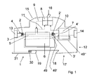
- FIG. 1 shows a schematic view of a service switching device 1 according to the invention, here a circuit breaker, with a housing 12 which has a front side 15 and a mounting side 17.
- the housing 12 On the attachment side 17, the housing 12 has a U-shaped recess which is bounded by a fixed nose 18 and a movable nose 19 attached to a displaceably mounted and resiliently urged by a spring 30 in the direction of the fixed nose 18, for latching the housing 12 on a standard profile support rail, in a conventional manner.
- a contact lever 5 designed as a movable contact bridge is provided in the current path and is provided with two movable contact pieces 3, 3 'which cooperate with two fixed contact pieces 2, 2' to form the double contact point 4, 4 '.
- the contact lever 5 is integrated in a magnetic short-circuit release 6, which comprises a magnetic circuit with an air gap.
- a magnetic short-circuit release is for example from WO 2010/130414 A1 known.
- the contact lever 5 is at least partially disposed in the air gap of the magnetic circuit, so that in the short circuit due to the interaction of the current flow with the magnetic flux within the air gap, an electrodynamic force on the contact lever 5 may arise, the contact lever 5 very quickly in the direction of the Fastened mounting side 17 toward and thus the movable contact pieces 3, 3 'of the fixed contact pieces 2, 2' tears away and the double contact point 4, 4 'thus opens very quickly.
- the opening of the contact points 4, 4 'can take place here in a time of less than a millisecond, which is faster than would be achievable with conventional electromagnetic Schlagankersystemen.
- the overcurrent release 7 is a magnetically acting overcurrent release, as shown for example in the WO 2010/133346 A1 is described.
- the housing 12 has approximately the shape of an inverted T.
- the current path with the magnetic release 6 and the overcurrent release 7 extends substantially in the transverse web of the T-shape.
- a mechanical derailleur 8 which is provided with an actuating lever 16 and can be operated with this, wherein the actuating lever 16 is mounted in a housing fixed axis 32 and protrudes from the front side 15 and from outside the Housing can be operated.
- the rear derailleur 8 is based on that in the DE 10 2008 006 863 A1 described derailleur executed, as well as in the FIG. 2 and in particular in the FIG. 3 becomes clear.
- the latch lever 23 has a slot 24 in which a bracket 25 is guided, the other end to the operating lever, here in Fig. 2 Also referred to as a switching handle 22 is coupled.
- the derailleur includes an intermediate lever 26, one end of which is pivotally coupled to the bracket 25 and the opposite other end to a first end of a locking lever 27.
- the locking lever 27 is pivotally mounted in a housing-fixed axis 33.
- a designed as a leg spring switching mechanism spring 34, one leg 35 is supported fixed to the housing, acts on the locking lever 27 with a force that wants to rotate it clockwise about the axis 33.
- the other end 44 of the locking lever 27 carries an approximately rectangular molded neck portion 45 which carries a plastic pad 46.
- the rear derailleur comprises a designed as a double arm lever hammer 21 which is mounted pivotably about a housing-fixed axis 36 and acts with its first arm 37 when pivoting clockwise on the release lever 20 and pushes it away counterclockwise, so that then the Verklinkungsstelle is unlatched.
- the contact lever 5 by means of a contact pressure spring 38, in Fig. 1 not shown, but see in Fig. 2 , towards the front towards pressed above, so that the double pad 4, 4 'is closed and current can flow.
- a designed as a double arm lever transmission lever 39 is provided which is pivotally mounted about a housing-fixed axis 40.
- Whose first leg 41 is coupled to a neck arm 42 of the contact lever 5, which looks up from the short-circuit current release 6, coupled.
- the second leg 43 of the transmission lever is acted upon by the contact pressure spring 38, here a cylindrical spring, which is supported fixed to the housing with its other end, in the counterclockwise direction. Therefore, the contact pressure spring 38 tries in the on state, as in the FIGS. 1 to 3 is shown, via the transmission lever 39 to pull the contact lever 5 upwards and thus keep the contact points 4, 4 'closed.
- the handle is 22 from his in the Fig. 1 shown in the off position to the left, ie counterclockwise, pivoted.
- the Verklinkungsstelle between the release lever 20 and the latch lever 23 is unlatched inside the derailleur 8 by the release lever is pivoted under the action of the control handle 22 to the right.
- the restoring force of the switching mechanism spring 34 can now pivot the locking lever so clockwise so that he presses the contact bridge 5 down to its opening position with the plastic pad 46 at its neck portion 45, against the restoring force of the contact pressure spring 34.
- the Verklinkungsstelle verklinkt again and the rear derailleur is ready to start again.
- the locking handle 22 is pivoted back into its closed position with latched Verklinkungsstelle. This is the pivoting movement the actuating lever 22 via the lever chain - in the latched state again rigid - implemented in a pushing movement to the left, which acts on the locking lever 27 and pivoted against the restoring force of the switching mechanism spring 34 so that the plastic support 46 at its attachment portion 45, the contact bridge 5 releases. This is immediately pressed by the transmission lever 39 under the action of the contact pressure spring 38 back to its rest position. The double contact 4, 4 'is closed again.
- the pivoting of the hammer in a clockwise direction causes its action on the release lever and a pivoting of the release lever, so that the Verklinkungsstelle the derailleur is unlatched, which, as described above, has the consequence that the contact lever 5 held by the locking lever 27 in the open position becomes.
- the contact point 4, 4 ' has been opened very quickly by the short-circuit current release 6, the rear derailleur has been unlatched and causes a permanent open position of the contact point 4, 4', until it is switched on again by hand.
- FIG. 3 An overcurrent release 7 is also indicated, on whose shaft 48 a cam body 51 is formed, which is also coupled to the hammer 21.
- the assembly of the reversing lever 47 consists of four parts, the actual lever 47, an insert 56, a compression spring and a pin.
- the lever 47 serves as a link between the contact lever 5 and the rear derailleur of the service switching device.
- the reversing lever 47 is placed on a predetermined axis 57 in the lower housing part - hereinafter also referred to as the axis of rotation.
- a pin is designed as a coupling extension, which is inserted into the slot provided in the approach 42 of the contact bridge 5.
- the lever 47 has various tasks to take:
- the lever 47 is initially in the normal position, and the insert 56 is pressed by the compression spring within the recess in the second arm 55 of the reversing lever 47 to the front, in the direction of the front side 15, causing it laterally with its contact surface Distance in the correct position for striking the active extension, a bolt, the impact lever 21 is located.
- the contact bridge 5 is pulled into the magnetic core of the short-circuit release 6 and thereby presses on the pin of the reversing lever 47.
- the lever 47 begins to rotate, and by the contact between the insert 56 and the bolt on the hammer 21 is the hammer 21 as well set in rotation.
- the contact between the insert 56 and the pin of the hammer 21 remains until the triggering of the derailleur takes place.
- the insert member 56 within the reversing lever 47 slightly backwards, in the direction of the mounting side 17, pressed according to a stop curve, which is located on the upper housing shell and then comes with the insert 56 engages when the housing is closed.
- the housing is constructed here namely in the so-called shell construction, it consists of two housing half-shells, which are joined together along a circumferential joining edge.
- the main sub-assemblies of the service switching device are used in the lower half of the housing, to complete the assembly then the upper half of the housing, the upper housing part, placed and connected to the lower part.
- the contact bridge 5 is in the open position, such as when the rear derailleur is locked, so the insert 56 of the reversing lever 47 has left the stop curve of the upper housing part and is pressed by the applied compression spring forward toward the front side 15, whereby the insert 56 a Slide groove into the trajectory of the pin of the hammer and release it for the movement of the hammer.
- the web guide of the second groove is designed so that by the web guide of the second groove and the simultaneous following of the insert 56 along the stop curve of the upper housing part, together with the spring pressure on the insert 56, the hammer 21 is held in its initial position during rotation by the lever 47.
- the reversing lever 47 is designed so that the impact lever 21 can be rotated when triggered by the overcurrent release by the control cam on the control cam body 51, without any influence of the hammer 21 is effected by the lever 47. In this case, the reversing lever 47 remains unaffected until the unlatching of the rear derailleur in its normal position and is then rotated by the locking of the contact bridge 5, as described in point a).
- the overcurrent release 7 is a magnetically acting overcurrent release, as in WO 2010/133346 A1 described. On it a rear derailleur actuator in the form of a rotatably mounted about its longitudinal axis shaft 48 is formed. Furthermore, the overcurrent release 7 comprises an adjustment member 50 in the form of a fetlock spring. In the case of an overcurrent, the magnetic circuit of the overcurrent release exerts a torque on the shaft 48 and tries to turn it clockwise. This will only happen when the drive torque acting on the shaft 48 exceeds the tether moment exerted on the shaft 48 by the tether spring. Thus, the threshold of the overcurrent release 7 is adjustable.
- a cam body 51 is formed at the free end of the shaft 48. This has approximately the shape of a cylinder, which is partially cut laterally.
- a control cam is formed in the control cam body.
- the second arm 53 of the hammer 21 is supported on the control cam.
- the contact point 4, 4 ' has thus been opened by the overcurrent release 7 in the event of an overcurrent by the rotational movement of the shaft 48 of the overcurrent release 7 is converted by means of the control cam 52 in a pivoting movement of the hammer 21, whereby the rear derailleur is unlatched and a permanent open position the contact point 4, 4 'is effected until it is switched on again by hand.
- the installation switching device described above is particularly advantageously used to secure circuits at low nominal voltage, for example, 60V, AC or DC, because because of the caused by the electrodynamic short-circuit current release 6 very fast shutdown of a short circuit current is no arc quenching device required; since the anode-cathode voltage is already so large that it exceeds the 60 V rated voltage, so that the current is interrupted; no additional arc voltage is required to counteract the voltage applied to the terminals for disconnection.
- the installation switching device described above can also be used to advantage in applications with a strongly fluctuating ambient temperature, because due to the overcurrent release operating according to a magnetic principle, no temperature compensation of the overcurrent release is required.
- the present invention also includes any other combinations of preferred embodiments as well as individual design features or refinements, as long as these are not mutually exclusive.
Applications Claiming Priority (1)
| Application Number | Priority Date | Filing Date | Title |
|---|---|---|---|
| DE102011008832A DE102011008832A1 (de) | 2011-01-19 | 2011-01-19 | Installationsschaltgerät |
Publications (1)
| Publication Number | Publication Date |
|---|---|
| EP2479770A1 true EP2479770A1 (fr) | 2012-07-25 |
Family
ID=45440053
Family Applications (1)
| Application Number | Title | Priority Date | Filing Date |
|---|---|---|---|
| EP11010144A Withdrawn EP2479770A1 (fr) | 2011-01-19 | 2011-12-22 | Commutateur d'installation |
Country Status (3)
| Country | Link |
|---|---|
| EP (1) | EP2479770A1 (fr) |
| CN (1) | CN202352597U (fr) |
| DE (1) | DE102011008832A1 (fr) |
Cited By (2)
| Publication number | Priority date | Publication date | Assignee | Title |
|---|---|---|---|---|
| CN109038144A (zh) * | 2018-09-20 | 2018-12-18 | 苏州工业园区斯博自动化控制设备有限公司 | 一种接插件短路机构 |
| CN112687482A (zh) * | 2021-01-22 | 2021-04-20 | 何贵庭 | 一种两轴不同心的连接装置 |
Families Citing this family (1)
| Publication number | Priority date | Publication date | Assignee | Title |
|---|---|---|---|---|
| KR102007779B1 (ko) * | 2018-02-06 | 2019-08-07 | 엘에스산전 주식회사 | 접지스위치를 갖는 개폐장치 |
Citations (6)
| Publication number | Priority date | Publication date | Assignee | Title |
|---|---|---|---|---|
| US4118681A (en) * | 1976-05-12 | 1978-10-03 | Merlin Gerin | High-speed current-limiting device having a contact reclosing retarding member |
| EP0013642A1 (fr) * | 1979-01-11 | 1980-07-23 | Merlin Gerin | Disjoncteur limiteur basse tension |
| WO2005091323A1 (fr) * | 2004-03-17 | 2005-09-29 | Abb Patent Gmbh | Mecanisme de commutation pour appareil de distribution d'installation electrique |
| DE102008006863A1 (de) | 2007-05-23 | 2009-01-22 | Abb Ag | Elektrisches Installationsschaltgerät |
| EP2251887A1 (fr) * | 2009-05-15 | 2010-11-17 | Abb Ag | Dispositif de déclenchement électromagnétique |
| WO2010133346A1 (fr) | 2009-05-19 | 2010-11-25 | Abb Ag | Déclencheur de surintensité indépendant thermiquement |
Family Cites Families (6)
| Publication number | Priority date | Publication date | Assignee | Title |
|---|---|---|---|---|
| JPS5669745A (en) * | 1979-11-10 | 1981-06-11 | Terasaki Denki Sangyo Kk | Circuit breaker |
| DE3030429A1 (de) * | 1980-08-12 | 1982-09-30 | Brown, Boveri & Cie Ag, 6800 Mannheim | Lichtbogenloeschkammer |
| JPS60189134A (ja) * | 1984-03-09 | 1985-09-26 | 寺崎電気産業株式会社 | 回路遮断器 |
| DE8620645U1 (fr) * | 1986-07-31 | 1988-01-28 | Siemens Ag, 1000 Berlin Und 8000 Muenchen, De | |
| FR2768856B1 (fr) * | 1997-09-24 | 1999-11-12 | Schneider Electric Sa | Disjoncteur a declencheur electromagnetique a propulseur d'un contact mobile a fourche |
| FR2807565B1 (fr) * | 2000-04-10 | 2003-03-14 | Schneider Electric Ind Sa | Pole pour un disjoncteur electrique limiteur de basse tension de puissance et disjoncteur muni d'un tel pole |
-
2011
- 2011-01-19 DE DE102011008832A patent/DE102011008832A1/de not_active Withdrawn
- 2011-03-14 CN CN2011201711657U patent/CN202352597U/zh not_active Expired - Fee Related
- 2011-12-22 EP EP11010144A patent/EP2479770A1/fr not_active Withdrawn
Patent Citations (7)
| Publication number | Priority date | Publication date | Assignee | Title |
|---|---|---|---|---|
| US4118681A (en) * | 1976-05-12 | 1978-10-03 | Merlin Gerin | High-speed current-limiting device having a contact reclosing retarding member |
| EP0013642A1 (fr) * | 1979-01-11 | 1980-07-23 | Merlin Gerin | Disjoncteur limiteur basse tension |
| WO2005091323A1 (fr) * | 2004-03-17 | 2005-09-29 | Abb Patent Gmbh | Mecanisme de commutation pour appareil de distribution d'installation electrique |
| DE102008006863A1 (de) | 2007-05-23 | 2009-01-22 | Abb Ag | Elektrisches Installationsschaltgerät |
| EP2251887A1 (fr) * | 2009-05-15 | 2010-11-17 | Abb Ag | Dispositif de déclenchement électromagnétique |
| WO2010130414A1 (fr) | 2009-05-15 | 2010-11-18 | Abb Ag | Dispositif de declenchement electromagnetique |
| WO2010133346A1 (fr) | 2009-05-19 | 2010-11-25 | Abb Ag | Déclencheur de surintensité indépendant thermiquement |
Cited By (2)
| Publication number | Priority date | Publication date | Assignee | Title |
|---|---|---|---|---|
| CN109038144A (zh) * | 2018-09-20 | 2018-12-18 | 苏州工业园区斯博自动化控制设备有限公司 | 一种接插件短路机构 |
| CN112687482A (zh) * | 2021-01-22 | 2021-04-20 | 何贵庭 | 一种两轴不同心的连接装置 |
Also Published As
| Publication number | Publication date |
|---|---|
| CN202352597U (zh) | 2012-07-25 |
| DE102011008832A1 (de) | 2012-07-19 |
Similar Documents
| Publication | Publication Date | Title |
|---|---|---|
| EP1760748B1 (fr) | Appareil de commutation électrique | |
| EP2095387B1 (fr) | Appareil de commutation d'installation comprenant un blocage double | |
| EP1760747B1 (fr) | Disjoncteur électrique | |
| EP2479771A1 (fr) | Commutateur d'installation | |
| DE102010035857B4 (de) | Installationsschaltgerät mit einem Magnetsystem | |
| DE102011008833B4 (de) | Überstromauslöser und Installationsschaltgerät mit Überstromauslöser | |
| EP2479770A1 (fr) | Commutateur d'installation | |
| EP2479773A1 (fr) | Commutateur d'installation | |
| EP2105941B1 (fr) | Commutateur d'installation doté d'une double coupure | |
| DE102011008829B4 (de) | Installationsschaltgerät | |
| EP2095388B1 (fr) | Appareil de commutation d'installation comprenant un blocage double | |
| EP2087500B1 (fr) | Appareil de commutation d'installation à double coupure | |
| EP1045416A2 (fr) | Déclencheur électromagnétique pour un disjoncteur électrique | |
| DE69833637T2 (de) | Selektiver Auslöser für Leistungsschalter | |
| DE2302039A1 (de) | Elektrischer schalter mit handbetaetigungsglied und stromabhaengig wirkender ausloeseeinheit | |
| EP0371419A2 (fr) | Disjoncteur électrique | |
| DE102010004641B4 (de) | Elektromagnetisches Auslösesystem und Installationsschaltgerät mit einem elektromagnetischen Auslösesystem | |
| EP1659604B1 (fr) | Appareil de commutation pour une installation électrique | |
| DE10141123B4 (de) | Auslöseeinheit für Leistungsschalter | |
| DE102011079593B4 (de) | Elektromechanisches Schutzschaltgerät | |
| EP1498926A2 (fr) | Système de contact avec déclencheur magnétique | |
| WO2007036282A1 (fr) | Appareil d'installation electrique | |
| CH650101A5 (de) | Ueberstromschalter. | |
| DE102008017273A1 (de) | Elektrischer Selbstschalter |
Legal Events
| Date | Code | Title | Description |
|---|---|---|---|
| PUAI | Public reference made under article 153(3) epc to a published international application that has entered the european phase |
Free format text: ORIGINAL CODE: 0009012 |
|
| AK | Designated contracting states |
Kind code of ref document: A1 Designated state(s): AL AT BE BG CH CY CZ DE DK EE ES FI FR GB GR HR HU IE IS IT LI LT LU LV MC MK MT NL NO PL PT RO RS SE SI SK SM TR |
|
| AX | Request for extension of the european patent |
Extension state: BA ME |
|
| 17P | Request for examination filed |
Effective date: 20130111 |
|
| STAA | Information on the status of an ep patent application or granted ep patent |
Free format text: STATUS: THE APPLICATION IS DEEMED TO BE WITHDRAWN |
|
| 18D | Application deemed to be withdrawn |
Effective date: 20140701 |