EP2479770A1 - Installation switching device - Google Patents
Installation switching device Download PDFInfo
- Publication number
- EP2479770A1 EP2479770A1 EP11010144A EP11010144A EP2479770A1 EP 2479770 A1 EP2479770 A1 EP 2479770A1 EP 11010144 A EP11010144 A EP 11010144A EP 11010144 A EP11010144 A EP 11010144A EP 2479770 A1 EP2479770 A1 EP 2479770A1
- Authority
- EP
- European Patent Office
- Prior art keywords
- lever
- contact
- switching device
- release
- service switching
- Prior art date
- Legal status (The legal status is an assumption and is not a legal conclusion. Google has not performed a legal analysis and makes no representation as to the accuracy of the status listed.)
- Withdrawn
Links
Images


Classifications
-
- H—ELECTRICITY
- H01—ELECTRIC ELEMENTS
- H01H—ELECTRIC SWITCHES; RELAYS; SELECTORS; EMERGENCY PROTECTIVE DEVICES
- H01H77/00—Protective overload circuit-breaking switches operated by excess current and requiring separate action for resetting
- H01H77/02—Protective overload circuit-breaking switches operated by excess current and requiring separate action for resetting in which the excess current itself provides the energy for opening the contacts, and having a separate reset mechanism
- H01H77/10—Protective overload circuit-breaking switches operated by excess current and requiring separate action for resetting in which the excess current itself provides the energy for opening the contacts, and having a separate reset mechanism with electrodynamic opening
- H01H77/107—Protective overload circuit-breaking switches operated by excess current and requiring separate action for resetting in which the excess current itself provides the energy for opening the contacts, and having a separate reset mechanism with electrodynamic opening characterised by the blow-off force generating means, e.g. current loops
- H01H77/108—Protective overload circuit-breaking switches operated by excess current and requiring separate action for resetting in which the excess current itself provides the energy for opening the contacts, and having a separate reset mechanism with electrodynamic opening characterised by the blow-off force generating means, e.g. current loops comprising magnetisable elements, e.g. flux concentrator, linear slot motor
-
- H—ELECTRICITY
- H01—ELECTRIC ELEMENTS
- H01H—ELECTRIC SWITCHES; RELAYS; SELECTORS; EMERGENCY PROTECTIVE DEVICES
- H01H71/00—Details of the protective switches or relays covered by groups H01H73/00 - H01H83/00
- H01H71/10—Operating or release mechanisms
- H01H71/12—Automatic release mechanisms with or without manual release
- H01H71/24—Electromagnetic mechanisms
- H01H71/2418—Electromagnetic mechanisms combined with an electrodynamic current limiting mechanism
-
- H—ELECTRICITY
- H01—ELECTRIC ELEMENTS
- H01H—ELECTRIC SWITCHES; RELAYS; SELECTORS; EMERGENCY PROTECTIVE DEVICES
- H01H71/00—Details of the protective switches or relays covered by groups H01H73/00 - H01H83/00
- H01H71/10—Operating or release mechanisms
- H01H71/12—Automatic release mechanisms with or without manual release
- H01H71/40—Combined electrothermal and electromagnetic mechanisms
-
- H—ELECTRICITY
- H01—ELECTRIC ELEMENTS
- H01H—ELECTRIC SWITCHES; RELAYS; SELECTORS; EMERGENCY PROTECTIVE DEVICES
- H01H71/00—Details of the protective switches or relays covered by groups H01H73/00 - H01H83/00
- H01H71/10—Operating or release mechanisms
- H01H71/12—Automatic release mechanisms with or without manual release
- H01H71/24—Electromagnetic mechanisms
- H01H71/2454—Electromagnetic mechanisms characterised by the magnetic circuit or active magnetic elements
-
- H—ELECTRICITY
- H01—ELECTRIC ELEMENTS
- H01H—ELECTRIC SWITCHES; RELAYS; SELECTORS; EMERGENCY PROTECTIVE DEVICES
- H01H73/00—Protective overload circuit-breaking switches in which excess current opens the contacts by automatic release of mechanical energy stored by previous operation of a hand reset mechanism
- H01H73/02—Details
- H01H73/04—Contacts
- H01H73/045—Bridging contacts
Definitions
- the invention relates to an electrical service switching device having a current path which runs in a housing between a first and a second terminal, and which can be opened and closed at least one contact point comprising a fixed and a movable contact piece, with at least one of the current of the current path partially flowed contact lever, which is provided with the at least one movable contact piece, with an electromagnetic short-circuit current release comprising a magnetic circuit with air gap, and with a derailleur which comprises a pivotable between a rest position and a release position impact lever, according to the preamble of claim 1.
- Generic installation switching devices may be, for example, circuit breaker, residual current device, motor protection switch or selective main line circuit breaker.
- a generic circuit breaker is for example in the DE 10 2008 006 863 A1 shown.
- the disconnection of a short-circuit current by means of a percussion armature takes place.
- the field of a current flowing through the solenoid energizes the magnetic circuit within the electromagnetic short-circuit current release, by electrodynamic interaction of the impact armature is moved.
- a striker is coupled, which strikes the contact lever, so that the contact point is opened, and at the same time acts on the rear derailleur, which leads to the unlatching of the derailleur and thus for permanent keeping open the contact point, until the rear derailleur latched again and the contact point can then be closed again.
- the overcurrent release occurs in known service switching devices using a thermo-mechanical release element, usually a strip of bimetallic strip.
- the overcurrent causes heating of the bimetallic strip and its resulting deflection.
- the switching mechanism In the bent state of the bimetallic strip unlatched via a corresponding connection by means of a Wegsbettechnik Trentsgliedes the switching mechanism, whereupon the contact point is also permanently open, until the rear derailleur is latched and the contact point can then be closed again.
- the contact lever In a circuit breaker, the contact lever is usually designed as a pivotally mounted on a single-arm or double arm lever, at one free end, the movable contact piece is attached.
- a motor protection switch In a motor protection switch is usually used as a contact lever sliding a double contact bridge, which carries at its two free ends depending on a movable contact piece, which cooperate two movable contact pieces, each with a fixed contact piece, so that thus two contact points are formed and the switching power is on two contact points can distribute so that each individual contact point is less heavily charged in a short-circuit shutdown.
- the contact lever is at least partially disposed in the air gap of the magnetic circuit, so that in the case of short circuit due to the interaction of the current flow with the magnetic flux within the air gap leading to a rapid opening of the at least one contact point electrodynamic force on the contact lever can arise, and Derailleur acts on a first operative connection line on the contact lever for opening and / or keeping open the Contact point, and in the case of a short-circuit release of the contact lever acts on a third operative connection line on the derailleur to keep open the contact point, wherein the contact lever is coupled via a lever with the hammer.
- An inventive installation switching device has the advantage that the short circuit current shutdown is faster than in a conventionally known device, the other functional characteristics, such as the overcurrent release, the permanent keeping open the contact point after unlatching the rear derailleur, the reconnection after re-latching the rear derailleur, etc., continue to be available as usual.
- the magnetic short-circuit current release as used in the service switching device according to the invention has the advantage that a direct interaction between the magnetic flux or field of the magnetic circuit and the contact lever can take place.
- the opening of the contact point can be done much faster than in the prior art used in circuit breakers Schlagankersystemen, in which yes, as already mentioned, due to the mechanical inertia of the participating moving components, the release speed is limited.
- a force which results on the known as Lorentz force force of a magnetic field on an electric charge moved in the field acts on the contact lever, a force which results on the known as Lorentz force force of a magnetic field on an electric charge moved in the field. This force effect is immediate, without the interposition of mechanical components such as movable armature or striker.
- the contact lever acts according to the invention even on the rear derailleur to its open position.
- the contact lever thus assumes an additional function according to the invention, in addition to the carrying of the movable contact still that of the unlatching of the switching mechanism.
- overcurrent tripping the opening and keeping the contact point open as known about the rear derailleur.
- the lever is a Doppelarmhebel and pivotally mounted in a housing-fixed axis, wherein a first partial arm of the reversing lever with the contact lever and a second arm of the reversing lever are coupled to the hammer.
- an insert is mounted longitudinally displaceably in a recess of the second arm of the reversing lever and resiliently acted upon in the direction of the front side of the housing, wherein the insert produces the coupling to the percussion lever.
- an insert facing the insert knockout and formed on the insert a the Wirkfortsatz facing groove on the hammer, wherein in a first position of the insert of the reaction extension of the hammer on the insert is supported, and wherein in a second position of the Insert part of the active extension of the hammer in the groove is slidably received.
- the contact lever is designed as a movable contact bridge, which is provided with two movable contact pieces which cooperate with two fixed contact pieces to form two contact points, wherein the contact lever is acted upon by the restoring force of a contact pressure spring towards the fixed contact pieces is.
- a transmission lever is provided and mounted pivotably in a housing-fixed axis, wherein the transmission lever transmits the restoring force of the contact pressure spring on the contact lever.
- a projection with a slot is formed on the contact lever, and on the reversing lever a coupling extension is formed, which is guided in the slot.
- the rear derailleur is provided with a locking lever, one end of which carries a neck portion, wherein applied at a caused by the derailleur opening or keeping open the contact point of the locking lever with its attachment part the contact lever for opening the contact point.
- the attachment part carries a plastic pad to improve the sliding properties when the attachment part presses on the approach to the contact lever.
- the advantageous effect according to the invention is the following.
- the contact force is generated by the contact pressure spring via the contact lever.
- the contact bridge is opened via the locking lever.
- the special shape of the plastic overlay ensures that a distance between the contact bridge and locking lever is ensured even when sinking the contact bridge by burning while the required contact opening distance is achieved in the off state.
- the service switching device is provided with an overcurrent release comprising a derailleur actuator which transitions from a rest position to a release position in the event of an overcurrent trip, and in the event of an overcurrent trip, the overcurrent trip device acts on the derailleur to open and keep open via a second operative connection line the contact point through the rear derailleur.
- the derailleur actuator of the overcurrent release is coupled to an overcurrent magnetic circuit, wherein the force acting on the derailleur actuator force is caused by the magnetic field of the overcurrent, wherein the derailleur actuator is coupled to an electromagnetic damping element for adjusting the tripping delay time, and wherein Derailleur actuator for adjusting the overcurrent trip threshold is coupled to an adjusting member.
- the overcurrent release is realized as a magnetic trip system. This has the advantage that the overcurrent release can be temperature independent. For in the known in the prior art Thermobimetallauslösern the bimetal deformed even with a change in the ambient temperature, which is why such an overcurrent release according to the prior art usually has to be coupled with a compensation device. The invention in the service switching device used magnetic overcurrent release shows no temperature dependence.
- a preferred embodiment provides that the short-circuit current release and the overcurrent release in the flow direction of the current through the current path are arranged one behind the other in the housing. This allows a particularly good use of space.
- the housing has approximately the shape of an inverted T, with a front side, and is provided at the front with an operating lever for manual operation of the derailleur, wherein the switching mechanism between the short-circuit current release and the front side arranged in the housing.
- the switching mechanism is arranged in the region of the longitudinal web of the T-shape of the housing, and the overcurrent release and the short-circuit release are arranged in the region of the transverse web of the T-shape of the housing.
- the housing has a front side opposite mounting side, which is provided with fastening means for locking the housing on a standard profile support rail.
- a fastener is in a preferred embodiment, an approximately U-shaped recess which is bounded by a fixed nose and attached to a displaceably mounted and resiliently acted upon in the direction of the fixed nose towards slide movable nose.
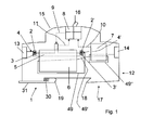
- FIG. 1 shows a schematic view of a service switching device 1 according to the invention, here a circuit breaker, with a housing 12 which has a front side 15 and a mounting side 17.
- the housing 12 On the attachment side 17, the housing 12 has a U-shaped recess which is bounded by a fixed nose 18 and a movable nose 19 attached to a displaceably mounted and resiliently urged by a spring 30 in the direction of the fixed nose 18, for latching the housing 12 on a standard profile support rail, in a conventional manner.
- a contact lever 5 designed as a movable contact bridge is provided in the current path and is provided with two movable contact pieces 3, 3 'which cooperate with two fixed contact pieces 2, 2' to form the double contact point 4, 4 '.
- the contact lever 5 is integrated in a magnetic short-circuit release 6, which comprises a magnetic circuit with an air gap.
- a magnetic short-circuit release is for example from WO 2010/130414 A1 known.
- the contact lever 5 is at least partially disposed in the air gap of the magnetic circuit, so that in the short circuit due to the interaction of the current flow with the magnetic flux within the air gap, an electrodynamic force on the contact lever 5 may arise, the contact lever 5 very quickly in the direction of the Fastened mounting side 17 toward and thus the movable contact pieces 3, 3 'of the fixed contact pieces 2, 2' tears away and the double contact point 4, 4 'thus opens very quickly.
- the opening of the contact points 4, 4 'can take place here in a time of less than a millisecond, which is faster than would be achievable with conventional electromagnetic Schlagankersystemen.
- the overcurrent release 7 is a magnetically acting overcurrent release, as shown for example in the WO 2010/133346 A1 is described.
- the housing 12 has approximately the shape of an inverted T.
- the current path with the magnetic release 6 and the overcurrent release 7 extends substantially in the transverse web of the T-shape.
- a mechanical derailleur 8 which is provided with an actuating lever 16 and can be operated with this, wherein the actuating lever 16 is mounted in a housing fixed axis 32 and protrudes from the front side 15 and from outside the Housing can be operated.
- the rear derailleur 8 is based on that in the DE 10 2008 006 863 A1 described derailleur executed, as well as in the FIG. 2 and in particular in the FIG. 3 becomes clear.
- the latch lever 23 has a slot 24 in which a bracket 25 is guided, the other end to the operating lever, here in Fig. 2 Also referred to as a switching handle 22 is coupled.
- the derailleur includes an intermediate lever 26, one end of which is pivotally coupled to the bracket 25 and the opposite other end to a first end of a locking lever 27.
- the locking lever 27 is pivotally mounted in a housing-fixed axis 33.
- a designed as a leg spring switching mechanism spring 34, one leg 35 is supported fixed to the housing, acts on the locking lever 27 with a force that wants to rotate it clockwise about the axis 33.
- the other end 44 of the locking lever 27 carries an approximately rectangular molded neck portion 45 which carries a plastic pad 46.
- the rear derailleur comprises a designed as a double arm lever hammer 21 which is mounted pivotably about a housing-fixed axis 36 and acts with its first arm 37 when pivoting clockwise on the release lever 20 and pushes it away counterclockwise, so that then the Verklinkungsstelle is unlatched.
- the contact lever 5 by means of a contact pressure spring 38, in Fig. 1 not shown, but see in Fig. 2 , towards the front towards pressed above, so that the double pad 4, 4 'is closed and current can flow.
- a designed as a double arm lever transmission lever 39 is provided which is pivotally mounted about a housing-fixed axis 40.
- Whose first leg 41 is coupled to a neck arm 42 of the contact lever 5, which looks up from the short-circuit current release 6, coupled.
- the second leg 43 of the transmission lever is acted upon by the contact pressure spring 38, here a cylindrical spring, which is supported fixed to the housing with its other end, in the counterclockwise direction. Therefore, the contact pressure spring 38 tries in the on state, as in the FIGS. 1 to 3 is shown, via the transmission lever 39 to pull the contact lever 5 upwards and thus keep the contact points 4, 4 'closed.
- the handle is 22 from his in the Fig. 1 shown in the off position to the left, ie counterclockwise, pivoted.
- the Verklinkungsstelle between the release lever 20 and the latch lever 23 is unlatched inside the derailleur 8 by the release lever is pivoted under the action of the control handle 22 to the right.
- the restoring force of the switching mechanism spring 34 can now pivot the locking lever so clockwise so that he presses the contact bridge 5 down to its opening position with the plastic pad 46 at its neck portion 45, against the restoring force of the contact pressure spring 34.
- the Verklinkungsstelle verklinkt again and the rear derailleur is ready to start again.
- the locking handle 22 is pivoted back into its closed position with latched Verklinkungsstelle. This is the pivoting movement the actuating lever 22 via the lever chain - in the latched state again rigid - implemented in a pushing movement to the left, which acts on the locking lever 27 and pivoted against the restoring force of the switching mechanism spring 34 so that the plastic support 46 at its attachment portion 45, the contact bridge 5 releases. This is immediately pressed by the transmission lever 39 under the action of the contact pressure spring 38 back to its rest position. The double contact 4, 4 'is closed again.
- the pivoting of the hammer in a clockwise direction causes its action on the release lever and a pivoting of the release lever, so that the Verklinkungsstelle the derailleur is unlatched, which, as described above, has the consequence that the contact lever 5 held by the locking lever 27 in the open position becomes.
- the contact point 4, 4 ' has been opened very quickly by the short-circuit current release 6, the rear derailleur has been unlatched and causes a permanent open position of the contact point 4, 4', until it is switched on again by hand.
- FIG. 3 An overcurrent release 7 is also indicated, on whose shaft 48 a cam body 51 is formed, which is also coupled to the hammer 21.
- the assembly of the reversing lever 47 consists of four parts, the actual lever 47, an insert 56, a compression spring and a pin.
- the lever 47 serves as a link between the contact lever 5 and the rear derailleur of the service switching device.
- the reversing lever 47 is placed on a predetermined axis 57 in the lower housing part - hereinafter also referred to as the axis of rotation.
- a pin is designed as a coupling extension, which is inserted into the slot provided in the approach 42 of the contact bridge 5.
- the lever 47 has various tasks to take:
- the lever 47 is initially in the normal position, and the insert 56 is pressed by the compression spring within the recess in the second arm 55 of the reversing lever 47 to the front, in the direction of the front side 15, causing it laterally with its contact surface Distance in the correct position for striking the active extension, a bolt, the impact lever 21 is located.
- the contact bridge 5 is pulled into the magnetic core of the short-circuit release 6 and thereby presses on the pin of the reversing lever 47.
- the lever 47 begins to rotate, and by the contact between the insert 56 and the bolt on the hammer 21 is the hammer 21 as well set in rotation.
- the contact between the insert 56 and the pin of the hammer 21 remains until the triggering of the derailleur takes place.
- the insert member 56 within the reversing lever 47 slightly backwards, in the direction of the mounting side 17, pressed according to a stop curve, which is located on the upper housing shell and then comes with the insert 56 engages when the housing is closed.
- the housing is constructed here namely in the so-called shell construction, it consists of two housing half-shells, which are joined together along a circumferential joining edge.
- the main sub-assemblies of the service switching device are used in the lower half of the housing, to complete the assembly then the upper half of the housing, the upper housing part, placed and connected to the lower part.
- the contact bridge 5 is in the open position, such as when the rear derailleur is locked, so the insert 56 of the reversing lever 47 has left the stop curve of the upper housing part and is pressed by the applied compression spring forward toward the front side 15, whereby the insert 56 a Slide groove into the trajectory of the pin of the hammer and release it for the movement of the hammer.
- the web guide of the second groove is designed so that by the web guide of the second groove and the simultaneous following of the insert 56 along the stop curve of the upper housing part, together with the spring pressure on the insert 56, the hammer 21 is held in its initial position during rotation by the lever 47.
- the reversing lever 47 is designed so that the impact lever 21 can be rotated when triggered by the overcurrent release by the control cam on the control cam body 51, without any influence of the hammer 21 is effected by the lever 47. In this case, the reversing lever 47 remains unaffected until the unlatching of the rear derailleur in its normal position and is then rotated by the locking of the contact bridge 5, as described in point a).
- the overcurrent release 7 is a magnetically acting overcurrent release, as in WO 2010/133346 A1 described. On it a rear derailleur actuator in the form of a rotatably mounted about its longitudinal axis shaft 48 is formed. Furthermore, the overcurrent release 7 comprises an adjustment member 50 in the form of a fetlock spring. In the case of an overcurrent, the magnetic circuit of the overcurrent release exerts a torque on the shaft 48 and tries to turn it clockwise. This will only happen when the drive torque acting on the shaft 48 exceeds the tether moment exerted on the shaft 48 by the tether spring. Thus, the threshold of the overcurrent release 7 is adjustable.
- a cam body 51 is formed at the free end of the shaft 48. This has approximately the shape of a cylinder, which is partially cut laterally.
- a control cam is formed in the control cam body.
- the second arm 53 of the hammer 21 is supported on the control cam.
- the contact point 4, 4 ' has thus been opened by the overcurrent release 7 in the event of an overcurrent by the rotational movement of the shaft 48 of the overcurrent release 7 is converted by means of the control cam 52 in a pivoting movement of the hammer 21, whereby the rear derailleur is unlatched and a permanent open position the contact point 4, 4 'is effected until it is switched on again by hand.
- the installation switching device described above is particularly advantageously used to secure circuits at low nominal voltage, for example, 60V, AC or DC, because because of the caused by the electrodynamic short-circuit current release 6 very fast shutdown of a short circuit current is no arc quenching device required; since the anode-cathode voltage is already so large that it exceeds the 60 V rated voltage, so that the current is interrupted; no additional arc voltage is required to counteract the voltage applied to the terminals for disconnection.
- the installation switching device described above can also be used to advantage in applications with a strongly fluctuating ambient temperature, because due to the overcurrent release operating according to a magnetic principle, no temperature compensation of the overcurrent release is required.
- the present invention also includes any other combinations of preferred embodiments as well as individual design features or refinements, as long as these are not mutually exclusive.
Abstract
Description
Die Erfindung betrifft ein elektrisches Installationsschaltgerät mit einem Strompfad, der in einem Gehäuse zwischen einer ersten und einer zweiten Anschlussklemme verläuft, und der an wenigstens einer ein feststehendes und ein bewegliches Kontaktstück umfassenden Kontaktstelle geöffnet und geschlossen werden kann, mit einem von dem Strom des Strompfades wenigstens teilweise durchflossenen Kontakthebel, der mit dem wenigstens einen beweglichen Kontaktstück versehen ist, mit einem elektromagnetischen Kurzschlussstromauslöser der einen Magnetkreis mit Luftspalt umfasst, und mit einem Schaltwerk, das einen zwischen einer Ruhelage und einer Auslösungslage verschwenkbaren Schlaghebel umfasst, gemäß dem Oberbegriff des Anspruchs 1.The invention relates to an electrical service switching device having a current path which runs in a housing between a first and a second terminal, and which can be opened and closed at least one contact point comprising a fixed and a movable contact piece, with at least one of the current of the current path partially flowed contact lever, which is provided with the at least one movable contact piece, with an electromagnetic short-circuit current release comprising a magnetic circuit with air gap, and with a derailleur which comprises a pivotable between a rest position and a release position impact lever, according to the preamble of
Gattungsgemäße Installationsschaltgeräte können beispielsweise Leitungsschutzschalter, Fehlerstromschutzschalter, Motorschutzschalter oder selektive Hauptleitungsschutzschalter sein.Generic installation switching devices may be, for example, circuit breaker, residual current device, motor protection switch or selective main line circuit breaker.
Ein gattungsgemäßer Leistungsschutzschalter ist beispielsweise in der
Die Überstromauslösung erfolgt bei bekannten Installationsschaltgeräten mit Hilfe eines thermomechanischen Auslöseelementes, meistens eines Streifens aus Thermobimetall. Der Überstrom verursacht eine Erwärmung des Thermobimetallstreifens und dessen daraus resultierende Ausbiegung. In ausgebogenem Zustand entklinkt der Thermobimetallstreifen über eine entsprechende Anbindung mittels eines Schaltwerkbetätigungsgliedes das Schaltwerk, worauf hin die Kontaktstelle ebenfalls dauerhaft geöffnet wird, so lange, bis das Schaltwerk wieder verklinkt wird und die Kontaktstelle daraufhin erst wieder geschlossen werden kann.The overcurrent release occurs in known service switching devices using a thermo-mechanical release element, usually a strip of bimetallic strip. The overcurrent causes heating of the bimetallic strip and its resulting deflection. In the bent state of the bimetallic strip unlatched via a corresponding connection by means of a Schaltwerksbetätigungsgliedes the switching mechanism, whereupon the contact point is also permanently open, until the rear derailleur is latched and the contact point can then be closed again.
Bei einem Leitungsschutzschalter ist der Kontakthebel meistens als an einer Achse schwenkbar gelagerter einarmiger oder Doppelarmhebel ausgeführt, an dessen einem freien Ende das bewegliche Kontaktstück befestigt ist. Bei einem Motorschutzschalter wird als Kontakthebel üblicherweise eine verschieblich gelagerte Doppelkontaktbrücke verwendet, die an ihren beiden freien Enden je ein bewegliches Kontaktstück trägt, welche beiden beweglichen Kontaktstücke mit je einem festen Kontaktstück zusammenwirken, so dass damit zwei Kontaktstellen gebildet sind und die Schaltleistung sich auf zwei Kontaktstellen verteilen kann, so dass jede einzelne Kontaktstelle bei einer Kurzschlussabschaltung weniger stark belastet wird.In a circuit breaker, the contact lever is usually designed as a pivotally mounted on a single-arm or double arm lever, at one free end, the movable contact piece is attached. In a motor protection switch is usually used as a contact lever sliding a double contact bridge, which carries at its two free ends depending on a movable contact piece, which cooperate two movable contact pieces, each with a fixed contact piece, so that thus two contact points are formed and the switching power is on two contact points can distribute so that each individual contact point is less heavily charged in a short-circuit shutdown.
Bei bekannten Installationsschaltgeräten ist jedoch die Ansprechgeschwindigkeit des Magnetauslösers begrenzt, da mehrere mechanische Teilsysteme umfasst sind, deren jedes eine gewisse mechanische Trägheit hat. Damit ist auch die Strombegrenzung im Kurzschlussfall begrenzt.In known service switching devices, however, the response speed of the magnetic release is limited because several mechanical subsystems are included, each of which has a certain mechanical inertia. This also limits the current limit in the event of a short circuit.
Es ist daher die Aufgabe der vorliegenden Erfindung, ein gattungsgemäßes Installationsschaltgerät so weiterzubilden, dass eine schnellere Kurzschlussstromabschaltung erreicht werden kann.It is therefore the object of the present invention to develop a generic service switching device so that a faster short-circuit power cut can be achieved.
Die Aufgabe wird gelöst durch ein gattungsgemäßes Installationsschaltgerät mit den kennzeichnenden Merkmalen des Anspruchs 1.The object is achieved by a generic service switching device with the characterizing features of
Erfindungsgemäß also ist der Kontakthebel zumindest teilweise in dem Luftspalt des Magnetkreises angeordnet, so dass im Kurzschlussfall aufgrund der Wechselwirkung des Stromflusses mit dem magnetischen Fluss innerhalb des Luftspaltes eine zu einer schnellen Öffnung der wenigstens einen Kontaktstelle führende elektrodynamische Kraftwirkung auf den Kontakthebel entstehen kann, und das Schaltwerk wirkt über eine erste Wirkverbindungslinie auf den Kontakthebel zum Öffnen und/oder Offenhalten der Kontaktstelle, und im Fall einer Kurzschlussauslösung wirkt der Kontakthebel über eine dritte Wirkverbindungslinie auf das Schaltwerk zum Offenhalten der Kontaktstelle, wobei der Kontakthebel über einen Umlenkhebel mit dem Schlaghebel gekoppelt ist.According to the invention, the contact lever is at least partially disposed in the air gap of the magnetic circuit, so that in the case of short circuit due to the interaction of the current flow with the magnetic flux within the air gap leading to a rapid opening of the at least one contact point electrodynamic force on the contact lever can arise, and Derailleur acts on a first operative connection line on the contact lever for opening and / or keeping open the Contact point, and in the case of a short-circuit release of the contact lever acts on a third operative connection line on the derailleur to keep open the contact point, wherein the contact lever is coupled via a lever with the hammer.
Ein erfindungsgemäßes Installationsschaltgerät hat den Vorteil, dass die Kurzschlussstromabschaltung schneller erfolgt als bei einem herkömmlich bekannten Gerät, wobei die weiteren funktionalen Eigenschaften, wie die Überstromauslösung, die dauerhafte Offenhaltung der Kontaktstelle nach Entklinken des Schaltwerks, das Wiedereinschalten nach erneuter Verklinkung des Schaltwerks, etc., weiterhin wie gewohnt zur Verfügung stehen.An inventive installation switching device has the advantage that the short circuit current shutdown is faster than in a conventionally known device, the other functional characteristics, such as the overcurrent release, the permanent keeping open the contact point after unlatching the rear derailleur, the reconnection after re-latching the rear derailleur, etc., continue to be available as usual.
Die magnetische Kurzschlussstromauslösung wie in dem erfindungsgemäßen Installationsschaltgerät verwendet hat den Vorteil, dass eine direkte Wechselwirkung zwischen dem magnetischen Fluss oder Feld des Magnetkreises und dem Kontakthebel stattfinden kann. Dadurch kann die Öffnung der Kontaktstelle sehr viel schneller erfolgen als bei im Stand der Technik in Leitungsschutzschaltern verwendeten Schlagankersystemen, bei denen ja, wie bereits erwähnt, aufgrund der mechanischen Trägheit der beteiligten beweglichen Komponenten, die Auslösegeschwindigkeit begrenzt ist. Bei der magnetischen Kurzschlussstromauslösung wie in dem erfindungsgemäßen Installationsschaltgerät verwendet wirkt auf den Kontakthebel eine Kraft, die auf der als Lorentz-Kraft bekannten Kraftwirkung eines magnetischen Feldes auf eine in dem Feld bewegte elektrische Ladung resultiert. Diese Kraftwirkung erfolgt unmittelbar, ohne Zwischenschaltung mechanischer Komponenten wie beweglicher Anker oder Schlagstift. Um eine dauerhafte Offenhaltung der Kontaktstelle zu gewährleisten, wirkt erfindungsgemäß der Kontakthebel selbst auf das Schaltwerk zu dessen Offenhaltung. Der Kontakthebel übernimmt erfindungsgemäß also eine zusätzliche Funktion, neben der des Tragens des beweglichen Kontaktes noch diejenige der Entklinkung des Schaltwerkes. Im Fall der Überstromauslösung erfolgt die Öffnung und Offenhaltung der Kontaktstelle wie bekannt über das Schaltwerk.The magnetic short-circuit current release as used in the service switching device according to the invention has the advantage that a direct interaction between the magnetic flux or field of the magnetic circuit and the contact lever can take place. Thus, the opening of the contact point can be done much faster than in the prior art used in circuit breakers Schlagankersystemen, in which yes, as already mentioned, due to the mechanical inertia of the participating moving components, the release speed is limited. When used in the magnetic short-circuit current trip as in the service switching device according to the invention acts on the contact lever, a force which results on the known as Lorentz force force of a magnetic field on an electric charge moved in the field. This force effect is immediate, without the interposition of mechanical components such as movable armature or striker. In order to ensure a permanent open position of the contact point, the contact lever acts according to the invention even on the rear derailleur to its open position. The contact lever thus assumes an additional function according to the invention, in addition to the carrying of the movable contact still that of the unlatching of the switching mechanism. In the case of overcurrent tripping the opening and keeping the contact point open as known about the rear derailleur.
Gemäß einer vorteilhaften Ausführungsform der Erfindung ist der Umlenkhebel ein Doppelarmhebel und in einer gehäusefesten Achse verschwenkbar gelagert, wobei ein erster Teilarm des Umlenkhebels mit dem Kontakthebel und ein zweiter Teilarm des Umlenkhebels mit dem Schlaghebel gekoppelt sind.According to an advantageous embodiment of the invention, the lever is a Doppelarmhebel and pivotally mounted in a housing-fixed axis, wherein a first partial arm of the reversing lever with the contact lever and a second arm of the reversing lever are coupled to the hammer.
Gemäß einer vorteilhaften Ausführungsform der Erfindung ist in einer Aussparung des zweiten Arms des Umlenkhebels ein Einlegeteil längsverschieblich gelagert und in Richtung auf die Frontseite des Gehäuses hin federnd beaufschlagt, wobei das Einlegeteil die Kopplung zu dem Schlaghebel herstellt.According to an advantageous embodiment of the invention, an insert is mounted longitudinally displaceably in a recess of the second arm of the reversing lever and resiliently acted upon in the direction of the front side of the housing, wherein the insert produces the coupling to the percussion lever.
Gemäß einer vorteilhaften Ausführungsform der Erfindung sind an dem Schlaghebel ein dem Einlegeteil zugewandter Wirkfortsatz und an dem Einlegeteil eine dem Wirkfortsatz zugewandte Nut ausgebildet, wobei in einer ersten Stellung des Einlegeteils der Wirkfortsatz des Schlaghebels an dem Einlegeteil sich abstützt, und wobei in einer zweiten Stellung des Einlegeteils der Wirkfortsatz des Schlaghebels in der Nut verschieblich aufgenommen ist.According to an advantageous embodiment of the invention, an insert facing the insert knockout and formed on the insert a the Wirkfortsatz facing groove on the hammer, wherein in a first position of the insert of the reaction extension of the hammer on the insert is supported, and wherein in a second position of the Insert part of the active extension of the hammer in the groove is slidably received.
Gemäß einer vorteilhaften Ausführungsform der Erfindung ist der Kontakthebel als bewegliche Kontaktbrücke ausgebildet, die mit zwei beweglichen Kontaktstücken versehen ist, welche mit zwei feststehenden Kontaktstücken zur Bildung zweier Kontaktstellen zusammenwirken, wobei der Kontakthebel durch die rückstellende Kraft einer Kontaktdruckfeder in Richtung zu den feststehenden Kontaktstücken hin beaufschlagt ist. Damit ist eine Doppelkontaktstelle geschaffen, die den Vorteil hat, dass jede einzelne Teil-Kontaktstelle bei einer Kurzschlussstromabschaltung weniger stark belastet wird als bei einer einzigen Kontaktstelle.According to an advantageous embodiment of the invention, the contact lever is designed as a movable contact bridge, which is provided with two movable contact pieces which cooperate with two fixed contact pieces to form two contact points, wherein the contact lever is acted upon by the restoring force of a contact pressure spring towards the fixed contact pieces is. Thus, a double contact point is created, which has the advantage that each individual part contact point is less heavily loaded in a short-circuit power cut than a single contact point.
Gemäß einer vorteilhaften Ausführungsform der Erfindung ist ein Übertragungshebel vorgesehen und in einer gehäusefesten Achse verschwenkbar gelagert, wobei der Übertragungshebel die rückstellende Kraft der Kontaktdruckfeder auf den Kontakthebel überträgt.According to an advantageous embodiment of the invention, a transmission lever is provided and mounted pivotably in a housing-fixed axis, wherein the transmission lever transmits the restoring force of the contact pressure spring on the contact lever.
Gemäß einer vorteilhaften Ausführungsform der Erfindung ist an dem Kontakthebel ein Ansatz mit einem Langloch ausgebildet, und an dem Umlenkhebel ist ein Koppelfortsatz ausgebildet, der in dem Langloch geführt ist.According to an advantageous embodiment of the invention, a projection with a slot is formed on the contact lever, and on the reversing lever a coupling extension is formed, which is guided in the slot.
Gemäß einer vorteilhaften Ausführungsform der Erfindung ist das Schaltwerk mit einem Verriegelungshebel versehen, dessen eines Ende ein Ansatzteil trägt, wobei bei einer durch das Schaltwerk bewirkten Öffnung oder Offenhaltung der Kontaktstelle der Verriegelungshebel mit seinem Ansatzteil den Kontakthebel zur Öffnung der Kontaktstelle beaufschlagt.According to an advantageous embodiment of the invention, the rear derailleur is provided with a locking lever, one end of which carries a neck portion, wherein applied at a caused by the derailleur opening or keeping open the contact point of the locking lever with its attachment part the contact lever for opening the contact point.
Gemäß einer vorteilhaften Ausführungsform der Erfindung trägt das Ansatzteil eine Kunststoffauflage zur Verbesserung der Gleiteigenschaften, wenn das Ansatzteil auf den Ansatz am Kontakthebel drückt..According to an advantageous embodiment of the invention, the attachment part carries a plastic pad to improve the sliding properties when the attachment part presses on the approach to the contact lever.
Die erfindungsgemäß vorteilhafte Wirkung ist die folgende. Im eingeschalteten Zustand wird die Kontaktkraft durch die Kontaktdruckfeder über den Kontakthebel erzeugt. Es besteht keine mechanische Verbindung zwischen dem Schaltwerk und der Kontaktbrücke. Bei einer Ausschaltung von Hand wird die Kontaktbrücke über den Verriegelungshebel geöffnet. Zur Verbesserung der Gleiteigenschaften ist der Verriegelungshebel im Bereich der Kontaktierung mit der Kontaktbrücke mit einer Kunststoffauflage versehen. Die besondere Form der Kunststoffauflage stellt sicher, dass auch bei Nachsinken der Kontaktbrücke durch Abbrand ein Abstand zwischen Kontaktbrücke und Verriegelungshebel gewährleistet ist und gleichzeitig im ausgeschalteten Zustand die erforderliche Kontaktöffnungsstrecke erreicht wird.The advantageous effect according to the invention is the following. When switched on, the contact force is generated by the contact pressure spring via the contact lever. There is no mechanical connection between the rear derailleur and the contact bridge. When manually switched off, the contact bridge is opened via the locking lever. To improve the sliding properties of the locking lever is provided in the contact with the contact bridge with a plastic pad. The special shape of the plastic overlay ensures that a distance between the contact bridge and locking lever is ensured even when sinking the contact bridge by burning while the required contact opening distance is achieved in the off state.
Gemäß einer vorteilhaften Ausführungsform der Erfindung ist das Installationsschaltgerät mit einem Überstromauslöser versehen, der ein Schaltwerkbetätigungsglied umfasst, das bei einer Überstromauslösung von einer Ruhestellung in eine Auslösestellung übergeht, und im Fall einer Überstromauslösung wirkt der Überstromauslöser über eine zweite Wirkverbindungslinie auf das Schaltwerk zum Öffnen und Offenhalten der Kontaktstelle durch das Schaltwerk.According to an advantageous embodiment of the invention, the service switching device is provided with an overcurrent release comprising a derailleur actuator which transitions from a rest position to a release position in the event of an overcurrent trip, and in the event of an overcurrent trip, the overcurrent trip device acts on the derailleur to open and keep open via a second operative connection line the contact point through the rear derailleur.
Gemäß einer vorteilhaften Ausführungsform der Erfindung ist das Schaltwerkbetätigungsglied des Überstromauslösers mit einem Überstrom-Magnetkreis gekoppelt, wobei die auf das Schaltwerkbetätigungsglied wirkende Kraft durch das Magnetfeld des Überstromes hervorgerufen ist, wobei das Schaltwerkbetätigungsglied zur Einstellung der Auslöseverzögerungszeit an ein elektromagnetisches Dämpfungselement gekoppelt ist, und wobei das Schaltwerkbetätigungsglied zur Einstellung der Überstrom-Auslöseschwelle mit einem Einstellglied gekoppelt ist. In dieser sehr vorteilhaften Ausführungsform ist auch die Überstromauslösung als magnetisches Auslösesystem realisiert. Dies hat den Vorteil, dass die Überstromauslösung temperaturunabhängig erfolgen kann. Denn bei den im Stand der Technik bekannten Thermobimetallauslösern verformt sich das Bimetall auch bei einer Änderung der Umgebungstemperatur, weshalb ein solcher Überstromauslöser nach dem Stand der Technik meistens mit einer Kompensationsvorrichtung gekoppelt sein muss. Der erfindungsgemäß in dem Installationsschaltgerät verwendete magnetische Überstromauslöser zeigt keine Temperaturabhängigkeit.According to an advantageous embodiment of the invention, the derailleur actuator of the overcurrent release is coupled to an overcurrent magnetic circuit, wherein the force acting on the derailleur actuator force is caused by the magnetic field of the overcurrent, wherein the derailleur actuator is coupled to an electromagnetic damping element for adjusting the tripping delay time, and wherein Derailleur actuator for adjusting the overcurrent trip threshold is coupled to an adjusting member. In this very advantageous embodiment, the overcurrent release is realized as a magnetic trip system. This has the advantage that the overcurrent release can be temperature independent. For in the known in the prior art Thermobimetallauslösern the bimetal deformed even with a change in the ambient temperature, which is why such an overcurrent release according to the prior art usually has to be coupled with a compensation device. The invention in the service switching device used magnetic overcurrent release shows no temperature dependence.
Bezüglich der Anordnung der Funktionsbaugruppen im Inneren des Gehäuses eines erfindungsgemäßen Installationsschaltgerätes sieht eine bevorzugte Ausführungsform vor, dass der Kurzschlussstromauslöser und der Überstromauslöser in Flussrichtung des Stromes durch den Strompfad gesehen hintereinander in dem Gehäuse angeordnet sind. Die ermöglicht eine besonders gute Raumausnutzung.With respect to the arrangement of the functional assemblies inside the housing of a service switching device according to the invention, a preferred embodiment provides that the short-circuit current release and the overcurrent release in the flow direction of the current through the current path are arranged one behind the other in the housing. This allows a particularly good use of space.
Gemäß einer vorteilhaften Ausführungsform der Erfindung hat das Gehäuse in etwa die Form eines umgedrehten T, mit einer Frontseite, und ist an der Frontseite mit einem Betätigungshebel zur manuellen Betätigung des Schaltwerks versehen, wobei das Schaltwerk zwischen dem Kurzschlussstromauslöser und der Frontseite in dem Gehäuse angeordnet. In weiter vorteilhafter Ausführungsform ist das Schaltwerk im Bereich des Längsstegs der T-Form des Gehäuses angeordnet, und der Überstromauslöser und der Kurzschlussauslöser sind im Bereich des Querstegs der T-Form des Gehäuses angeordnet.According to an advantageous embodiment of the invention, the housing has approximately the shape of an inverted T, with a front side, and is provided at the front with an operating lever for manual operation of the derailleur, wherein the switching mechanism between the short-circuit current release and the front side arranged in the housing. In a further advantageous embodiment, the switching mechanism is arranged in the region of the longitudinal web of the T-shape of the housing, and the overcurrent release and the short-circuit release are arranged in the region of the transverse web of the T-shape of the housing.
Gemäß einer vorteilhaften Ausführungsform der Erfindung hat das Gehäuse eine der Frontseite gegenüber liegende Befestigungsseite, die mit Befestigungsmitteln zum Aufrasten des Gehäuses auf eine Normprofiltragschiene versehen ist. Ein solches Befestigungsmittel ist in einer bevorzugten Ausführungsform eine in etwa U-förmige Aussparung, die von einer feststehenden Nase und einer an einem verschieblich gelagerten und federnd in Richtung auf die feststehende Nase hin beaufschlagten Schieber angebrachten beweglichen Nase begrenzt ist.According to an advantageous embodiment of the invention, the housing has a front side opposite mounting side, which is provided with fastening means for locking the housing on a standard profile support rail. Such a fastener is in a preferred embodiment, an approximately U-shaped recess which is bounded by a fixed nose and attached to a displaceably mounted and resiliently acted upon in the direction of the fixed nose towards slide movable nose.
Weitere vorteilhafte Ausgestaltungen und Verbesserungen der Erfindung und weitere Vorteile sind den Unteransprüchen zu entnehmen.Further advantageous embodiments and improvements of the invention and further advantages can be taken from the subclaims.
Anhand der Zeichnungen, in denen ein Ausführungsbeispiel der Erfindung dargestellt ist, sollen die Erfindung sowie weitere vorteilhafte Ausgestaltungen und Verbesserungen der Erfindung näher erläutert und beschrieben werden.Reference to the drawings, in which an embodiment of the invention is shown, the invention and further advantageous refinements and improvements of the invention will be explained and described in detail.
Es zeigen:
- Fig. 1
- eine schematische Ansicht eines erfindungsgemäßen Installationsschaltgerätes,
- Fig. 2
- eine Einsicht in das geöffnete Gehäuseunterteil eines erfindungsgemäßen Installationsschaltgerätes,
- Fig. 3
- eine vergrößerte Teilansicht der Kopplungsstelle zwischen dem Kontakthebel und dem Schaltwerk gemäß der Ansicht von
Figur 2
- Fig. 1
- a schematic view of a service switching device according to the invention,
- Fig. 2
- an insight into the open housing lower part of a service switching device according to the invention,
- Fig. 3
- an enlarged partial view of the coupling point between the contact lever and the rear derailleur according to the view of
FIG. 2
Es werde zunächst die
Zwischen einer ersten Anschlussklemme 13 an einer ersten Schmalseite und einer zweiten Anschlussklemme 14 an einer gegenüberliegenden zweiten Schmalseite des Gehäuses verläuft ein Strompfad, unter anderem über Leiterstücke 49, 49', 49", durch das Gehäuse, der an einer Doppelkontaktstelle 4, 4' geöffnet und geschlossen werden kann. Dazu befindet sich im Strompfad ein als bewegliche Kontaktbrücke ausgebildeter Kontakthebel 5, der mit zwei beweglichen Kontaktstücken 3, 3' versehen ist, welche mit zwei feststehenden Kontaktstücken 2, 2' zur Bildung der Doppelkontaktstelle 4, 4' zusammenwirken.Between a
Der Kontakthebel 5 ist in einem magnetischen Kurzschlussauslöser 6 integriert, der einen Magnetkreis mit Luftspalt umfasst. Ein solcher magnetischer Kurzschlussauslöser ist beispielsweise aus der
Im Anschluss an den magnetischen Kurzschlussstromauslöser 6 verläuft der Strompfad durch einen Überstromauslöser 7, und von dort zu der Anschlussklemme 14. Der Überstromauslöser 7 ist ein magnetisch wirkender Überstromauslöser, wie er beispielsweise in der
Wie man sieht, hat das Gehäuse 12 in etwa die Form eines auf dem Kopf stehenden T. Der Strompfad mit dem magnetischen Auslöser 6 und dem Überstromauslöser 7 verläuft im Wesentlichen im quer verlaufenden Steg der T-Form. In dem senkrechten Steg der T-Form befindet sich ein mechanisches Schaltwerk 8, das mit einem Betätigungshebel 16 versehen ist und mit diesem betätigt werden kann, wobei der Betätigungshebel 16 in einer gehäusefesten Achse 32 gelagert ist und von der Frontseite 15 heraussteht und von außerhalb des Gehäuses bedient werden kann. Das Schaltwerk 8 ist in Anlehnung an das in der
Weiterhin umfasst das Schaltwerk einen als Doppelarmhebel ausgeführten Schlaghebel 21, der um eine gehäusefeste Achse 36 verschwenkbar gelagert ist und mit seinem ersten Arm 37 bei Verschwenken im Uhrzeigersinn auf den Auslösehebel 20 einwirkt und diesen entgegen dem Uhrzeigersinn wegdrückt, so dass dann die Verklinkungsstelle entklinkt wird.Furthermore, the rear derailleur comprises a designed as a double
Im eingeschalteten Zustand wird der Kontakthebel 5 mittels einer Kontaktdruckfeder 38, in
Im eingeschalteten Zustand ist die Verklinkungsstelle zwischen dem Auslösehebel 20 und dem Klinkenhebel 23 verklinkt und der Schaltgriff 22 befindet sich in der nach rechts verschwenkten Position. Über die Hebelkette Schaltgriff 22 - Bügel 25 - Zwischenhebel 26 wird jetzt der Verriegelungshebel 27 im Gegenuhrzeigersinn verschwenkt, so weit, dass die Kunststoffauflage 46 an seinem Ansatzteil 45 hinreichend weit von dem Ansatz 42 des Kontakthebels 5 entfernt ist, so dass der Kontakthebel 5 von dem Übertragungshebel 39 unter Einwirkung der Kontaktdruckfeder 38 zum Schließen der Kontaktstellen 4, 4' nach oben gezogen werden kann.When switched on, the Verklinkungsstelle between the
Wenn manuell ausgeschaltet werden soll, wird der Schaltgriff 22 aus seiner in der
Zum manuellen Einschalten wird bei verklinkter Verklinkungsstelle der Schaltgriff 22 zurück in seine Einschaltstellung verschwenkt. Dabei wird die Verschwenkungsbewegung des Betätigungshebels 22 über die - im verklinkten Zustand wieder starre - Hebelkette in eine Schubbewegung nach links umgesetzt, die auf den Verriegelungshebel 27wirkt und diesen entgegen der rückstellenden Kraft der Schaltwerksfeder 34 so verschwenkt, dass die Kunststoffauflage 46 an seinem Ansatzteil 45 die Kontaktbrücke 5 freigibt. Diese wird sogleich von dem Übertragungshebel 39 unter Einwirkung der Kontaktdruckfeder 38 wieder in ihre Ruheposition nach oben gedrückt. Die Doppelkontaktstelle 4, 4' ist wieder geschlossen.For manual switching the locking handle 22 is pivoted back into its closed position with latched Verklinkungsstelle. This is the pivoting movement the actuating
In der
Im Falle einer Kurzschlussstromauslösung wird der Kontakthebel 5 sehr schnell nach unten in den Kurzschlussstromauslöser 6 hineingezogen, mit einer Kraft, die größer ist als die rückstellende Federkraft der Kontaktdruckfeder 38. Der Ansatz 42 des Kontakthebels 5 ist über einen Umlenkhebel 47, siehe
In Verbindung mit
Die Baugruppe des Umlenkhebels 47 besteht aus vier Teilen, dem eigentlichen Umlenkhebel 47, einem Einlegeteil 56, einer Druckfeder und einem Stift.The assembly of the reversing
Der Umlenkhebel 47 dient als Bindeglied zwischen dem Kontakthebel 5 und dem Schaltwerk des Installationsschaltgerätes.The
Der Umlenkhebel 47 wird auf eine vorgegebene Achse 57 im Gehäuseunterteil gesteckt - im Folgenden auch als Drehachse bezeichnet. An seinem ersten Teilarm 54 ist ein Stift als Koppelfortsatz ausgebildet, der in das dafür vorgesehene Langloch 58 in dem Ansatz 42 der Kontaktbrücke 5 gesteckt ist.The reversing
Der Umlenkhebel 47 hat verschiedene Aufgaben zu übernehmen:The
Der Umlenkhebel 47 befindet sich zunächst in der Grundstellung, und das Einlegeteil 56 wird über die Druckfeder innerhalb der Aussparung in dem zweiten Arm 55 des Umlenkhebels 47 nach vorne, in Richtung auf die Frontseite 15 hin, gedrückt, wodurch es sich seitlich mit dessen Kontaktfläche auf Abstand in korrekter Position zum Anschlagen an den Wirkfortsatz, einen Bolzen, des Schlaghebels 21 befindet.The
Im Kurzschussfall wird die Kontaktbrücke 5 in den Magnetkern des Kurzschlussstromauslösers 6 gezogen und drückt dadurch auf den Stift des Umlenkhebels 47. Der Umlenkhebel 47 beginnt sich zu drehen, und durch den Kontakt zwischen dem Einlegeteil 56 und dem Bolzen am Schlaghebel 21 wird der Schlaghebel 21 ebenso in Drehung versetzt.In the short-firing case, the
Der Kontakt zwischen dem Einlegeteil 56 und dem Bolzen des Schlaghebels 21 bleibt bestehen, bis die Auslösung des Schaltwerks erfolgt. Hierzu wird das Einlegeteil 56 innerhalb des Umlenkhebels 47 leicht nach hinten, in Richtung auf die Befestigungsseite 17 hin, gedrückt entsprechend einer Anschlagkurve, die sich an der oberen gehäuseschale befindet und dann mit dem Einlegeteil 56 in Eingriff kommt, wenn das Gehäuse geschlossen ist. Das Gehäuse ist hier nämlich in der sogenannten Schalenbauweise aufgebaut, es besteht aus zwei Gehäusehalbschalen, die längs einer umlaufenden Fügekante zusammengefügt werden. Die wesentlichen Teilbaugruppen des Installationsschaltgerätes werden in der unteren Gehäusehälfte eingesetzt, zum Abschluss der Montage wird dann die obere Gehäusehälfte, das Gehäuseoberteil, aufgesetzt und mit dem Unterteil verbunden.The contact between the
Befindet sich die Kontaktbrücke 5 in geöffneter Stellung, etwa wenn das Schaltwerk verriegelt ist, so hat das Einlegeteil 56 des Umlenkhebels 47 die Anschlagkurve des Gehäuseoberteils wieder verlassen und wird durch die anliegende Druckfeder nach vorne, in Richtung auf die Frontseite 15 hin, gedrückt, wodurch das Einlegeteil 56 eine Nut in die Bewegungsbahn des Bolzens des Schlaghebels schiebt und diese für die Bewegung des Schlaghebels freigibt.The
Der gedrehte Schlaghebel 21 wird vom Auslösehebel 20 in die Ausgangsposition zurückgedrückt. Dadurch, dass das Einlegeteil 56 im Umlenkhebel 47 nach vorne, auf die Frontseite 15 hin, gedrückt ist und die Nut im Einlegeteil 56 nun auf der Bewegungsbahn des Bolzens vom Schlaghebel 21 liegt, kann dieser in seine Ausgangsposition zurück schwingen, ohne auf Widerstand zu stoßen.The rotated
Beim Wiedereinschalten des Installationsschaltgerätes muss der Schlaghebel 21 in dessen Ausgangsposition verbleiben, und es darf kein Verklemmen mit dem Umlenkhebel 47 stattfinden. Daher ist im Einlegeteil 56 noch eine zweite Nut vorhanden. Wird das Installationsschaltgerät wieder eingeschaltet, so geht die Kontaktbrücke 5 nach oben, bis die beiden Kontaktstellen 4, 4' geschlossen sind und verdreht dabei über den mitgenommenen Stift des Umlenkhebels 47 den Umlenkhebel 47 zurück in dessen Grundstellung. Auf dem Weg dorthin bewegt sich der Bolzen des Schlaghebels 21 auf der Bahn der zweiten Nut des Einlegeteils 56. Die Bahnführung der zweiten Nut ist so gestaltet, dass durch die Bahnführung der zweiten Nut und des gleichzeitigen Folgens des Einlegeteils 56 entlang der Anschlagkurve des Gehäuseoberteils, zusammen mit dem Federdruck auf das Einlegeteil 56, der Schlaghebel 21 während des Drehens vom Umlenkhebel 47 auf seiner Ausgangsposition festgehalten wird.When switching on the service switching device, the
Ist der Umlenkhebel 47 so weit zurück gedreht, dass der Bolzen des Schlaghebels 21 die Bahn der zweiten Nut wieder verlassen hat, endet auch die Zwangsführung des Einlegeteils 56 an der Anschlagkurve des Gehäuseoberteils, und die Druckfeder drückt das Einlegeteil 56 vollständig nach vorne, in Richtung auf die Frontseite 15 hin, wodurch sich die seitliche Kontaktfläche des Einlegeteils 56 vom Umlenkhebel wieder auf Abstand in korrekter Position zum Anschlagen an den Bolzen des Schlaghebels 21 befindet. Hierdurch ist der Ausgangzustand des Schalters wieder hergestellt.If the
Der Umlenkhebel 47 ist so konzipiert, dass der Schlaghebel 21 bei Auslösung mittels Des Überstromauslösers durch die Steuerkurve an dem Steuerkurvenkörper 51 verdreht werden kann, ohne dass eine Beeinflussung des Schlaghebels 21 durch den Umlenkhebel 47 erfolgt. In diesem Fall bleibt der Umlenkhebel 47 bis zur Entklinkung des Schaltwerkes unbeeinflusst in seiner Grundstellung und wird danach durch die Verriegelung der Kontaktbrücke 5, wie in Punkt a) beschrieben, verdreht.The reversing
Der Überstromauslöser 7 ist ein magnetisch wirkender Überstromauslöser, wie in der
An dem freien Ende der Welle 48 ist ein Steuerkurvenkörper 51 ausgebildet. Dieser hat in etwa die Form eines Zylinders, der seitlich abschnittsweise aufgeschnitten ist. In dem Steuerkurvenkörper ist eine Steuerkurve ausgebildet. Der zweite Arm 53 des Schlaghebels 21 stützt sich an der Steuerkurve ab. Beim Verdrehen der Welle 48 sorgt die Steuerkurve dafür, dass der Schlaghebel 21 im Uhrzeigersinn verschwenkt, so dass sein erster Arm auf den Auslösehebel 20 zur Entklinkung des Schaltwerkes und zur Öffnung der Kontaktstelle 4, 4' einwirken kann.At the free end of the
Die Kontaktstelle 4, 4' ist im Falle eines Überstromes somit durch den Überstromauslöser 7 geöffnet worden, indem die Rotationsbewegung der Welle 48 des Überstromauslösers 7 mittels der Steuerkurve 52 in eine Verschwenkungsbewegung des Schlaghebels 21 umgesetzt wird, wodurch das Schaltwerk entklinkt wird und eine dauerhafte Offenhaltung der Kontaktstelle 4, 4' bewirkt ist, so lange, bis von Hand wieder eingeschaltet wird.The
Das oben beschriebene Installationsschaltgerät ist besonders vorteilhaft einsetzbar zur Absicherung von Stromkreisen bei niedriger Nennspannung, beispielsweise von 60V, AC oder DC, denn wegen der durch den elektrodynamischen Kurzschlussstromauslöser 6 bewirkten sehr schnellen Abschaltung eines Kurzschlussstromes ist keine Lichtbogenlöscheinrichtung erforderlich; da die Anoden-Kathodenspannung ist bereits so groß ist, dass sie die 60 V Nennspannung überschreitet, so dass damit der Strom unterbrochen wird; es wird keine zusätzliche Lichtbogenspannung benötigt, um der an den Klemmen anliegenden Spannung zur Abschaltung entgegenzuwirken. Ebenso vorteilhaft einsetzbar ist das oben beschriebene Installationsschaltgerät bei Anwendungen mit einer stark schwankenden Umgebungstemperatur, denn aufgrund des nach einem magnetischen Prinzips arbeitenden Überstromauslösers ist keine Temperaturkompensation des Überstromauslösers erforderlich.The installation switching device described above is particularly advantageously used to secure circuits at low nominal voltage, for example, 60V, AC or DC, because because of the caused by the electrodynamic short-circuit
Die vorliegende Erfindung umfasst auch weitere beliebige Kombinationen bevorzugter Ausführungsformen sowie einzelner Ausgestaltungsmerkmale oder Weiterbildungen, sofern diese sich nicht gegenseitig ausschließen.The present invention also includes any other combinations of preferred embodiments as well as individual design features or refinements, as long as these are not mutually exclusive.
- 11
- elektrisches Installationsschaltgerätelectrical service switching device
- 2, 2'2, 2 '
- feststehendes Kontaktstückfixed contact piece
- 3, 3'3, 3 '
- bewegliches Kontaktstückmovable contact piece
- 4, 4'4, 4 '
- Kontaktstellecontact point
- 55
- Kontakthebelcontact lever
- 66
- KurzschlussstromauslöserShort circuit current release
- 77
- ÜberstromauslöserOvercurrent release
- 88th
- Schaltwerkderailleur
- 99
- erste Wirkverbindungsliniefirst operative connection line
- 1010
- zweite Wirkverbindungsliniesecond operative connection line
- 1111
- dritte Wirkverbindungsliniethird active connection line
- 1212
- Gehäusecasing
- 1313
- Anschlussklemmeterminal
- 1414
- Anschlussklemmeterminal
- 1515
- Frontseitefront
- 1616
- Betätigungshebelactuating lever
- 1717
- Befestigungsseitemounting side
- 1818
- Befestigungsmittel, feste NaseFastener, fixed nose
- 1919
- Befestigungsmittel, bewegliche NaseFastener, movable nose
- 2020
- Auslösehebelsear
- 2121
- Schlaghebelhammer
- 2222
- Schaltgriffshifter
- 2323
- Klinkenhebelratchet lever
- 2424
- Langloch im KlinkenhebelSlot in the latch lever
- 2525
- Bügelhanger
- 2626
- Zwischenhebelintermediate lever
- 2727
- Verriegelungshebellocking lever
- 3030
- Federfeather
- 3131
- Schieberpusher
- 3232
- gehäusefeste Achsehousing-fixed axis
- 3333
- gehäusefeste Achsehousing-fixed axis
- 3434
- SchaltwerksfederDerailleur spring
- 3535
- Schenkel der SchenkelfederThighs of thigh feather
- 3636
- gehäusefeste Achsehousing-fixed axis
- 3737
- erster Arm des Schlaghebelsfirst arm of the percussion lever
- 3838
- KontaktdruckfederContact pressure spring
- 3939
- Übertragungshebeltransmission lever
- 4040
- gehäusefeste Achse des Übertragungshebelshousing-fixed axis of the transmission lever
- 4141
- erster Schenkel des Übertragungshebelsfirst leg of the transmission lever
- 4242
- Ansatz am KontakthebelApproach to the contact lever
- 4343
- zweiter Schenkel des Übertragungshebelssecond leg of the transmission lever
- 4444
- anderes Ende des Verriegelungshebelsother end of the locking lever
- 4545
- Ansatzteilextension part
- 4646
- KunststoffauflagePlastic finish
- 4747
- UmlenkhebelUmlenkhebel
- 4848
- Wellewave
- 4949
- 49', 49" Leiterstücke49 ', 49 "conductor pieces
- 5050
- Fesselfederrestraint spring
- 5151
- SteuerkurvenkörperControl cam
- 5454
- erster Teilarm des Umlenkhebelsfirst partial arm of the reversing lever
- 5555
- zweiter Teilarm des Umlenkhebelssecond arm of the reversing lever
- 5656
- Einlegeteilinsert
- 5757
- feste Achse des Umlenkhebelsfixed axis of the reversing lever
- 5858
- LanglochLong hole
Claims (13)
dadurch gekennzeichnet, dass der Kontakthebel (5) zumindest teilweise in dem Luftspalt des Magnetkreises angeordnet ist, so dass im Kurzschlussfall aufgrund der Wechselwirkung des Stromflusses mit dem magnetischen Fluss innerhalb des Luftspaltes eine zu einer schnellen Öffnung der wenigstens einen Kontaktstelle (4) führende elektrodynamische Kraftwirkung auf den Kontakthebel (5) entstehen kann, dass das Schaltwerk (8) über eine erste Wirkverbindungslinie (9) auf den Kontakthebel (5) zum Öffnen und/oder Offenhalten der Kontaktstelle (4) wirkt, dass im Fall einer Kurzschlussauslösung der Kontakthebel (5) über eine dritte Wirkverbindungslinie (11) auf das Schaltwerk (8) wirkt zum Offenhalten der Kontaktstelle (4), wobei der Kontakthebel (5) über einen Umlenkhebel (47) mit dem Schlaghebel (21) gekoppelt ist.Electrical service switching device (1), comprising a current path which runs in a housing (12) between a first and a second terminal (13, 14), and at least one contact point comprising a fixed (2) and a movable contact piece (3) (4) can be opened and closed, with one of the current of the current path at least partially flowed through contact lever (5) which is provided with the at least one movable contact piece (4), with an electromagnetic short-circuit current release (6), the magnetic circuit with an air gap comprising, and with a derailleur (8) which comprises a between a rest position and a release position pivotable hammer (21),
characterized in that the contact lever (5) is at least partially disposed in the air gap of the magnetic circuit, so that in short circuit due to the interaction of the current flow with the magnetic flux within the air gap to a rapid opening of the at least one contact point (4) leading electrodynamic force on the contact lever (5) can arise that the switching mechanism (8) via a first operative connection line (9) on the contact lever (5) for opening and / or keeping open the contact point (4) acts, that in case of a short-circuit release of the contact lever (5 ) via a third operative connection line (11) on the derailleur (8) acts to hold open the contact point (4), wherein the contact lever (5) via a reversing lever (47) with the hammer (21) is coupled.
Applications Claiming Priority (1)
| Application Number | Priority Date | Filing Date | Title |
|---|---|---|---|
| DE102011008832A DE102011008832A1 (en) | 2011-01-19 | 2011-01-19 | Service switching device |
Publications (1)
| Publication Number | Publication Date |
|---|---|
| EP2479770A1 true EP2479770A1 (en) | 2012-07-25 |
Family
ID=45440053
Family Applications (1)
| Application Number | Title | Priority Date | Filing Date |
|---|---|---|---|
| EP11010144A Withdrawn EP2479770A1 (en) | 2011-01-19 | 2011-12-22 | Installation switching device |
Country Status (3)
| Country | Link |
|---|---|
| EP (1) | EP2479770A1 (en) |
| CN (1) | CN202352597U (en) |
| DE (1) | DE102011008832A1 (en) |
Cited By (2)
| Publication number | Priority date | Publication date | Assignee | Title |
|---|---|---|---|---|
| CN109038144A (en) * | 2018-09-20 | 2018-12-18 | 苏州工业园区斯博自动化控制设备有限公司 | A kind of connector short-circuit mechanism |
| CN112687482A (en) * | 2021-01-22 | 2021-04-20 | 何贵庭 | Connecting device with two non-concentric shafts |
Families Citing this family (1)
| Publication number | Priority date | Publication date | Assignee | Title |
|---|---|---|---|---|
| KR102007779B1 (en) * | 2018-02-06 | 2019-08-07 | 엘에스산전 주식회사 | Switchgear having earth switch |
Citations (6)
| Publication number | Priority date | Publication date | Assignee | Title |
|---|---|---|---|---|
| US4118681A (en) * | 1976-05-12 | 1978-10-03 | Merlin Gerin | High-speed current-limiting device having a contact reclosing retarding member |
| EP0013642A1 (en) * | 1979-01-11 | 1980-07-23 | Merlin Gerin | Low voltage current limiting circuit breaker |
| WO2005091323A1 (en) * | 2004-03-17 | 2005-09-29 | Abb Patent Gmbh | Switch mechanism for an electrical installation switch device |
| DE102008006863A1 (en) | 2007-05-23 | 2009-01-22 | Abb Ag | Electrical service switching device |
| EP2251887A1 (en) * | 2009-05-15 | 2010-11-17 | Abb Ag | Electromagnetic trip device |
| WO2010133346A1 (en) | 2009-05-19 | 2010-11-25 | Abb Ag | Thermally independent overcurrent tripping device |
Family Cites Families (6)
| Publication number | Priority date | Publication date | Assignee | Title |
|---|---|---|---|---|
| JPS5669745A (en) * | 1979-11-10 | 1981-06-11 | Terasaki Denki Sangyo Kk | Circuit breaker |
| DE3030429A1 (en) * | 1980-08-12 | 1982-09-30 | Brown, Boveri & Cie Ag, 6800 Mannheim | ARC CHAMBER |
| JPS60189134A (en) * | 1984-03-09 | 1985-09-26 | 寺崎電気産業株式会社 | Circuit breaker |
| DE8620645U1 (en) * | 1986-07-31 | 1988-01-28 | Siemens Ag, 1000 Berlin Und 8000 Muenchen, De | |
| FR2768856B1 (en) * | 1997-09-24 | 1999-11-12 | Schneider Electric Sa | ELECTROMAGNETIC CIRCUIT BREAKER WITH MOBILE FORK CONTACT PROPELLER |
| FR2807565B1 (en) * | 2000-04-10 | 2003-03-14 | Schneider Electric Ind Sa | POLE FOR AN ELECTRIC CIRCUIT BREAKER LOW POWER VOLTAGE LIMITER AND CIRCUIT BREAKER PROVIDED WITH SUCH A POLE |
-
2011
- 2011-01-19 DE DE102011008832A patent/DE102011008832A1/en not_active Withdrawn
- 2011-03-14 CN CN2011201711657U patent/CN202352597U/en not_active Expired - Fee Related
- 2011-12-22 EP EP11010144A patent/EP2479770A1/en not_active Withdrawn
Patent Citations (7)
| Publication number | Priority date | Publication date | Assignee | Title |
|---|---|---|---|---|
| US4118681A (en) * | 1976-05-12 | 1978-10-03 | Merlin Gerin | High-speed current-limiting device having a contact reclosing retarding member |
| EP0013642A1 (en) * | 1979-01-11 | 1980-07-23 | Merlin Gerin | Low voltage current limiting circuit breaker |
| WO2005091323A1 (en) * | 2004-03-17 | 2005-09-29 | Abb Patent Gmbh | Switch mechanism for an electrical installation switch device |
| DE102008006863A1 (en) | 2007-05-23 | 2009-01-22 | Abb Ag | Electrical service switching device |
| EP2251887A1 (en) * | 2009-05-15 | 2010-11-17 | Abb Ag | Electromagnetic trip device |
| WO2010130414A1 (en) | 2009-05-15 | 2010-11-18 | Abb Ag | Electromagnetic trip device |
| WO2010133346A1 (en) | 2009-05-19 | 2010-11-25 | Abb Ag | Thermally independent overcurrent tripping device |
Cited By (2)
| Publication number | Priority date | Publication date | Assignee | Title |
|---|---|---|---|---|
| CN109038144A (en) * | 2018-09-20 | 2018-12-18 | 苏州工业园区斯博自动化控制设备有限公司 | A kind of connector short-circuit mechanism |
| CN112687482A (en) * | 2021-01-22 | 2021-04-20 | 何贵庭 | Connecting device with two non-concentric shafts |
Also Published As
| Publication number | Publication date |
|---|---|
| DE102011008832A1 (en) | 2012-07-19 |
| CN202352597U (en) | 2012-07-25 |
Similar Documents
| Publication | Publication Date | Title |
|---|---|---|
| EP2095387B1 (en) | Double break installation switchgear | |
| EP1760748B1 (en) | Electrical switching device | |
| EP1760747B1 (en) | Electric circuit breaker | |
| EP2479771A1 (en) | Installation switching device | |
| DE102010035857B4 (en) | Installation switching device with a magnet system | |
| DE102011008833B4 (en) | Overcurrent release and service switching device with overcurrent release | |
| EP2479770A1 (en) | Installation switching device | |
| EP2479773A1 (en) | Installation switching device | |
| EP2105941B1 (en) | Installation switching device with a double interruption | |
| DE102011008829B4 (en) | Service switching device | |
| EP2095388B1 (en) | Double break installation switchgear | |
| EP2087500B1 (en) | Installation switchgear comprising a double break | |
| EP1045416A2 (en) | Electromagnetic trip device for an electrical circuit breaker | |
| DE69833637T2 (en) | Selective release for circuit breakers | |
| DE2302039A1 (en) | ELECTRIC SWITCH WITH MANUAL OPERATING ELEMENT AND CURRENT RELEASE UNIT | |
| EP0371419A2 (en) | Electrical circuit breaker | |
| DE102010004641B4 (en) | Electromagnetic release system and installation switching device with an electromagnetic release system | |
| EP1659604B1 (en) | Switchgear for an electric installation | |
| DE10141123B4 (en) | Tripping unit for circuit breakers | |
| DE102011079593B4 (en) | Electromechanical circuit breaker | |
| EP1498926A2 (en) | Contact system with magnetic trip device | |
| WO2007036282A1 (en) | Electrical service device | |
| CH650101A5 (en) | OVERCURRENT SWITCH. | |
| DE102008017273A1 (en) | Automatic electrical safety switch, particularly protective switch, has two electrical connections electrically connected with two fixed contacts, and release force is exerted by armature and aligned in operating direction of armature |
Legal Events
| Date | Code | Title | Description |
|---|---|---|---|
| PUAI | Public reference made under article 153(3) epc to a published international application that has entered the european phase |
Free format text: ORIGINAL CODE: 0009012 |
|
| AK | Designated contracting states |
Kind code of ref document: A1 Designated state(s): AL AT BE BG CH CY CZ DE DK EE ES FI FR GB GR HR HU IE IS IT LI LT LU LV MC MK MT NL NO PL PT RO RS SE SI SK SM TR |
|
| AX | Request for extension of the european patent |
Extension state: BA ME |
|
| 17P | Request for examination filed |
Effective date: 20130111 |
|
| STAA | Information on the status of an ep patent application or granted ep patent |
Free format text: STATUS: THE APPLICATION IS DEEMED TO BE WITHDRAWN |
|
| 18D | Application deemed to be withdrawn |
Effective date: 20140701 |