EP2477315A2 - Nadelwickelsystem für zu bewickelnde Wicklungsträger, Verfahren zum Bewickeln von Wicklungsträgern mit verteilter Wicklung, Innenläufer-Stator, Aussenläufer-Rotor und Wicklungsträger für Elektromotoren mit verteilter Wicklung - Google Patents
Nadelwickelsystem für zu bewickelnde Wicklungsträger, Verfahren zum Bewickeln von Wicklungsträgern mit verteilter Wicklung, Innenläufer-Stator, Aussenläufer-Rotor und Wicklungsträger für Elektromotoren mit verteilter Wicklung Download PDFInfo
- Publication number
- EP2477315A2 EP2477315A2 EP12000071A EP12000071A EP2477315A2 EP 2477315 A2 EP2477315 A2 EP 2477315A2 EP 12000071 A EP12000071 A EP 12000071A EP 12000071 A EP12000071 A EP 12000071A EP 2477315 A2 EP2477315 A2 EP 2477315A2
- Authority
- EP
- European Patent Office
- Prior art keywords
- winding
- wire
- stator
- rotor
- coiling
- Prior art date
- Legal status (The legal status is an assumption and is not a legal conclusion. Google has not performed a legal analysis and makes no representation as to the accuracy of the status listed.)
- Granted
Links
Images


Classifications
-
- H—ELECTRICITY
- H02—GENERATION; CONVERSION OR DISTRIBUTION OF ELECTRIC POWER
- H02K—DYNAMO-ELECTRIC MACHINES
- H02K15/00—Methods or apparatus specially adapted for manufacturing, assembling, maintaining or repairing of dynamo-electric machines
- H02K15/08—Forming windings by laying conductors into or around core parts
- H02K15/085—Forming windings by laying conductors into or around core parts by laying conductors into slotted stators
-
- H—ELECTRICITY
- H01—ELECTRIC ELEMENTS
- H01F—MAGNETS; INDUCTANCES; TRANSFORMERS; SELECTION OF MATERIALS FOR THEIR MAGNETIC PROPERTIES
- H01F41/00—Apparatus or processes specially adapted for manufacturing or assembling magnets, inductances or transformers; Apparatus or processes specially adapted for manufacturing materials characterised by their magnetic properties
- H01F41/02—Apparatus or processes specially adapted for manufacturing or assembling magnets, inductances or transformers; Apparatus or processes specially adapted for manufacturing materials characterised by their magnetic properties for manufacturing cores, coils, or magnets
- H01F41/04—Apparatus or processes specially adapted for manufacturing or assembling magnets, inductances or transformers; Apparatus or processes specially adapted for manufacturing materials characterised by their magnetic properties for manufacturing cores, coils, or magnets for manufacturing coils
- H01F41/06—Coil winding
- H01F41/082—Devices for guiding or positioning the winding material on the former
-
- H—ELECTRICITY
- H02—GENERATION; CONVERSION OR DISTRIBUTION OF ELECTRIC POWER
- H02K—DYNAMO-ELECTRIC MACHINES
- H02K15/00—Methods or apparatus specially adapted for manufacturing, assembling, maintaining or repairing of dynamo-electric machines
- H02K15/08—Forming windings by laying conductors into or around core parts
- H02K15/09—Forming windings by laying conductors into or around core parts by laying conductors into slotted rotors
Definitions
- the invention relates to a needle winding system for winding carriers to be wound according to the preamble of claim 1, a method for winding winding carriers according to claim 4, an inner rotor stator according to the preamble of claim 10, an external rotor stator according to the preamble of claim 12 and a winding support for electric motors with distributed winding according to the preamble of claim 14.
- stators with distributed winding are provided with a winding by a pull-in method, wherein the windings are first generated on field coils on a machine in order subsequently to remove the windings from the field coils and to pull them as a whole into the stator to be wound ,
- Stators made by the necking process have several disadvantages.
- the winding heads are very expensive to rework, in particular the interconnection of the connecting wires is mechanically complex or must be performed manually from the outset.
- the Einziehtechnik needed due to the large wire bead in the winding heads a greater wire length than would be the case with other winding techniques, thereby increasing the cost of materials and increases the length of the electric motors to be constructed.
- the retraction technique often requires special tools and is thus inflexible and suitable only for a small number of different stator types.
- the strands of wire are difficult to contact, since often leads with spare cross sections are used.
- phase strands in the winding head area are difficult to isolate against each other and protruding end windings must be molded or even pressed in many cases in order to accommodate the stator in the proposed motor housing can. Since windings can dissolve in the extensive winding heads, often a bonding with resins or other adhesives or a Abbindeclar done, which additionally increases the circumference of the winding heads.
- the EP 1 759 446 B1 known, which discloses a winding device in which a winding needle is adjustable in two mutually perpendicular working positions.
- Such a winding device can wind stators for internal rotor electric motors, which have inwardly open grooves, only with a concentrated winding, since the wire bundles otherwise still cover free grooves during winding and thus would block for further polarity.
- the object of the invention is therefore to develop a needle winding system, which allows a distributed winding also inwardly open grooves of a winding carrier, without that adjacent, still kept bare grooves are covered.
- the object of the invention is also to provide a method after the winding support, such as stators or rotors, can be provided with inwardly open grooves with distributed winding.
- Claim 1 provides a Nadelwickelsystem for wound coil carriers, in particular stators, armatures or rotors of electric motors with distributed winding, which comprises a translationally longitudinally and / or transversely movable end winding, a needle carrier system with a wire exit nozzle and a wire guide, wherein the needle carrier system via a parallelogram guide is drivable by a drive unit and wherein a pivoting block of the needle carrier system is pivotally movable along a full virtual circumference and the wire exit nozzle of the needle carrier system is always in the center of the virtual Circle is directed and thus defines a virtual pivot point.
- the needle winding system according to claim 1 allows a shortening of the winding head. With the needle winding system stators and rotors can be easily finished with just one machine.
- the needle winding system allows the processing of thicker replacement cross-sections, as compared to the pull-in process, thereby reducing the possibility of defects in the bonding process.
- less material, such as copper enameled wire is needed because large beads on the end windings are avoided.
- a setting or gluing and forming or pressing the winding heads can be omitted.
- the phases are easier to isolate by appropriately designed plastic end plates.
- the needle winding system is very flexible and allows multiple manufacturing processes, since the use of differently designed components, only by changing the settings in the control program and the change of a coil carrier recording is possible.
- the direct winding of the bobbins also requires fewer interconnecting wires than when using a retraction method. Another advantage is the possibility of constructing electrical connection points on plastic end caps.
- the parallelogram guide via adjusting wheels, preferably via gears, is synchronized.
- the synchronization of the parallelogram via adjusting wheels makes it possible to make the winding head of the needle winding system slim and still ensure full functionality in terms of pivoting movements. Due to the slim design also winding carriers with small diameters can be wound with the needle carrier system.
- wire guide in front of the wire outlet nozzle each having a holder on the pivoting block mounted guide roller and pulley.
- Guide roller and pulley allow safe wire guidance and large bends of the supplied wire even with very swiveled wire outlet nozzle.
- the method according to claim 4 has the advantage over conventional methods, such as the retraction method, that the wound stators or rotors do not have large wire beads on the end faces, which would have to be formed and / or glued. Due to the overall compact stators and rotors shorter electric motors can be realized. In addition, the electrical connection points are structurally more accessible and better to isolate the individual phases. Moreover, the winding method according to claim 4 consumes comparatively less expensive copper wire than the threading method. In addition, thicker individual wires can be processed.
- the stators are inner rotor stator and the rotors external rotor rotors, which are each preferably cylindrical.
- Cylindrical internal rotor stators and external rotor rotors are due to their geometric shape particularly efficient to wind according to the winding method of claim 4.
- stators or rotors each have inwardly open grooves.
- the winding support to be wound for the winding is arranged radially movable and is preferably driven by a servo motor.
- winding support for interconnecting the coils is moved radially on the receptacles of the end faces.
- the fastening of the wire is provided on one of the end faces of the winding support for all required connection points of a star-triangle circuit.
- connection points are generated with the same and in particular the respective wire ends need not be isolated later.
- Claim 10 provides an inner rotor stator, in particular for winding according to the method of claims 4 to 9, comprising a preferably cylindrically shaped laminated core and an insulation, wherein the inner rotor stator having inwardly open grooves, wherein the inner rotor stator Having end faces and a cylinder jacket, wherein the inner rotor stator at the end faces at least two separate receptacles for differently poled Having wire bundle and wherein at least one receptacle for a wire bundle outside the opening portion of the grooves arranged and assignable by winding the wire, without blocking further recordings for wire bundles of other coils.
- the inner rotor stator according to claim 10 has the advantage that a simpler phase insulation can be carried out by corresponding plastic plastic discs to be designed and the winding heads of the stator need not be formed, tied or glued.
- the use of copper wire is also kept low, whereby thicker copper wires can be used.
- the receptacles on the end faces are designed as arcuate winding heads.
- the arcuate winding heads require due to the images of the stator only very little additional space, so that the stator can be used in compact motors.
- Claim 12 provides an external rotor rotor, in particular for winding according to the method of claims 4 to 9, which comprises a preferably cylindrically shaped laminated core and an insulation, wherein the non-rotor rotor having inwardly open grooves and wherein the external rotor rotor Has end faces and a cylinder jacket, wherein the out-of-rotor rotor has at least two separate receptacles for differently-polarized wire bundles at the end faces, wherein at least one receptacle for a wire bundle is arranged outside the opening region of the grooves and can be assigned by winding the wire, without blocking further receptacles for wire bundles of other coils.
- the images are executed on the front sides as arcuate winding heads.
- a winding support for electric motors with distributed winding in particular according to the method of claims 4 to 9, is provided which comprises a preferably cylindrically shaped laminated core and an insulation, wherein the winding carrier has inwardly open grooves and wherein the winding support end faces and a cylinder jacket, wherein the winding support has at least two separate receptacles for differently polarized wire bundles on the end faces and wherein at least a receptacle for a wire bundle outside the opening portion of the grooves arranged and assignable by winding the wire, without blocking further recordings for wire bundles of other coils.
- the images on the front sides are designed as arcuate winding heads.
- the winding support is arranged as a stator of an internal rotor electric motor or as a rotor of an external rotor electric motor.
- the winding carriers according to claim 16 make available both internal rotor stators and external rotor rotors, the winding of which requires comparatively little copper wire and whose winding heads hardly require any additional space.
- Embodiments of the needle winding system and of winding carriers with the examples of an inner rotor stator and an outer rotor rotor will be explained with reference to the following figures.
- an embodiment of the winding method will be described with the aid of the figures.
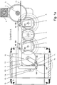
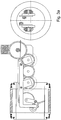
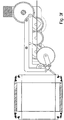
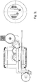
- FIGS. 1a . 1b and 1c show the needle winding system, which in the FIGS. 1a and 1b is disposed on a groove of an inner rotor stator 18.
- the wrapping arm 1 is brought up to the stator 18 for winding and the wire is fixed to one of the end sides of the stator 18. Subsequently, the winding head is moved into the center of the stator 18, wherein the wire outlet nozzle 16 is based on the coupling rods A9 and B10 in a 90 ° position.
- the wire outlet nozzle is arranged in a pivoting block 9, the direct feed of the wire to the wire outlet nozzle by means of a guide roller 13 and a guide roller 15.
- Both the guide roller 15 and the guide roller 13 are a holder of the guide roller 14 and a holder of the guide roller 13th mounted on the pivoting block with the axes of rotation A3 and B3.
- the pivoting block 9 is arranged on the circumference of a virtual circle whose center is defined by the tip M3 of the wire outlet nozzle 16. In this way position accurate pivotal movements of the winding head of the needle winding system can be performed, which is required for a precise winding along the narrow grooves.
- the pivoting block is arranged at the front end of the bent in the head region at right angles coupling rods A9 and B10.
- the coupling rods A and B 9, 10 are driven by a parallelogram each via synchronized adjusting wheels 4 and 7, front wheel 7 and behind the thumbwheel 4, and an intermediate 6 analogous to a steam locomotive and can initiate the pivotal movements of the swing block 9 in this way.
- the adjusting wheels 4, 7 are each connected to articulation arms 5, 8 with the coupling rods A and B 9, 10.
- the parallelogram guidance results from the correspondingly arranged pivot bearings A1, M1, A2, M2 or B1, M1, B2, M2.
- the drive by a servomotor is transmitted via synchronizing wheels 3 with adjusting shaft 2 to the rear adjusting wheels 4.
- the stator 18 has at its two end faces in the illustrated embodiment, recordings for three phases to be wound, for example, U, V and W, wherein the recordings in the FIG. 1a already have wire bundles for better illustration.
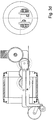
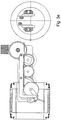
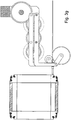
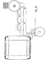
- FIGS. 2a . 2 B and 2c show the same embodiment of the needle winding system when winding a rotor 18a.
- Like reference numerals designate like parts.
- FIGS. 3a . 3b . 3c . 3d . 3e . 3f . 3g . 3h . 3i and 3y the winding process should be illustrated.
- a winding support an internal rotor stator is shown as an example. Basically, according to the method stators how rotors are wound for internal rotor electric motors and external rotor electric motors.
- FIG. 3a is wound inside along a groove of the stator.
- the wire was preferably already fixed to one of the front sides of the stator for this purpose.
- the wire exit nozzle moves further inward along the groove of the stator and reaches the first end, which in FIG. 3b is shown.
- the pivoting block now performs a pivoting movement and brings the wire outlet nozzle in a 180 ° position with respect to the groove in which was driven down in advance.
- the wire outlet nozzle will now continue until in 3d figure shown position.
- the wire exit nozzle has reached the receptacle for the first phase U and can lay the wire in the receptacle, while the stator is rotated according to the set winding step.
- the wire outlet nozzle is again guided over the end face into the groove following the set winding step and moved along it. This condition is in FIG. 3e shown.
- the wire exit nozzle is guided along the groove until the state of movement of the FIG. 3f is reached and the wire exit nozzle at the second end face in transition to the representation of FIG. 3g is panned again.
- the wire exit nozzle will continue until in FIG. 3h shown state moves.
- the wire exit nozzle has the receptacle for the phase U at the reaches the second end face, the stator can now be rotated again according to the predetermined winding step, then leaves the wire outlet nozzle again recording. It is important that the first receptacle is arranged on the end faces of the stator so that the wire supplied to this receptacle does not prematurely cover the remaining slots and the receptacles provided for further phases already in the first winding step.
- phase U wire When the phase U wire has been fully wound, the next phase V coil is wound. Exemplary is in FIG. 3i shown when the wire exit nozzle has reached the intended for phase V recording on the first end face of the stator and the stator can be rotated according to the set winding step.
- the second receptacle on the end faces of the stator must also be arranged so that the phase V wire bundle in the receptacle, the grooves and the receptacles of the phase W are not blocked.
- the winding for the last phase W can now be done in the remaining free grooves, wherein at the end faces of the stator, the wire bundles are stored in the appropriate recordings. Since the phase W is the last phase to be wound, the receptacles for this last phase are usually located at the ends of the stator just above the grooves, so that the grooves are covered. The winding in the receptacle on the first end face of the stator is in FIG. 3j shown.
- FIG. 4a, 4b, 4c and 4d exemplified a circuit diagram, according to which a stator or a rotor can be wound according to the invention.
- the winding step is in this case 1: 6, wherein other winding steps, such as 1: 4, for the winding of the winding carrier of the invention with the needle winding system according to the invention by the method according to the invention are conceivable solely by a software change of the machine program.
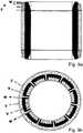
- FIGS. 5a and 5b show the laminated core of an inner rotor stator in longitudinal section and in cross section, wherein in the interior of the cylinder grooves are arranged, which are each open to the inside.
- FIGS. 5a and 5b is the stator of FIGS. 5a and 5b represented analogously with a front side insulation.
- the receptacles arranged further outwards can be covered with wire bundles, without obscuring or blocking the comparatively more central last pickup at the end faces.
- FIGS. 7a and 7b show the stator of the Figures 6a and 6b , which was now wound with a wire bundle of the phase U in a first winding.
- FIGS. 8a and 8b show the stator of the FIGS. 7a and 7b which was now wound with a phase V wire bundle in a second winding.
- the new winding is shown in black, the existing winding is shown hatched.
- FIGS. 9a and 9b show the stator of the FIGS. 8a and 8b which has now been wound with a wire bundle of phase W in a third winding.
- the added winding is shown in black, while the already existing windings are shown hatched.
- FIGS 10a and 10b show the fully wound with the phases U, V and W Inneumbler stator.
Abstract
Description
- Die Erfindung betrifft ein Nadelwickelsystem für zu bewickelnde Wicklungsträger nach dem Oberbegriff des Anspruchs 1, ein Verfahren zum Bewickeln von Wicklungsträgern nach Anspruch 4, einen Innenläufer-Stator nach dem Oberbegriff des Anspruchs 10, einen Außenläufer-Stator nach dem Oberbegriff des Anspruchs 12 und einen Wicklungsträger für Elektromotoren mit verteilter Wicklung nach dem Oberbegriff des Anspruchs 14.
- Nach dem Stand der Technik werden Statoren mit verteilter Wicklung nach einem Ein-ziehverfahren mit einer Bewicklung versehen, wobei die Wicklungen zunächst auf Feldspulen auf einer Maschine erzeugt werden, um daran anschließend die Wicklungen von den Feldspulen abzunehmen und als Ganzes in den zu bewickelnden Stator hineinzuziehen.
- Nach dem Einziehverfahren hergestellte Statoren weisen mehrere Nachteile auf. Zunächst sind die Wickelköpfe sehr aufwendig nachzubearbeiten, insbesondere das Verschalten der Anschlussdrähte ist maschinell aufwendig oder muss von vornherein manuell durchgeführt werden. Die Einziehtechnik benötigt aufgrund der großen Drahtwulste in den Wickelköpfen eine größere Drahtlänge als dies bei anderen Wickeltechniken der Fall wäre, wodurch der Materialaufwand steigt und die Länge der zu konstruierenden Elektromotoren zunimmt. Darüber hinaus benötigt die Einziehtechnik oft spezielles Werkzeug und ist damit unflexibel und nur für eine geringe Anzahl an verschiedenen Statortypen geeignet. Ferner sind die Drahtlitzen schwierig zu kontaktieren, da oft Litzen mit Ersatzquerschnitten verwendet werden. Außerdem sind die Phasenstränge im Wickelkopfbereich schwer gegeneinander zu isolieren und überstehende Wickelköpfe müssen in vielen Fällen geformt oder sogar gepresst werden, um den Stator im vorgesehenen Motorgehäuse unterbringen zu können. Da sich Windungen in den umfangreichen Wickelköpfen lösen können, muss oft eine Verklebung mit Harzen oder anderen Klebemitteln oder ein Abbindeverfahren erfolgen, was den Umfang der Wickelköpfe zusätzlich vergrößert.
- Nach dem Stand der Technik ist u.a. die
EP 1 759 446 B1 bekannt, die eine Wickelvorrichtung offenbart, bei der eine Wickelnadel in zwei im rechten Winkel zueinander stehenden Arbeitspositionen einstellbar ist. - Eine derartige Wickelvorrichtung kann Statoren für Innenläufer-Elektromotoren, die nach innen offene Nuten aufweisen, nur mit einer konzentrierten Wicklung bewickeln, da die Drahtbündel sonst noch freie Nuten beim Bewickeln mit verdecken und somit für weitere Polungen blockieren würde.
- Aufgabe der Erfindung ist es deshalb ein Nadelwickelsystem zu entwickeln, welches eine verteilte Wicklung auch in nach innen geöffnete Nuten eines Wickelträgers ermöglicht, ohne dass benachbarte, noch freizuhaltende Nuten verdeckt werden. Aufgabe der Erfindung ist außerdem, ein Verfahren bereitzustellen, nach dem Wicklungsträger, wie Statoren oder Rotoren, mit nach innen offenen Nuten mit verteilter Wicklung versehen werden können. Darüber hinaus ist es Aufgabe der Erfindung, Wicklungsträger und insbesondere Innenläufer-Statoren und Außenläufer-Rotoren bereitzustellen, die mit verteilter Wicklung bewickelbar sind, d.h. die bei einem Bewicklungsschritt die noch nicht zu bewickelnden Nuten freihalten, so dass diese für nachfolgende Bewicklungsschritte bewickelbar sind.
- Gelöst wird diese Aufgabe durch eine Nadelwickelsystem für zu bewickelnde Wicklungsträger gemäß des Oberbegriffs von Anspruch 1 durch die Merkmale des kennzeichnenden Teils des Anspruchs 1, durch ein Verfahren zum Bewickeln von Wicklungsträgern mit verteilter Wicklung nach Anspruch 4, durch einen Innenläufer-Stator nach Anspruch 10, durch einen Au-βenläufer-Stator nach Anspruch 12 und einen Wicklungsträger nach Anspruch 14.
- Anspruch 1 sieht ein Nadelwickelsystem für zu bewickelnde Wicklungsträger, insbesondere Statoren, Anker oder Rotoren von Elektromotoren mit verteilter Wicklung vor, das einen translatorisch in Längsrichtung und/oder in Querrichtung beweglichen Wickelkopf, ein Nadelträgersystem mit einer Drahtaustrittsdüse und eine Drahtführung umfasst, wobei das Nadelträgersystem über eine Parallelogrammführung von einer Antriebseinheit antreibbar ist und wobei ein Schwenkklotz des Nadelträgersystems entlang eines vollen virtuellen Kreisumfangs schwenkbeweglich ist und die Drahtaustrittsdüse des Nadelträgersystems stets ins Zentrum des virtuellen Kreises gerichtet ist und somit einen virtuellen Schwenkpunkt definiert.
- Das Nadelwickelsystem nach Anspruch 1 ermöglicht eine Verkürzung des Wickelkopfes. Mit dem Nadelwickelsystem können Statoren und Rotoren einfach mit nur einer Maschine fertiggestellt werden. Das Nadelwickelsystem erlaubt im Vergleich zum Ein-ziehverfahren die Verarbeitung von dickeren Ersatzquerschnitten, wodurch die Möglichkeit von Fehlern beim Kontaktierverfahren verringert wird. Für mit dem Nadelwickelsystem hergestellte Statoren und Rotoren wird weniger Material, wie beispielsweise Kupferlackdraht benötigt, da große Wulste an den Wickelköpfen vermieden werden. Des Weiteren kann ein Abbinden oder Verkleben sowie ein Formen oder Pressen der Wickelköpfe unterbleiben. Als weiterer Vorteil sind die Phasen einfacher durch entsprechend gestaltete Kunststoffendscheiben isolierbar. Darüber hinaus ist das Nadelwickelsystem sehr flexibel einsetzbar und ermöglicht mehrere Fertigungsverfahren, da die Verwendung von anders gestalteten Bauteilen, lediglich durch Änderungen der Einstellungen im Steuerprogramm und der Änderung einer Spulenträgeraufnahme möglich ist. Durch die Direktbewicklung der Wicklungsträger sind außerdem weniger Verschaltungsdrähte als bei Anwendung eines Einziehverfahrens erforderlich. Als weiterer Vorteil besteht die Möglichkeit elektrische Anschlusspunkte konstruktiv an Kunststoffendkappen vorzusehen.
- Vorteilhafte Ausgestaltungen und Weiterbildungen des Nadelwickelsystems für zu bewickelnde Wicklungsträger ergeben sich aus den Unteransprüchen 2 und 3.
- Demnach ist vorteilhaft, dass die Parallelogrammführung über Stellräder, vorzugsweise über Zahnräder, synchronisiert ist.
- Die Synchronisierung der Parallelogrammführung über Stellräder ermöglicht es, den Wickelkopf des Nadelwickelsystems schlank zu gestalten und trotzdem volle Funktionalität im Hinblick auf die Schwenkbewegungen zu gewährleisten. Durch die schlanke Formgebung sind auch Wicklungsträger mit kleinen Durchmessern mit dem Nadelträgersystem bewickelbar.
- Vorteilhaft ist auch, dass die Drahtführung vor der Drahtaustrittsdüse eine jeweils mit einem Halter am Schwenkklotz gelagerte Führungsrolle und Umlenkrolle aufweist.
- Führungsrolle und Umlenkrolle ermöglichen eine sichere Drahtführung und große Biegungen des zuzuführenden Drahtes auch bei sehr verschwenkter Drahtaustrittsdüse.
- Anspruch 4 sieht ein Verfahren zum Bewickeln von Wicklungsträgern mit verteilter Wicklung, vorzugsweise von Statoren oder Rotoren, mit einer Nadelwickelvorrichtung, insbesondere nach den Ansprüchen 1 bis 3, vor, welches die folgenden Schritte umfasst:
- A. - Bewickeln des Wicklungsträgers mit einem Draht einer ersten Polung, wobei der Draht vom Nadelwickelsystem entlang der für einen Wickelschritt vorgesehenen Nuten geführt und an den Stirnseiten des Wicklungsträgers in eine erste Aufnahme eingebracht wird, und wobei in den Nuten und in der ersten Aufnahme ein Drahtbündel einer Polung gebildet wird, welches weitere Nuten und Aufnahmen für weitere Drahtbündel entsprechend dem vorgesehenen Wickelschritt nicht verdeckt,
- B. - gegebenenfalls Bewickeln des Wicklungsträgers mit weiteren Drähten entsprechend dem Schritt A in noch freie Nuten und Aufnahmen nach dem vorgesehenen Wickelschritt, wobei beim Bewickeln mit dem letzten Drahtbündel die Aufnahmen an den Stirnseiten so angeordnet sein können, dass die Nuten nach dem Bewickeln mit dem letzten Drahtbündel verdeckt sind.
- Das Verfahren nach Anspruch 4 hat gegenüber herkömmlichen Verfahren, wie dem Einziehverfahren, den Vorteil, dass die bewickelten Statoren oder Rotoren keine großen Drahtwulste an den Stirnseiten aufweisen, die geformt und/oder verklebt werden müssten. Durch die damit insgesamt kompakteren Statoren und Rotoren sind kürzere Elektromotoren realisierbar. Außerdem sind die elektrischen Anschlusspunkte konstruktiv besser zugänglich und die einzelnen Phasen besser zu isolieren. Das Wickelverfahren nach Anspruch 4 verbraucht darüber hinaus vergleichsweise weniger teuren Kupferdraht als die Einziehverfahren. Außerdem können dickere Einzeldrähte verarbeitet werden.
- Vorteilhafte Ausgestaltungen und Weiterbildungen des Verfahrens zum Bewickeln von Wicklungsträgern mit verteilter Wicklung, vorzugsweise von Statoren oder Rotoren, mit einer Nadelwickelvorrichtung, insbesondere nach den Ansprüchen 1 bis 3, ergeben sich aus den Unteransprüchen 5 bis 9.
- Demgemäß ist vorteilhaft, dass die Statoren Innenläufer-Stato-ren und die Rotoren Außenläufer-Rotoren sind, die jeweils vorzugsweise zylindrisch sind.
- Zylindrische Innenläufer-Statoren und Außenläufer-Rotoren sind aufgrund ihrer geometrischen Formgebung besonders effizient nach dem Wicklungsverfahren des Anspruchs 4 zu bewickeln.
- Vorteilhaft ist auch, dass die Statoren oder Rotoren jeweils nach innen geöffnete Nuten aufweisen.
- Besonders bei nach innen geöffneten Nuten der Wicklungsträger werden die Vorteile des Wickelverfahrens nach Anspruch 4 sichtbar, da der kleinere Umfang an der Innenseite des Wicklungsträgers zu einem schlechteren Zugang zu den einzelnen Nuten führt.
- Vorteilhaft ist außerdem, dass der zu bewickelnde Wicklungsträger für das Bewickeln radial beweglich angeordnet ist und vorzugsweise durch einen Servomotor angetrieben wird.
- Durch Rotieren des Wicklungsträgers werden die erforderlichen Bewegungen des Nadelwickelsystems minimiert und damit die Bewicklungszeit verkürzt.
- Vorteilhaft ist ferner, dass der Wicklungsträger zum Verschalten der Spulen an den Aufnahmen der Stirnseiten radial bewegt wird.
- Durch Rotieren des Wicklungsträgers kann die für das Verschalten erforderliche Zeit verringert werden, außerdem werden die notwendigen Bewegungen des Nadelträgersystems reduziert.
- Vorteilhaft ist darüber hinaus, dass als weiterer Schritt das Befestigen des Drahtes an einer der Stirnseiten des Wicklungsträgers für alle erforderlichen Anschlusspunkte einer Stern-Dreiecks-Schaltung vorgesehen ist.
- Durch diesen Verfahrensschritt werden die Anschlusspunkte gleich mit generiert und insbesondere müssen die jeweiligen Drahtenden nicht später isoliert werden.
- Anspruch 10 sieht einen Innenläufer-Stator, insbesondere zum Bewickeln nach dem Verfahren nach den Ansprüchen 4 bis 9, vor, der ein vorzugsweise zylindrisch geformtes Blechpaket und eine Isolierung umfasst, wobei der Innenläufer-Stator nach innen offene Nuten aufweist, wobei der Innenläufer-Stator Stirnseiten und einen Zylindermantel aufweist, wobei der Innenläufer-Stator an den Stirnseiten mindestens zwei getrennte Aufnahmen für unterschiedlich gepolte Drahtbündel aufweist und wobei mindestens eine Aufnahme für ein Drahtbündel außerhalb des Öffnungsbereichs der Nuten angeordnet und durch Wickeln des Drahtes belegbar ist, ohne dabei weitere Aufnahmen für Drahtbündel anderer Spulen zu blockieren.
- Der Innenläufer-Stator nach Anspruch 10 hat den Vorteil, dass eine einfachere Phasenisolation durch entsprechend zu gestaltende Kunststoffendscheiben erfolgen kann und die Wickelköpfe des Stators nicht geformt, abgebunden oder geklebt werden müssen. Der Materialeinsatz an Kupferdraht wird zudem niedrig gehalten, wobei auch dickere Kupferdrähte verwendbar sind.
- Eine vorteilhafte Weiterbildung des Innenläufer-Stators nach Anspruch 10 ergibt sich aus Unteranspruch 11.
- Demnach ist vorteilhaft, dass die Aufnahmen an den Stirnseiten als bogenförmige Wickelköpfe ausgeführt sind.
- Die bogenförmigen Wickelköpfe erfordern aufgrund der Aufnahmen des Stators nur sehr wenig zusätzlichen Raum, so dass der Stator in kompakte Motoren eingesetzt werden kann.
- Anspruch 12 sieht einen Außenläufer-Rotor, insbesondere zum Bewickeln nach dem Verfahren nach den Ansprüchen 4 bis 9, vor, der ein vorzugsweise zylindrisch geformtes Blechpaket und eine Isolierung umfasst, wobei der Außerläufer-Rotor nach innen offene Nuten aufweist und wobei der Außenläufer-Rotor Stirnseiten und einen Zylindermantel aufweist, wobei der Außerläufer-Rotor an den Stirnseiten mindestens zwei getrennte Aufnahmen für unterschiedlich gepolte Drahtbündel aufweist, wobei mindestens eine Aufnahme für ein Drahtbündel außerhalb des Öffnungsbereichs der Nuten angeordnet und durch Wickeln des Drahtes belegbar ist, ohne dabei weitere Aufnahmen für Drahtbündel anderer Spulen zu blockieren.
- Für den Außenläufer-Rotor nach Anspruch 12 ergeben sich die gleichen Vorteile wie für den Innenläufer-Stator nach Anspruch 10.
- Eine vorteilhafte Weiterbildung des Außenläufer-Rotors nach Anspruch 10 ergibt sich aus Unteranspruch 13.
- So ist es vorteilhaft, dass die Aufnahmen an den Stirnseiten als bogenförmige Wickelköpfe ausgeführt sind.
- Die Vorteile eines Außenläufer-Rotors nach Anspruch 13 entsprechen den Vorteilen des Innenläufer-Stators nach Anspruch 11.
- Nach Anspruch 14 ist ein Wicklungsträger für Elektromotoren mit verteilter Wicklung, insbesondere nach dem Verfahren nach den Ansprüchen 4 bis 9, vorgesehen, der ein vorzugsweise zylindrisch geformtes Blechpaket und eine Isolierung umfasst, wobei der Wicklungsträger nach innen offene Nuten aufweist und wobei der Wicklungsträger Stirnseiten und einen Zylindermantel aufweist, wobei der Wicklungsträger an den Stirnseiten mindestens zwei getrennte Aufnahmen für unterschiedlich gepolte Drahtbündel aufweist und wobei mindestens eine Aufnahme für ein Drahtbündel außerhalb des Öffnungsbereichs der Nuten angeordnet und durch Wickeln des Drahtes belegbar ist, ohne dabei weitere Aufnahmen für Drahtbündel anderer Spulen zu blockieren.
- Für den Wicklungsträger nach Anspruch 14 ergeben sich die gleichen Vorteile wie für den Innenläufer-Stator nach Anspruch 10.
- Vorteilhafte Ausgestaltungen und Weiterbildungen des Wicklungsträgers für Elektromotoren mit verteilter Wicklung ergeben sich aus den Unteransprüchen 15 und 16.
- Demnach ist es vorteilhaft, dass die Aufnahmen an den Stirnseiten als bogenförmige Wickelköpfe ausgeführt sind.
- Die Vorteile eines Wicklungsträgers nach Anspruch 15 entsprechen den Vorteilen des Innenläufer-Stators nach Anspruch 11.
- Außerdem ist es vorteilhaft, dass der Wicklungsträger als Stator eines Innenläufer-Elektromotors oder als Rotor eines Außenläufer-Elektromotors angeordnet ist.
- Die Wicklungsträger nach Anspruch 16 machen sowohl Innenläufer-Statoren als auch Außenläufer-Rotoren verfügbar, deren Bewicklung vergleichsweise wenig Kupferdraht erfordert und deren Wickelköpfe kaum zusätzlichen Platz beanspruchen.
- Weitere Eigenschaften, Merkmale und Vorteile der Erfindung werden nachfolgend anhand von Figuren von bevorzugten Ausführungsformen des Nadelwickelsystems nach Anspruch 1, des Verfahrens zum Bewickeln von Wicklungsträgern mit verteilter Wicklung nach Anspruch 4, des Innenläufer-Stators nach Anspruch 10, des Außenläufer-Rotors nach Anspruch 12 und des Wicklungsträgers nach Anspruch 14 näher erläutert. Im Einzelnen zeigen
- Figur 1a -
- einen schematischen Längsschnitt entlang der Linie A-A der
Figur 1b des Nadelwickelsystems mit einem zu bewickelnden InnenläuferStator, - Figur 1b -
- einen schematischen Querschnitt des Nadelwickelsystems mit einem zu bewickelnden Innenläufer-Stator,
- Figur 1c -
- eine schematische Draufsicht auf das Nadelsystem mit einem zu bewickelnden Innenläufer-Stator,
- Figur 2a -
- einen schematischen Längsschnitt entlang der Linie A-A der
Figur 1b des Nadelwickelsystems mit einem zu bewickelnden Rotor, - Figur 2b -
- einen schematischen Querschnitt des Nadelwickelsystems mit einem zu bewickelnden Rotor,
- Figur 2c -
- eine schematische Draufsicht auf das Nadelsystem mit einem zu bewickelnden Rotor,
- Figur 3a -
- einen schematischen Längsschnitt des Nadelwickelsystems mit einem zu bewickelnden Innenläufer-Stator beim Bewickeln von innen, entlang der einer Nut,
- Figur 3b -
- einen schematischen Längsschnitt des Nadelwickelsystems mit einem zu bewickelnden Innenläufer-Stator beim Bewickeln, wobei die Drahtaustrittsdüse die erste Stirnseite des Stators erreicht hat,
- Figur 3c -
- einen schematischen Längsschnitt des Nadelwickelsystems mit einem zu bewickelnden Innenläufer-Stator beim Bewickeln, wobei die Drahtaustrittsdüse an der ersten Stirnseite des Stators geschwenkt wurde,
- Figur 3d -
- einen schematischen Längsschnitt des Nadelwickelsystems mit einem zu bewickelnden Innenläufer-Stator beim Bewickeln, wobei die Drahtaustrittsdüse die Aufnahme des Drahtbündels an der ersten Stirnseite für die erste Polung erreicht hat,
- Figur 3e -
- einen schematischen Längsschnitt des Nadelwickelsystems mit einem zu bewickelnden Innenläufer-Stator beim Bewickeln, wobei die Drahtaustrittsdüse nach Rotieren des Stators wieder innen entlang einer weiteren Nut fährt,
- Figur 3f -
- einen schematischen Längsschnitt des Nadelwickelsystems mit einem zu bewickelnden Innenläufer-Stator beim Bewickeln, wobei die Drahtaustrittsdüse die zweite Stirnseite des Stators erreicht hat,
- Figur 3g -
- einen schematischen Längsschnitt des Nadelwickelsystems mit einem zu bewickelnden Innenläufer-Stator beim Bewickeln, wobei die Drahtaustrittsdüse an der zweiten Stirnseite des Stators geschwenkt wurde,
- Figur 3h -
- einen schematischen Längsschnitt des Nadelwickelsystems mit einem zu bewickelnden Innenläufer-Stator beim Bewickeln, wobei die Drahtaustrittsdüse die Aufnahme des Drahtbündels an der zweiten Stirnseite für die erste Polung erreicht hat,
- Figur 3i -
- einen schematischen Längsschnitt des Nadelwickelsystems mit einem zu bewickelnden Innenläufer-Stator beim Bewickeln, wobei die Drahtaustrittsdüse die Aufnahme des Drahtbündels an der ersten Stirnseite für die zweite Polung erreicht hat,
- Figur 3j -
- einen schematischen Längsschnitt des Nadelwickelsystems mit einem zu bewickelnden Innenläufer-Stator beim Bewickeln, wobei die Drahtaustrittsdüse die Aufnahme des Drahtbündels an der ersten Stirnseite für die dritte Polung erreicht hat,
- Figur 4a -
- Schaltschema für die erste Phase U am Wicklungsträger,
- Figur 4b -
- Schaltschema für die zweite Phase V am Wicklungsträger,
- Figur 4c -
- Schaltschema für die dritte Phase W am Wicklungsträger,
- Figur 4d
- Schaltschema für alle Phasen U, V und W am Wicklungsträger,
- Figur 5a -
- einen schematischen Längsschnitt des Blechpakets eines Innenläufer-Stators,
- Figur 5b -
- einen schematischen Querschnitt des Blechpakets eines Innenläufer-Stators,
- Figur 6a -
- einen schematischen Längsschnitt des Innenläufer-Stators mit Stirnseitenisolation,
- Figur 6b -
- einen schematischen Querschnitt des Innenläufer-Stators mit Stirnseitenisolation,
- Figur 7a -
- einen schematischen Längsschnitt des Innenläufer-Stators mit Stirnseitenisolation und einer ersten Wicklung der Phase U,
- Figur 7b -
- einen schematischen Querschnitt des Innenläufer-Stators mit Stirnseitenisolation und einer ersten Wicklung der Phase U,
- Figur 8a -
- einen schematischen Längsschnitt des Innenläufer-Stators mit Stirnseitenisolation und einer zweiten Wicklung der Phase V,
- Figur 8b -
- einen schematischen Querschnitt des Innenläufer-Stators mit Stirnseitenisolation und einer zweiten Wicklung der Phase V,
- Figur 9a -
- einen schematischen Längsschnitt des Innenläufer-Stators mit Stirnseitenisolation und einer dritten Wicklung der Phase W,
- Figur 9b -
- einen schematischen Querschnitt des Innenläufer-Stators mit Stirnseitenisolation und einer dritten Wicklung der Phase W,
- Figur 10a -
- einen schematischen Längsschnitt des vollständig mit den Phasen U, V und W bewickelten Innenläufer-Stators,
- Figur 10b -
- einen schematischen Querschnitt des vollständig mit den Phasen U, V und W bewickelten Innenläufer-Stators.
- Anhand der folgenden Figuren werden Ausführungsformen des Nadelwickelsystems und von Wicklungsträgern mit den Beispielen eines Innenläufer-Stators und eines Außenläufer-Rotors erläutert. Mit Hilfe der Figuren wird darüber hinaus auch eine Ausführungsform des Wicklungsverfahrens beschrieben.
- Die
Figuren 1a ,1b und1c zeigen das Nadelwickelsystem, das in denFiguren 1a und1b an einer Nut eines Innenläufer-Stators 18 angeordnet ist. Der Wickelarm 1 wird für das Bewickeln an den Stator 18 herangefahren und der Draht an einer der Stirnseiten des Stators 18 fixiert. Anschließend wird der Wickelkopf in das Zentrum des Stators 18 bewegt, wobei sich die Drahtaustrittsdüse 16 bezogen auf die Koppelstangen A9 und B10 in einer 90°-Stellung befindet. Die Drahtaustrittsdüse ist in einem Schwenkklotz 9 angeordnet, die unmittelbare Zuführung des Drahtes zur Drahtaustrittsdüse erfolgt mit Hilfe einer Umlenkrolle 13 und einer Führungsrolle 15. Sowohl die Führungsrolle 15 als auch die Umlenkrolle 13 sind über einen Halter der Führungsrolle 14 bzw. einen Halter der Umlenkrolle 13 am Schwenkklotz mit den Drehachsen A3 bzw. B3 gelagert. Bei jeder Schwenkbewegung der Drahtaustrittsdüse 16 ist der Schwenkklotz 9 am Kreisumfang eines virtuellen Kreises angeordnet, dessen Zentrum durch die Spitze M3 der Drahtaustrittsdüse 16 definiert ist. Auf diese Weise können positionsgenaue Schwenkbewegungen des Wickelkopfes des Nadelwickelsystems durchgeführt werden, was für eine präzise Bewicklung entlang der engen Nuten erforderlich ist. - Der Schwenkklotz ist am vorderen Ende der im Kopfbereich im rechten Winkel gebogenen Kopplungsstangen A9 und B10 angeordnet. Die Kopplungsstangen A und B 9, 10 werden mittels einer Parallelogrammführung jeweils über synchronisierte Stellräder 4 und 7, vorderes Stellrad 7 und hinters Stellrad 4, und ein Zwischenrad 6 analog einer Dampflokomotive angetrieben und können auf diese Weise die Schwenkbewegungen des Schwenkklotzes 9 einleiten. Die Stellräder 4, 7 sind jeweils an Anlenkarmen 5, 8 mit den Kopplungsstangen A und B 9, 10 verbunden. Die Parallelogrammführung ergibt sich aus den entsprechend angeordneten Drehlagern A1, M1, A2, M2 bzw. B1, M1, B2, M2. Der Antrieb durch einen Servomotor wird über Gleichlaufräder 3 mit Verstellwelle 2 auf die hinteren Stellräder 4 übertragen.
- Der Stator 18 verfügt an seinen beiden Stirnseiten bei der dargestellten Ausführungsform über Aufnahmen für drei zu bewickelnde Phasen, beispielsweise U, V und W, wobei die Aufnahmen in der
Figur 1a zur besseren Darstellung bereits Drahtbündel aufweisen. - Die
Figuren 2a ,2b und2c zeigen dieselbe Ausführungsform des Nadelwickelsystems beim Bewickeln eines Rotors 18a. Gleiche Bezugszeichen bezeichnen gleiche Teile. - Anhand der
Figuren 3a ,3b ,3c ,3d ,3e ,3f ,3g ,3h ,3i und3j soll das Wickelverfahren veranschaulicht werden. Als Wicklungsträger ist als Beispiel ein Innenläufer-Stator dargestellt. Grundsätzlich können nach dem Verfahren Statoren wie Rotoren für Innenläufer-Elektromotoren und Außenläufer-Elektromotoren bewickelt werden. - In
Figur 3a wird innen entlang einer Nut der Stator bewickelt. Der Draht wurde dafür vorzugsweise bereits zuvor an einer der Stirnseiten des Stators fixiert. Die Drahtaustrittsdüse fährt weiter innen entlang der Nut des Stators und erreicht die erste Stirnseite, was inFigur 3b dargestellt ist. Um den inFigur 3c dargestellten Bewegungszustand zu erreichen, führt der Schwenkklotz nun eine Schwenkbewegung aus und bringt die Drahtaustrittsdüse in eine 180°-Stellung in Bezug auf die Nut, in der vorab entlang gefahren wurde. Die Drahtaustrittsdüse wird nun weiter bis zur inFigur 3d gezeigten Stellung geführt. InFigur 3d hat die Drahtaustrittsdüse die Aufnahme für die erste Phase U erreicht und kann den Draht in der Aufnahme ablegen, dabei wird der Stator entsprechend dem eingestellten Wickelschritt rotiert. - Nach der Rotation des Stators wird die Drahtaustrittsdüse wieder über die Stirnseite hinweg in die entsprechend dem eingestellten Wickelschritt nachfolgende Nut geführt und in dieser entlang gefahren. Dieser Zustand ist in
Figur 3e dargestellt. Die Drahtaustrittsdüse wird entlang der Nut weiter geführt bis der Bewegungszustand derFigur 3f erreicht ist und die Drahtaustrittsdüse an der zweiten Stirnseite im Übergang zur Darstellung derFigur 3g wieder geschwenkt wird. Die Drahtaustrittsdüse wird weiter bis zum inFigur 3h dargestellten Zustand bewegt. InFigur 3h hat die Drahtaustrittsdüse die Aufnahme für die Phase U an der zweiten Stirnseite erreicht, der Stator kann nun wieder entsprechend dem vorgegebenen Wickelschritt rotiert werden, anschließend verlässt die Drahtaustrittsdüse wieder die Aufnahme. Wichtig ist, dass die erste Aufnahme an den Stirnseiten des Stators so angeordnet ist, dass der dieser Aufnahme zugeführte Draht die freigebliebenen Nuten und die für weitere Phasen vorgesehenen Aufnahmen nicht vorzeitig bereits im ersten Wickelschritt verdeckt. - Wenn der Draht der Phase U vollständig gewickelt wurde, wird die nächste Teilspule der Phase V gewickelt. Exemplarisch ist in
Figur 3i dargestellt, wenn die Drahtaustrittsdüse die für Phase V vorgesehene Aufnahme an der ersten Stirnseite des Stators erreicht hat und der Stator entsprechend dem eingestellten Wickelschritt rotiert werden kann. Auch die zweite Aufnahme an den Stirnseiten des Stators muss so angeordnet sein, dass das Drahtbündel der Phase V in der Aufnahme, die Nuten und die Aufnahmen der Phase W nicht blockiert. - Die Bewicklung für die letzte Phase W kann nun in die verbliebenen freien Nuten erfolgen, wobei an den Stirnseiten des Stators die Drahtbündel in den entsprechenden Aufnahmen abgelegt werden. Da die Phase W die letzte zu wickelnde Phase ist, sind die Aufnahmen für diese letzte Phase in der Regel an den Stirnseiten des Stators unmittelbar über den Nuten angeordnet, so dass die Nuten verdeckt werden. Die Bewicklung in die Aufnahme an der ersten Stirnseite des Stators ist in
Figur 3j dargestellt. - In den
Figuren 4a, 4b, 4c und 4d ist exemplarisch ein Schaltschema dargestellt, nach dem ein Stator oder ein Rotor nach der Erfindung bewickelbar ist. Der Wickelschritt ist in diesem Fall 1:6, wobei auch andere Wickelschritte, wie 1:4, für die Bewicklung der Wicklungsträger der Erfindung mit dem Nadelwickelsystem nach der Erfindung nach dem Verfahren nach der Erfindung allein durch eine Softwareänderung des Maschinenprogramms denkbar sind. - Die
Figuren 5a und 5b zeigen das Blechpaket eines Innenläufer-Stators im Längsschnitt und im Querschnitt, wobei im Inneren des Zylinders Nuten angeordnet sind, die jeweils nach innen geöffnet sind. - In den
Figuren 6a und 6b ist der Stator derFiguren 5a und 5b analog mit einer Stirnseitenisolation dargestellt. Anhand dieser Figuren wird ersichtlich, dass die weiter außen angeordneten Aufnahmen mit Drahtbündeln belegt werden können, ohne die vergleichsweise zentralere letze Aufnahme an den Stirnseiten zu verdecken oder zu blockieren. - Die
Figuren 7a und 7b zeigen den Stator derFiguren 6a und 6b , der nun mit einem Drahtbündel der Phase U in einer ersten Wicklung bewickelt wurde. - Die
Figuren 8a und 8b zeigen den Stator derFiguren 7a und 7b , der nun mit einem Drahtbündel der Phase V in einer zweiten Wicklung bewickelt wurde. Die neue Wicklung ist schwarz eingezeichnet, die bereits vorhandene Wicklung ist schraffiert dargestellt. - Die
Figuren 9a und 9b zeigen den Stator derFiguren 8a und 8b , der nun mit einem Drahtbündel der Phase W in einer dritten Wicklung bewickelt wurde. Die hinzugekommene Wicklung ist schwarz eingezeichnet, während die bereits vorhandenen Wicklungen schraffiert dargestellt sind. - Die
Figuren 10a und 10b zeigen den mit den Phasen U, V und W vollständig bewickelten Inneläufer-Stator.
Claims (16)
- Nadelwickelsystem für zu bewickelnde Wicklungsträger (18, 18a), insbesondere Statoren (18), Anker oder Rotoren (18a) von Elektromotoren mit verteilter Wicklung, einen translatorisch in Längsrichtung und/oder in Querrichtung beweglichen Wickelkopf, ein Nadelträgersystem mit einer Drahtaustrittsdüse (16) und eine Drahtführung (17) umfassend, wobei das Nadelträgersystem über eine Parallelogrammführung von einer Antriebseinheit antreibbar ist,
dadurch gekennzeichnet,
dass ein Schwenkklotz (11) des Nadelträgersystems entlang eines vollen virtuellen Kreisumfangs schwenkbeweglich ist und die Drahtaustrittsdüse (16) des Nadelträgersystems stets ins Zentrum des virtuellen Kreises gerichtet ist und somit einen virtuellen Schwenkpunkt definiert. - Nadelwickelsystem nach Anspruch 1,
dadurch gekennzeichnet,
dass die Parallelogrammführung über Stellräder (4, 7), vorzugsweise über Zahnräder synchronisiert ist. - Nadelwickelsystem nach Anspruch 1 oder 2,
dadurch gekennzeichnet,
dass die Drahtführung vor der Drahtaustrittsdüse (16) eine jeweils mit einem Halter am Schwenkklotz (11) gelagerte Führungsrolle (15) und Umlenkrolle (13) aufweist. - Verfahren zum Bewickeln von Wicklungsträgern (18, 18a) mit verteilter Wicklung, vorzugsweise von Statoren (18) oder Rotoren (18a), mit einer Nadelwickelvorrichtung, insbesondere nach den Ansprüchen 1 bis 3, die folgenden Schritte umfassend:A. Bewickeln des Wicklungsträgers (18, 18a) mit einem Draht einer ersten Polung, wobei der Draht vom Nadelwickelsystem entlang der für einen Wickelschritt vorgesehenen Nuten geführt und an den Stirnseiten des Wicklungsträgers (18, 18a) in eine erste Aufnahme eingebracht wird, und wobei in den Nuten und in der ersten Aufnahme ein Drahtbündel einer Polung gebildet wird, welches weitere Nuten und Aufnahmen für weitere Drahtbündel entsprechend dem vorgesehenen Wickelschritt nicht verdeckt,B. gegebenenfalls Bewickeln des Wicklungsträgers (18, 18a) mit weiteren Drähten entsprechend dem Schritt A in noch freie Nuten und Aufnahmen nach dem vorgesehenen Wickelschritt, wobei beim Bewickeln mit dem letzten Drahtbündel die Aufnahmen an den Stirnseiten so angeordnet sein können, dass die Nuten nach dem Bewickeln mit dem letzten Drahtbündel verdeckt sind.
- Verfahren zum Bewickeln von Wicklungsträgern mit verteilter Wicklung nach Anspruch 4,
dadurch gekennzeichnet,
dass die Statoren (18) Innenläufer-Statoren (18) und die Rotoren (18a) Außenläufer-Rotoren sind, die jeweils vorzugsweise zylindrisch sind. - Verfahren zum Bewickeln von Wicklungsträgern mit verteilter Wicklung nach Anspruch 4 oder 5,
dadurch gekennzeichnet,
dass die Statoren (18) oder Rotoren (18a) jeweils nach innen geöffnete Nuten aufweisen. - Verfahren zum Bewickeln von Wicklungsträgern mit verteilter Wicklung nach einem der vorangegangenen Ansprüche,
dadurch gekennzeichnet,
dass der zu bewickelnde Wicklungsträger (18, 18a) für das Bewickeln radial beweglich angeordnet ist und vorzugsweise durch einen Servomotor angetrieben wird. - Verfahren zum Bewickeln von Wicklungsträgern mit verteilter Wicklung nach Anspruch 7,
dadurch gekennzeichnet,
dass der Wicklungsträger (18, 18a) zum Verschalten der Spulen an den Aufnahmen der Stirnseiten radial bewegt wird. - Verfahren zum Bewickeln von Wicklungsträgern mit verteilter Wicklung nach einem der vorangegangenen Ansprüche,
dadurch gekennzeichnet,
dass als weiterer Schritt das Befestigen des Drahtes an einer der Stirnseiten des Wicklungsträgers (18, 18a) für alle erforderlichen Anschlusspunkte einer Stern-Dreiecks-Schaltung vorgesehen ist. - Innenläufer-Stator (18), insbesondere zum Bewickeln nach dem Verfahren nach den Ansprüchen 4 bis 9, ein vorzugsweise zylindrisch geformtes Blechpaket und eine Isolierung umfassend, wobei der Innenläufer-Stator nach innen offene Nuten aufweist und wobei der Innenläufer-Stator Stirnseiten und einen Zylindermantel aufweist,
dadurch gekennzeichnet,
dass der Innenläufer-Stator (18) an den Stirnseiten mindestens zwei getrennte Aufnahmen für unterschiedlich gepolte Drahtbündel aufweist, wobei mindestens eine Aufnahme für ein Drahtbündel außerhalb des Öffnungsbereichs der Nuten angeordnet und durch Wickeln des Drahtes belegbar ist, ohne dabei weitere Aufnahmen für Drahtbündel anderer Spulen zu blockieren. - Innenläufer-Stator nach Anspruch 10,
dadurch gekennzeichnet,
dass die Aufnahmen an den Stirnseiten als bogenförmige Wickelköpfe ausgeführt sind. - Außenläufer-Rotor, insbesondere zum Bewickeln nach dem Verfahren nach den Ansprüchen 4 bis 9, ein vorzugsweise zylindrisch geformtes Blechpaket und eine Isolierung umfassend, wobei der Außerläufer-Rotor nach innen offene Nuten aufweist und wobei der Außenläufer-Rotor Stirnseiten und einen Zylindermantel aufweist,
dadurch gekennzeichnet, dass der Außerläufer-Rotor an den Stirnseiten mindestens zwei getrennte Aufnahmen für unterschiedlich gepolte Drahtbündel aufweist, wobei mindestens eine Aufnahme für ein Drahtbündel außerhalb des Öffnungsbereichs der Nuten angeordnet und durch Wickeln des Drahtes belegbar ist, ohne dabei weitere Aufnahmen für Drahtbündel anderer Spulen zu blockieren. - Außenläufer-Rotor nach Anspruch 12,
dadurch gekennzeichnet,
dass die Aufnahmen an den Stirnseiten als bogenförmige Wickelköpfe ausgeführt sind. - Wicklungsträger (18, 18a) für Elektromotoren mit verteilter Wicklung, insbesondere nach dem Verfahren nach den Ansprüchen 4 bis 9, ein vorzugsweise zylindrisch geformtes Blechpaket und eine Isolierung umfassend, wobei der Wicklungsträger nach innen offene Nuten aufweist und wobei der Wicklungsträger Stirnseiten und einen Zylindermantel aufweist,
dadurch gekennzeichnet,
dass der Wicklungsträger (18, 18a) an den Stirnseiten mindestens zwei getrennte Aufnahmen für unterschiedlich gepolte Drahtbündel aufweist, wobei mindestens eine Aufnahme für ein Drahtbündel außerhalb des Öffnungsbereichs der Nuten angeordnet und durch Wickeln des Drahtes belegbar ist, ohne dabei weitere Aufnahmen für Drahtbündel anderer Spulen zu blockieren. - Wicklungsträger nach Anspruch 14,
dadurch gekennzeichnet,
dass die Aufnahmen an den Stirnseiten als bogenförmige Wickelköpfe ausgeführt sind. - Wicklungsträger nach Anspruch 14 oder 15,
dadurch gekennzeichnet,
dass der Wicklungsträger (18, 18a) als Stator eines Innenläufer-Elektromotors oder als Rotor eines Außenläufer-Elektromotors angeordnet ist.
Priority Applications (3)
| Application Number | Priority Date | Filing Date | Title |
|---|---|---|---|
| PL12000071T PL2477315T3 (pl) | 2011-01-14 | 2012-01-07 | Iglicowy system do nawijania uzwojeń na korpusach, sposób nawijania rozdzielonego uzwojenia na korpusie, stojan urządzenia z wewnętrznym wirnikiem, wirnik urządzenia z zewnętrznym wirnikiem i korpus do silników elektrycznych z rozdzielonym uzwojeniem |
| SI201231450T SI2477315T1 (sl) | 2011-01-14 | 2012-01-07 | Igelni navijalni sistem za nosilec navitja, ki ga je treba naviti, postopek za navijanje nosilca navitja s porazdeljenim navitjem, notranji stator, zunanji rotor in nosilec navitja za elektromotorje s porazdeljenim navitjem |
| HRP20181859TT HRP20181859T1 (hr) | 2011-01-14 | 2018-11-08 | Sustav za namatanje iglom za nosače namota koji se namataju, postupak za namatanje nosača namota s distribuiranim namotom, unutarnjim statorom, vanjskim rotorom i nosačem namota za elektromotore s distribuiranim namotom |
Applications Claiming Priority (1)
| Application Number | Priority Date | Filing Date | Title |
|---|---|---|---|
| DE102011008662A DE102011008662A1 (de) | 2011-01-14 | 2011-01-14 | Nadelwickelsystem für zu bewickelnde Wicklungsträger, Verfahren zum Bewickeln von Wicklungsträgern mit verteilter Wicklung, Innenläufer-Stator, Außenläufer-Rotor und Wicklungsträger für Elektromotorn mit verteilter Wicklung |
Publications (3)
| Publication Number | Publication Date |
|---|---|
| EP2477315A2 true EP2477315A2 (de) | 2012-07-18 |
| EP2477315A3 EP2477315A3 (de) | 2014-06-11 |
| EP2477315B1 EP2477315B1 (de) | 2018-08-22 |
Family
ID=45507390
Family Applications (1)
| Application Number | Title | Priority Date | Filing Date |
|---|---|---|---|
| EP12000071.6A Not-in-force EP2477315B1 (de) | 2011-01-14 | 2012-01-07 | Nadelwickelsystem für zu bewickelnde Wicklungsträger, Verfahren zum Bewickeln von Wicklungsträgern mit verteilter Wicklung, Innenläufer-Stator, Aussenläufer-Rotor und Wicklungsträger für Elektromotoren mit verteilter Wicklung |
Country Status (7)
| Country | Link |
|---|---|
| EP (1) | EP2477315B1 (de) |
| DE (1) | DE102011008662A1 (de) |
| ES (1) | ES2698842T3 (de) |
| HR (1) | HRP20181859T1 (de) |
| PL (1) | PL2477315T3 (de) |
| PT (1) | PT2477315T (de) |
| SI (1) | SI2477315T1 (de) |
Cited By (2)
| Publication number | Priority date | Publication date | Assignee | Title |
|---|---|---|---|---|
| CN109217589A (zh) * | 2018-09-07 | 2019-01-15 | 湘潭远诚机器制造有限公司 | 适用于绕线机的绕线嘴及其生产方法 |
| CN110034645A (zh) * | 2018-01-11 | 2019-07-19 | 奥曼埃斯珀尔坎普有限公司 | 线材排出喷嘴组件 |
Families Citing this family (14)
| Publication number | Priority date | Publication date | Assignee | Title |
|---|---|---|---|---|
| DE102013000370B4 (de) | 2013-01-11 | 2022-06-02 | Audi Ag | Wicklungsträger, insbesondere Stator oder Rotor einer Drehstrom-Elektromaschine und Verfahren zur Herstellung der Wicklung eines Wicklungsträgers |
| DE102014006406B4 (de) | 2014-04-25 | 2018-01-04 | Audi Ag | Vorrichtung und Verfahren zum Bewickeln eines Wicklungsträgers |
| DE102014108208A1 (de) | 2014-06-11 | 2015-12-17 | Friedrich-Alexander-Universität Erlangen-Nürnberg | Drahtführelement, Drahtwickelmaschine mit einem solchen, Verfahren zum Einbringen von Draht und Verfahren zum Zuführen von Draht |
| DE102014009799A1 (de) | 2014-07-03 | 2016-01-07 | Audi Ag | Verfahren und Vorrichtung zur Herstellung einer Elektromaschine |
| DE102015000439A1 (de) * | 2015-01-14 | 2016-07-14 | Audi Ag | Verfahren zum Bewickeln eines Wicklungsträgers |
| DE102015007836A1 (de) * | 2015-03-13 | 2016-09-15 | Audi Ag | Verfahren zum Wickeln einer Spule |
| DE102015013526B3 (de) * | 2015-10-19 | 2017-04-13 | Audi Ag | Vorrichtung und Verfahren zum Bewickeln eines Wicklungsträgers |
| DE102016003802A1 (de) | 2016-03-26 | 2017-09-28 | Audi Ag | Verfahren zum Bewickeln eines Wicklungsträgers |
| DE102016005176A1 (de) | 2016-04-29 | 2017-11-02 | Audi Ag | Verfahren zur Herstellung eines Stators einer elektrischen Maschine |
| DE102016014371A1 (de) * | 2016-12-02 | 2018-06-07 | Audi Ag | Nadelwickelvorrichtung |
| DE102016015238B4 (de) | 2016-12-21 | 2023-03-23 | Audi Ag | Verfahren zum Herstellen einer elektrischen Maschine |
| DE102017223859A1 (de) * | 2017-12-28 | 2019-07-04 | Aumann Espelkamp Gmbh | Wickelmaschine |
| DE102019207865A1 (de) * | 2019-05-29 | 2020-12-03 | Audi Ag | Wickelnadel, Wickelsystem für Drahtwicklungen und Verfahren zur Herstellung einer Drahtwicklung |
| DE102021101678B3 (de) | 2021-01-26 | 2022-05-05 | Schaeffler Technologies AG & Co. KG | Verfahren zum Bewickeln einer sich in einer Längsrichtung erstreckenden Zahnkette |
Citations (1)
| Publication number | Priority date | Publication date | Assignee | Title |
|---|---|---|---|---|
| EP1759446B1 (de) | 2004-06-15 | 2007-10-24 | Aumann GMBH | Wickelvorrichtung |
Family Cites Families (5)
| Publication number | Priority date | Publication date | Assignee | Title |
|---|---|---|---|---|
| JPH09322491A (ja) * | 1996-05-31 | 1997-12-12 | Hitachi Ltd | モータとモータの巻線方法及び巻線装置 |
| DE102005037373B4 (de) * | 2005-08-08 | 2011-05-05 | Siemens Ag | Elektrische Maschine mit einer stirnseitigen Umlenkung von elektrischen Leitern |
| ATE435515T1 (de) * | 2006-12-22 | 2009-07-15 | Ats Wickel Und Montagetechnik | Vorrichtung zum wickeln von statoren von elektromotoren |
| ITTO20080137A1 (it) * | 2008-02-27 | 2009-08-28 | Atop Spa | Apparecchiatura e metodo per avvolgere e terminare nuclei per macchine dinamo elettriche. |
| JP5630890B2 (ja) * | 2009-06-17 | 2014-11-26 | 日特エンジニアリング株式会社 | 線材の巻線方法 |
-
2011
- 2011-01-14 DE DE102011008662A patent/DE102011008662A1/de not_active Withdrawn
-
2012
- 2012-01-07 PT PT12000071T patent/PT2477315T/pt unknown
- 2012-01-07 ES ES12000071T patent/ES2698842T3/es active Active
- 2012-01-07 PL PL12000071T patent/PL2477315T3/pl unknown
- 2012-01-07 SI SI201231450T patent/SI2477315T1/sl unknown
- 2012-01-07 EP EP12000071.6A patent/EP2477315B1/de not_active Not-in-force
-
2018
- 2018-11-08 HR HRP20181859TT patent/HRP20181859T1/hr unknown
Patent Citations (1)
| Publication number | Priority date | Publication date | Assignee | Title |
|---|---|---|---|---|
| EP1759446B1 (de) | 2004-06-15 | 2007-10-24 | Aumann GMBH | Wickelvorrichtung |
Cited By (2)
| Publication number | Priority date | Publication date | Assignee | Title |
|---|---|---|---|---|
| CN110034645A (zh) * | 2018-01-11 | 2019-07-19 | 奥曼埃斯珀尔坎普有限公司 | 线材排出喷嘴组件 |
| CN109217589A (zh) * | 2018-09-07 | 2019-01-15 | 湘潭远诚机器制造有限公司 | 适用于绕线机的绕线嘴及其生产方法 |
Also Published As
| Publication number | Publication date |
|---|---|
| EP2477315A3 (de) | 2014-06-11 |
| PL2477315T3 (pl) | 2019-03-29 |
| PT2477315T (pt) | 2018-12-03 |
| DE102011008662A1 (de) | 2012-07-19 |
| EP2477315B1 (de) | 2018-08-22 |
| SI2477315T1 (sl) | 2018-12-31 |
| HRP20181859T1 (hr) | 2018-12-28 |
| ES2698842T3 (es) | 2019-02-06 |
Similar Documents
| Publication | Publication Date | Title |
|---|---|---|
| EP2477315B1 (de) | Nadelwickelsystem für zu bewickelnde Wicklungsträger, Verfahren zum Bewickeln von Wicklungsträgern mit verteilter Wicklung, Innenläufer-Stator, Aussenläufer-Rotor und Wicklungsträger für Elektromotoren mit verteilter Wicklung | |
| EP3381108B1 (de) | Verfahren zur herstellung einer spulenwicklung zum einlegen in radial offene nuten von statoren oder rotoren von elektromaschinen | |
| DE2746351C2 (de) | ||
| DE102014208082B4 (de) | Verfahren und Vorrichtung zum Herstellen einer Wicklung einer elektrischen Maschine | |
| EP0968563B1 (de) | Verfahren und vorrichtung zum herstellen von wellenwicklungen für elektrische maschinen | |
| EP1905146A1 (de) | Verfahren zum herstellen einer wicklung einer elektrischen maschine | |
| DE102015007836A1 (de) | Verfahren zum Wickeln einer Spule | |
| EP3164933B1 (de) | Verfahren und vorrichtung zur herstellung einer elektromaschine | |
| WO1999013555A1 (de) | Verfahren und vorrichtung zur herstellung einer verteilten wellenwicklung | |
| DE60311955T2 (de) | Apparat und Verfahren zur Herstellung einer Mehrleiter-Wicklung | |
| DE19817304B4 (de) | Verfahren und Vorrichtung zum Herstellen von Wellenwicklungen für elektrische Maschinen | |
| EP2388887A2 (de) | Polkette | |
| EP2269285B1 (de) | Verfahren und vorrichtung zur herstellung einer elektrischen wicklung | |
| DE19757068C1 (de) | Verfahren und Vorrichtung zum Herstellen einer Formspule für eine Erregerwicklung | |
| DE2302192C3 (de) | Verfahren und Vorrichtung zum Wickeln von Statorspulen für elektrische Maschinen | |
| WO2017042013A1 (de) | Verfahren zur herstellung einer formspule für eine elektrische maschine mittels flachdraht | |
| EP1356481B1 (de) | Verfahren zum bewickeln eines ringkerns | |
| DE102013000370B4 (de) | Wicklungsträger, insbesondere Stator oder Rotor einer Drehstrom-Elektromaschine und Verfahren zur Herstellung der Wicklung eines Wicklungsträgers | |
| EP3553927A1 (de) | Wellenwickelvorrichtung und wellenwickelverfahren | |
| DE102013212892A1 (de) | Stator für eine elektrische Maschine | |
| DE102007038429A1 (de) | Verfahren und Vorrichtung zur Herstellung einer elektrischen Wicklung | |
| EP3223410B1 (de) | Verfahren zum bewickeln eines wicklungsträgers | |
| DE2920749C2 (de) | ||
| DE102012219597A1 (de) | Wickelmaschine und Wickelverfahren zum Herstellen einer lokal bandagierten Wicklung und entsprechende elektrische Maschine | |
| WO2024017597A1 (de) | Anordnen einer drahtwicklung in einem magnetisierbaren flussleitkörper eines ständers einer als innenläufer ausgebildeten rotierenden elektrischen maschine |
Legal Events
| Date | Code | Title | Description |
|---|---|---|---|
| PUAI | Public reference made under article 153(3) epc to a published international application that has entered the european phase |
Free format text: ORIGINAL CODE: 0009012 |
|
| AK | Designated contracting states |
Kind code of ref document: A2 Designated state(s): AL AT BE BG CH CY CZ DE DK EE ES FI FR GB GR HR HU IE IS IT LI LT LU LV MC MK MT NL NO PL PT RO RS SE SI SK SM TR |
|
| AX | Request for extension of the european patent |
Extension state: BA ME |
|
| PUAL | Search report despatched |
Free format text: ORIGINAL CODE: 0009013 |
|
| RIC1 | Information provided on ipc code assigned before grant |
Ipc: H02K 15/085 20060101AFI20140429BHEP Ipc: H01F 41/06 20060101ALI20140429BHEP Ipc: H02K 15/09 20060101ALI20140429BHEP |
|
| AK | Designated contracting states |
Kind code of ref document: A3 Designated state(s): AL AT BE BG CH CY CZ DE DK EE ES FI FR GB GR HR HU IE IS IT LI LT LU LV MC MK MT NL NO PL PT RO RS SE SI SK SM TR |
|
| AX | Request for extension of the european patent |
Extension state: BA ME |
|
| 17P | Request for examination filed |
Effective date: 20141125 |
|
| RBV | Designated contracting states (corrected) |
Designated state(s): AL AT BE BG CH CY CZ DE DK EE ES FI FR GB GR HR HU IE IS IT LI LT LU LV MC MK MT NL NO PL PT RO RS SE SI SK SM TR |
|
| 17Q | First examination report despatched |
Effective date: 20160826 |
|
| STAA | Information on the status of an ep patent application or granted ep patent |
Free format text: STATUS: EXAMINATION IS IN PROGRESS |
|
| GRAP | Despatch of communication of intention to grant a patent |
Free format text: ORIGINAL CODE: EPIDOSNIGR1 |
|
| STAA | Information on the status of an ep patent application or granted ep patent |
Free format text: STATUS: GRANT OF PATENT IS INTENDED |
|
| RIC1 | Information provided on ipc code assigned before grant |
Ipc: H01F 41/082 20160101ALI20180119BHEP Ipc: H01F 41/06 20160101ALI20180119BHEP Ipc: H02K 15/09 20060101ALI20180119BHEP Ipc: H02K 15/085 20060101AFI20180119BHEP |
|
| INTG | Intention to grant announced |
Effective date: 20180206 |
|
| GRAS | Grant fee paid |
Free format text: ORIGINAL CODE: EPIDOSNIGR3 |
|
| RAP1 | Party data changed (applicant data changed or rights of an application transferred) |
Owner name: AUMANN ESPELKAMP GMBH |
|
| GRAA | (expected) grant |
Free format text: ORIGINAL CODE: 0009210 |
|
| STAA | Information on the status of an ep patent application or granted ep patent |
Free format text: STATUS: THE PATENT HAS BEEN GRANTED |
|
| AK | Designated contracting states |
Kind code of ref document: B1 Designated state(s): AL AT BE BG CH CY CZ DE DK EE ES FI FR GB GR HR HU IE IS IT LI LT LU LV MC MK MT NL NO PL PT RO RS SE SI SK SM TR |
|
| REG | Reference to a national code |
Ref country code: GB Ref legal event code: FG4D Free format text: NOT ENGLISH |
|
| REG | Reference to a national code |
Ref country code: CH Ref legal event code: EP |
|
| REG | Reference to a national code |
Ref country code: AT Ref legal event code: REF Ref document number: 1033606 Country of ref document: AT Kind code of ref document: T Effective date: 20180915 |
|
| REG | Reference to a national code |
Ref country code: IE Ref legal event code: FG4D Free format text: LANGUAGE OF EP DOCUMENT: GERMAN |
|
| REG | Reference to a national code |
Ref country code: DE Ref legal event code: R096 Ref document number: 502012013267 Country of ref document: DE |
|
| REG | Reference to a national code |
Ref country code: RO Ref legal event code: EPE |
|
| REG | Reference to a national code |
Ref country code: NL Ref legal event code: FP |
|
| REG | Reference to a national code |
Ref country code: HR Ref legal event code: TUEP Ref document number: P20181859 Country of ref document: HR |
|
| REG | Reference to a national code |
Ref country code: PT Ref legal event code: SC4A Ref document number: 2477315 Country of ref document: PT Date of ref document: 20181203 Kind code of ref document: T Free format text: AVAILABILITY OF NATIONAL TRANSLATION Effective date: 20181122 |
|
| REG | Reference to a national code |
Ref country code: HR Ref legal event code: T1PR Ref document number: P20181859 Country of ref document: HR Ref country code: CH Ref legal event code: NV Representative=s name: SCHMAUDER AND PARTNER AG PATENT- UND MARKENANW, CH |
|
| REG | Reference to a national code |
Ref country code: LT Ref legal event code: MG4D |
|
| REG | Reference to a national code |
Ref country code: HR Ref legal event code: ODRP Ref document number: P20181859 Country of ref document: HR Payment date: 20181228 Year of fee payment: 8 |
|
| PG25 | Lapsed in a contracting state [announced via postgrant information from national office to epo] |
Ref country code: LT Free format text: LAPSE BECAUSE OF FAILURE TO SUBMIT A TRANSLATION OF THE DESCRIPTION OR TO PAY THE FEE WITHIN THE PRESCRIBED TIME-LIMIT Effective date: 20180822 Ref country code: RS Free format text: LAPSE BECAUSE OF FAILURE TO SUBMIT A TRANSLATION OF THE DESCRIPTION OR TO PAY THE FEE WITHIN THE PRESCRIBED TIME-LIMIT Effective date: 20180822 Ref country code: SE Free format text: LAPSE BECAUSE OF FAILURE TO SUBMIT A TRANSLATION OF THE DESCRIPTION OR TO PAY THE FEE WITHIN THE PRESCRIBED TIME-LIMIT Effective date: 20180822 Ref country code: FI Free format text: LAPSE BECAUSE OF FAILURE TO SUBMIT A TRANSLATION OF THE DESCRIPTION OR TO PAY THE FEE WITHIN THE PRESCRIBED TIME-LIMIT Effective date: 20180822 Ref country code: NO Free format text: LAPSE BECAUSE OF FAILURE TO SUBMIT A TRANSLATION OF THE DESCRIPTION OR TO PAY THE FEE WITHIN THE PRESCRIBED TIME-LIMIT Effective date: 20181122 Ref country code: GR Free format text: LAPSE BECAUSE OF FAILURE TO SUBMIT A TRANSLATION OF THE DESCRIPTION OR TO PAY THE FEE WITHIN THE PRESCRIBED TIME-LIMIT Effective date: 20181123 Ref country code: IS Free format text: LAPSE BECAUSE OF FAILURE TO SUBMIT A TRANSLATION OF THE DESCRIPTION OR TO PAY THE FEE WITHIN THE PRESCRIBED TIME-LIMIT Effective date: 20181222 |
|
| REG | Reference to a national code |
Ref country code: CH Ref legal event code: PK Free format text: BERICHTIGUNGEN |
|
| REG | Reference to a national code |
Ref country code: ES Ref legal event code: FG2A Ref document number: 2698842 Country of ref document: ES Kind code of ref document: T3 Effective date: 20190206 |
|
| RIC2 | Information provided on ipc code assigned after grant |
Ipc: H01F 41/082 20160101ALI20180119BHEP Ipc: H02K 15/085 20060101AFI20180119BHEP Ipc: H01F 41/06 20160101ALI20180119BHEP Ipc: H02K 15/09 20060101ALI20180119BHEP |
|
| PG25 | Lapsed in a contracting state [announced via postgrant information from national office to epo] |
Ref country code: LV Free format text: LAPSE BECAUSE OF FAILURE TO SUBMIT A TRANSLATION OF THE DESCRIPTION OR TO PAY THE FEE WITHIN THE PRESCRIBED TIME-LIMIT Effective date: 20180822 Ref country code: AL Free format text: LAPSE BECAUSE OF FAILURE TO SUBMIT A TRANSLATION OF THE DESCRIPTION OR TO PAY THE FEE WITHIN THE PRESCRIBED TIME-LIMIT Effective date: 20180822 |
|
| PG25 | Lapsed in a contracting state [announced via postgrant information from national office to epo] |
Ref country code: EE Free format text: LAPSE BECAUSE OF FAILURE TO SUBMIT A TRANSLATION OF THE DESCRIPTION OR TO PAY THE FEE WITHIN THE PRESCRIBED TIME-LIMIT Effective date: 20180822 |
|
| REG | Reference to a national code |
Ref country code: DE Ref legal event code: R097 Ref document number: 502012013267 Country of ref document: DE |
|
| PG25 | Lapsed in a contracting state [announced via postgrant information from national office to epo] |
Ref country code: SM Free format text: LAPSE BECAUSE OF FAILURE TO SUBMIT A TRANSLATION OF THE DESCRIPTION OR TO PAY THE FEE WITHIN THE PRESCRIBED TIME-LIMIT Effective date: 20180822 Ref country code: DK Free format text: LAPSE BECAUSE OF FAILURE TO SUBMIT A TRANSLATION OF THE DESCRIPTION OR TO PAY THE FEE WITHIN THE PRESCRIBED TIME-LIMIT Effective date: 20180822 |
|
| PGFP | Annual fee paid to national office [announced via postgrant information from national office to epo] |
Ref country code: GB Payment date: 20181031 Year of fee payment: 11 |
|
| REG | Reference to a national code |
Ref country code: SK Ref legal event code: T3 Ref document number: E 30177 Country of ref document: SK |
|
| PLBE | No opposition filed within time limit |
Free format text: ORIGINAL CODE: 0009261 |
|
| STAA | Information on the status of an ep patent application or granted ep patent |
Free format text: STATUS: NO OPPOSITION FILED WITHIN TIME LIMIT |
|
| 26N | No opposition filed |
Effective date: 20190523 |
|
| PGFP | Annual fee paid to national office [announced via postgrant information from national office to epo] |
Ref country code: PT Payment date: 20190107 Year of fee payment: 8 |
|
| PG25 | Lapsed in a contracting state [announced via postgrant information from national office to epo] |
Ref country code: MC Free format text: LAPSE BECAUSE OF FAILURE TO SUBMIT A TRANSLATION OF THE DESCRIPTION OR TO PAY THE FEE WITHIN THE PRESCRIBED TIME-LIMIT Effective date: 20180822 |
|
| PG25 | Lapsed in a contracting state [announced via postgrant information from national office to epo] |
Ref country code: LU Free format text: LAPSE BECAUSE OF NON-PAYMENT OF DUE FEES Effective date: 20190107 |
|
| REG | Reference to a national code |
Ref country code: IE Ref legal event code: MM4A |
|
| REG | Reference to a national code |
Ref country code: HR Ref legal event code: ODRP Ref document number: P20181859 Country of ref document: HR Payment date: 20191212 Year of fee payment: 9 |
|
| PG25 | Lapsed in a contracting state [announced via postgrant information from national office to epo] |
Ref country code: IE Free format text: LAPSE BECAUSE OF NON-PAYMENT OF DUE FEES Effective date: 20190107 |
|
| PG25 | Lapsed in a contracting state [announced via postgrant information from national office to epo] |
Ref country code: TR Free format text: LAPSE BECAUSE OF FAILURE TO SUBMIT A TRANSLATION OF THE DESCRIPTION OR TO PAY THE FEE WITHIN THE PRESCRIBED TIME-LIMIT Effective date: 20180822 |
|
| REG | Reference to a national code |
Ref country code: DE Ref legal event code: R082 Ref document number: 502012013267 Country of ref document: DE Representative=s name: BOEHMERT & BOEHMERT ANWALTSPARTNERSCHAFT MBB -, DE |
|
| PG25 | Lapsed in a contracting state [announced via postgrant information from national office to epo] |
Ref country code: MT Free format text: LAPSE BECAUSE OF FAILURE TO SUBMIT A TRANSLATION OF THE DESCRIPTION OR TO PAY THE FEE WITHIN THE PRESCRIBED TIME-LIMIT Effective date: 20180822 |
|
| REG | Reference to a national code |
Ref country code: BE Ref legal event code: MM Effective date: 20200131 |
|
| PG25 | Lapsed in a contracting state [announced via postgrant information from national office to epo] |
Ref country code: PT Free format text: LAPSE BECAUSE OF NON-PAYMENT OF DUE FEES Effective date: 20200807 |
|
| PG25 | Lapsed in a contracting state [announced via postgrant information from national office to epo] |
Ref country code: BE Free format text: LAPSE BECAUSE OF NON-PAYMENT OF DUE FEES Effective date: 20200131 |
|
| REG | Reference to a national code |
Ref country code: HR Ref legal event code: ODRP Ref document number: P20181859 Country of ref document: HR Payment date: 20201228 Year of fee payment: 10 |
|
| PGFP | Annual fee paid to national office [announced via postgrant information from national office to epo] |
Ref country code: RO Payment date: 20201223 Year of fee payment: 10 Ref country code: HR Payment date: 20201228 Year of fee payment: 10 |
|
| PGFP | Annual fee paid to national office [announced via postgrant information from national office to epo] |
Ref country code: PL Payment date: 20201228 Year of fee payment: 10 |
|
| PGFP | Annual fee paid to national office [announced via postgrant information from national office to epo] |
Ref country code: FR Payment date: 20210122 Year of fee payment: 10 Ref country code: CZ Payment date: 20210107 Year of fee payment: 10 Ref country code: CH Payment date: 20210120 Year of fee payment: 10 Ref country code: IT Payment date: 20210121 Year of fee payment: 10 Ref country code: NL Payment date: 20210120 Year of fee payment: 10 |
|
| PG25 | Lapsed in a contracting state [announced via postgrant information from national office to epo] |
Ref country code: CY Free format text: LAPSE BECAUSE OF FAILURE TO SUBMIT A TRANSLATION OF THE DESCRIPTION OR TO PAY THE FEE WITHIN THE PRESCRIBED TIME-LIMIT Effective date: 20180822 |
|
| PGFP | Annual fee paid to national office [announced via postgrant information from national office to epo] |
Ref country code: ES Payment date: 20210326 Year of fee payment: 10 Ref country code: HU Payment date: 20210214 Year of fee payment: 10 Ref country code: DE Payment date: 20210120 Year of fee payment: 10 Ref country code: BG Payment date: 20210120 Year of fee payment: 10 Ref country code: AT Payment date: 20210121 Year of fee payment: 10 Ref country code: SI Payment date: 20201223 Year of fee payment: 10 |
|
| PGFP | Annual fee paid to national office [announced via postgrant information from national office to epo] |
Ref country code: SK Payment date: 20210105 Year of fee payment: 10 |
|
| PG25 | Lapsed in a contracting state [announced via postgrant information from national office to epo] |
Ref country code: MK Free format text: LAPSE BECAUSE OF FAILURE TO SUBMIT A TRANSLATION OF THE DESCRIPTION OR TO PAY THE FEE WITHIN THE PRESCRIBED TIME-LIMIT Effective date: 20180822 |
|
| REG | Reference to a national code |
Ref country code: HR Ref legal event code: PBON Ref document number: P20181859 Country of ref document: HR Effective date: 20220107 |
|
| REG | Reference to a national code |
Ref country code: DE Ref legal event code: R119 Ref document number: 502012013267 Country of ref document: DE |
|
| REG | Reference to a national code |
Ref country code: SK Ref legal event code: MM4A Ref document number: E 30177 Country of ref document: SK Effective date: 20220107 |
|
| REG | Reference to a national code |
Ref country code: CH Ref legal event code: PL |
|
| REG | Reference to a national code |
Ref country code: NL Ref legal event code: MM Effective date: 20220201 |
|
| REG | Reference to a national code |
Ref country code: AT Ref legal event code: MM01 Ref document number: 1033606 Country of ref document: AT Kind code of ref document: T Effective date: 20220107 |
|
| GBPC | Gb: european patent ceased through non-payment of renewal fee |
Effective date: 20220107 |
|
| PG25 | Lapsed in a contracting state [announced via postgrant information from national office to epo] |
Ref country code: SK Free format text: LAPSE BECAUSE OF NON-PAYMENT OF DUE FEES Effective date: 20220107 Ref country code: RO Free format text: LAPSE BECAUSE OF NON-PAYMENT OF DUE FEES Effective date: 20220107 Ref country code: NL Free format text: LAPSE BECAUSE OF NON-PAYMENT OF DUE FEES Effective date: 20220201 Ref country code: HR Free format text: LAPSE BECAUSE OF NON-PAYMENT OF DUE FEES Effective date: 20220107 Ref country code: GB Free format text: LAPSE BECAUSE OF NON-PAYMENT OF DUE FEES Effective date: 20220107 Ref country code: DE Free format text: LAPSE BECAUSE OF NON-PAYMENT OF DUE FEES Effective date: 20220802 Ref country code: CZ Free format text: LAPSE BECAUSE OF NON-PAYMENT OF DUE FEES Effective date: 20220107 Ref country code: BG Free format text: LAPSE BECAUSE OF NON-PAYMENT OF DUE FEES Effective date: 20220731 Ref country code: AT Free format text: LAPSE BECAUSE OF NON-PAYMENT OF DUE FEES Effective date: 20220107 |
|
| PG25 | Lapsed in a contracting state [announced via postgrant information from national office to epo] |
Ref country code: SI Free format text: LAPSE BECAUSE OF NON-PAYMENT OF DUE FEES Effective date: 20220108 Ref country code: HU Free format text: LAPSE BECAUSE OF NON-PAYMENT OF DUE FEES Effective date: 20220108 Ref country code: FR Free format text: LAPSE BECAUSE OF NON-PAYMENT OF DUE FEES Effective date: 20220131 |
|
| REG | Reference to a national code |
Ref country code: SI Ref legal event code: KO00 Effective date: 20220929 |
|
| PG25 | Lapsed in a contracting state [announced via postgrant information from national office to epo] |
Ref country code: LI Free format text: LAPSE BECAUSE OF NON-PAYMENT OF DUE FEES Effective date: 20220131 Ref country code: CH Free format text: LAPSE BECAUSE OF NON-PAYMENT OF DUE FEES Effective date: 20220131 |
|
| PG25 | Lapsed in a contracting state [announced via postgrant information from national office to epo] |
Ref country code: IT Free format text: LAPSE BECAUSE OF NON-PAYMENT OF DUE FEES Effective date: 20220107 |
|
| REG | Reference to a national code |
Ref country code: ES Ref legal event code: FD2A Effective date: 20230331 |
|
| PG25 | Lapsed in a contracting state [announced via postgrant information from national office to epo] |
Ref country code: ES Free format text: LAPSE BECAUSE OF NON-PAYMENT OF DUE FEES Effective date: 20220108 |
|
| PG25 | Lapsed in a contracting state [announced via postgrant information from national office to epo] |
Ref country code: PL Free format text: LAPSE BECAUSE OF NON-PAYMENT OF DUE FEES Effective date: 20220107 |