EP2474397B1 - Schneid- und Rillvorrichtung und Verfahren zum Schneiden und/oder Rillen - Google Patents
Schneid- und Rillvorrichtung und Verfahren zum Schneiden und/oder Rillen Download PDFInfo
- Publication number
- EP2474397B1 EP2474397B1 EP11150372.8A EP11150372A EP2474397B1 EP 2474397 B1 EP2474397 B1 EP 2474397B1 EP 11150372 A EP11150372 A EP 11150372A EP 2474397 B1 EP2474397 B1 EP 2474397B1
- Authority
- EP
- European Patent Office
- Prior art keywords
- cutting
- grooving
- workpiece
- tool halves
- halves
- Prior art date
- Legal status (The legal status is an assumption and is not a legal conclusion. Google has not performed a legal analysis and makes no representation as to the accuracy of the status listed.)
- Not-in-force
Links
- 238000005520 cutting process Methods 0.000 title claims description 69
- 238000000034 method Methods 0.000 title claims description 12
- 230000006835 compression Effects 0.000 claims description 9
- 238000007906 compression Methods 0.000 claims description 9
- 238000003754 machining Methods 0.000 claims description 3
- 238000004519 manufacturing process Methods 0.000 description 4
- 238000004806 packaging method and process Methods 0.000 description 2
- 230000001419 dependent effect Effects 0.000 description 1
- 239000000463 material Substances 0.000 description 1
- 238000003825 pressing Methods 0.000 description 1
Images

Classifications
-
- B—PERFORMING OPERATIONS; TRANSPORTING
- B26—HAND CUTTING TOOLS; CUTTING; SEVERING
- B26D—CUTTING; DETAILS COMMON TO MACHINES FOR PERFORATING, PUNCHING, CUTTING-OUT, STAMPING-OUT OR SEVERING
- B26D1/00—Cutting through work characterised by the nature or movement of the cutting member or particular materials not otherwise provided for; Apparatus or machines therefor; Cutting members therefor
- B26D1/01—Cutting through work characterised by the nature or movement of the cutting member or particular materials not otherwise provided for; Apparatus or machines therefor; Cutting members therefor involving a cutting member which does not travel with the work
- B26D1/12—Cutting through work characterised by the nature or movement of the cutting member or particular materials not otherwise provided for; Apparatus or machines therefor; Cutting members therefor involving a cutting member which does not travel with the work having a cutting member moving about an axis
- B26D1/14—Cutting through work characterised by the nature or movement of the cutting member or particular materials not otherwise provided for; Apparatus or machines therefor; Cutting members therefor involving a cutting member which does not travel with the work having a cutting member moving about an axis with a circular cutting member, e.g. disc cutter
- B26D1/141—Cutting through work characterised by the nature or movement of the cutting member or particular materials not otherwise provided for; Apparatus or machines therefor; Cutting members therefor involving a cutting member which does not travel with the work having a cutting member moving about an axis with a circular cutting member, e.g. disc cutter for thin material, e.g. for sheets, strips or the like
-
- B—PERFORMING OPERATIONS; TRANSPORTING
- B26—HAND CUTTING TOOLS; CUTTING; SEVERING
- B26D—CUTTING; DETAILS COMMON TO MACHINES FOR PERFORATING, PUNCHING, CUTTING-OUT, STAMPING-OUT OR SEVERING
- B26D7/00—Details of apparatus for cutting, cutting-out, stamping-out, punching, perforating, or severing by means other than cutting
- B26D7/27—Means for performing other operations combined with cutting
-
- B—PERFORMING OPERATIONS; TRANSPORTING
- B31—MAKING ARTICLES OF PAPER, CARDBOARD OR MATERIAL WORKED IN A MANNER ANALOGOUS TO PAPER; WORKING PAPER, CARDBOARD OR MATERIAL WORKED IN A MANNER ANALOGOUS TO PAPER
- B31F—MECHANICAL WORKING OR DEFORMATION OF PAPER, CARDBOARD OR MATERIAL WORKED IN A MANNER ANALOGOUS TO PAPER
- B31F1/00—Mechanical deformation without removing material, e.g. in combination with laminating
- B31F1/08—Creasing
- B31F1/10—Creasing by rotary tools
-
- B—PERFORMING OPERATIONS; TRANSPORTING
- B26—HAND CUTTING TOOLS; CUTTING; SEVERING
- B26D—CUTTING; DETAILS COMMON TO MACHINES FOR PERFORATING, PUNCHING, CUTTING-OUT, STAMPING-OUT OR SEVERING
- B26D7/00—Details of apparatus for cutting, cutting-out, stamping-out, punching, perforating, or severing by means other than cutting
- B26D7/06—Arrangements for feeding or delivering work of other than sheet, web, or filamentary form
Definitions
- the present invention relates to a cutting and creasing device and a method for cutting and / or grooving.
- Such devices and methods are used, for example, in the packaging industry in the production of foldable cardboard or cardboard packaging to provide them with a groove or with a groove along which the carton can be folded in the terminal.
- the WO 2006/091149 A1 describes a cutting and Rillradan instructive mechanism, by means of which it is possible to perform both a cutting and a creasing process in a workpiece to be machined.
- This cutting and Rillradan Mru is constructed so that two Rillradh crawln are provided with the same radial diameter and an interposed cutting tool.
- By disposing the cutting blade between the creasing wheels it is possible to additionally compress the work piece by the creasing wheels when cutting with the cutting blade, so that it is possible to make the cutting blade with a smaller diameter.
- this cutting and scoring wheel arrangement has the night part that at high processing speeds during scoring operations, the compression rate at which the workpiece is compressed during scoring is very high, which results in the workpiece not only being grooved, but also tearing of the workpiece, especially the carton comes. Especially with thick corrugated cardboard, this is often observed.
- the invention is therefore based on the object to provide a cutting and creasing device and a method for cutting and / or grooving, which solves the known problems of the prior art and is also suitable for high processing speeds a secure and reliable grooves or compress the workpiece to allow.
- the invention is based on the idea to use the Rilltechnikmaschinemaschinen a cutting and creasing device so skillfully that the compression rate can be optimally adapted to the workpiece despite high processing speed during the grooves.
- the cutting and creasing device in particular for cardboard, two round, in particular circular, Rillwerkmaschinectionhbankn and arranged between the two Rillwerkmaschinectionhbankn cutter, wherein the cutting device between a rest position radially inwardly between the Rillwerkmaschinemaschinen and an operating position radially outside the Rillwerkmaschinemaschinen is movable. Show the two rill mold halves each have different diameters.
- a Rillwerkmaschinehgan according to the invention is any type of tool that is suitable for the grooves of cardboard or the like.
- the rill mold halves are round, in particular circular, designed and have in its periphery on a surface which is shaped so as to perform the grooves of the cardboard boxes advantageous.
- round as well as partly also flat cross sections are suitable.
- the cutting and creasing device With the cutting and creasing device according to the invention, it is conditional on the two rill mold halves having diameters of different sizes being able to gently compress the workpiece to be machined during grooving and / or cutting, since the larger diameter rill tool halves are thus advantageously used may initially begin compressing the workpiece and then having the smaller diameter grooving tool half assist the larger diameter grooving tool half in full compression.
- the two are Groove halves with different diameter arranged so that at least in a portion of the machining area, the distance between the two grooved halves halves is equal to a workpiece to be machined.
- the difference in the diameter of the two rill mold halves is between 5 and 40%, preferably between 10 and 20%, particularly preferably about 15%.
- the two rill mold halves are arranged so that the Rillwerkmaschineschitz with the larger diameter first initiates a creasing process.
- the Rilltechnikmaschinesch with the larger diameter first initiates a creasing process.
- the device according to the invention can, according to a further advantageous embodiment, have a cutting device with a substantially circular cutting blade and / or a cutting device which is a perforating cutting device.
- Alternative cutting devices are also conceivable.
- the invention relates to a method for cutting and / or grooving workpieces, in which the grooved tool half with the larger diameter first begins with the compression or groove of the workpiece and then both grooved halves of the workpiece compress the workpiece. To this Way, it is particularly advantageous possible to gently compress the workpiece, as the Rilltechnikmaschinen successively initiate the compression.
- the cutting and creasing device 10 is preferably used in the processing of cardboard, cardboard, cardboard, corrugated cardboard and the like.
- the cutting and scoring device 10 is used for cutting and scoring of workpieces 11, wherein grooves designates a process in which by applying pressure to the workpiece 11, a groove is inserted into the same, so as to produce a "groove". Along this groove, the workpiece is subsequently easier to fold or fold.
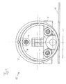
- the cutting and creasing device 10 has for this purpose two substantially round creasing tool halves 12 and 14.
- the cutting and creasing device 10 has for this purpose two substantially round creasing tool halves 12 and 14.
- Groove cutter halves 12, 14 are arranged in the axial direction next to one another such that a cutting device 16 (which will be described below) can be arranged between them.
- the cutting and scoring device 10 When a work piece 11 to be machined is scored with the cutting and scoring device 10, the cutting and scoring device 10 is pressed onto the region of the workpiece 11 to be scored, and then a relative movement between the workpiece 11 and the cutting and scoring device 10 is obtained in the scoring direction. In this case, both the workpiece 11 relative to the cutting and creasing device 10 and the cutting and creasing device 10 can be moved relative to the workpiece.
- the two rill mold halves 12, 14 have a different diameter, wherein the different diameter between 5-40 % , preferably 10-20%, more preferably 15% may be. By this difference in diameter, it is possible to prevent the groove 11 from becoming too high when the workpiece 11 is being grooved, so that the workpiece 11 is prevented from tearing when the groove is being cut.
- the two rill mold halves 12, 14 are arranged so that both halves 12, 14 rest flat on the workpiece 11, at least in a small section area.
- the grooving tool half 12 with the larger diameter performs a first compressing operation, which in the further course is supported by the smaller grooving tool half 14, up to the two grooving tool halves at the location of the maximum compression rest on the workpiece.
- Fig. 2 clarifies this connection.
- the two grooving halves 12, 14 are formed in cross section so suitable to produce a suitable score line geometry.
- Other shapes are also conceivable.
- the cutting and creasing device 10 it is additionally possible with the cutting and creasing device 10 according to the invention to introduce a cut into the workpiece 11 with the cutting device 16.
- the cutting device 16 is designed so that it is between a retracted position (see Fig. 1-3 ) and an extended position (see Fig. 4 ) can be moved.
- the cutting device can additionally interact with the two scarf tool halves 12, 14, in that the two scraper tool halves 12, 14 additionally compress the workpiece 11 during cutting, so that a smaller cutting depth is required.
- the process of the cutter 16 between the operating position in which it performs a cutting processing of the workpiece 11, and the rest position (see Fig. 1-3 ), in which no cutting machining is performed, can be done by means of a suitable servomotor or manually.
- the cutting device 16 can be designed both as a cutting device which completely cuts through the workpiece, and as a perforating cutting device, which only partially cuts through the workpiece. In this way, it is possible to cut the workpiece, especially the cartons and the like, only partially and then further processed.
Landscapes
- Engineering & Computer Science (AREA)
- Mechanical Engineering (AREA)
- Life Sciences & Earth Sciences (AREA)
- Forests & Forestry (AREA)
- Making Paper Articles (AREA)
- Machines For Manufacturing Corrugated Board In Mechanical Paper-Making Processes (AREA)
Description
- Die vorliegende Erfindung betrifft eine Schneid- und Rillvorrichtung sowie ein Verfahren zum Schneiden und/oder Rillen. Derartige Vorrichtungen bzw. Verfahren werden eingesetzt, um beispielsweise in der Verpackungsindustrie bei der Produktion von faltbaren Kartonagen bzw. Kartonverpackungen diese mit einer Rille bzw. auch mit einer Nut zu versehen, entlang derer der Karton im Anschluss gefaltet werden kann. Zusätzlich ist es bei derartigen Vorrichtungen bzw. Verfahren wünschenswert, dass in den Karton auch ein Schnitt eingebracht werden kann, so dass gewünschte Kartonformate, insbesondere bei der Fertigung mit der Losgröße 1, ohne große Umrüstzeiten herstellbar sind.
- Die
WO 2006/091149 A1 beschreibt eine Schneid- und Rillradanordnung, mittels welcher es möglich ist, bei einem zu bearbeitenden Werkstück sowohl einen Schneid- als auch einen Rillvorgang durchzuführen. Diese Schneid- und Rillradanordnung ist so aufgebaut, dass zwei Rillradhälften mit gleichem radialen Durchmesser sowie ein dazwischen angeordnetes Schneidwerkzeug vorgesehen sind. Durch Anordnen des Schneidmessers zwischen den Rillrädern ist es möglich, das Werkstück beim Schneiden mit dem Schneidmesser zusätzlich mittels der Rillräder zu komprimieren, so dass es möglich ist, das Schneidmesser mit einem kleineren Durchmesser auszuführen. - Diese Schneid- und Rillradanordnung weist jedoch den Nachtteil auf, dass bei hohen Verarbeitungsgeschwindigkeiten bei Rillvorgängen die Komprimierungsrate, mit der das Werkstück beim Rillen komprimiert wird, sehr hoch ist, was dazu führt, dass das Werkstück nicht nur gerillt wird, sondern dass es zum Einreißen des Werkstücks, insbesondere des Kartons, kommt. Vor Allem bei dicken Wellpappen ist dies häufig zu beobachten.
- Der Erfindung liegt daher die Aufgabe zugrunde, eine Schneid-und Rillvorrichtung sowie ein Verfahren zum Schneiden und/oder Rillen zu schaffen, das die bekannten Probleme aus dem Stand der Technik löst und ferner dazu geeignet ist, um bei hohen Bearbeitungsgeschwindigkeiten ein sicheres und zuverlässiges Rillen bzw. Komprimieren des Werkstücks zu ermöglichen.
- Die Lösung der Aufgabe erfolgt durch den Gegenstand des Patentanspruchs 1. Bevorzugte Ausgestaltungen ergeben sich aus den Unteransprüchen.
- Der Erfindung liegt der Gedanke zugrunde, die Rillwerkzeughälften einer Schneid- und Rillvorrichtung derart geschickt einzusetzen, dass die Komprimierungsrate trotz hoher Bearbeitungsgeschwindigkeit beim Rillen optimal dem Werkstück angepasst werden kann.
- Demgemäß umfasst die erfindungsgemäße Schneid- und Rillvorrichtung, insbesondere für Kartonagen, zwei runde, insbesondere kreisrunde, Rillwerkzeughälften und eine zwischen den beiden Rillwerkzeughälften angeordnete Schneideinrichtung, wobei die Schneideinrichtung zwischen einer Ruheposition radial innerhalb zwischen den Rillwerkzeughälften und einer Betriebsposition radial außerhalb der Rillwerkzeughälften beweglich ist. Dabei weisen die zwei Rillwerkzeughälften jeweils unterschiedlich große Durchmesser auf.
- Eine Rillwerkzeughälfte im Sinne der Erfindung ist dabei jede Art von Werkzeug, das zum Rillen von Kartonagen oder dergleichen geeignet ist. Die Rillwerkzeughälften sind dabei rund, insbesondere kreisrund, ausgeführt und weisen in ihrem Umfang eine Fläche auf, die so geformt ist, um das Rillen der Kartonagen vorteilhaft durchführen zu können. Dazu sind runde sowie teilweise auch flache Querschnitte geeignet.
- Mit der erfindungsgemäßen Schneid- und Rillvorrichtung ist es bedingt dadurch, dass die zwei Rillwerkzeughälften unterschiedlich große Durchmesser aufweisen, möglich, beim Rillen und/oder beim Schneiden das zu bearbeitende Werkstück schonend zu komprimieren, da die Rillwerkzeughälfte mit dem größeren Durchmesser mit Vorteil so eingesetzt werden kann, dass diese zunächst mit dem Komprimieren des Werkstücks beginnt und anschließend die Rillwerkzeughälfte mit dem kleineren Durchmesser die Rillwerkzeughälfte mit dem größeren Durchmesser beim vollständigen Komprimieren unterstützt. Auf diese Weise kann zum Einen eine hohe Bearbeitungsgeschwindigkeit der Schneid- und Rillvorrichtung umgesetzt werden und zum Anderen kann die Komprimierungsrate beim Rillen derart abgesenkt werden, dass eine Beschädigung, insbesondere ein Einreißen, des Materials, insbesondere des Kartons bzw. der Wellpappe, vermieden werden kann. Somit ist es möglich, den Anteil an Ausschuss bei der Produktion wesentlich zu verringern, wodurch Fertigungskosten eingespart werden können.
- Gemäß einer Ausführungsform sind die beiden
Rillwerkzeughälften mit unterschiedlichem Durchmesser so angeordnet, dass zumindest in einem Abschnitt des Bearbeitungsbereichs der Abstand der zwei Rillwerkzeughälften zu einem zu bearbeitenden Werkstück gleich ist. Auf diese Weise ist es mit Vorteil möglich, einen Bearbeitungsbereich zu schaffen, in dem das Werkstück mittels beider Rillwerkzeughälften derart komprimiert wird, dass ein zuverlässiges und ausreichendes Rillen des Werkstücks ermöglich wird. - Gemäß einer weiteren besonders bevorzugten Ausführungsform beträgt der Unterschied des Durchmessers der zwei Rillwerkzeughälften zwischen 5 und 40 %, bevorzugt zwischen 10 und 20 %, besonders bevorzugt ca. 15 %. Mit einem Rillwerkzeughälftendurchmesserunterschied in diesem Bereich kann besonders zuverlässig ein Einreißen oder dergleichen des Werkstücks vermieden werden, so dass ein besonders zuverlässiges und gutes Rillen ermöglicht wird.
- Gemäß einer weiteren besonders bevorzugten Ausführungsform der Erfindung sind die beiden Rillwerkzeughälften so angeordnet, dass die Rillwerkzeughälfte mit dem größeren Durchmesser zuerst einen Rillvorgang einleitet. Auf diese Weise ist es bedingt durch den größeren Durchmesser und durch das zunächst nur mit einer Rillwerkzeughälfte durchgeführte Rillen möglich, die Komprimierungsrate beim Rillen derart vorteilhaft zu beeinflussen, dass ein Einreißen des Werkstücks oder dergleichen vermieden wird.
- Die erfindungsgemäße Vorrichtung kann dabei gemäß einer weiteren vorteilhaften Ausführungsform eine Schneideinrichtung mit einem im Wesentlichen kreisrunden Schneidmesser und/oder eine Schneideinrichtung, die eine Perforierschneideinrichtung ist, aufweisen. Alternative Schneideinrichtungen sind ebenfalls denkbar.
- Gemäß einer weiteren besonders bevorzugten Ausführungsform betrifft die Erfindung ein Verfahren zum Schneiden und/oder Rillen von Werkstücken, bei dem die Rillwerkzeughälfte mit dem größeren Durchmesser zunächst mit dem Komprimieren bzw. Rillen des Werkstücks beginnt und anschließend beide Rillwerkzeughälften das Werkstück komprimieren. Auf diese Weise ist es besonders vorteilhaft möglich, das Werkstück schonend zu komprimieren, da die Rillwerkzeughälften nacheinander das Komprimieren initiieren.
-
-
Fig. 1 zeigt eine perspektivische Ansicht einer Schneidund Rillvorrichtung, -
Fig. 2 zeigt eine erste Seitenansicht der Schneideinrichtung, -
Fig. 3 zeigt eine relativ zuFig. 2 um 90 ° gedrehte Schneideinrichtung und -
Fig. 4 zeigt eine Seitenansicht einer Rill- und Schneideinrichtung mit ausgefahrener Schneideinrichtung. - Im Folgenden wird eine erfindungsgemäße Schneid- und Rillvorrichtung 10 anhand eines beispielhaften Ausführungsbeispiels beschrieben. Die Schneid- und Rillvorrichtung 10 wird bevorzugt bei der Bearbeitung von Karton, Kartonagen, Pappe, Wellpappe und dergleichen eingesetzt.
- Die Schneid- und Rillvorrichtung 10 wird dabei zum Schneiden und Rillen von Werkstücken 11 verwendet, wobei Rillen einen Vorgang bezeichnet, bei dem durch Aufbringen von Druck auf das Werkstück 11 eine Nut in selbiges eingebracht wird, um so eine "Rille" zu erzeugen. Entlang dieser Rille ist das Werkstück im Anschluss leichter faltbar bzw. falzbar.
- Die Schneid- und Rillvorrichtung 10 weist dazu zwei im Wesentlichen runde Rillwerkzeughälften 12 und 14 auf. Die
- Rillwerkzeughälften 12, 14 sind in Axialrichtung derart nebeneinander angeordnet, dass zwischen ihnen eine Schneideinrichtung 16 (diese wird weiter unten beschrieben) angeordnet werden kann.
- Beim Rillen eines zu bearbeitenden Werkstücks 11 mit der Schneid- und Rillvorrichtung 10 wird die Schneid- und Rillvorrichtung 10 auf dem zu rillenden Bereich des Werkstücks 11 aufgedrückt und anschließend wird in Rillrichtung eine Relativbewegung zwischen Werkstück 11 und Schneid- und Rillvorrichtung 10 erwirkt. Dabei kann sowohl das Werkstück 11 relativ zur Schneid- und Rillvorrichtung 10 als auch die Schneid- und Rillvorrichtung 10 relativ zum Werkstück verfahren werden.
- Die (angetriebene) Bewegung der beiden Rillwerkzeughälften 12, 14 wird durch die zumindest teilweise an dem Rollenhalter 18 angebrachten Rollen 20 geführt.
- Die beiden Rillwerkzeughälften 12, 14 weisen einen unterschiedlichen Durchmesser auf, wobei der unterschiedliche Durchmesser zwischen 5-40 %, bevorzugt 10-20 %, besonders bevorzugt 15 %, betragen kann. Durch diesen Durchmesserunterschied ist es beim Rillen des Werkstücks 11 möglich zu vermeiden, dass bei hoher Bearbeitungsgeschwindigkeit die Komprimierungsrate beim Rillen zu hoch wird, so dass vermieden wird, dass das Werkstück 11 beim Rillen einreißt. Die beiden Rillwerkzeughälften 12, 14 sind dabei so angeordnet, dass beide Hälften 12, 14 zumindest in einem kleinen Abschnittsbereich plan auf dem Werkstück 11 aufliegen. In anderen Worten führt also zunächst die Rillwerkzeughälfte 12 mit dem größeren Durchmesser einen ersten Komprimierungsvorgang durch, der im weiteren Verlauf von der kleineren Rillwerkzeughälfte 14 unterstützt wird, bis beiden Rillwerkzeughälften an der Stelle der maximalen Komprimierung auf dem Werkstück aufliegen.
Fig. 2 verdeutlicht diesen Zusammenhang. - Wie in
Fig, 3 zu erkennen ist, sind die beiden Rillwerkzeughälften 12, 14 im Querschnitt derart geeignet geformt, um eine geeignete Rillliniengeometrie herzustellen. Andere Formen sind ebenfalls denkbar. - Ferner ist es mit der erfindungsgemäßen Schneid- und Rillvorrichtung 10 zusätzlich möglich, einen Schnitt in das Werkstück 11 mit der Schneideinrichtung 16 einzubringen. Die Schneideinrichtung 16 ist dabei so gestaltet, dass sie zwischen einer zurückgezogenen Position (siehe
Fig. 1-3 ) und einer ausgefahrenen Position (sieheFig. 4 ) bewegt werden kann. Beim Schneiden kann die Schneideinrichtung zusätzlich mit den beiden Rillwerkzeughälften 12, 14 zusammenwirken, indem die beiden Rillwerkzeughälften 12, 14 das Werkstück 11 beim Schneiden zusätzlich komprimieren, so dass eine geringere Schnitttiefe erforderlich ist. Das Verfahren der Schneideinrichtung 16 zwischen der Betriebposition, in der diese eine Schneidbearbeitung des Werkstücks 11 durchführt, und der Ruheposition (sieheFig. 1-3 ), in der keine Schneidbearbeitung durchgeführt wird, kann mittels eines geeigneten Stellmotors oder auch manuell erfolgen. - Die Schneideinrichtung 16 kann sowohl als eine Schneideinrichtung ausgeführt sein, die das Werkstück vollständig durchtrennt, als auch als eine Perforierschneideinrichtung, die das Werkstück lediglich teilweise durchtrennt. Auf diese Weise ist es möglich, das Werkstück, insbesondere die Kartons und dergleichen, lediglich teilweise anzuschneiden und anschließend weiterzubearbeiten.
Claims (7)
- Schneid- und Rillvorrichtung (10), insbesondere für Kartonagen, umfassend:zwei runde Rillwerkzeughälften (12; 14), undeine zwischen den beiden Rillwerkzeughälften (12; 14) angeordnete Schneideinrichtung (16),wobei die Schneideinrichtung (16) zwischen einer Ruheposition radial innerhalb zwischen den Rillwerkzeughälften (12; 14) und einer Betriebsposition radial außerhalb der Rillwerkzeughälften (12; 14) beweglich ist,dadurch gekennzeichnet, dassdie zwei Rillwerkzeughälften (12; 14) unterschiedlich große Durchmesser aufweisen.
- Schneid- und Rillvorrichtung nach Anspruch 1, dadurch gekennzeichnet, dass die zwei Rillwerkzeughälften (12; 14) so angeordnet sind, dass zumindest in einem Abschnitt des Bearbeitungsbereichs der Abstand der zwei Rillwerkzeughälften (12; 14) zu einem zu bearbeitenden Werkstück (11) gleich ist.
- Schneid- und Rillvorrichtung nach Anspruch 1 oder 2, dadurch gekennzeichnet, dass der Unterschied des Durchmessers der zwei Rillwerkzeughälften (12; 14) zwischen 5 und 40 %, bevorzugt zwischen 10 und 20 %, besonders bevorzugt ca. 15 % beträgt.
- Schneid- und Rillvorrichtung nach einem der vorhergehenden Ansprüche, dadurch gekennzeichnet, dass die Rillwerkzeughälften (12; 14) so angeordnet sind, dass die Rillwerkzeughälfte (12) mit dem größeren Durchmesser einen Rillvorgang zuerst einleitet.
- Schneid- und Rillvorrichtung nach einem der Ansprüche 1-4, dadurch gekennzeichnet, dass die Schneideinrichtung (16) ein im Wesentlichen kreisrundes Schneidmesser aufweist.
- Schneid- und Rillvorrichtung nach einem der Ansprüche 1-4, dadurch gekennzeichnet, dass die Schneideinrichtung (16) eine Perforierschneideinrichtung ist.
- Verfahren zum Schneiden und/oder Rillen von Werkstücken unter Verwendung einer Schneid- und Rillvorrichtung nach einem der Ansprüche 1-6, dadurch gekennzeichnet, dass beim Rillen die Rillwerkzeughälfte (12) mit dem größeren Durchmesser zunächst mit dem Komprimieren des Werkstücks beginnt und anschließend beide Rillwerkzeughälften (12; 14) das Werkstück (11) komprimieren.
Priority Applications (2)
| Application Number | Priority Date | Filing Date | Title |
|---|---|---|---|
| EP11150372.8A EP2474397B1 (de) | 2011-01-07 | 2011-01-07 | Schneid- und Rillvorrichtung und Verfahren zum Schneiden und/oder Rillen |
| US13/344,933 US20120178605A1 (en) | 2011-01-07 | 2012-01-06 | Cutting and grooving device as well as method for cutting and/or grooving |
Applications Claiming Priority (1)
| Application Number | Priority Date | Filing Date | Title |
|---|---|---|---|
| EP11150372.8A EP2474397B1 (de) | 2011-01-07 | 2011-01-07 | Schneid- und Rillvorrichtung und Verfahren zum Schneiden und/oder Rillen |
Publications (2)
| Publication Number | Publication Date |
|---|---|
| EP2474397A1 EP2474397A1 (de) | 2012-07-11 |
| EP2474397B1 true EP2474397B1 (de) | 2013-07-03 |
Family
ID=43934854
Family Applications (1)
| Application Number | Title | Priority Date | Filing Date |
|---|---|---|---|
| EP11150372.8A Not-in-force EP2474397B1 (de) | 2011-01-07 | 2011-01-07 | Schneid- und Rillvorrichtung und Verfahren zum Schneiden und/oder Rillen |
Country Status (2)
| Country | Link |
|---|---|
| US (1) | US20120178605A1 (de) |
| EP (1) | EP2474397B1 (de) |
Cited By (1)
| Publication number | Priority date | Publication date | Assignee | Title |
|---|---|---|---|---|
| CN106003831A (zh) * | 2016-07-05 | 2016-10-12 | 宜昌金海科技股份有限公司 | 一种大直径圆形顶盖内侧边内衬自动压装粘合设备及使用方法 |
Families Citing this family (4)
| Publication number | Priority date | Publication date | Assignee | Title |
|---|---|---|---|---|
| DE102012220233B4 (de) | 2012-11-07 | 2019-03-28 | Ligmatech Automationssysteme Gmbh | Bearbeitungsvorrichtung mit einem drehbaren Werkzeugaufnehmer |
| EP3043945B1 (de) * | 2013-09-11 | 2021-09-29 | Profilator GmbH & Co. KG | Wälzschälverfahren und zugehörige vorrichtung |
| EP3254840B1 (de) | 2016-06-09 | 2019-05-08 | Neopost Technologies | Welleinheit für die erstellung von faltlinien in karton, vorrichtung zum bilden von rohlingen umfassend eine solche welleinheit und verfahren für die erstellung von faltlinien in karton |
| EP3521006B1 (de) | 2018-01-31 | 2020-11-25 | Quadient Technologies France | Verfahren und system zur herstellung von massgefertigten kartonzuschnitten für verpackungen sowie verfahren und system zur automatischen verpackung von versandsets in kisten |
Family Cites Families (1)
| Publication number | Priority date | Publication date | Assignee | Title |
|---|---|---|---|---|
| BRPI0607598B1 (pt) | 2005-02-25 | 2018-06-26 | Niklas Pettersson | Uma montagem de roda de corte e dobra e um método para corte e dobra de um material compressível |
-
2011
- 2011-01-07 EP EP11150372.8A patent/EP2474397B1/de not_active Not-in-force
-
2012
- 2012-01-06 US US13/344,933 patent/US20120178605A1/en not_active Abandoned
Cited By (1)
| Publication number | Priority date | Publication date | Assignee | Title |
|---|---|---|---|---|
| CN106003831A (zh) * | 2016-07-05 | 2016-10-12 | 宜昌金海科技股份有限公司 | 一种大直径圆形顶盖内侧边内衬自动压装粘合设备及使用方法 |
Also Published As
| Publication number | Publication date |
|---|---|
| US20120178605A1 (en) | 2012-07-12 |
| EP2474397A1 (de) | 2012-07-11 |
Similar Documents
| Publication | Publication Date | Title |
|---|---|---|
| EP2845724B1 (de) | Vorrichtung und Verfahren zum Rillen von Wellpappe und Vollpappe | |
| EP2474397B1 (de) | Schneid- und Rillvorrichtung und Verfahren zum Schneiden und/oder Rillen | |
| EP4093565B1 (de) | Verfahren und drahtverarbeitungsmaschine zur herstellung konfektionierter formteile | |
| WO2011134903A1 (de) | Turbinenschaufelrohling sowie verfahren und vorrichtung zum bearbeiten eines turbinenschaufelrohlings | |
| EP2147761A2 (de) | Verfahren zum Aufteilen großformatiger plattenförmiger Werkstücke, sowie Plattenaufteilanlage | |
| EP3197630B1 (de) | Vorrichtung zur herstellung von wickelschläuchen | |
| EP2886272B1 (de) | Vorrichtung und Verfahren zum Bearbeiten eines Werkstücks | |
| DE2104293A1 (de) | Stanzvorrichtung | |
| EP3144133A1 (de) | Vorrichtung zum nuten von materialbogen | |
| DE102015011716A1 (de) | Werkzeug und Verfahren zum Entgraten von Werkstücken | |
| DE4116868A1 (de) | Verfahren zur bearbeitung von werkstuecken, insbesondere zur funkenerosiven bearbeitung von werkstuecken mittels eines drahtes, elektroerosions-schneidevorrichtung und mittel zur sicherung von formstuecken bei der bearbeitung von werkstuecken | |
| EP3088096A1 (de) | Vorrichtungen und verfahren zum druckumformen von verbindungsstegen zwischen werkstückteilen eines plattenartigen werkstücks | |
| WO2019158404A1 (de) | Vorrichtung zur längstrennung eines rohres | |
| EP2623278A1 (de) | Bearbeitungsmaschine und Verfahren für Laschenfreischnitte | |
| EP1990152B1 (de) | Kantenanleimaggregat und Verfahren zum Anleimen von Kantenmaterial | |
| WO2013021053A1 (de) | Verfahren und vorrichtung zum schnellen verbinden eines bandendes mit einem bandanfang von metallbändern | |
| EP3420246B1 (de) | Verfahren zur herstellung endloser metallbänder beliebiger breite | |
| EP2311611A2 (de) | Verfahren und Werkzeug zum Herstellen von Zuschnitten aus bahnförmigem Material | |
| EP3330070A2 (de) | Vorrichtung und verfahren zum rillen von wellpappe und vollpappe | |
| DE102010033191A1 (de) | Vorrichtung zum Schneiden von hochfesten Werkstücken | |
| DE10322302B4 (de) | Anlage zur Herstellung von Platinen aus bandförmigem Material | |
| DE69806140T2 (de) | Vorrichtung zum kaltschneiden von länglichen gegenständen entlang einer längsachse | |
| DE102004002267B3 (de) | Einrichtung und Verfahren zur Herstellung eines Hohl- oder Schalenprofils | |
| DE10323738B3 (de) | Verfahren zur Herstellung eines umfänglich geschlossenen Hohlprofils | |
| DE102008010588A1 (de) | Vorrichtung zur Herstellung eines Kantenschutzes |
Legal Events
| Date | Code | Title | Description |
|---|---|---|---|
| PUAI | Public reference made under article 153(3) epc to a published international application that has entered the european phase |
Free format text: ORIGINAL CODE: 0009012 |
|
| AK | Designated contracting states |
Kind code of ref document: A1 Designated state(s): AL AT BE BG CH CY CZ DE DK EE ES FI FR GB GR HR HU IE IS IT LI LT LU LV MC MK MT NL NO PL PT RO RS SE SI SK SM TR |
|
| AX | Request for extension of the european patent |
Extension state: BA ME |
|
| GRAP | Despatch of communication of intention to grant a patent |
Free format text: ORIGINAL CODE: EPIDOSNIGR1 |
|
| 17P | Request for examination filed |
Effective date: 20121217 |
|
| RIC1 | Information provided on ipc code assigned before grant |
Ipc: B26D 1/14 20060101AFI20130116BHEP Ipc: B31F 1/10 20060101ALI20130116BHEP Ipc: B26D 7/27 20060101ALI20130116BHEP |
|
| GRAS | Grant fee paid |
Free format text: ORIGINAL CODE: EPIDOSNIGR3 |
|
| GRAA | (expected) grant |
Free format text: ORIGINAL CODE: 0009210 |
|
| AK | Designated contracting states |
Kind code of ref document: B1 Designated state(s): AL AT BE BG CH CY CZ DE DK EE ES FI FR GB GR HR HU IE IS IT LI LT LU LV MC MK MT NL NO PL PT RO RS SE SI SK SM TR |
|
| REG | Reference to a national code |
Ref country code: GB Ref legal event code: FG4D Free format text: NOT ENGLISH |
|
| REG | Reference to a national code |
Ref country code: AT Ref legal event code: REF Ref document number: 619438 Country of ref document: AT Kind code of ref document: T Effective date: 20130715 Ref country code: CH Ref legal event code: EP |
|
| REG | Reference to a national code |
Ref country code: IE Ref legal event code: FG4D Free format text: LANGUAGE OF EP DOCUMENT: GERMAN |
|
| REG | Reference to a national code |
Ref country code: DE Ref legal event code: R096 Ref document number: 502011000973 Country of ref document: DE Effective date: 20130829 |
|
| PG25 | Lapsed in a contracting state [announced via postgrant information from national office to epo] |
Ref country code: SI Free format text: LAPSE BECAUSE OF FAILURE TO SUBMIT A TRANSLATION OF THE DESCRIPTION OR TO PAY THE FEE WITHIN THE PRESCRIBED TIME-LIMIT Effective date: 20130703 |
|
| REG | Reference to a national code |
Ref country code: NL Ref legal event code: VDEP Effective date: 20130703 |
|
| REG | Reference to a national code |
Ref country code: LT Ref legal event code: MG4D |
|
| PG25 | Lapsed in a contracting state [announced via postgrant information from national office to epo] |
Ref country code: IS Free format text: LAPSE BECAUSE OF FAILURE TO SUBMIT A TRANSLATION OF THE DESCRIPTION OR TO PAY THE FEE WITHIN THE PRESCRIBED TIME-LIMIT Effective date: 20131103 Ref country code: SE Free format text: LAPSE BECAUSE OF FAILURE TO SUBMIT A TRANSLATION OF THE DESCRIPTION OR TO PAY THE FEE WITHIN THE PRESCRIBED TIME-LIMIT Effective date: 20130703 Ref country code: PT Free format text: LAPSE BECAUSE OF FAILURE TO SUBMIT A TRANSLATION OF THE DESCRIPTION OR TO PAY THE FEE WITHIN THE PRESCRIBED TIME-LIMIT Effective date: 20131104 Ref country code: CY Free format text: LAPSE BECAUSE OF FAILURE TO SUBMIT A TRANSLATION OF THE DESCRIPTION OR TO PAY THE FEE WITHIN THE PRESCRIBED TIME-LIMIT Effective date: 20130904 Ref country code: NO Free format text: LAPSE BECAUSE OF FAILURE TO SUBMIT A TRANSLATION OF THE DESCRIPTION OR TO PAY THE FEE WITHIN THE PRESCRIBED TIME-LIMIT Effective date: 20131003 Ref country code: LT Free format text: LAPSE BECAUSE OF FAILURE TO SUBMIT A TRANSLATION OF THE DESCRIPTION OR TO PAY THE FEE WITHIN THE PRESCRIBED TIME-LIMIT Effective date: 20130703 Ref country code: HR Free format text: LAPSE BECAUSE OF FAILURE TO SUBMIT A TRANSLATION OF THE DESCRIPTION OR TO PAY THE FEE WITHIN THE PRESCRIBED TIME-LIMIT Effective date: 20130703 |
|
| PG25 | Lapsed in a contracting state [announced via postgrant information from national office to epo] |
Ref country code: LV Free format text: LAPSE BECAUSE OF FAILURE TO SUBMIT A TRANSLATION OF THE DESCRIPTION OR TO PAY THE FEE WITHIN THE PRESCRIBED TIME-LIMIT Effective date: 20130703 Ref country code: GR Free format text: LAPSE BECAUSE OF FAILURE TO SUBMIT A TRANSLATION OF THE DESCRIPTION OR TO PAY THE FEE WITHIN THE PRESCRIBED TIME-LIMIT Effective date: 20131004 Ref country code: NL Free format text: LAPSE BECAUSE OF FAILURE TO SUBMIT A TRANSLATION OF THE DESCRIPTION OR TO PAY THE FEE WITHIN THE PRESCRIBED TIME-LIMIT Effective date: 20130703 Ref country code: PL Free format text: LAPSE BECAUSE OF FAILURE TO SUBMIT A TRANSLATION OF THE DESCRIPTION OR TO PAY THE FEE WITHIN THE PRESCRIBED TIME-LIMIT Effective date: 20130703 Ref country code: ES Free format text: LAPSE BECAUSE OF FAILURE TO SUBMIT A TRANSLATION OF THE DESCRIPTION OR TO PAY THE FEE WITHIN THE PRESCRIBED TIME-LIMIT Effective date: 20131014 Ref country code: FI Free format text: LAPSE BECAUSE OF FAILURE TO SUBMIT A TRANSLATION OF THE DESCRIPTION OR TO PAY THE FEE WITHIN THE PRESCRIBED TIME-LIMIT Effective date: 20130703 |
|
| PG25 | Lapsed in a contracting state [announced via postgrant information from national office to epo] |
Ref country code: CY Free format text: LAPSE BECAUSE OF FAILURE TO SUBMIT A TRANSLATION OF THE DESCRIPTION OR TO PAY THE FEE WITHIN THE PRESCRIBED TIME-LIMIT Effective date: 20130703 |
|
| PG25 | Lapsed in a contracting state [announced via postgrant information from national office to epo] |
Ref country code: EE Free format text: LAPSE BECAUSE OF FAILURE TO SUBMIT A TRANSLATION OF THE DESCRIPTION OR TO PAY THE FEE WITHIN THE PRESCRIBED TIME-LIMIT Effective date: 20130703 Ref country code: DK Free format text: LAPSE BECAUSE OF FAILURE TO SUBMIT A TRANSLATION OF THE DESCRIPTION OR TO PAY THE FEE WITHIN THE PRESCRIBED TIME-LIMIT Effective date: 20130703 Ref country code: SK Free format text: LAPSE BECAUSE OF FAILURE TO SUBMIT A TRANSLATION OF THE DESCRIPTION OR TO PAY THE FEE WITHIN THE PRESCRIBED TIME-LIMIT Effective date: 20130703 Ref country code: RO Free format text: LAPSE BECAUSE OF FAILURE TO SUBMIT A TRANSLATION OF THE DESCRIPTION OR TO PAY THE FEE WITHIN THE PRESCRIBED TIME-LIMIT Effective date: 20130703 Ref country code: CZ Free format text: LAPSE BECAUSE OF FAILURE TO SUBMIT A TRANSLATION OF THE DESCRIPTION OR TO PAY THE FEE WITHIN THE PRESCRIBED TIME-LIMIT Effective date: 20130703 |
|
| PLBE | No opposition filed within time limit |
Free format text: ORIGINAL CODE: 0009261 |
|
| STAA | Information on the status of an ep patent application or granted ep patent |
Free format text: STATUS: NO OPPOSITION FILED WITHIN TIME LIMIT |
|
| PG25 | Lapsed in a contracting state [announced via postgrant information from national office to epo] |
Ref country code: IT Free format text: LAPSE BECAUSE OF FAILURE TO SUBMIT A TRANSLATION OF THE DESCRIPTION OR TO PAY THE FEE WITHIN THE PRESCRIBED TIME-LIMIT Effective date: 20130703 |
|
| 26N | No opposition filed |
Effective date: 20140404 |
|
| REG | Reference to a national code |
Ref country code: DE Ref legal event code: R097 Ref document number: 502011000973 Country of ref document: DE Effective date: 20140404 |
|
| BERE | Be: lapsed |
Owner name: LIGMATECH AUTOMATIONSSYSTEME G.M.B.H. Effective date: 20140131 |
|
| REG | Reference to a national code |
Ref country code: DE Ref legal event code: R119 Ref document number: 502011000973 Country of ref document: DE |
|
| PG25 | Lapsed in a contracting state [announced via postgrant information from national office to epo] |
Ref country code: LU Free format text: LAPSE BECAUSE OF FAILURE TO SUBMIT A TRANSLATION OF THE DESCRIPTION OR TO PAY THE FEE WITHIN THE PRESCRIBED TIME-LIMIT Effective date: 20140107 |
|
| REG | Reference to a national code |
Ref country code: CH Ref legal event code: PL |
|
| REG | Reference to a national code |
Ref country code: DE Ref legal event code: R119 Ref document number: 502011000973 Country of ref document: DE Effective date: 20140801 |
|
| PG25 | Lapsed in a contracting state [announced via postgrant information from national office to epo] |
Ref country code: DE Free format text: LAPSE BECAUSE OF NON-PAYMENT OF DUE FEES Effective date: 20140801 Ref country code: CH Free format text: LAPSE BECAUSE OF NON-PAYMENT OF DUE FEES Effective date: 20140131 Ref country code: LI Free format text: LAPSE BECAUSE OF NON-PAYMENT OF DUE FEES Effective date: 20140131 |
|
| REG | Reference to a national code |
Ref country code: FR Ref legal event code: ST Effective date: 20140930 |
|
| REG | Reference to a national code |
Ref country code: IE Ref legal event code: MM4A |
|
| PG25 | Lapsed in a contracting state [announced via postgrant information from national office to epo] |
Ref country code: FR Free format text: LAPSE BECAUSE OF NON-PAYMENT OF DUE FEES Effective date: 20140131 |
|
| PG25 | Lapsed in a contracting state [announced via postgrant information from national office to epo] |
Ref country code: BE Free format text: LAPSE BECAUSE OF NON-PAYMENT OF DUE FEES Effective date: 20140131 Ref country code: IE Free format text: LAPSE BECAUSE OF NON-PAYMENT OF DUE FEES Effective date: 20140107 |
|
| PG25 | Lapsed in a contracting state [announced via postgrant information from national office to epo] |
Ref country code: MC Free format text: LAPSE BECAUSE OF FAILURE TO SUBMIT A TRANSLATION OF THE DESCRIPTION OR TO PAY THE FEE WITHIN THE PRESCRIBED TIME-LIMIT Effective date: 20130703 |
|
| GBPC | Gb: european patent ceased through non-payment of renewal fee |
Effective date: 20150107 |
|
| PG25 | Lapsed in a contracting state [announced via postgrant information from national office to epo] |
Ref country code: GB Free format text: LAPSE BECAUSE OF NON-PAYMENT OF DUE FEES Effective date: 20150107 |
|
| PG25 | Lapsed in a contracting state [announced via postgrant information from national office to epo] |
Ref country code: MT Free format text: LAPSE BECAUSE OF FAILURE TO SUBMIT A TRANSLATION OF THE DESCRIPTION OR TO PAY THE FEE WITHIN THE PRESCRIBED TIME-LIMIT Effective date: 20130703 |
|
| PG25 | Lapsed in a contracting state [announced via postgrant information from national office to epo] |
Ref country code: SM Free format text: LAPSE BECAUSE OF FAILURE TO SUBMIT A TRANSLATION OF THE DESCRIPTION OR TO PAY THE FEE WITHIN THE PRESCRIBED TIME-LIMIT Effective date: 20130703 |
|
| PG25 | Lapsed in a contracting state [announced via postgrant information from national office to epo] |
Ref country code: RS Free format text: LAPSE BECAUSE OF FAILURE TO SUBMIT A TRANSLATION OF THE DESCRIPTION OR TO PAY THE FEE WITHIN THE PRESCRIBED TIME-LIMIT Effective date: 20130703 Ref country code: BG Free format text: LAPSE BECAUSE OF FAILURE TO SUBMIT A TRANSLATION OF THE DESCRIPTION OR TO PAY THE FEE WITHIN THE PRESCRIBED TIME-LIMIT Effective date: 20130703 |
|
| PG25 | Lapsed in a contracting state [announced via postgrant information from national office to epo] |
Ref country code: TR Free format text: LAPSE BECAUSE OF FAILURE TO SUBMIT A TRANSLATION OF THE DESCRIPTION OR TO PAY THE FEE WITHIN THE PRESCRIBED TIME-LIMIT Effective date: 20130703 Ref country code: HU Free format text: LAPSE BECAUSE OF FAILURE TO SUBMIT A TRANSLATION OF THE DESCRIPTION OR TO PAY THE FEE WITHIN THE PRESCRIBED TIME-LIMIT; INVALID AB INITIO Effective date: 20110107 |
|
| REG | Reference to a national code |
Ref country code: AT Ref legal event code: MM01 Ref document number: 619438 Country of ref document: AT Kind code of ref document: T Effective date: 20160107 |
|
| PG25 | Lapsed in a contracting state [announced via postgrant information from national office to epo] |
Ref country code: AT Free format text: LAPSE BECAUSE OF NON-PAYMENT OF DUE FEES Effective date: 20160107 |
|
| PG25 | Lapsed in a contracting state [announced via postgrant information from national office to epo] |
Ref country code: MK Free format text: LAPSE BECAUSE OF FAILURE TO SUBMIT A TRANSLATION OF THE DESCRIPTION OR TO PAY THE FEE WITHIN THE PRESCRIBED TIME-LIMIT Effective date: 20130703 |
|
| PG25 | Lapsed in a contracting state [announced via postgrant information from national office to epo] |
Ref country code: AL Free format text: LAPSE BECAUSE OF FAILURE TO SUBMIT A TRANSLATION OF THE DESCRIPTION OR TO PAY THE FEE WITHIN THE PRESCRIBED TIME-LIMIT Effective date: 20130703 |