EP2474039B1 - Method of forming a semiconductor device - Google Patents
Method of forming a semiconductor device Download PDFInfo
- Publication number
- EP2474039B1 EP2474039B1 EP10814561.6A EP10814561A EP2474039B1 EP 2474039 B1 EP2474039 B1 EP 2474039B1 EP 10814561 A EP10814561 A EP 10814561A EP 2474039 B1 EP2474039 B1 EP 2474039B1
- Authority
- EP
- European Patent Office
- Prior art keywords
- layer
- epitaxial
- silicon
- wafer
- growth
- Prior art date
- Legal status (The legal status is an assumption and is not a legal conclusion. Google has not performed a legal analysis and makes no representation as to the accuracy of the status listed.)
- Active
Links
- 238000000034 method Methods 0.000 title claims description 59
- 239000004065 semiconductor Substances 0.000 title description 18
- 229910052710 silicon Inorganic materials 0.000 claims description 41
- 239000010703 silicon Substances 0.000 claims description 41
- XUIMIQQOPSSXEZ-UHFFFAOYSA-N Silicon Chemical compound [Si] XUIMIQQOPSSXEZ-UHFFFAOYSA-N 0.000 claims description 40
- VYPSYNLAJGMNEJ-UHFFFAOYSA-N Silicium dioxide Chemical compound O=[Si]=O VYPSYNLAJGMNEJ-UHFFFAOYSA-N 0.000 claims description 32
- 229910052814 silicon oxide Inorganic materials 0.000 claims description 25
- 229910021420 polycrystalline silicon Inorganic materials 0.000 claims description 17
- 229920005591 polysilicon Polymers 0.000 claims description 17
- 238000000151 deposition Methods 0.000 claims description 11
- 230000000873 masking effect Effects 0.000 claims 1
- 235000012431 wafers Nutrition 0.000 description 55
- 239000000758 substrate Substances 0.000 description 37
- 239000002019 doping agent Substances 0.000 description 13
- 230000002939 deleterious effect Effects 0.000 description 8
- 230000000694 effects Effects 0.000 description 8
- 238000000407 epitaxy Methods 0.000 description 8
- 230000015572 biosynthetic process Effects 0.000 description 6
- 230000008021 deposition Effects 0.000 description 6
- 238000005755 formation reaction Methods 0.000 description 6
- 238000005229 chemical vapour deposition Methods 0.000 description 5
- 239000007789 gas Substances 0.000 description 5
- 239000000463 material Substances 0.000 description 5
- 210000000746 body region Anatomy 0.000 description 4
- 239000011248 coating agent Substances 0.000 description 4
- 238000000576 coating method Methods 0.000 description 4
- 238000005192 partition Methods 0.000 description 4
- 238000009825 accumulation Methods 0.000 description 3
- 239000013078 crystal Substances 0.000 description 3
- 230000001788 irregular Effects 0.000 description 3
- 238000004519 manufacturing process Methods 0.000 description 3
- 230000002093 peripheral effect Effects 0.000 description 3
- 238000007789 sealing Methods 0.000 description 3
- 239000002210 silicon-based material Substances 0.000 description 3
- VXEGSRKPIUDPQT-UHFFFAOYSA-N 4-[4-(4-methoxyphenyl)piperazin-1-yl]aniline Chemical compound C1=CC(OC)=CC=C1N1CCN(C=2C=CC(N)=CC=2)CC1 VXEGSRKPIUDPQT-UHFFFAOYSA-N 0.000 description 2
- 229910052581 Si3N4 Inorganic materials 0.000 description 2
- BLRPTPMANUNPDV-UHFFFAOYSA-N Silane Chemical compound [SiH4] BLRPTPMANUNPDV-UHFFFAOYSA-N 0.000 description 2
- OYLGJCQECKOTOL-UHFFFAOYSA-L barium fluoride Chemical compound [F-].[F-].[Ba+2] OYLGJCQECKOTOL-UHFFFAOYSA-L 0.000 description 2
- 229910001632 barium fluoride Inorganic materials 0.000 description 2
- 230000015556 catabolic process Effects 0.000 description 2
- 230000000295 complement effect Effects 0.000 description 2
- 230000007547 defect Effects 0.000 description 2
- -1 e.g. Substances 0.000 description 2
- 238000005516 engineering process Methods 0.000 description 2
- 238000013508 migration Methods 0.000 description 2
- 230000005012 migration Effects 0.000 description 2
- 239000000203 mixture Substances 0.000 description 2
- 238000010899 nucleation Methods 0.000 description 2
- 230000003252 repetitive effect Effects 0.000 description 2
- 229910052594 sapphire Inorganic materials 0.000 description 2
- 239000010980 sapphire Substances 0.000 description 2
- HBMJWWWQQXIZIP-UHFFFAOYSA-N silicon carbide Chemical compound [Si+]#[C-] HBMJWWWQQXIZIP-UHFFFAOYSA-N 0.000 description 2
- 239000000377 silicon dioxide Substances 0.000 description 2
- 235000012239 silicon dioxide Nutrition 0.000 description 2
- HQVNEWCFYHHQES-UHFFFAOYSA-N silicon nitride Chemical compound N12[Si]34N5[Si]62N3[Si]51N64 HQVNEWCFYHHQES-UHFFFAOYSA-N 0.000 description 2
- 239000005049 silicon tetrachloride Substances 0.000 description 2
- PIGFYZPCRLYGLF-UHFFFAOYSA-N Aluminum nitride Chemical compound [Al]#N PIGFYZPCRLYGLF-UHFFFAOYSA-N 0.000 description 1
- JBRZTFJDHDCESZ-UHFFFAOYSA-N AsGa Chemical compound [As]#[Ga] JBRZTFJDHDCESZ-UHFFFAOYSA-N 0.000 description 1
- JMASRVWKEDWRBT-UHFFFAOYSA-N Gallium nitride Chemical compound [Ga]#N JMASRVWKEDWRBT-UHFFFAOYSA-N 0.000 description 1
- UFHFLCQGNIYNRP-UHFFFAOYSA-N Hydrogen Chemical compound [H][H] UFHFLCQGNIYNRP-UHFFFAOYSA-N 0.000 description 1
- 230000002411 adverse Effects 0.000 description 1
- 238000013459 approach Methods 0.000 description 1
- 229910052785 arsenic Inorganic materials 0.000 description 1
- RQNWIZPPADIBDY-UHFFFAOYSA-N arsenic atom Chemical compound [As] RQNWIZPPADIBDY-UHFFFAOYSA-N 0.000 description 1
- 230000009286 beneficial effect Effects 0.000 description 1
- 239000003990 capacitor Substances 0.000 description 1
- 239000012159 carrier gas Substances 0.000 description 1
- 238000006243 chemical reaction Methods 0.000 description 1
- 238000004140 cleaning Methods 0.000 description 1
- 238000005260 corrosion Methods 0.000 description 1
- 230000007797 corrosion Effects 0.000 description 1
- 238000005336 cracking Methods 0.000 description 1
- 230000001627 detrimental effect Effects 0.000 description 1
- BUMGIEFFCMBQDG-UHFFFAOYSA-N dichlorosilicon Chemical compound Cl[Si]Cl BUMGIEFFCMBQDG-UHFFFAOYSA-N 0.000 description 1
- 230000005669 field effect Effects 0.000 description 1
- 229910052732 germanium Inorganic materials 0.000 description 1
- GNPVGFCGXDBREM-UHFFFAOYSA-N germanium atom Chemical compound [Ge] GNPVGFCGXDBREM-UHFFFAOYSA-N 0.000 description 1
- 229910052735 hafnium Inorganic materials 0.000 description 1
- 239000001257 hydrogen Substances 0.000 description 1
- 229910052739 hydrogen Inorganic materials 0.000 description 1
- 238000002513 implantation Methods 0.000 description 1
- WPYVAWXEWQSOGY-UHFFFAOYSA-N indium antimonide Chemical compound [Sb]#[In] WPYVAWXEWQSOGY-UHFFFAOYSA-N 0.000 description 1
- XCAUINMIESBTBL-UHFFFAOYSA-N lead(ii) sulfide Chemical compound [Pb]=S XCAUINMIESBTBL-UHFFFAOYSA-N 0.000 description 1
- 229910044991 metal oxide Inorganic materials 0.000 description 1
- 150000004706 metal oxides Chemical class 0.000 description 1
- 230000000116 mitigating effect Effects 0.000 description 1
- 230000024121 nodulation Effects 0.000 description 1
- 230000006911 nucleation Effects 0.000 description 1
- 238000010943 off-gassing Methods 0.000 description 1
- 238000005498 polishing Methods 0.000 description 1
- 238000011112 process operation Methods 0.000 description 1
- GGYFMLJDMAMTAB-UHFFFAOYSA-N selanylidenelead Chemical compound [Pb]=[Se] GGYFMLJDMAMTAB-UHFFFAOYSA-N 0.000 description 1
- 229910000077 silane Inorganic materials 0.000 description 1
- 229910010271 silicon carbide Inorganic materials 0.000 description 1
- ZDHXKXAHOVTTAH-UHFFFAOYSA-N trichlorosilane Chemical compound Cl[SiH](Cl)Cl ZDHXKXAHOVTTAH-UHFFFAOYSA-N 0.000 description 1
- 239000005052 trichlorosilane Substances 0.000 description 1
Images


Classifications
-
- H—ELECTRICITY
- H01—ELECTRIC ELEMENTS
- H01L—SEMICONDUCTOR DEVICES NOT COVERED BY CLASS H10
- H01L21/00—Processes or apparatus adapted for the manufacture or treatment of semiconductor or solid state devices or of parts thereof
- H01L21/02—Manufacture or treatment of semiconductor devices or of parts thereof
- H01L21/02104—Forming layers
- H01L21/02365—Forming inorganic semiconducting materials on a substrate
- H01L21/02612—Formation types
- H01L21/02617—Deposition types
- H01L21/02636—Selective deposition, e.g. simultaneous growth of mono- and non-monocrystalline semiconductor materials
-
- H—ELECTRICITY
- H01—ELECTRIC ELEMENTS
- H01L—SEMICONDUCTOR DEVICES NOT COVERED BY CLASS H10
- H01L21/00—Processes or apparatus adapted for the manufacture or treatment of semiconductor or solid state devices or of parts thereof
- H01L21/02—Manufacture or treatment of semiconductor devices or of parts thereof
- H01L21/04—Manufacture or treatment of semiconductor devices or of parts thereof the devices having at least one potential-jump barrier or surface barrier, e.g. PN junction, depletion layer or carrier concentration layer
- H01L21/18—Manufacture or treatment of semiconductor devices or of parts thereof the devices having at least one potential-jump barrier or surface barrier, e.g. PN junction, depletion layer or carrier concentration layer the devices having semiconductor bodies comprising elements of Group IV of the Periodic System or AIIIBV compounds with or without impurities, e.g. doping materials
- H01L21/22—Diffusion of impurity materials, e.g. doping materials, electrode materials, into or out of a semiconductor body, or between semiconductor regions; Interactions between two or more impurities; Redistribution of impurities
- H01L21/2205—Diffusion of impurity materials, e.g. doping materials, electrode materials, into or out of a semiconductor body, or between semiconductor regions; Interactions between two or more impurities; Redistribution of impurities from the substrate during epitaxy, e.g. autodoping; Preventing or using autodoping
-
- H—ELECTRICITY
- H01—ELECTRIC ELEMENTS
- H01L—SEMICONDUCTOR DEVICES NOT COVERED BY CLASS H10
- H01L21/00—Processes or apparatus adapted for the manufacture or treatment of semiconductor or solid state devices or of parts thereof
- H01L21/02—Manufacture or treatment of semiconductor devices or of parts thereof
- H01L21/02104—Forming layers
- H01L21/02365—Forming inorganic semiconducting materials on a substrate
- H01L21/02367—Substrates
- H01L21/0237—Materials
- H01L21/02373—Group 14 semiconducting materials
- H01L21/02381—Silicon, silicon germanium, germanium
-
- H—ELECTRICITY
- H01—ELECTRIC ELEMENTS
- H01L—SEMICONDUCTOR DEVICES NOT COVERED BY CLASS H10
- H01L21/00—Processes or apparatus adapted for the manufacture or treatment of semiconductor or solid state devices or of parts thereof
- H01L21/02—Manufacture or treatment of semiconductor devices or of parts thereof
- H01L21/02104—Forming layers
- H01L21/02365—Forming inorganic semiconducting materials on a substrate
- H01L21/02518—Deposited layers
- H01L21/02521—Materials
- H01L21/02524—Group 14 semiconducting materials
- H01L21/02532—Silicon, silicon germanium, germanium
-
- H—ELECTRICITY
- H01—ELECTRIC ELEMENTS
- H01L—SEMICONDUCTOR DEVICES NOT COVERED BY CLASS H10
- H01L21/00—Processes or apparatus adapted for the manufacture or treatment of semiconductor or solid state devices or of parts thereof
- H01L21/02—Manufacture or treatment of semiconductor devices or of parts thereof
- H01L21/02104—Forming layers
- H01L21/02365—Forming inorganic semiconducting materials on a substrate
- H01L21/02518—Deposited layers
- H01L21/0257—Doping during depositing
- H01L21/02584—Delta-doping
-
- H—ELECTRICITY
- H01—ELECTRIC ELEMENTS
- H01L—SEMICONDUCTOR DEVICES NOT COVERED BY CLASS H10
- H01L21/00—Processes or apparatus adapted for the manufacture or treatment of semiconductor or solid state devices or of parts thereof
- H01L21/02—Manufacture or treatment of semiconductor devices or of parts thereof
- H01L21/02104—Forming layers
- H01L21/02365—Forming inorganic semiconducting materials on a substrate
- H01L21/02656—Special treatments
- H01L21/02664—Aftertreatments
- H01L21/02694—Controlling the interface between substrate and epitaxial layer, e.g. by ion implantation followed by annealing
-
- H—ELECTRICITY
- H01—ELECTRIC ELEMENTS
- H01L—SEMICONDUCTOR DEVICES NOT COVERED BY CLASS H10
- H01L29/00—Semiconductor devices adapted for rectifying, amplifying, oscillating or switching, or capacitors or resistors with at least one potential-jump barrier or surface barrier, e.g. PN junction depletion layer or carrier concentration layer; Details of semiconductor bodies or of electrodes thereof ; Multistep manufacturing processes therefor
- H01L29/02—Semiconductor bodies ; Multistep manufacturing processes therefor
- H01L29/12—Semiconductor bodies ; Multistep manufacturing processes therefor characterised by the materials of which they are formed
- H01L29/16—Semiconductor bodies ; Multistep manufacturing processes therefor characterised by the materials of which they are formed including, apart from doping materials or other impurities, only elements of Group IV of the Periodic System
-
- H—ELECTRICITY
- H01—ELECTRIC ELEMENTS
- H01L—SEMICONDUCTOR DEVICES NOT COVERED BY CLASS H10
- H01L29/00—Semiconductor devices adapted for rectifying, amplifying, oscillating or switching, or capacitors or resistors with at least one potential-jump barrier or surface barrier, e.g. PN junction depletion layer or carrier concentration layer; Details of semiconductor bodies or of electrodes thereof ; Multistep manufacturing processes therefor
- H01L29/02—Semiconductor bodies ; Multistep manufacturing processes therefor
- H01L29/36—Semiconductor bodies ; Multistep manufacturing processes therefor characterised by the concentration or distribution of impurities in the bulk material
- H01L29/365—Planar doping, e.g. atomic-plane doping, delta-doping
-
- H—ELECTRICITY
- H01—ELECTRIC ELEMENTS
- H01L—SEMICONDUCTOR DEVICES NOT COVERED BY CLASS H10
- H01L29/00—Semiconductor devices adapted for rectifying, amplifying, oscillating or switching, or capacitors or resistors with at least one potential-jump barrier or surface barrier, e.g. PN junction depletion layer or carrier concentration layer; Details of semiconductor bodies or of electrodes thereof ; Multistep manufacturing processes therefor
- H01L29/66—Types of semiconductor device ; Multistep manufacturing processes therefor
- H01L29/68—Types of semiconductor device ; Multistep manufacturing processes therefor controllable by only the electric current supplied, or only the electric potential applied, to an electrode which does not carry the current to be rectified, amplified or switched
- H01L29/76—Unipolar devices, e.g. field effect transistors
- H01L29/772—Field effect transistors
- H01L29/78—Field effect transistors with field effect produced by an insulated gate
- H01L29/7801—DMOS transistors, i.e. MISFETs with a channel accommodating body or base region adjoining a drain drift region
- H01L29/7802—Vertical DMOS transistors, i.e. VDMOS transistors
- H01L29/7813—Vertical DMOS transistors, i.e. VDMOS transistors with trench gate electrode, e.g. UMOS transistors
Definitions
- Embodiments of the present invention relate to the manufacture of semiconductors, and more particularly to methods for substrate wafer back side and edge cross section seals.
- Epitaxy is a process by which a single crystal, for example Silicon, is grown on or deposited on a single crystal substrate.
- exemplary processes include chemical vapor deposition (CVD), wherein gas phase Silicon sources, such as silicon tetrachloride (SiCl 4 ), trichlorosilane (SiHCl 3 ), dichlorosilane (SiH 2 Cl 2 ) and/or silane (SiH 4 ) in a hydrogen carrier gas, are passed over a silicon substrate at a high temperature, e.g., about 700° C to 1200° C, resulting in an epitaxial growth process. It is appreciated that epitaxial processes may grow non-Silicon materials as well.
- Epitaxy is an important process in semiconductor manufacturing, and is often used to grow layers of pre-doped silicon on the polished planar surfaces of silicon wafers, before they are processed into semiconductor devices. Epitaxy is commonly used in the fabrication of power semiconductor devices, such as those used in computer power supplies, pacemakers, vending machine controllers, automobile computers, and the like.
- Figure 1A illustrates one well known deleterious side effect of epitaxial growth, known as "auto-doping.”
- Auto doping is a process by which dopants originating from the substrate 110 migrate into the epitaxial layer 120, deleteriously changing the doping profile of the epitaxial layers. It is appreciated that dopant migration may take a variety of paths from a substrate to an epitaxial layer, including, for example, liberation into the process gas(ses). In general, auto doping may lead to numerous adverse effects, including, for example, reduced breakdown voltage of the epitaxial layer. Additionally, the auto doping process is generally neither controlled nor predictable. Thus, auto doping leads to numerous detrimental effects.
- a wafer may have an optional oxide seal 125 on the back side.
- Oxide seal 125 is generally intended to reduce auto-doping. However, oxide seal 125 may corrode and be subject to "pin-hole" defects during multiple cleaning processes between multiple epitaxial layer growth processes. When oxide seal 125 is subject to such corrosion, the oxide seal 125 fails to prevent auto doping.
- Figure 1B illustrates an irregular silicon "bump" or nodule 130 that has formed the back or opposite side of wafer 110/oxide seal 125 due to exposure to process gasses.
- Pin-hole defects of oxide seal 125 are prime locations for formations of such nodules, although such nodules may form at other locations, including in the absence of oxide seal 125.
- Such bumps are typically not uniform.
- such inadvertent back-side epitaxial growth does not form a unified, smooth layer, but rather forms a plurality of irregular bumps.
- Such nodules present an uneven wafer backside, which may interfere with many subsequent semiconductor processing steps, as they prevent accurate alignment of the wafer in processing machinery.
- the wafer 110 cannot lay flat due to nodule 130.
- US2007290267 describes a semiconductor device which improves the breakdown voltage of a planar-type junction edge terminating structure.
- the device includes an n-type semiconductor substrate layer common to an active section and an edge terminating section.
- An n-type drift region is formed selectively on the n-type semiconductor substrate layer in the active section and a p-type partition region is formed selectively on the n-type semiconductor substrate layer in the active section.
- a p-type base/body region is formed on the n-type drift region and the partition region.
- a source electrode is connected electrically to the p-type base/body region.;
- a p-type partition region is formed in the edge terminating section between the p-type base/body region and the scribe plane of the semiconductor device such that the p-type partition region in the edge terminating section surrounds the p-type base/body region.
- a drain electrode is connected electrically to the n-type semiconductor substrate layer.
- US2006029817 describes a wafer for epitaxial deposition that is backside sealed with a dopant seal layer (protection layer comprised of silicon dioxide or silicon nitride.
- a layer of polysilicon is formed coextensively over the dopant seal layer.
- the polysilicon layer acts as a seed layer for potentially nodule forming gasses present during epitaxial deposition.
- CVD epitaxy the epitaxial layer is deposited on the primary surface with optimal resistivity uniformity. The fugitive gasses from the epitaxial process which diffuse to the wafer periphery and backside deposit as a film on the seed layer instead of in nodules.
- the polysilicon layer acts as a continuous seed layer which eliminates the preferential deposition at seal layer pinholes or island seed sites.;
- the resulting structure of silicon substrate, dopant seal layer, polysilicon seed layer provides for nodule-free epitaxial deposition without increasing auto-doping and escalating the epitaxial resistivity non-uniformities.
- the wafer is sealed on the backside and peripheral edges with a dopant seal layer.
- a layer of polysilicon is formed over the entire extent of the dopant seal layer.
- CVD epitaxy is performed, growing an epitaxial layer on the front side and depositing a film layer on the back side and peripheral edges of the wafer.
- the fugitive gasses from the epitaxial process which diffuse to the wafer backside and edge deposit as a film on the seed layer instead of in nodules.
- the amount of out-gassing is reduced because the peripheral edges of the wafer are covered with the dopant seal layer and since that layer is not exposed to the reaction gases, silicon spur and nodule formation is thwarted.
- US 5,292,679 A discloses forming a trench by lack of epitaxial growth in a masked area to fabricate a trench capacitor in a DRAM.
- this writing discloses a system and method for substrate wafer back side and edge cross section seals.
- Systems and methods for substrate wafer back side and edge cross section seals are desired.
- systems and methods of forming multiple epitaxial layers without the accumulation of deleterious side effects is desired.
- systems and methods of forming multiple epitaxial layers with vertical trenches and/or vertical doped columns are desired.
- systems and methods for substrate wafer back side and edge cross section seals that are compatible and complementary with conventional wafer processing systems are desired. Embodiments in accordance with the present invention provide for these needs.
- a layer of silicon oxide is deposited on all surfaces and edges of the silicon wafer.
- the silicon oxide is removed from a front surface of the silicon wafer.
- a layer of poly silicon is deposited on a back surface of the silicon wafer, over the silicon oxide.
- the epitaxial silicon is grown on the front side of the silicon wafer. Auto doping of the layer of epitaxial silicon may be reduced relative to auto doping occurring during epitaxial silicon growth on a wafer without the layer of silicon oxide.
- Figures 2A - 2C illustrate a process of sealing a wafer substrate to prevent auto doping and/or back side nodule growth.
- a silicon substrate 210 is uniformly coated with Silicon oxide 220 to a thickness of about 800 to 1200 angstroms, e.g., about 1000 angstroms.
- Item 210 may also comprise an oxide seal, e.g., oxide seal 125 of Figure 1A , on its back side.
- Silicon oxide 220 is deposited on the front, back and edges of wafer 210.
- the top portion of Silicon oxide coating 220 e.g., that portion of Silicon oxide 220 above the top or front of wafer 210, is removed, e.g., by polishing. It is appreciated that a small amount of the top side of wafer 210 may be removed as well.
- a layer 230 of poly Silicon is deposited on the back side of wafer 210 over the Silicon oxide 220.
- the Silicon oxide 220 is against wafer 210
- the poly silicon 230 is against the Silicon oxide 220.
- the poly Silicon 230 has a thickness of about 8000 to 9000 angstroms, e.g., about 8500 angstroms.
- the poly Silicon 230 is deposited in such a manner that it is only deposited on the back side of the wafer.
- One suitable process is deposition via chemical vapor deposition on a silicon carbide susceptor in a sealed wafer environment.
- the Silicon oxide coating 220 prevents auto doping during epitaxial growth.
- Silicon oxide coating 220 prevents migration of dopants from wafer 210 into a process gas mixture used to form an epitaxial layer.
- the poly Silicon 230 prevents the growth of non-uniform nodules on the back side of wafer 210.
- the poly Silicon 230 provides uniform nucleation for epitaxial Silicon growth.
- epitaxial material may still grow on the back side of wafer 210, such growth is substantially uniform, e.g., it forms a smooth layer, in contrast to the deleterious non-uniform nodules that may form directly on the back side of an uncoated wafer, as shown in Figure 1B , as may occur under the conventional art.
- Figure 3A illustrates epitaxial growth on a sealed wafer.
- Wafer 210 is coated on the bottom and edges with Silicon oxide 220.
- the bottom of wafer 210 is coated with poly Silicon 230, deposited over a portion of Silicon oxide 220.
- Epitaxial layer 310 has been grown on the front/top surface of wafer 210.
- epitaxial layer 320 has been grown on the top surface of epitaxial layer 310. It is appreciated that epitaxial layer 320 may have a different thickness and/or doping composition from that of epitaxial layer 310. Due to the sealing effects of Silicon oxide 220, no deleterious auto doping has occurred during the epitaxial growth process(es), and the epitaxial layer(s) 310, 320, beneficially have the desired doping characteristics.
- Figure 3A further illustrates a substantially uniform layer of epitaxy 330 on the bottom side of wafer 210.
- Layer 330 is formed during the growth of layers 310 and/or 320. Layer 330 does not subject the wafer 210 to the deleterious handling effects of non-uniform silicon nodules, e.g., as shown by nodule 130 of Figure 1B .
- FIG. 3B illustrates non-uniform, e.g., selective, epitaxial growth of epitaxial layer 321 on the front/top surface of epitaxial layer 310.
- the lack of epitaxial growth in a region has formed a trench 325.
- the formation of layer 321 is well suited to a variety of well known processes for selective epitaxial growth.
- a region on an underlying area, e.g., epitaxial layer 310 or substrate 210, in the region of trench 325, is masked, e.g. by a dielectric film, e.g., silicon dioxide or silicon nitride, prior to epitaxial growth.
- a dielectric film e.g., silicon dioxide or silicon nitride
- a plurality of epitaxial layers may be growth, either uniformly, as illustrated by layers 310 and 320, or non-uniformly, as illustrated by layers 321 and 322.
- features such as trench 325 are constructed by a lack of formation of material, in contrast to processes that form such features via the removal of material.
- the dopant concentration of each epitaxial layer may be different, so as to form a desirable doping profile.
- many epitaxial layers may be grown, of varying thickness and/or doping characteristic, such that a feature, e.g., trench 325, may have a desirable depth.
- trench 325 may terminate at a substrate, e.g., substrate 220, or within one of a plurality of epitaxial layers, e.g., 310, 321, 322, and the like.
- embodiments in accordance with the present invention may be combined with other methods of trench formation, e.g., methods that remove material, to form trenches that terminate within a substrate, e.g., within substrate 220.
- Figure 3C illustrates repetitive doping of a plurality of epitaxial layers.
- Epitaxial layer 341 is grown, in a similar manner as illustrated by layer 320 ( Figure 3A ). After formation of layer 341, a portion of layer 341, e.g., in region 345, is doped by well known processes. Subsequently, epitaxial layer 342 is grown over layer 341, and a portion of layer 342, e.g., in region 345, is doped by well known processes.
- epitaxial layers 310, 341, 342 may be n-type epitaxial layers.
- Regions 345 may be doped with p-type dopants.
- a vertical column or well of a dopant type e.g., p-type, may be created. Since each layer is individually grown and doped, the layer thickness, depth of doping, doping concentration, doping species and the like may differ with each layer growth and doping processes.
- such a column or well may have characteristics, e.g., depth and/or doping levels and/or doping profiles, that are difficult or impossible to obtain via other doping methods, e.g., conventional well implantation from above a surface.
- Figure 4 illustrates a final semiconductor wafer substrate after further processing, fabricated in accordance with embodiments of the present invention.
- the depositions on the back side of wafer 210 e.g., epitaxy 330, poly Silicon 230 and the back side portion of Silicon oxide 220, may be removed, e.g., via grinding or back-lapping or other well known processes, such that wafer 210 has a desired thickness.
- the side/edge portions of Silicon oxide 220 may also be removed.
- the edges of a wafer are generally not used for a final semiconductor device, and thus removal of such edge portions of Silicon oxide 220 may not be required.
- Figure 4 further illustrates vertical trench 325, formed by gaps in a plurality of epitaxial layers, e.g., epitaxial layers 360, 370.
- Figure 4 illustrates a doped column 345, formed by repeating a cycle of growing a layer of epitaxial material and then doping such layer.
- Embodiments in accordance with the present invention are well suited to the formation of semiconductor devices utilizing multiple epitaxial layers.
- a trench as utilized by well known trench semiconductors, e.g., a trench metal oxide semiconductor field effect transistor (MOSFET), may be formed by the growth of multiple, e.g., from two to 20, selectively grown epitaxial layers.
- MOSFET trench metal oxide semiconductor field effect transistor
- Embodiments in accordance with the present invention eliminate, reduce or mitigate many deleterious effects of such multiple epitaxial growth cycles as may occur under the conventional art.
- Non-Silicon epitaxial layers may include, for example, Gallium nitride (GaN), Silicon Carbide (SiC), sapphire, Germanium (Ge), Gallium arsenide (GaAs), Indium antimonide (InSb), Lead sulfide (PbS), Lead selenide (PbSe), and the like.
- one or more buffer layers are generally first grown on top of a Silicon substrate, forming a buffer between the Silicon substrate and the non-Silicon epitaxial layer(s).
- Such buffer layers are generally intended to mitigate problems between silicon substrates and non-Silicon epitaxial layers such as seeding, lattice mismatching, stress relief, cracking free, etc.
- Exemplary buffer layers may comprise Aluminum nitride (AlN), Patterned Sapphire (PS), Hafnium nitride (HfN), Barium fluoride (BaF 2 ), and the like.
- High temperature (800° C - 1250° C) processing operations are needed in order to grow these buffer layers to provide good quality layers for the single crystal non-Silicon epitaxial layers.
- Silicon substrates generally out-gas Silicon and/or Arsenic from the back side and edges of the substrate during buffer layer growth (see Figure 1A ).
- liberated gasses are deleteriously incorporated into a buffer layer (auto doping) resulting in a poor quality contaminated buffer layer.
- the contaminated buffer layer(s) leads to poor quality epitaxial layers disposed upon such contaminated buffer layer(s).
- Embodiments in accordance with the present invention may form a seal to reduce and/or prevent such outgasing from the back and edges of a substrate during buffer layer growth.
- high quality buffer layer(s) may be obtained, advantageously enabling high quality non-Silicon epitaxial layers to be grown on silicon substrates.
- embodiments of the present invention provide methods for substrate wafer back side and edge cross section seals.
- methods of forming multiple epitaxial layers without the accumulation of deleterious side effects are provided.
- methods of forming multiple epitaxial layers with vertical trenches and vertical doped columns are provided.
- embodiments in accordance with the present invention provide methods for substrate wafer back side and edge cross section seals that are compatible and complementary with conventional wafer processing systems.
Description
- Embodiments of the present invention relate to the manufacture of semiconductors, and more particularly to methods for substrate wafer back side and edge cross section seals.
- Epitaxy is a process by which a single crystal, for example Silicon, is grown on or deposited on a single crystal substrate. Exemplary processes include chemical vapor deposition (CVD), wherein gas phase Silicon sources, such as silicon tetrachloride (SiCl4), trichlorosilane (SiHCl3), dichlorosilane (SiH2Cl2) and/or silane (SiH4) in a hydrogen carrier gas, are passed over a silicon substrate at a high temperature, e.g., about 700° C to 1200° C, resulting in an epitaxial growth process. It is appreciated that epitaxial processes may grow non-Silicon materials as well.
- Epitaxy is an important process in semiconductor manufacturing, and is often used to grow layers of pre-doped silicon on the polished planar surfaces of silicon wafers, before they are processed into semiconductor devices. Epitaxy is commonly used in the fabrication of power semiconductor devices, such as those used in computer power supplies, pacemakers, vending machine controllers, automobile computers, and the like.
-
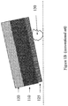
Figure 1A (conventional art) illustrates one well known deleterious side effect of epitaxial growth, known as "auto-doping." Auto doping is a process by which dopants originating from thesubstrate 110 migrate into theepitaxial layer 120, deleteriously changing the doping profile of the epitaxial layers. It is appreciated that dopant migration may take a variety of paths from a substrate to an epitaxial layer, including, for example, liberation into the process gas(ses). In general, auto doping may lead to numerous adverse effects, including, for example, reduced breakdown voltage of the epitaxial layer. Additionally, the auto doping process is generally neither controlled nor predictable. Thus, auto doping leads to numerous detrimental effects. - A wafer may have an
optional oxide seal 125 on the back side.Oxide seal 125 is generally intended to reduce auto-doping. However,oxide seal 125 may corrode and be subject to "pin-hole" defects during multiple cleaning processes between multiple epitaxial layer growth processes. Whenoxide seal 125 is subject to such corrosion, theoxide seal 125 fails to prevent auto doping. - An additional problem with epitaxial processes occurs when epitaxy undesirably grows on the back side of a wafer.
Figure 1B (conventional art) illustrates an irregular silicon "bump" ornodule 130 that has formed the back or opposite side ofwafer 110/oxide seal 125 due to exposure to process gasses. Pin-hole defects ofoxide seal 125 are prime locations for formations of such nodules, although such nodules may form at other locations, including in the absence ofoxide seal 125. Such bumps are typically not uniform. For example, such inadvertent back-side epitaxial growth does not form a unified, smooth layer, but rather forms a plurality of irregular bumps. Such nodules present an uneven wafer backside, which may interfere with many subsequent semiconductor processing steps, as they prevent accurate alignment of the wafer in processing machinery. For example, as illustrated inFigure 1B , thewafer 110 cannot lay flat due tonodule 130. - While there are many systems and methods to mitigate both auto doping and inadvertent back side epitaxial growth, including acceptance of the effects, such conventional art approaches are not acceptable in all circumstances. In addition, it is known to utilize multiple epitaxial layers. In such a circumstance, the accumulation of auto doping and/or back side nodules due to multiple epitaxial growth processes may overwhelm or otherwise find unsatisfactory conventional mitigation techniques.
-
US2007290267 describes a semiconductor device which improves the breakdown voltage of a planar-type junction edge terminating structure. The device includes an n-type semiconductor substrate layer common to an active section and an edge terminating section. An n-type drift region is formed selectively on the n-type semiconductor substrate layer in the active section and a p-type partition region is formed selectively on the n-type semiconductor substrate layer in the active section. A p-type base/body region is formed on the n-type drift region and the partition region. A source electrode is connected electrically to the p-type base/body region.; A p-type partition region is formed in the edge terminating section between the p-type base/body region and the scribe plane of the semiconductor device such that the p-type partition region in the edge terminating section surrounds the p-type base/body region. A drain electrode is connected electrically to the n-type semiconductor substrate layer. -
US2006029817 describes a wafer for epitaxial deposition that is backside sealed with a dopant seal layer (protection layer comprised of silicon dioxide or silicon nitride. A layer of polysilicon is formed coextensively over the dopant seal layer. The polysilicon layer acts as a seed layer for potentially nodule forming gasses present during epitaxial deposition. During CVD epitaxy, the epitaxial layer is deposited on the primary surface with optimal resistivity uniformity. The fugitive gasses from the epitaxial process which diffuse to the wafer periphery and backside deposit as a film on the seed layer instead of in nodules. The polysilicon layer acts as a continuous seed layer which eliminates the preferential deposition at seal layer pinholes or island seed sites.; The resulting structure of silicon substrate, dopant seal layer, polysilicon seed layer provides for nodule-free epitaxial deposition without increasing auto-doping and escalating the epitaxial resistivity non-uniformities. Alternatively, the wafer is sealed on the backside and peripheral edges with a dopant seal layer. Then, a layer of polysilicon is formed over the entire extent of the dopant seal layer. CVD epitaxy is performed, growing an epitaxial layer on the front side and depositing a film layer on the back side and peripheral edges of the wafer. The fugitive gasses from the epitaxial process which diffuse to the wafer backside and edge deposit as a film on the seed layer instead of in nodules. The amount of out-gassing is reduced because the peripheral edges of the wafer are covered with the dopant seal layer and since that layer is not exposed to the reaction gases, silicon spur and nodule formation is thwarted. -
US 5,292,679 A discloses forming a trench by lack of epitaxial growth in a masked area to fabricate a trench capacitor in a DRAM. - Broadly this writing discloses a system and method for substrate wafer back side and edge cross section seals. Systems and methods for substrate wafer back side and edge cross section seals are desired. In addition, systems and methods of forming multiple epitaxial layers without the accumulation of deleterious side effects is desired. Further, systems and methods of forming multiple epitaxial layers with vertical trenches and/or vertical doped columns are desired. Still further, systems and methods for substrate wafer back side and edge cross section seals that are compatible and complementary with conventional wafer processing systems are desired. Embodiments in accordance with the present invention provide for these needs.
- Systems and methods for substrate wafer back side and edge cross section seals are disclosed. In accordance with a first method embodiment, a method as defined in claim 1 is carried out.
- In accordance with an embodiment, additionally a layer of silicon oxide is deposited on all surfaces and edges of the silicon wafer. The silicon oxide is removed from a front surface of the silicon wafer. A layer of poly silicon is deposited on a back surface of the silicon wafer, over the silicon oxide. The epitaxial silicon is grown on the front side of the silicon wafer. Auto doping of the layer of epitaxial silicon may be reduced relative to auto doping occurring during epitaxial silicon growth on a wafer without the layer of silicon oxide.
-
-
Figure 1A (conventional art) illustrates one well known deleterious side effect of epitaxial growth, known as "auto-doping." -
Figure 1B (conventional art) illustrates an irregular silicon "bump" or nodule that has formed the back or opposite side of a wafer due to exposure to process gasses. -
Figures 2A, 2B and 2C illustrate a process of sealing a wafer substrate to prevent auto doping and/or back side nodule growth. -
Figure 3A illustrates epitaxial growth on a sealed wafer. -
Figure 3B illustrates non-uniform, e.g., selective, epitaxial growth of an epitaxial layer on the front/top surface of an epitaxial layer. -
Figure 3C illustrates repetitive doping of a plurality of epitaxial layers. -
Figure 4 illustrates a final semiconductor wafer substrate after further processing, fabricated in accordance with embodiments of the present invention. - Reference will now be made in detail to the various embodiments of the invention, examples of which are illustrated in the accompanying drawings. While the invention will be described in conjunction with these embodiments, it will be understood that they are not intended to limit the invention to these embodiments. On the contrary, the invention is defined by the appended claims. Furthermore, in the following detailed description of the present invention, numerous specific details are set forth in order to provide a thorough understanding of the present invention. However, it will be recognized by one of ordinary skill in the art that the present invention may be practiced without these specific details. In other instances, well-known methods, procedures, components, and circuits have not been described in detail as not to unnecessarily obscure aspects of the present invention.
-
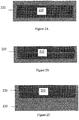
Figures 2A - 2C illustrate a process of sealing a wafer substrate to prevent auto doping and/or back side nodule growth. InFigure 2A , asilicon substrate 210 is uniformly coated withSilicon oxide 220 to a thickness of about 800 to 1200 angstroms, e.g., about 1000 angstroms.Item 210 may also comprise an oxide seal, e.g.,oxide seal 125 ofFigure 1A , on its back side. For example,Silicon oxide 220 is deposited on the front, back and edges ofwafer 210. - In
Figure 2B , the top portion ofSilicon oxide coating 220, e.g., that portion ofSilicon oxide 220 above the top or front ofwafer 210, is removed, e.g., by polishing. It is appreciated that a small amount of the top side ofwafer 210 may be removed as well. - In
Figure 2C , alayer 230 of poly Silicon is deposited on the back side ofwafer 210 over theSilicon oxide 220. For example, theSilicon oxide 220 is againstwafer 210, and thepoly silicon 230 is against theSilicon oxide 220. Thepoly Silicon 230 has a thickness of about 8000 to 9000 angstroms, e.g., about 8500 angstroms. Thepoly Silicon 230 is deposited in such a manner that it is only deposited on the back side of the wafer. One suitable process is deposition via chemical vapor deposition on a silicon carbide susceptor in a sealed wafer environment. - It is to be appreciated that the process operations illustrated in
Figures 2B and 2C may occur in a different order from that illustrated. For example, poly Silicon may be deposited on all surfaces of a wafer, and subsequently removed from the front side, for example, in conjunction with the removal of the top portion ofSilicon oxide coating 220. - The
Silicon oxide coating 220 prevents auto doping during epitaxial growth. For example,Silicon oxide coating 220 prevents migration of dopants fromwafer 210 into a process gas mixture used to form an epitaxial layer. In addition, thepoly Silicon 230 prevents the growth of non-uniform nodules on the back side ofwafer 210. For example, thepoly Silicon 230 provides uniform nucleation for epitaxial Silicon growth. Thus, while epitaxial material may still grow on the back side ofwafer 210, such growth is substantially uniform, e.g., it forms a smooth layer, in contrast to the deleterious non-uniform nodules that may form directly on the back side of an uncoated wafer, as shown inFigure 1B , as may occur under the conventional art. -
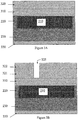
Figure 3A illustrates epitaxial growth on a sealed wafer.Wafer 210 is coated on the bottom and edges withSilicon oxide 220. The bottom ofwafer 210 is coated withpoly Silicon 230, deposited over a portion ofSilicon oxide 220. -
Epitaxial layer 310 has been grown on the front/top surface ofwafer 210. Optionally,epitaxial layer 320 has been grown on the top surface ofepitaxial layer 310. It is appreciated thatepitaxial layer 320 may have a different thickness and/or doping composition from that ofepitaxial layer 310. Due to the sealing effects ofSilicon oxide 220, no deleterious auto doping has occurred during the epitaxial growth process(es), and the epitaxial layer(s) 310, 320, beneficially have the desired doping characteristics. -
Figure 3A further illustrates a substantially uniform layer ofepitaxy 330 on the bottom side ofwafer 210.Layer 330 is formed during the growth oflayers 310 and/or 320.Layer 330 does not subject thewafer 210 to the deleterious handling effects of non-uniform silicon nodules, e.g., as shown bynodule 130 ofFigure 1B . - The epitaxial growth on the front/top surface of
wafer 210 need not be uniform.Figure 3B illustrates non-uniform, e.g., selective, epitaxial growth ofepitaxial layer 321 on the front/top surface ofepitaxial layer 310. The lack of epitaxial growth in a region has formed atrench 325. The formation oflayer 321 is well suited to a variety of well known processes for selective epitaxial growth. A region on an underlying area, e.g.,epitaxial layer 310 orsubstrate 210, in the region oftrench 325, is masked, e.g. by a dielectric film, e.g., silicon dioxide or silicon nitride, prior to epitaxial growth. - Similarly, a plurality of epitaxial layers may be growth, either uniformly, as illustrated by
layers layers trench 325 are constructed by a lack of formation of material, in contrast to processes that form such features via the removal of material. It is appreciated that the dopant concentration of each epitaxial layer may be different, so as to form a desirable doping profile. It is to be further appreciated that many epitaxial layers may be grown, of varying thickness and/or doping characteristic, such that a feature, e.g.,trench 325, may have a desirable depth. Of course,trench 325 may terminate at a substrate, e.g.,substrate 220, or within one of a plurality of epitaxial layers, e.g., 310, 321, 322, and the like. - Further, embodiments in accordance with the present invention may be combined with other methods of trench formation, e.g., methods that remove material, to form trenches that terminate within a substrate, e.g., within
substrate 220. -
Figure 3C illustrates repetitive doping of a plurality of epitaxial layers.Epitaxial layer 341 is grown, in a similar manner as illustrated by layer 320 (Figure 3A ). After formation oflayer 341, a portion oflayer 341, e.g., inregion 345, is doped by well known processes. Subsequently,epitaxial layer 342 is grown overlayer 341, and a portion oflayer 342, e.g., inregion 345, is doped by well known processes. - For example, if
substrate 210 is doped with n-type dopants,epitaxial layers Regions 345 may be doped with p-type dopants. In this novel manner, a vertical column or well of a dopant type, e.g., p-type, may be created. Since each layer is individually grown and doped, the layer thickness, depth of doping, doping concentration, doping species and the like may differ with each layer growth and doping processes. It is to be appreciated that such a column or well may have characteristics, e.g., depth and/or doping levels and/or doping profiles, that are difficult or impossible to obtain via other doping methods, e.g., conventional well implantation from above a surface. -
Figure 4 illustrates a final semiconductor wafer substrate after further processing, fabricated in accordance with embodiments of the present invention. As illustrated inFigure 4 , the depositions on the back side ofwafer 210, e.g.,epitaxy 330,poly Silicon 230 and the back side portion ofSilicon oxide 220, may be removed, e.g., via grinding or back-lapping or other well known processes, such thatwafer 210 has a desired thickness. The side/edge portions ofSilicon oxide 220 may also be removed. However, it is to be appreciated that the edges of a wafer are generally not used for a final semiconductor device, and thus removal of such edge portions ofSilicon oxide 220 may not be required. -
Figure 4 further illustratesvertical trench 325, formed by gaps in a plurality of epitaxial layers, e.g.,epitaxial layers Figure 4 illustrates a dopedcolumn 345, formed by repeating a cycle of growing a layer of epitaxial material and then doping such layer. - Embodiments in accordance with the present invention are well suited to the formation of semiconductor devices utilizing multiple epitaxial layers. For example, a trench, as utilized by well known trench semiconductors, e.g., a trench metal oxide semiconductor field effect transistor (MOSFET), may be formed by the growth of multiple, e.g., from two to 20, selectively grown epitaxial layers. Embodiments in accordance with the present invention eliminate, reduce or mitigate many deleterious effects of such multiple epitaxial growth cycles as may occur under the conventional art.
- Embodiments in accordance with the present invention are also well suited to the epitaxial growth of non-Silicon materials on Silicon substrate(s). Non-Silicon epitaxial layers may include, for example, Gallium nitride (GaN), Silicon Carbide (SiC), sapphire, Germanium (Ge), Gallium arsenide (GaAs), Indium antimonide (InSb), Lead sulfide (PbS), Lead selenide (PbSe), and the like. In order to grow such non-Silicon material(s) on top of Silicon substrates, one or more buffer layers are generally first grown on top of a Silicon substrate, forming a buffer between the Silicon substrate and the non-Silicon epitaxial layer(s). Such buffer layers are generally intended to mitigate problems between silicon substrates and non-Silicon epitaxial layers such as seeding, lattice mismatching, stress relief, cracking free, etc. Exemplary buffer layers may comprise Aluminum nitride (AlN), Patterned Sapphire (PS), Hafnium nitride (HfN), Barium fluoride (BaF2), and the like.
- Generally, high temperature (800° C - 1250° C) processing operations are needed in order to grow these buffer layers to provide good quality layers for the single crystal non-Silicon epitaxial layers. At this high temperature range (800° C - 1250° C), Silicon substrates generally out-gas Silicon and/or Arsenic from the back side and edges of the substrate during buffer layer growth (see
Figure 1A ). Such liberated gasses are deleteriously incorporated into a buffer layer (auto doping) resulting in a poor quality contaminated buffer layer. In turn, the contaminated buffer layer(s) leads to poor quality epitaxial layers disposed upon such contaminated buffer layer(s). - Embodiments in accordance with the present invention may form a seal to reduce and/or prevent such outgasing from the back and edges of a substrate during buffer layer growth. In this novel manner, high quality buffer layer(s) may be obtained, advantageously enabling high quality non-Silicon epitaxial layers to be grown on silicon substrates.
- In summary, embodiments of the present invention provide methods for substrate wafer back side and edge cross section seals. In addition, methods of forming multiple epitaxial layers without the accumulation of deleterious side effects are provided. Further, methods of forming multiple epitaxial layers with vertical trenches and vertical doped columns are provided. Still further, embodiments in accordance with the present invention provide methods for substrate wafer back side and edge cross section seals that are compatible and complementary with conventional wafer processing systems.
- Embodiments in accordance with the present technology are thus described. While the present technology has been described in particular embodiments, it should be appreciated that the present invention should not be construed as limited by such embodiments, but is defined in the below claims.
Claims (7)
- A method comprising:accessing a silicon wafer (210) of a first conductivity type;growing an epitaxial layer (360, 370) of said first conductivity type on a front surface of said silicon wafer;implanting said epitaxial layer (360, 370) to form a region (345) of an opposite conductivity type; andrepeating said growing and implanting to form a vertical column (345) of said opposite conductivity type;the method being characterized in that said method comprises masking an underlying region prior to epitaxial growth to form a trench (325) by lack of epitaxial growth.
- The method of claim 1 further comprising implanting said silicon wafer to form a region of said opposite conductivity type vertically aligned with said vertical column.
- The method of claim 1 or 2 further comprising depositing a layer of silicon oxide (220) on all surfaces of said silicon wafer (210); wherein said depositing a layer of silicon oxide (220) is performed prior to said growing; the method further comprising removing said silicon oxide (220) from a front surface of said silicon wafer (210); wherein said removing is performed prior to said growing.
- The method of claim 3 wherein said epitaxial layer is a layer of epitaxial silicon and auto doping of said layer of epitaxial silicon is reduced relative to auto doping occurring during epitaxial silicon growth on a wafer without said layer of silicon oxide.
- The method of any of claims 3 or 4 further comprising depositing a layer of polysilicon (230) on a back surface of said silicon wafer (210), over said silicon oxide (220).
- The method of claim 5 wherein said depositing a layer of polysilicon (230) is performed prior to said growing.
- The method of claim 1 further comprising growing at least six of said epitaxial layers.
Applications Claiming Priority (3)
| Application Number | Priority Date | Filing Date | Title |
|---|---|---|---|
| US23972909P | 2009-09-03 | 2009-09-03 | |
| US12/873,147 US9230810B2 (en) | 2009-09-03 | 2010-08-31 | System and method for substrate wafer back side and edge cross section seals |
| PCT/US2010/047827 WO2011029010A2 (en) | 2009-09-03 | 2010-09-03 | Method of forming a semiconductor device |
Publications (3)
| Publication Number | Publication Date |
|---|---|
| EP2474039A2 EP2474039A2 (en) | 2012-07-11 |
| EP2474039A4 EP2474039A4 (en) | 2014-01-08 |
| EP2474039B1 true EP2474039B1 (en) | 2020-11-04 |
Family
ID=43623603
Family Applications (1)
| Application Number | Title | Priority Date | Filing Date |
|---|---|---|---|
| EP10814561.6A Active EP2474039B1 (en) | 2009-09-03 | 2010-09-03 | Method of forming a semiconductor device |
Country Status (6)
| Country | Link |
|---|---|
| US (2) | US9230810B2 (en) |
| EP (1) | EP2474039B1 (en) |
| JP (1) | JP6002037B2 (en) |
| KR (2) | KR20120059559A (en) |
| CN (1) | CN102598276B (en) |
| WO (1) | WO2011029010A2 (en) |
Families Citing this family (5)
| Publication number | Priority date | Publication date | Assignee | Title |
|---|---|---|---|---|
| CN104810363B (en) * | 2014-01-26 | 2018-04-17 | 北大方正集团有限公司 | Power IC device and preparation method thereof |
| US9379185B2 (en) | 2014-04-24 | 2016-06-28 | International Business Machines Corporation | Method of forming channel region dopant control in fin field effect transistor |
| JP5928658B1 (en) * | 2014-08-07 | 2016-06-01 | ユニサンティス エレクトロニクス シンガポール プライベート リミテッドUnisantis Electronics Singapore Pte Ltd. | Semiconductor device manufacturing method and semiconductor device |
| CN106835269A (en) * | 2017-03-03 | 2017-06-13 | 上海新傲科技股份有限公司 | Laminated base plate for nitride epitaxial growth and forming method thereof |
| JP2019075438A (en) * | 2017-10-13 | 2019-05-16 | 明広 石田 | Semiconductor laser element and semiconductor laser element manufacturing method |
Citations (2)
| Publication number | Priority date | Publication date | Assignee | Title |
|---|---|---|---|---|
| US5292679A (en) * | 1992-04-23 | 1994-03-08 | Nippon Steel Corporation | Process for producing a semiconductor memory device having memory cells including transistors and capacitors |
| US9425306B2 (en) * | 2009-08-27 | 2016-08-23 | Vishay-Siliconix | Super junction trench power MOSFET devices |
Family Cites Families (93)
| Publication number | Priority date | Publication date | Assignee | Title |
|---|---|---|---|---|
| JPS5227356A (en) * | 1975-08-27 | 1977-03-01 | Nec Corp | Manufacturing process of silicon epitaxial wafer |
| US4662956A (en) | 1985-04-01 | 1987-05-05 | Motorola, Inc. | Method for prevention of autodoping of epitaxial layers |
| US4748103A (en) | 1986-03-21 | 1988-05-31 | Advanced Power Technology | Mask-surrogate semiconductor process employing dopant protective region |
| US5283201A (en) | 1988-05-17 | 1994-02-01 | Advanced Power Technology, Inc. | High density power device fabrication process |
| US20020074585A1 (en) | 1988-05-17 | 2002-06-20 | Advanced Power Technology, Inc., Delaware Corporation | Self-aligned power MOSFET with enhanced base region |
| US4922371A (en) | 1988-11-01 | 1990-05-01 | Teledyne Semiconductor | ESD protection circuit for MOS integrated circuits |
| US5055896A (en) | 1988-12-15 | 1991-10-08 | Siliconix Incorporated | Self-aligned LDD lateral DMOS transistor with high-voltage interconnect capability |
| JPH02170415A (en) | 1988-12-22 | 1990-07-02 | Masatoshi Utaka | Formation of epitaxial layer having arbitrary impurity concentration at arbitrary position |
| US5072266A (en) | 1988-12-27 | 1991-12-10 | Siliconix Incorporated | Trench DMOS power transistor with field-shaping body profile and three-dimensional geometry |
| US5416351A (en) | 1991-10-30 | 1995-05-16 | Harris Corporation | Electrostatic discharge protection |
| JPH0621388A (en) * | 1992-04-23 | 1994-01-28 | Nippon Steel Corp | Semiconductor memory and manufacture thereof |
| JP3167457B2 (en) | 1992-10-22 | 2001-05-21 | 株式会社東芝 | Semiconductor device |
| JP3311070B2 (en) | 1993-03-15 | 2002-08-05 | 株式会社東芝 | Semiconductor device |
| US5404041A (en) | 1993-03-31 | 1995-04-04 | Texas Instruments Incorporated | Source contact placement for efficient ESD/EOS protection in grounded substrate MOS integrated circuit |
| GB9306895D0 (en) | 1993-04-01 | 1993-05-26 | Philips Electronics Uk Ltd | A method of manufacturing a semiconductor device comprising an insulated gate field effect device |
| US5430315A (en) | 1993-07-22 | 1995-07-04 | Rumennik; Vladimir | Bi-directional power trench MOS field effect transistor having low on-state resistance and low leakage current |
| US5519242A (en) | 1994-08-17 | 1996-05-21 | David Sarnoff Research Center, Inc. | Electrostatic discharge protection circuit for a NMOS or lateral NPN transistor |
| JP3384899B2 (en) | 1995-01-06 | 2003-03-10 | 東芝機械株式会社 | Vapor growth method |
| US5637900A (en) | 1995-04-06 | 1997-06-10 | Industrial Technology Research Institute | Latchup-free fully-protected CMOS on-chip ESD protection circuit |
| US5567634A (en) | 1995-05-01 | 1996-10-22 | National Semiconductor Corporation | Method of fabricating self-aligned contact trench DMOS transistors |
| US6049108A (en) | 1995-06-02 | 2000-04-11 | Siliconix Incorporated | Trench-gated MOSFET with bidirectional voltage clamping |
| US6078090A (en) | 1997-04-02 | 2000-06-20 | Siliconix Incorporated | Trench-gated Schottky diode with integral clamping diode |
| EP0746030B1 (en) | 1995-06-02 | 2001-11-21 | SILICONIX Incorporated | Trench-gated power MOSFET with protective diodes in a periodically repeating pattern |
| US6140678A (en) | 1995-06-02 | 2000-10-31 | Siliconix Incorporated | Trench-gated power MOSFET with protective diode |
| US5998837A (en) | 1995-06-02 | 1999-12-07 | Siliconix Incorporated | Trench-gated power MOSFET with protective diode having adjustable breakdown voltage |
| US5661322A (en) | 1995-06-02 | 1997-08-26 | Siliconix Incorporated | Bidirectional blocking accumulation-mode trench power MOSFET |
| EP0864178A4 (en) | 1995-10-02 | 2001-10-10 | Siliconix Inc | Trench-gated mosfet including integral temperature detection diode |
| JPH09129877A (en) | 1995-10-30 | 1997-05-16 | Toyota Central Res & Dev Lab Inc | Manufacture of semiconductor device, manufacture of insulated gate semiconductor device, and insulated gate semiconductor device |
| US5637898A (en) | 1995-12-22 | 1997-06-10 | North Carolina State University | Vertical field effect transistors having improved breakdown voltage capability and low on-state resistance |
| EP0798765A3 (en) | 1996-03-28 | 1998-08-05 | Shin-Etsu Handotai Company Limited | Method of manufacturing a semiconductor wafer comprising a dopant evaporation preventive film on one main surface and an epitaxial layer on the other main surface |
| US5850095A (en) | 1996-09-24 | 1998-12-15 | Texas Instruments Incorporated | ESD protection circuit using zener diode and interdigitated NPN transistor |
| JPH10223640A (en) | 1997-02-12 | 1998-08-21 | Nec Corp | Semiconductor substrate and its manufacture |
| JP3502531B2 (en) | 1997-08-28 | 2004-03-02 | 株式会社ルネサステクノロジ | Method for manufacturing semiconductor device |
| US6268242B1 (en) | 1997-12-31 | 2001-07-31 | Richard K. Williams | Method of forming vertical mosfet device having voltage clamped gate and self-aligned contact |
| US6297531B2 (en) | 1998-01-05 | 2001-10-02 | International Business Machines Corporation | High performance, low power vertical integrated CMOS devices |
| JP3705919B2 (en) | 1998-03-05 | 2005-10-12 | 三菱電機株式会社 | Semiconductor device and manufacturing method thereof |
| US6044018A (en) | 1998-06-17 | 2000-03-28 | Mosel Vitelic, Inc. | Single-poly flash memory cell for embedded application and related methods |
| DE19839970C2 (en) * | 1998-09-02 | 2000-11-02 | Siemens Ag | Edge structure and drift area for a semiconductor component and method for their production |
| JP3413569B2 (en) | 1998-09-16 | 2003-06-03 | 株式会社日立製作所 | Insulated gate semiconductor device and method of manufacturing the same |
| KR100505619B1 (en) | 1998-09-29 | 2005-09-26 | 삼성전자주식회사 | Electro-static discharge circuit of semiconductor device, structure thereof and method for fabricating the same |
| US5998833A (en) | 1998-10-26 | 1999-12-07 | North Carolina State University | Power semiconductor devices having improved high frequency switching and breakdown characteristics |
| US6291856B1 (en) | 1998-11-12 | 2001-09-18 | Fuji Electric Co., Ltd. | Semiconductor device with alternating conductivity type layer and method of manufacturing the same |
| DE69833743T2 (en) | 1998-12-09 | 2006-11-09 | Stmicroelectronics S.R.L., Agrate Brianza | Manufacturing method of an integrated edge structure for high voltage semiconductor devices |
| US6255683B1 (en) | 1998-12-29 | 2001-07-03 | Infineon Technologies Ag | Dynamic random access memory |
| JP3743189B2 (en) | 1999-01-27 | 2006-02-08 | 富士通株式会社 | Nonvolatile semiconductor memory device and manufacturing method thereof |
| US6268639B1 (en) | 1999-02-11 | 2001-07-31 | Xilinx, Inc. | Electrostatic-discharge protection circuit |
| JP3436172B2 (en) * | 1999-03-02 | 2003-08-11 | 信越半導体株式会社 | Method for manufacturing semiconductor device |
| US6448160B1 (en) | 1999-04-01 | 2002-09-10 | Apd Semiconductor, Inc. | Method of fabricating power rectifier device to vary operating parameters and resulting device |
| US6277695B1 (en) | 1999-04-16 | 2001-08-21 | Siliconix Incorporated | Method of forming vertical planar DMOSFET with self-aligned contact |
| US6413822B2 (en) | 1999-04-22 | 2002-07-02 | Advanced Analogic Technologies, Inc. | Super-self-aligned fabrication process of trench-gate DMOS with overlying device layer |
| US6347026B1 (en) | 1999-05-26 | 2002-02-12 | Lsi Logic Corporation | Input and power protection circuit implemented in a complementary metal oxide semiconductor process using salicides |
| US6191447B1 (en) | 1999-05-28 | 2001-02-20 | Micro-Ohm Corporation | Power semiconductor devices that utilize tapered trench-based insulating regions to improve electric field profiles in highly doped drift region mesas and methods of forming same |
| US6211018B1 (en) | 1999-08-14 | 2001-04-03 | Electronics And Telecommunications Research Institute | Method for fabricating high density trench gate type power device |
| JP2001119022A (en) | 1999-10-20 | 2001-04-27 | Fuji Electric Co Ltd | Semiconductor device and manufacturing method therefor |
| JP3573674B2 (en) | 1999-12-27 | 2004-10-06 | Necエレクトロニクス株式会社 | I / O protection device for semiconductor integrated circuit and its protection method |
| US6548860B1 (en) | 2000-02-29 | 2003-04-15 | General Semiconductor, Inc. | DMOS transistor structure having improved performance |
| US6472678B1 (en) | 2000-06-16 | 2002-10-29 | General Semiconductor, Inc. | Trench MOSFET with double-diffused body profile |
| JP2002016080A (en) | 2000-06-28 | 2002-01-18 | Toshiba Corp | Manufacturing method of trench-gate type mosfet |
| US6700158B1 (en) | 2000-08-18 | 2004-03-02 | Fairchild Semiconductor Corporation | Trench corner protection for trench MOSFET |
| JP2002110978A (en) | 2000-10-02 | 2002-04-12 | Toshiba Corp | Power semiconductor element |
| US6631060B2 (en) | 2000-11-30 | 2003-10-07 | Winbond Electronics Corporation | Field oxide device with zener junction for electrostatic discharge (ESD) protection and other applications |
| JP5010774B2 (en) | 2000-12-28 | 2012-08-29 | 富士電機株式会社 | Semiconductor device manufacturing method and semiconductor device |
| US6455377B1 (en) | 2001-01-19 | 2002-09-24 | Chartered Semiconductor Manufacturing Ltd. | Method to form very high mobility vertical channel transistor by selective deposition of SiGe or multi-quantum wells (MQWs) |
| JP4932088B2 (en) | 2001-02-19 | 2012-05-16 | ルネサスエレクトロニクス株式会社 | Insulated gate type semiconductor device manufacturing method |
| US7176109B2 (en) | 2001-03-23 | 2007-02-13 | Micron Technology, Inc. | Method for forming raised structures by controlled selective epitaxial growth of facet using spacer |
| JP4826036B2 (en) * | 2001-07-16 | 2011-11-30 | 株式会社デンソー | Manufacturing method of semiconductor device |
| US6882000B2 (en) | 2001-08-10 | 2005-04-19 | Siliconix Incorporated | Trench MIS device with reduced gate-to-drain capacitance |
| US6514839B1 (en) | 2001-10-05 | 2003-02-04 | Taiwan Semiconductor Manufacturing Company | ESD implantation method in deep-submicron CMOS technology for high-voltage-tolerant applications with light-doping concentrations |
| US20030071310A1 (en) | 2001-10-11 | 2003-04-17 | Salling Craig T. | Method to increase substrate potential in MOS transistors used in ESD protection circuits |
| KR100406180B1 (en) | 2001-12-22 | 2003-11-17 | 주식회사 하이닉스반도체 | Method of manufacturing a flash memory cell |
| US6838722B2 (en) | 2002-03-22 | 2005-01-04 | Siliconix Incorporated | Structures of and methods of fabricating trench-gated MIS devices |
| US6855593B2 (en) | 2002-07-11 | 2005-02-15 | International Rectifier Corporation | Trench Schottky barrier diode |
| DE10235000B4 (en) | 2002-07-31 | 2007-01-04 | Infineon Technologies Ag | Method for forming a channel region of a transistor and NMOS transistor |
| US8629019B2 (en) | 2002-09-24 | 2014-01-14 | Vishay-Siliconix | Method of forming self aligned contacts for a power MOSFET |
| DE10346838A1 (en) * | 2002-10-08 | 2004-05-13 | International Rectifier Corp., El Segundo | Superjunction semiconductor device using spaced pylons provided with increased charge concentration at their top ends |
| US7190563B2 (en) | 2002-10-18 | 2007-03-13 | Agere Systems Inc. | Electrostatic discharge protection in a semiconductor device |
| US6800917B2 (en) | 2002-12-17 | 2004-10-05 | Texas Instruments Incorporated | Bladed silicon-on-insulator semiconductor devices and method of making |
| JP3931138B2 (en) | 2002-12-25 | 2007-06-13 | 三菱電機株式会社 | Power semiconductor device and method for manufacturing power semiconductor device |
| TW200411897A (en) | 2002-12-30 | 2004-07-01 | Winbond Electronics Corp | Robust ESD protection structures |
| US6861701B2 (en) | 2003-03-05 | 2005-03-01 | Advanced Analogic Technologies, Inc. | Trench power MOSFET with planarized gate bus |
| US6919603B2 (en) | 2003-04-30 | 2005-07-19 | Texas Instruments Incorporated | Efficient protection structure for reverse pin-to-pin electrostatic discharge |
| US7019368B1 (en) | 2003-07-11 | 2006-03-28 | Actel Corporation | Low-capacitance input/output and electrostatic discharge circuit for protecting an integrated circuit from electrostatic discharge |
| US20050036251A1 (en) | 2003-08-12 | 2005-02-17 | Micrel, Incorporated | Electrostatic discharge protection for trim-diodes |
| US7012016B2 (en) * | 2003-11-18 | 2006-03-14 | Shangjr Gwo | Method for growing group-III nitride semiconductor heterostructure on silicon substrate |
| US7250358B2 (en) * | 2004-08-06 | 2007-07-31 | Globitech Incorporated | Wafer for preventing the formation of silicon nodules and method for preventing the formation of silicon nodules |
| US20060268479A1 (en) | 2005-05-31 | 2006-11-30 | Atmel Germany Gmbh | ESD protection structure |
| US7511332B2 (en) | 2005-08-29 | 2009-03-31 | Taiwan Semiconductor Manufacturing Co., Ltd. | Vertical flash memory |
| US7544545B2 (en) | 2005-12-28 | 2009-06-09 | Vishay-Siliconix | Trench polysilicon diode |
| JP5124999B2 (en) | 2006-06-15 | 2013-01-23 | 富士電機株式会社 | Semiconductor device and manufacturing method thereof |
| TW200824003A (en) | 2006-11-17 | 2008-06-01 | Chunghwa Picture Tubes Ltd | Semiconductor device and manufacturing method thereof |
| JP4564510B2 (en) * | 2007-04-05 | 2010-10-20 | 株式会社東芝 | Power semiconductor device |
| JP2009129877A (en) | 2007-11-28 | 2009-06-11 | S Ii R:Kk | Socket for electronic component |
| JP5227356B2 (en) | 2010-03-26 | 2013-07-03 | 株式会社エヌ・ティ・ティ・ドコモ | Information terminal and information input method |
-
2010
- 2010-08-31 US US12/873,147 patent/US9230810B2/en active Active
- 2010-09-03 CN CN201080049358.3A patent/CN102598276B/en active Active
- 2010-09-03 KR KR1020127007098A patent/KR20120059559A/en not_active Application Discontinuation
- 2010-09-03 EP EP10814561.6A patent/EP2474039B1/en active Active
- 2010-09-03 KR KR1020167008584A patent/KR101752112B1/en active IP Right Grant
- 2010-09-03 JP JP2012528090A patent/JP6002037B2/en active Active
- 2010-09-03 WO PCT/US2010/047827 patent/WO2011029010A2/en active Application Filing
-
2016
- 2016-01-05 US US14/988,639 patent/US10546750B2/en active Active
Patent Citations (2)
| Publication number | Priority date | Publication date | Assignee | Title |
|---|---|---|---|---|
| US5292679A (en) * | 1992-04-23 | 1994-03-08 | Nippon Steel Corporation | Process for producing a semiconductor memory device having memory cells including transistors and capacitors |
| US9425306B2 (en) * | 2009-08-27 | 2016-08-23 | Vishay-Siliconix | Super junction trench power MOSFET devices |
Also Published As
| Publication number | Publication date |
|---|---|
| JP6002037B2 (en) | 2016-10-05 |
| CN102598276A (en) | 2012-07-18 |
| KR101752112B1 (en) | 2017-06-28 |
| KR20120059559A (en) | 2012-06-08 |
| US9230810B2 (en) | 2016-01-05 |
| WO2011029010A3 (en) | 2011-07-21 |
| CN102598276B (en) | 2015-05-06 |
| WO2011029010A2 (en) | 2011-03-10 |
| EP2474039A4 (en) | 2014-01-08 |
| EP2474039A2 (en) | 2012-07-11 |
| US20110049682A1 (en) | 2011-03-03 |
| JP2013504217A (en) | 2013-02-04 |
| KR20160042462A (en) | 2016-04-19 |
| US10546750B2 (en) | 2020-01-28 |
| US20160225622A1 (en) | 2016-08-04 |
Similar Documents
| Publication | Publication Date | Title |
|---|---|---|
| US10510589B2 (en) | Cyclic conformal deposition/anneal/etch for Si gapfill | |
| KR101548013B1 (en) | Stressor for engineered strain on channel | |
| KR101160930B1 (en) | Methods of forming carbon-containing silicon epitaxial layers | |
| US10546750B2 (en) | System and method for substrate wafer back side and edge cross section seals | |
| US8710632B2 (en) | Compound semiconductor epitaxial structure and method for fabricating the same | |
| WO2004082003A2 (en) | Apparatuses and methods for forming a substantially facet-free epitaxial film | |
| KR20090037424A (en) | Selective epitaxial formation of semiconductor films | |
| CN103311279A (en) | Semiconductor device and method for manufacturing the semiconductor device | |
| US8012858B2 (en) | Method of fabricating semiconductor device | |
| US20240087961A1 (en) | Fin Loss Prevention | |
| US10312096B2 (en) | Methods for titanium silicide formation using TiCl4 precursor and silicon-containing precursor | |
| US8102052B2 (en) | Process for the simultaneous deposition of crystalline and amorphous layers with doping | |
| EP4098783B1 (en) | Buffer layer on silicon carbide substrate, and method for forming buffer layer | |
| KR950002173B1 (en) | Polisilicon deposition method of semiconductor device | |
| US10796915B2 (en) | Method for forming epitaxial layer at low temperature | |
| KR102417484B1 (en) | Epitaxial wafer and method for fabricating the same | |
| KR20180034052A (en) | Apparatus and method for manufacturing epitaxial wafer | |
| KR20190026472A (en) | Epitaxial wafer and method for fabricating the same |
Legal Events
| Date | Code | Title | Description |
|---|---|---|---|
| PUAI | Public reference made under article 153(3) epc to a published international application that has entered the european phase |
Free format text: ORIGINAL CODE: 0009012 |
|
| 17P | Request for examination filed |
Effective date: 20120329 |
|
| AK | Designated contracting states |
Kind code of ref document: A2 Designated state(s): AL AT BE BG CH CY CZ DE DK EE ES FI FR GB GR HR HU IE IS IT LI LT LU LV MC MK MT NL NO PL PT RO SE SI SK SM TR |
|
| DAX | Request for extension of the european patent (deleted) | ||
| A4 | Supplementary search report drawn up and despatched |
Effective date: 20131205 |
|
| RIC1 | Information provided on ipc code assigned before grant |
Ipc: H01L 21/336 20060101ALI20131129BHEP Ipc: H01L 29/78 20060101AFI20131129BHEP Ipc: H01L 21/20 20060101ALI20131129BHEP |
|
| STAA | Information on the status of an ep patent application or granted ep patent |
Free format text: STATUS: EXAMINATION IS IN PROGRESS |
|
| 17Q | First examination report despatched |
Effective date: 20170519 |
|
| GRAP | Despatch of communication of intention to grant a patent |
Free format text: ORIGINAL CODE: EPIDOSNIGR1 |
|
| STAA | Information on the status of an ep patent application or granted ep patent |
Free format text: STATUS: GRANT OF PATENT IS INTENDED |
|
| INTG | Intention to grant announced |
Effective date: 20200406 |
|
| GRAS | Grant fee paid |
Free format text: ORIGINAL CODE: EPIDOSNIGR3 |
|
| GRAA | (expected) grant |
Free format text: ORIGINAL CODE: 0009210 |
|
| STAA | Information on the status of an ep patent application or granted ep patent |
Free format text: STATUS: THE PATENT HAS BEEN GRANTED |
|
| AK | Designated contracting states |
Kind code of ref document: B1 Designated state(s): AL AT BE BG CH CY CZ DE DK EE ES FI FR GB GR HR HU IE IS IT LI LT LU LV MC MK MT NL NO PL PT RO SE SI SK SM TR |
|
| REG | Reference to a national code |
Ref country code: GB Ref legal event code: FG4D |
|
| REG | Reference to a national code |
Ref country code: CH Ref legal event code: EP |
|
| REG | Reference to a national code |
Ref country code: AT Ref legal event code: REF Ref document number: 1331941 Country of ref document: AT Kind code of ref document: T Effective date: 20201115 |
|
| REG | Reference to a national code |
Ref country code: DE Ref legal event code: R096 Ref document number: 602010065847 Country of ref document: DE |
|
| REG | Reference to a national code |
Ref country code: IE Ref legal event code: FG4D |
|
| REG | Reference to a national code |
Ref country code: NL Ref legal event code: MP Effective date: 20201104 |
|
| REG | Reference to a national code |
Ref country code: AT Ref legal event code: MK05 Ref document number: 1331941 Country of ref document: AT Kind code of ref document: T Effective date: 20201104 |
|
| PG25 | Lapsed in a contracting state [announced via postgrant information from national office to epo] |
Ref country code: FI Free format text: LAPSE BECAUSE OF FAILURE TO SUBMIT A TRANSLATION OF THE DESCRIPTION OR TO PAY THE FEE WITHIN THE PRESCRIBED TIME-LIMIT Effective date: 20201104 Ref country code: NO Free format text: LAPSE BECAUSE OF FAILURE TO SUBMIT A TRANSLATION OF THE DESCRIPTION OR TO PAY THE FEE WITHIN THE PRESCRIBED TIME-LIMIT Effective date: 20210204 Ref country code: PT Free format text: LAPSE BECAUSE OF FAILURE TO SUBMIT A TRANSLATION OF THE DESCRIPTION OR TO PAY THE FEE WITHIN THE PRESCRIBED TIME-LIMIT Effective date: 20210304 Ref country code: GR Free format text: LAPSE BECAUSE OF FAILURE TO SUBMIT A TRANSLATION OF THE DESCRIPTION OR TO PAY THE FEE WITHIN THE PRESCRIBED TIME-LIMIT Effective date: 20210205 |
|
| PG25 | Lapsed in a contracting state [announced via postgrant information from national office to epo] |
Ref country code: PL Free format text: LAPSE BECAUSE OF FAILURE TO SUBMIT A TRANSLATION OF THE DESCRIPTION OR TO PAY THE FEE WITHIN THE PRESCRIBED TIME-LIMIT Effective date: 20201104 Ref country code: SE Free format text: LAPSE BECAUSE OF FAILURE TO SUBMIT A TRANSLATION OF THE DESCRIPTION OR TO PAY THE FEE WITHIN THE PRESCRIBED TIME-LIMIT Effective date: 20201104 Ref country code: LV Free format text: LAPSE BECAUSE OF FAILURE TO SUBMIT A TRANSLATION OF THE DESCRIPTION OR TO PAY THE FEE WITHIN THE PRESCRIBED TIME-LIMIT Effective date: 20201104 Ref country code: BG Free format text: LAPSE BECAUSE OF FAILURE TO SUBMIT A TRANSLATION OF THE DESCRIPTION OR TO PAY THE FEE WITHIN THE PRESCRIBED TIME-LIMIT Effective date: 20210204 Ref country code: AT Free format text: LAPSE BECAUSE OF FAILURE TO SUBMIT A TRANSLATION OF THE DESCRIPTION OR TO PAY THE FEE WITHIN THE PRESCRIBED TIME-LIMIT Effective date: 20201104 Ref country code: IS Free format text: LAPSE BECAUSE OF FAILURE TO SUBMIT A TRANSLATION OF THE DESCRIPTION OR TO PAY THE FEE WITHIN THE PRESCRIBED TIME-LIMIT Effective date: 20210304 Ref country code: ES Free format text: LAPSE BECAUSE OF FAILURE TO SUBMIT A TRANSLATION OF THE DESCRIPTION OR TO PAY THE FEE WITHIN THE PRESCRIBED TIME-LIMIT Effective date: 20201104 |
|
| REG | Reference to a national code |
Ref country code: LT Ref legal event code: MG9D |
|
| PG25 | Lapsed in a contracting state [announced via postgrant information from national office to epo] |
Ref country code: HR Free format text: LAPSE BECAUSE OF FAILURE TO SUBMIT A TRANSLATION OF THE DESCRIPTION OR TO PAY THE FEE WITHIN THE PRESCRIBED TIME-LIMIT Effective date: 20201104 |
|
| PG25 | Lapsed in a contracting state [announced via postgrant information from national office to epo] |
Ref country code: LT Free format text: LAPSE BECAUSE OF FAILURE TO SUBMIT A TRANSLATION OF THE DESCRIPTION OR TO PAY THE FEE WITHIN THE PRESCRIBED TIME-LIMIT Effective date: 20201104 Ref country code: EE Free format text: LAPSE BECAUSE OF FAILURE TO SUBMIT A TRANSLATION OF THE DESCRIPTION OR TO PAY THE FEE WITHIN THE PRESCRIBED TIME-LIMIT Effective date: 20201104 Ref country code: CZ Free format text: LAPSE BECAUSE OF FAILURE TO SUBMIT A TRANSLATION OF THE DESCRIPTION OR TO PAY THE FEE WITHIN THE PRESCRIBED TIME-LIMIT Effective date: 20201104 Ref country code: SM Free format text: LAPSE BECAUSE OF FAILURE TO SUBMIT A TRANSLATION OF THE DESCRIPTION OR TO PAY THE FEE WITHIN THE PRESCRIBED TIME-LIMIT Effective date: 20201104 Ref country code: RO Free format text: LAPSE BECAUSE OF FAILURE TO SUBMIT A TRANSLATION OF THE DESCRIPTION OR TO PAY THE FEE WITHIN THE PRESCRIBED TIME-LIMIT Effective date: 20201104 Ref country code: SK Free format text: LAPSE BECAUSE OF FAILURE TO SUBMIT A TRANSLATION OF THE DESCRIPTION OR TO PAY THE FEE WITHIN THE PRESCRIBED TIME-LIMIT Effective date: 20201104 |
|
| REG | Reference to a national code |
Ref country code: DE Ref legal event code: R097 Ref document number: 602010065847 Country of ref document: DE |
|
| PG25 | Lapsed in a contracting state [announced via postgrant information from national office to epo] |
Ref country code: DK Free format text: LAPSE BECAUSE OF FAILURE TO SUBMIT A TRANSLATION OF THE DESCRIPTION OR TO PAY THE FEE WITHIN THE PRESCRIBED TIME-LIMIT Effective date: 20201104 |
|
| PLBE | No opposition filed within time limit |
Free format text: ORIGINAL CODE: 0009261 |
|
| STAA | Information on the status of an ep patent application or granted ep patent |
Free format text: STATUS: NO OPPOSITION FILED WITHIN TIME LIMIT |
|
| 26N | No opposition filed |
Effective date: 20210805 |
|
| PG25 | Lapsed in a contracting state [announced via postgrant information from national office to epo] |
Ref country code: NL Free format text: LAPSE BECAUSE OF FAILURE TO SUBMIT A TRANSLATION OF THE DESCRIPTION OR TO PAY THE FEE WITHIN THE PRESCRIBED TIME-LIMIT Effective date: 20201104 Ref country code: IT Free format text: LAPSE BECAUSE OF FAILURE TO SUBMIT A TRANSLATION OF THE DESCRIPTION OR TO PAY THE FEE WITHIN THE PRESCRIBED TIME-LIMIT Effective date: 20201104 Ref country code: AL Free format text: LAPSE BECAUSE OF FAILURE TO SUBMIT A TRANSLATION OF THE DESCRIPTION OR TO PAY THE FEE WITHIN THE PRESCRIBED TIME-LIMIT Effective date: 20201104 |
|
| PG25 | Lapsed in a contracting state [announced via postgrant information from national office to epo] |
Ref country code: SI Free format text: LAPSE BECAUSE OF FAILURE TO SUBMIT A TRANSLATION OF THE DESCRIPTION OR TO PAY THE FEE WITHIN THE PRESCRIBED TIME-LIMIT Effective date: 20201104 |
|
| REG | Reference to a national code |
Ref country code: CH Ref legal event code: PL |
|
| REG | Reference to a national code |
Ref country code: BE Ref legal event code: MM Effective date: 20210930 |
|
| PG25 | Lapsed in a contracting state [announced via postgrant information from national office to epo] |
Ref country code: IS Free format text: LAPSE BECAUSE OF FAILURE TO SUBMIT A TRANSLATION OF THE DESCRIPTION OR TO PAY THE FEE WITHIN THE PRESCRIBED TIME-LIMIT Effective date: 20210304 Ref country code: MC Free format text: LAPSE BECAUSE OF FAILURE TO SUBMIT A TRANSLATION OF THE DESCRIPTION OR TO PAY THE FEE WITHIN THE PRESCRIBED TIME-LIMIT Effective date: 20201104 |
|
| PG25 | Lapsed in a contracting state [announced via postgrant information from national office to epo] |
Ref country code: LU Free format text: LAPSE BECAUSE OF NON-PAYMENT OF DUE FEES Effective date: 20210903 Ref country code: IE Free format text: LAPSE BECAUSE OF NON-PAYMENT OF DUE FEES Effective date: 20210903 Ref country code: BE Free format text: LAPSE BECAUSE OF NON-PAYMENT OF DUE FEES Effective date: 20210930 |
|
| PG25 | Lapsed in a contracting state [announced via postgrant information from national office to epo] |
Ref country code: LI Free format text: LAPSE BECAUSE OF NON-PAYMENT OF DUE FEES Effective date: 20210930 Ref country code: CH Free format text: LAPSE BECAUSE OF NON-PAYMENT OF DUE FEES Effective date: 20210930 |
|
| PG25 | Lapsed in a contracting state [announced via postgrant information from national office to epo] |
Ref country code: HU Free format text: LAPSE BECAUSE OF FAILURE TO SUBMIT A TRANSLATION OF THE DESCRIPTION OR TO PAY THE FEE WITHIN THE PRESCRIBED TIME-LIMIT; INVALID AB INITIO Effective date: 20100903 Ref country code: CY Free format text: LAPSE BECAUSE OF FAILURE TO SUBMIT A TRANSLATION OF THE DESCRIPTION OR TO PAY THE FEE WITHIN THE PRESCRIBED TIME-LIMIT Effective date: 20201104 |
|
| PGFP | Annual fee paid to national office [announced via postgrant information from national office to epo] |
Ref country code: GB Payment date: 20230927 Year of fee payment: 14 |
|
| PGFP | Annual fee paid to national office [announced via postgrant information from national office to epo] |
Ref country code: FR Payment date: 20230925 Year of fee payment: 14 Ref country code: DE Payment date: 20230927 Year of fee payment: 14 |