EP2472292B1 - Objekterkennungsvorrichtung und damit ausgestattetes beleuchtungssystem - Google Patents
Objekterkennungsvorrichtung und damit ausgestattetes beleuchtungssystem Download PDFInfo
- Publication number
- EP2472292B1 EP2472292B1 EP10811684.9A EP10811684A EP2472292B1 EP 2472292 B1 EP2472292 B1 EP 2472292B1 EP 10811684 A EP10811684 A EP 10811684A EP 2472292 B1 EP2472292 B1 EP 2472292B1
- Authority
- EP
- European Patent Office
- Prior art keywords
- sensor
- frequency
- detection
- noise
- target object
- Prior art date
- Legal status (The legal status is an assumption and is not a legal conclusion. Google has not performed a legal analysis and makes no representation as to the accuracy of the status listed.)
- Not-in-force
Links
- 238000001514 detection method Methods 0.000 title claims description 165
- 238000005286 illumination Methods 0.000 title claims description 16
- 230000002159 abnormal effect Effects 0.000 description 8
- 230000035945 sensitivity Effects 0.000 description 8
- 238000004458 analytical method Methods 0.000 description 6
- 230000007423 decrease Effects 0.000 description 6
- 230000003321 amplification Effects 0.000 description 2
- 238000009434 installation Methods 0.000 description 2
- 238000012544 monitoring process Methods 0.000 description 2
- 238000003199 nucleic acid amplification method Methods 0.000 description 2
- 238000006243 chemical reaction Methods 0.000 description 1
- 230000003247 decreasing effect Effects 0.000 description 1
- 230000001419 dependent effect Effects 0.000 description 1
- 238000010586 diagram Methods 0.000 description 1
- 230000000694 effects Effects 0.000 description 1
- 238000004134 energy conservation Methods 0.000 description 1
Images


Classifications
-
- G—PHYSICS
- G01—MEASURING; TESTING
- G01S—RADIO DIRECTION-FINDING; RADIO NAVIGATION; DETERMINING DISTANCE OR VELOCITY BY USE OF RADIO WAVES; LOCATING OR PRESENCE-DETECTING BY USE OF THE REFLECTION OR RERADIATION OF RADIO WAVES; ANALOGOUS ARRANGEMENTS USING OTHER WAVES
- G01S13/00—Systems using the reflection or reradiation of radio waves, e.g. radar systems; Analogous systems using reflection or reradiation of waves whose nature or wavelength is irrelevant or unspecified
- G01S13/02—Systems using reflection of radio waves, e.g. primary radar systems; Analogous systems
- G01S13/50—Systems of measurement based on relative movement of target
- G01S13/52—Discriminating between fixed and moving objects or between objects moving at different speeds
- G01S13/56—Discriminating between fixed and moving objects or between objects moving at different speeds for presence detection
-
- G—PHYSICS
- G01—MEASURING; TESTING
- G01S—RADIO DIRECTION-FINDING; RADIO NAVIGATION; DETERMINING DISTANCE OR VELOCITY BY USE OF RADIO WAVES; LOCATING OR PRESENCE-DETECTING BY USE OF THE REFLECTION OR RERADIATION OF RADIO WAVES; ANALOGOUS ARRANGEMENTS USING OTHER WAVES
- G01S15/00—Systems using the reflection or reradiation of acoustic waves, e.g. sonar systems
- G01S15/02—Systems using the reflection or reradiation of acoustic waves, e.g. sonar systems using reflection of acoustic waves
- G01S15/50—Systems of measurement, based on relative movement of the target
- G01S15/52—Discriminating between fixed and moving objects or between objects moving at different speeds
- G01S15/523—Discriminating between fixed and moving objects or between objects moving at different speeds for presence detection
-
- G—PHYSICS
- G01—MEASURING; TESTING
- G01S—RADIO DIRECTION-FINDING; RADIO NAVIGATION; DETERMINING DISTANCE OR VELOCITY BY USE OF RADIO WAVES; LOCATING OR PRESENCE-DETECTING BY USE OF THE REFLECTION OR RERADIATION OF RADIO WAVES; ANALOGOUS ARRANGEMENTS USING OTHER WAVES
- G01S17/00—Systems using the reflection or reradiation of electromagnetic waves other than radio waves, e.g. lidar systems
- G01S17/02—Systems using the reflection of electromagnetic waves other than radio waves
- G01S17/50—Systems of measurement based on relative movement of target
-
- G—PHYSICS
- G01—MEASURING; TESTING
- G01S—RADIO DIRECTION-FINDING; RADIO NAVIGATION; DETERMINING DISTANCE OR VELOCITY BY USE OF RADIO WAVES; LOCATING OR PRESENCE-DETECTING BY USE OF THE REFLECTION OR RERADIATION OF RADIO WAVES; ANALOGOUS ARRANGEMENTS USING OTHER WAVES
- G01S7/00—Details of systems according to groups G01S13/00, G01S15/00, G01S17/00
- G01S7/02—Details of systems according to groups G01S13/00, G01S15/00, G01S17/00 of systems according to group G01S13/00
- G01S7/023—Interference mitigation, e.g. reducing or avoiding non-intentional interference with other HF-transmitters, base station transmitters for mobile communication or other radar systems, e.g. using electro-magnetic interference [EMI] reduction techniques
- G01S7/0232—Avoidance by frequency multiplex
-
- G—PHYSICS
- G01—MEASURING; TESTING
- G01S—RADIO DIRECTION-FINDING; RADIO NAVIGATION; DETERMINING DISTANCE OR VELOCITY BY USE OF RADIO WAVES; LOCATING OR PRESENCE-DETECTING BY USE OF THE REFLECTION OR RERADIATION OF RADIO WAVES; ANALOGOUS ARRANGEMENTS USING OTHER WAVES
- G01S7/00—Details of systems according to groups G01S13/00, G01S15/00, G01S17/00
- G01S7/02—Details of systems according to groups G01S13/00, G01S15/00, G01S17/00 of systems according to group G01S13/00
- G01S7/28—Details of pulse systems
- G01S7/285—Receivers
- G01S7/292—Extracting wanted echo-signals
- G01S7/2921—Extracting wanted echo-signals based on data belonging to one radar period
- G01S7/2922—Extracting wanted echo-signals based on data belonging to one radar period by using a controlled threshold
-
- H—ELECTRICITY
- H05—ELECTRIC TECHNIQUES NOT OTHERWISE PROVIDED FOR
- H05B—ELECTRIC HEATING; ELECTRIC LIGHT SOURCES NOT OTHERWISE PROVIDED FOR; CIRCUIT ARRANGEMENTS FOR ELECTRIC LIGHT SOURCES, IN GENERAL
- H05B47/00—Circuit arrangements for operating light sources in general, i.e. where the type of light source is not relevant
- H05B47/10—Controlling the light source
- H05B47/105—Controlling the light source in response to determined parameters
- H05B47/115—Controlling the light source in response to determined parameters by determining the presence or movement of objects or living beings
-
- Y—GENERAL TAGGING OF NEW TECHNOLOGICAL DEVELOPMENTS; GENERAL TAGGING OF CROSS-SECTIONAL TECHNOLOGIES SPANNING OVER SEVERAL SECTIONS OF THE IPC; TECHNICAL SUBJECTS COVERED BY FORMER USPC CROSS-REFERENCE ART COLLECTIONS [XRACs] AND DIGESTS
- Y02—TECHNOLOGIES OR APPLICATIONS FOR MITIGATION OR ADAPTATION AGAINST CLIMATE CHANGE
- Y02B—CLIMATE CHANGE MITIGATION TECHNOLOGIES RELATED TO BUILDINGS, e.g. HOUSING, HOUSE APPLIANCES OR RELATED END-USER APPLICATIONS
- Y02B20/00—Energy efficient lighting technologies, e.g. halogen lamps or gas discharge lamps
- Y02B20/40—Control techniques providing energy savings, e.g. smart controller or presence detection
Definitions
- the invention relates generally to object detection devices and illumination systems provided therewith and, more particularly, to an object detection device comprising a sensor, which detects the presence or absence of a detection target object in a detection area and outputs a sensor signal, and an illumination system provided therewith.
- an illumination system which comprises a lighting apparatus and an object detection device comprising a sensor (a motion sensor). Then, the illumination system detects the presence or absence of a detection target object (e.g., a person) in a predetermined detection area via the object detection device, and activates the lighting apparatus during a predetermined time period upon detecting the presence.
- a detection target object e.g., a person
- the illumination system can activate or deactivate the lighting apparatus automatically, and can prevent a user from forgetting to turn the lighting apparatus off and then can improve convenience and energy conservation.
- the illumination system is generally used in locations, such as stairs and passages of establishments, where it is necessary to activate the lighting apparatus to ensure security of a passerby, and where there is no problem if the lighting apparatus is activated only when there is the passerby.
- a PIR (Passive Infrared Ray) sensor mainly has been used for the object detection device.
- the PIR sensor is a passive type sensor, and senses temperature variations caused by a person's motion in a detection area, and outputs a sensor signal. This sensor is relatively cheap and can be used easily.
- the above illumination system with the sensor is installed in a location, such as a high ceiling in a factory, a distance from the sensor to the detection target object increases. Therefore, it is difficult to use the PIR sensor having a relatively short sensing distance. So, an active sensor having a relatively long sensing distance is used in such a location.
- the active sensor itself transmits a detection wave such as an electromagnetic wave, and then receives the detection wave reflected by the detection target object, and thereby detects the presence or absence of the detection target object in the detection area
- the active sensor includes a millimeter-wave sensor which transmits a millimeter wave as the detection wave and a distance measuring sensor.
- the millimeter-wave sensor comprises a Doppler sensor.
- the Doppler sensor transmits the millimeter wave to the detection area, and then receives the millimeter wave reflected by the detection target object moving in the detection area, and then outputs a sensor signal having a frequency, which is equivalent to a frequency difference between the transmitted millimeter wave and the received millimeter wave.
- the object detection device comprising the sensor determines the presence or absence of object moving in the detection area, based on the sensor signal outputted from the sensor, and controls to a lighting state of the lighting apparatus (e.g., see Japanese Patent Application Laid-Open No. 2009-168778 ).
- EP 1 683 693 A1 discloses a periphery monitoring system for monitoring movements of a mobile object around an installation location of a Doppler sensor 1.
- a signal output from the Doppler sensor 1 is subjected to an FFT analysis, and a total sum of the frequency levels of all of the frequency bands obtained through the FFT analysis is calculated at predetermined time intervals.
- a reference level and abnormal level are set based on the calculated total sum.
- the periphery status is determined to be abnormal. If the total sum exceeds the abnormal level but does not fall to or below the abnormal level even after the first set period passes since the exceeding of the abnormal level, the periphery status is determined to be normal, and the reference level is updated to a new reference level set based on total sums calculated during the first set period.
- the noise decreases a signal-to-noise ratio of the object detection device. Therefore, there is a problem that the sensor signal is buried in the noise and the object detection device can not detect the sensor signal, and thus sensitivity of detection decreases.
- An object detection device of the present invention comprises an active sensor, a signal processor, a determining unit, a frequency analyzer and a noise rejection unit. Then, said active sensor transmits a detection wave to a predetermined detection area, and receives the detection wave reflected by a detection target object, and thereby detects the presence or absence of the detection target object in the predetermined detection area, and outputs a sensor signal.
- said signal processor divides the sensor signal outputted from said active sensor (10) with respect to a plurality of frequency bands, and outputs the sensor signals with respect to each predetermined frequency band, and then said determining unit determines the presence or absence of the detection target object by comparing the divided sensor signals output from said signal processor with a plurality of predetermined threshold values, respectively, wherein the plurality of predetermined threshold values are defined with respect to the plurality of frequency bands, respectively.
- said frequency analyzer detects a signal intensity of individual frequencies of the sensor signal output from the active sensor (10) spaced apart from each other in 1 [Hz] units.
- said noise rejection unit causes said determining unit to invalidate, from among said plurality of frequency bands, a frequency band including a noise of a particular frequency having signal intensity greater than or equal to a defined value, when the noise of the particular frequency is detected constantly from the signal intensity of said particular frequency output from said frequency analyzer.
- said noise rejection unit causes said determining unit to invalidate a frequency band including a noise of a particular frequency having intensity greater than or equal to a defined value, when the noise of the particular frequency is detected constantly from an output of said frequency analyzer.
- said signal processor comprises an amplifying circuit having a plurality of amplifiers, and then said plurality of amplifiers divide and amplify the sensor signal with respect to each of a plurality of frequency bands to output to said determining unit.
- said plurality of amplifiers divide and amplify the sensor signal with respect to each of a plurality of frequency bands to output to said determining unit, and thus said determining unit can determine the presence or absence of the detection target object from the plurality of frequency bands of the sensor signal received at the same timing.
- said active sensor is a Doppler sensor using a radio wave as the detection wave, and then said Doppler sensor is configured to output the sensor signal having a frequency which is equivalent to a frequency difference between the detection wave transmitted to the detection area and the detection wave reflected by the detection target object moving in the detection area.
- said active sensor is a Doppler sensor, and thus the object detection device can detect the presence or absence of the detection target object moving in the detection area, and a stationary target object in a fixed position can be excluded from a detection target.
- the sensor signal outputted from said active sensor includes a frequency at least depending on a size of the detection target object and having a width greater than or equal to a predetermined width, when said active sensor detects the presence of the detection target object. Then, a band width of a frequency band outputted from said signal processor is defined to be narrower than the predetermined width.
- said noise rejection unit invalidates a frequency band including the noise, all signal components of the sensor signal are not invalidated by said noise rejection unit. Therefore, said determining unit can determine the presence or absence of the detection target object.
- said determining unit is configured to define the predetermined threshold value with respect to each of frequency bands outputted from said signal processor. Further, said determining unit is configured to redefine the predetermined threshold value according to the surrounding environment in stable state, where a variation width of intensity of the sensor signal detected by said frequency analyzer is within a defined range during a predetermined time period. In this configuration, when a variation width of an intensity of the sensor signal remains stable state during a predetermined time period, said determining unit redefines the predetermined threshold value according to the surrounding environment.
- the object detection device can detect the presence or absence of the detection target object with most suitable sensitivity according to the surrounding environment.
- an illumination system comprises the above-mentioned object detection device and a lighting apparatus connected to the object detection device.
- the object detection device comprises a lighting controller, and said lighting controller controls a lighting state of said lighting apparatus to activate said lighting apparatus, when detecting the presence of the detection target object.
- the illumination system can decrease the influence of a noise of a particular frequency produced constantly and can improve sensitivity of detection. Thus, even if the sensor signal is buried in the noise, the illumination system can detect the presence of the detection target object and can activate said lighting apparatus.
- an illumination system of the present embodiment comprises an object detection device 1 provided with a sensor 10 detecting the presence or absence of a detection target object in a detection area A1 and outputting a sensor signal, and a lighting apparatus 2 connected to the object detection device 1.
- the object detection device 1 controls a lighting state of the lighting apparatus 2.
- the object detection device 1 and the lighting apparatus 2 are installed adjacent to each other to a ceiling C1 located above the detection area A1.
- the detection area A1 is formed into a conically-shape of which a top is located in the sensor 10.
- the sensor 10 of the object detection device 1 is active sensor 10. Then, the active sensor 10 itself transmits a detection wave, such as an electromagnetic wave, to the detection area A1, and receives the detection wave reflected by the detection target object, and thereby detects the presence or absence of the detection target object in the detection area A1.
- a millimeter-wave sensor (a Doppler sensor) is used as the active sensor 10, and transmits a millimeter wave of 24.15 [GHz] to the detection area A1, and receives the millimeter wave reflected by the detection target object moving in the detection area A1, and outputs a sensor signal having a Doppler frequency which is equivalent to a frequency difference between the transmitted millimeter wave and the received millimeter wave.
- the sensor 10 detects the presence or absence of the object moving in the detection area A1 by using the shift of the frequency.
- the object detection device 1 comprises an amplifying circuit 11, a determining unit 12 and a lighting controller 13 in addition to the above-mentioned sensor 10. Then, the amplifying circuit 11 is configured to divide the sensor signal outputted from the sensor 10 with respect to each of a plurality of frequency bands and to amplify the sensor signal with respect to each of the plurality of frequency bands, and the determining unit 12 determines the presence or absence of the detection target object by comparing an output of the amplifying circuit 11 with a predetermined threshold value, and the lighting controller 13 controls a lighting state of a light source 3 of the lighting apparatus 2 according to a determination result in the determining unit 12.
- the object detection device 1 of the present embodiment comprises a frequency analyzer 14 and a noise rejection unit 22 (a noise determining unit 15 and a switching circuit 16).
- the frequency analyzer 14 detects intensity of each frequency of the sensor signal outputted from the sensor 10, and the noise rejection unit 22 decreases the influence of a noise of a particular frequency produced constantly by using an analysis result in the frequency analyzer 14.
- a FFT (fast Fourier transform) analyzer is used as the frequency analyzer 14, and analyzes every 0.2 [sec].
- the determining unit 12, the lighting controller 13 and the noise rejection unit 22 are included in a control block 17 mainly comprising a microcomputer.
- the amplifying circuit 11 constitutes a signal processor outputting the sensor signal with respect to each of predetermined frequency bands.
- a FFT analyzer and a digital filter may constitute the signal processor.
- the amplifying circuit 11 has a plurality of amplifiers 18, and an operational amplifier is used as each amplifier 18. Then, in each amplifier 18, a frequency band of a signal, being subject for amplifying, can be set by an adjustment of various parameters of a circuit constituting the amplifier 18. That is, each amplifier 18 also functions as a bandpass filter permitting the passage of a signal of a particular frequency. Then, in the amplifying circuit 11, the plurality of amplifiers 18 are connected in parallel, and then divide and amplify the sensor signal with respect to each of a plurality of frequency bands. Then, each amplifier 18 outputs a divided and amplified signal having the corresponding frequency band, individually. In this way, the amplifying circuit 11 amplifies the small sensor signal, and thus the subsequent determining unit 12 can handle determination of the sensor signal easily.
- the determining unit 12 requires to receive the sensor signal having a frequency band of about 0 to 160 [Hz] in order to detect the detection target object M1.
- the amplifying circuit 11 of the present embodiment is configured to divide a frequency band of 0 to 200 [Hz] into a plurality of frequency bands, and thereby each of the plurality of frequency bands is narrower than the bandwidth (40 to 50 [Hz]) of the sensor signal outputted upon detection of the detection target object M1.
- the amplifying circuit 11 sets a plurality of frequency bands (hereinafter, called "band pass”), being subject to signal amplification in the plurality of amplifiers 18, into 0 to 10 [Hz], 10 to 20 [Hz], 20 to 30 [Hz], ..., 190 to 200 [Hz], respectively, so as to divide a frequency band of 0 to 200 [Hz] at 10 [Hz] intervals, and thus the plurality of frequency bands do not overlap with each other.
- band pass a plurality of frequency bands
- the determining unit 12 comprises a comparator 19 with respect to each amplifier 18. Then, each comparator 19 converts an output of the corresponding amplifier 18 into a digital value as A/D conversion, and then compares the digital value with a predetermined threshold value, and thereby the determining unit 12 determines the presence or absence of the detection target object M1.
- the threshold value is set with respect to each band pass (that is, each amplifier 18), individually, and each comparator 19 outputs a high-level signal when the output of the corresponding amplifier 18 is outside the scope of the threshold value.
- the determining unit 12 comprises an OR circuit 20, which obtains a logical add of a comparison result from each comparator 19.
- the OR circuit 20 outputs a sensing signal showing "sensed condition” which means the presence of the detection target object M1. In contrast, if all signals are low-level, the OR circuit 20 outputs a sensing signal showing "non-sensed condition” which means the absence of the detection target object M1. The sensing signal shows "1" in the sensed condition, and shows "0" in the non-sensed condition.
- the lighting controller 13 receives the sensing signal outputted from the determining unit 12, and then generates a control signal to transmit to the lighting apparatus 2.
- the sensing signal outputted from the determining unit 12 shows "1" (the sensed condition) and the light source 3 of the lighting apparatus 2 is deactivated
- the lighting controller 13 transmits a control signal to the lighting apparatus 2 to activate the light source 3, and thereby the light source 3 is turned on.
- the lighting controller 13 starts a countdown of a predetermined lighting holding time.
- the sensing signal outputted from the determining unit 12 shows "1" and the light source 3 has already been activated
- the lighting controller 13 reset the countdown of the lighting holding time.
- the lighting controller 13 transmits a control signal to the lighting apparatus 2 to deactivate the light source 3, and thereby the light source 3 is turned off.
- the lighting controller 13 may be located in a power supply line for providing the power to the lighting apparatus 2. In this case, instead of outputting the control signal, the lighting controller 13 can activate or deactivate the light source 3 by turning the power supply to the lighting apparatus 2 on or off.
- the noise rejection unit 22 comprises a noise determining unit 15 which determines the presence or absence of a noise of a particular frequency produced constantly from an output of the frequency analyzer 14, and a switching circuit 16 which switches an output state of each amplifier 18 to the determining unit 12 according to a determination result of the noise determining unit 15.
- the switching circuit 16 comprises a plurality of switches 21, and each switch 21 is inserted between an amplifier 18 of the amplifying circuit 11 and the corresponding comparator 19 of the determining unit 12. All of the switches 21 are turned on in initial state, and then on/off state of each switch 21 is controlled through an output of the noise determining unit 15, individually, and thereby an output from each amplifier 18 to the determining unit 21 is turned on or off, individually.
- the switching circuit 16 turns off a switch 21 corresponding to an amplifier 18 having an arbitrary band pass of band passes of 0 to 10 [Hz], 10 to 20 [Hz], 20 to 30 [Hz], ..., 190 to 200 [Hz] through an output of the noise determining unit 15, and thereby an output of the amplifier 18 can be invalidated.
- the noise determining unit 15 reads signal intensity (here, voltage intensity) of each frequency (frequency component) of the sensor signal which is outputted from the frequency analyzer 14, and stores the signal intensity in a memory (not shown), and then determines the presence or absence of a noise of a particular frequency produced constantly by using the stored data.
- signal intensity here, voltage intensity
- the noise determining unit 15 reads an analysis result which is analyzed every 0.2 [s] in the frequency analyzer 14, every 0.2 [s], and calculates the average value of analysis results, which were read during 1 [s], to store as intensity data.
- the frequency analyzer 14 analyzes to output the signal intensity of individual frequencies spaced apart from each other in 1 [Hz] units between 1 [Hz] and 200 [Hz].
- the noise determining unit 15 stores the intensity data (the unit is [mV]) every 1 [s] with respect to each frequency, as shown in the following [Table 1].
- the noise determining unit 15 determines that the surrounding environment is currently in "stable state".
- the determination of whether or not the surrounding environment is in "stable state” is updated every 1 [s] when new intensity data is stored.
- the result of the determination of whether or not the surrounding environment is in "stable state” is represented by “O” or "X” (the result is represented by "O” when determining that the surrounding environment is in “stable state”).
- the noise determining unit 15 compares the intensity data with a predetermined defined value with respect to each frequency, and determines the presence or absence of a noise of a particular frequency produced constantly. That is, it is considered that when intensity data of a frequency is greater than or equal to the defined value in "stable state", a noise of said frequency is produced constantly. Therefore, in this case, the noise determining unit 15 determines that a noise of a particular frequency is present.
- the defined value is determined by using output values "V” of amplifiers 18. Specifically, the maximum of peak to peak “Vpp” in output values "V” with respect to all amplifiers 18 is obtained, and twice the voltage intensity of the maximum is set as the defined value compared with the intensity data. That is, when peak to peak "Vpp" in output values "V” of each amplifier 18 ranges from 0.100 [V] to 0.150 [V], the maximum of peak to peak "Vpp” is 0.150 [V] and thus the noise determining unit 15 sets 0.300 [V], being 0.150 [V] times two, as the defined value.
- the noise determining unit 15 determines that a noise of a particular frequency is produced constantly, the noise determining unit 15 controls the switching circuit 16 to turn off a switch 21 inserted between the determining unit 12 and an amplifier 18 having a band pass including the noise.
- the noise of the particular frequency is produced constantly, an output of the amplifying circuit 11 to the determining unit 12, corresponding to a frequency band including the noise, is invalidated.
- on/off state of each switch 21 is updated whenever the noise determining unit 15 determines that the surrounding environment is in "stable state".
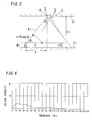
- Figs. 4 and 5 show outputs of the frequency analyzer 14, and a horizontal axis of each figure shows a frequency [Hz] and a vertical axis of each figure shows voltage intensity [mV].
- the noise determining unit 15 determines that the surrounding environment is in "stable state"
- the determining unit 12 compares a threshold value with an output of each amplifier 18 with respect to band passes of all amplifiers 18, and then the presence or absence of the detection target object M1 is determined.
- the determining unit 12 compares a threshold value with outputs of amplifiers 18 only with respect to band passes (that is, 0 to 30 [Hz] and 40 to 200 [Hz]) other than the band pass of 30 to 40 [Hz], and then the presence or absence of the detection target object M1 is determined.
- the noise rejection unit 22 invalidates an output of an amplifier 18 having a frequency band including the noise as a band pass.
- the determining unit 12 can invalidate a frequency band including the noise produced constantly by the noise source and can determine the presence or absence of the detection target object M1. Therefore, the object detection device 1 can detect the presence or absence of the detection target object M1 without receiving the influence of a noise of a particular frequency produced constantly and can improve sensitivity of detection.
- the object detection device 1 can distinguish a signal component of the sensor signal from a noise produced constantly. That is, the frequency (Doppler frequency) "f d " of the sensor signal always changes according to a moving speed "V" of the detection target object M1 and a horizontal distance "x" from the sensor 10 to the detection target object M1 as explained above.
- the outputted sensor signal is not produced constantly with a particular frequency, when the detection target object M1 is detected.
- the noise determining unit 15 does not determine that the surrounding environment is in "stable state", when the detection target object M1 is detected.
- the noise rejection unit 22 can distinguish the sensor signal, outputted upon detection of the detection target object M1, from a noise produced constantly, and can invalidate only a frequency band including the noise.
- the amplifying circuit 11 divides a frequency band of 0 to 200 [Hz] into a plurality of frequency bands so that each of the plurality of frequency bands is narrower than the bandwidth (40 to 50 [Hz]) of the sensor signal outputted upon detection of the detection target object M1. Therefore, when invalidating a frequency band including a noise of a particular frequency, the object detection device 1 can prevent all signal components from being invalidated and can prevent that sensitivity of detection is decreased, as much as possible.
- the determining unit 12 is configured to redefine the threshold value compared with the output of the amplifying circuit 11 when the noise determining unit 15 determines that the surrounding environment is in "stable state".
- the determining unit 12 stores peak to peak "Vpp" in outputs "V" of each amplifier 18 at the same timing that the noise determining unit 15 stores the intensity data every 1 [s].
- the threshold value "Vth” is always updated and then can be defined in stable state according to the surrounding environment where the object detection device 1 is located. Therefore, sensitivity of detection of the detection target object M1 can be improved.
- the detection target object M1 may be a moving object, such as a vehicle.
- the sensor 10 is not limited to the above-mentioned millimeter-wave sensor and may be a microwave sensor using a microwave or a distance measuring sensor using, for example, an ultrasonic wave as a detection wave and detecting a distance to an object in the detection area A1. Then, even when the sensor 10 is the distance measuring sensor, a frequency of a received ultrasonic wave has some level of bandwidth. Therefore, even if invalidating a frequency band including a noise of a particular frequency, the object detection device 1 can detect the detection target object M1 by using the remaining frequency band.
Landscapes
- Engineering & Computer Science (AREA)
- Radar, Positioning & Navigation (AREA)
- Remote Sensing (AREA)
- Physics & Mathematics (AREA)
- Computer Networks & Wireless Communication (AREA)
- General Physics & Mathematics (AREA)
- Electromagnetism (AREA)
- Acoustics & Sound (AREA)
- Geophysics And Detection Of Objects (AREA)
- Radar Systems Or Details Thereof (AREA)
Claims (6)
- Objekterkennungsvorrichtung (1), Folgendes umfassend:einen aktiven Sensor (10), welcher konfiguriert ist, eine Detektionswelle in einen vorgegebenen Detektionsbereich (A1) zu übertragen und die von einem Detektionszielobjekt (M1) reflektierte Detektionswelle, zu empfangen, um das Vorhandensein oder Nicht-Vorhandensein des Detektionszielobjekts (M1) im vorgegebenen Detektionsbereich (A1) zu erkennen, und ein Sensorsignal auszugeben;einen Signalprozessor, der konfiguriert ist, das vom aktiven Sensor (10) ausgegebene Sensorsignal in aufgeteilte Sensorsignale aufzuteilen und die aufgeteilten Sensorsignale auszugeben, wobei die aufgeteilten Sensorsignale mehreren Frequenzbändern entsprechen;einen Frequenzanalysator (14), der konfiguriert ist, eine Signalintensität des individuellen Frequenzen des vom aktiven Sensor 10) ausgegebenen Sensorsignals. zu detektieren, welches, die in 1 [Hz] Einheiten voneinander beabstandet sind;gekennzeichnet durcheine Bestimmungseinheit (12), die konfiguriert ist, das Vorhandensein oder das Nicht-Vorhandensein des Detektionszielobjekts (M1) durch Vergleichen nicht-ungültiger, aufgeteilter Sensorsignale, die vom Signalprozessor ausgegeben werden, jeweils mit mehreren vorbestimmten Schwellenwerten zu bestimmen, wobei die mehreren vorbestimmten Schwellenwerte jeweils hinsichtlich der mehreren Frequenzbänder definiert sind; undeine Störgeräusche-Zurückweisungseinheit (22), welche konfiguriert ist, die Bestimmungseinheit (12) zu veranlassen, unter den aufgeteilten Sensorsignalen, ein aufgeteiltes Sensorsignal eines Frequenzbands, das ein Störgeräusch eines bestimmten der individuellen Frequenzen aufweist, für ungültig zu erklären, wobei ein Störgeräusch erkannt wird, wenn die Signalintensität der bestimmten individuellen Frequenz, die vom Frequenzanalysator (14) ausgegeben wird, größer oder gleich einem definierten Wert ist, wenn das Störgeräusch kontinuierlich aus der Signalintensität der bestimmten individuellen Frequenz, die vom Frequenzanalysator (14) ausgegeben wird, erkannt wird.
- Objekterkennungsvorrichtung (1) nach Anspruch 1, wobei der Signalprozessor einen Verstärkungsschaltkreis (11) mit mehreren Verstärkern (18) umfasst, wobei der Verstärkungsschaltkreis (11) konfiguriert ist, das Sensorsignal aufzuteilen und die aufgeteilten Sensorsignale jeweils zu verstärken und die verstärkten aufgeteilten Sensorsignale an die Bestimmungseinheit (12) auszugeben.
- Objekterkennungsvorrichtung (1) nach Anspruch 1 oder 2, wobei der aktive Sensor (10) ein Dopplersensor unter Verwendung einer Funkwelle als die Detektionswelle ist, wobei der Dopplersensor konfiguriert ist, das Sensorsignal mit einer Frequenz auszugeben, die zu einer Frequenzdifferenz zwischen der Detektionswelle, die an den Detektionsbereich (A1) übertragen wird, und der Detektionswelle äquivalent ist, die von dem Detektionszielobjekt (M1) reflektiert wird, das sich in dem Detektionsbereich (A1) bewegt.
- Objekterkennungsvorrichtung (1) nach Anspruch 3, wobei das vom aktiven Sensor (10) ausgegebene Sensorsignal ein vorbestimmtes Frequenzband aufweist, das mindestens von einer Größe des Detektionszielobjekts (M1) abhängt und welches eine Breite größer oder gleich einer vorgegebenen Breite aufweist, wenn der aktive Sensor (10) das Vorhandensein des Detektionszielobjekts (M1) erkennt,
wobei eine Bandbreite jedes der mehreren Frequenzbänder für die aufgeteilten Sensorsignale, die aus dem Signalprozessor ausgegeben werden, schmaler als die Bandbreite des vorbestimmten Frequenzbands definiert ist. - Objekterkennungsvorrichtung (1) nach einem der Ansprüche 1 bis 4,
wobei die Bestimmungseinheit (12) konfiguriert ist, die mehreren vorbestimmten Schwellenwerte gemäß der Umgebungsbedingungen in einem stabilen Zustand neu zu definieren, wo eine Variationsbreite der Signalintensität des Sensorsignals, welche von dem Frequenzanalysator (14) detektiert wird, während einer vorgegebenen Zeitspanne innerhalb eines definierten Bereichs liegt. - Beleuchtungssystem, Folgendes umfassend:die Objekterkennungsvorrichtung (1) nach einem der Ansprüche 1 bis 5; undeine Beleuchtungsvorrichtung (2), welche mit der Objekterkennungsvorrichtung (1) verbunden ist,wobei die Objekterkennungsvorrichtung (1) eine Beleuchtungssteuervorrichtung (13) umfasst, wobei die Beleuchtungssteuervorrichtung (13) einen Beleuchtungszustand der Beleuchtungsvorrichtung (2) steuert, um die Beleuchtungsvorrichtung (2) zu aktivieren, wenn das Vorhandensein des Detektionszielobjekts (M1) detektiert wird.
Applications Claiming Priority (2)
| Application Number | Priority Date | Filing Date | Title |
|---|---|---|---|
| JP2009196108A JP5584442B2 (ja) | 2009-08-26 | 2009-08-26 | 物体検知装置およびそれを備えた照明システム |
| PCT/JP2010/063491 WO2011024634A1 (ja) | 2009-08-26 | 2010-08-09 | 物体検知装置およびそれを備えた照明システム |
Publications (3)
| Publication Number | Publication Date |
|---|---|
| EP2472292A1 EP2472292A1 (de) | 2012-07-04 |
| EP2472292A4 EP2472292A4 (de) | 2013-01-16 |
| EP2472292B1 true EP2472292B1 (de) | 2016-09-28 |
Family
ID=43627740
Family Applications (1)
| Application Number | Title | Priority Date | Filing Date |
|---|---|---|---|
| EP10811684.9A Not-in-force EP2472292B1 (de) | 2009-08-26 | 2010-08-09 | Objekterkennungsvorrichtung und damit ausgestattetes beleuchtungssystem |
Country Status (5)
| Country | Link |
|---|---|
| US (1) | US9146310B2 (de) |
| EP (1) | EP2472292B1 (de) |
| JP (1) | JP5584442B2 (de) |
| CN (1) | CN102597810B (de) |
| WO (1) | WO2011024634A1 (de) |
Families Citing this family (17)
| Publication number | Priority date | Publication date | Assignee | Title |
|---|---|---|---|---|
| JP5453053B2 (ja) * | 2009-10-27 | 2014-03-26 | パナソニック株式会社 | センサシステム |
| EP2571335A3 (de) * | 2011-09-15 | 2014-06-18 | Ingenium, Ingenieria Y Domotica S.L., Parque Tecnologico de | Bewegungsmelder |
| JP5895213B2 (ja) * | 2012-05-29 | 2016-03-30 | パナソニックIpマネジメント株式会社 | 照明装置 |
| JP5942166B2 (ja) * | 2012-05-29 | 2016-06-29 | パナソニックIpマネジメント株式会社 | 照明装置 |
| JP6041188B2 (ja) | 2012-06-01 | 2016-12-07 | パナソニックIpマネジメント株式会社 | センサ装置 |
| EP2857860A4 (de) * | 2012-06-05 | 2015-06-17 | Panasonic Ip Man Co Ltd | Signalverarbeitungsvorrichtung |
| JP6249325B2 (ja) | 2012-12-28 | 2017-12-20 | パナソニックIpマネジメント株式会社 | 信号処理装置 |
| RU2653357C2 (ru) | 2013-05-03 | 2018-05-08 | Филипс Лайтинг Холдинг Б.В. | Уменьшение искажения при распознавании |
| CN103543447B (zh) * | 2013-09-22 | 2016-08-10 | 浙江工商大学 | 超声波短距高精度测量中环境噪音剔除方法 |
| DE102015107221B4 (de) * | 2015-05-08 | 2018-04-12 | Sick Ag | Elektromagnetischer Näherungssensor und Verfahren zur Erfassung eines Zielobjekts |
| JP6755002B2 (ja) * | 2016-05-26 | 2020-09-16 | パナソニックIpマネジメント株式会社 | センサ装置及び照明装置 |
| CN106618588A (zh) * | 2017-02-28 | 2017-05-10 | 广东工业大学 | 一种基于脉搏反馈的自动检测人体摔倒传感方法及装置 |
| CN107703553A (zh) * | 2017-08-17 | 2018-02-16 | 广州隽智智能科技有限公司 | 一种在位行为监测方法及系统 |
| WO2020120273A1 (en) * | 2018-12-12 | 2020-06-18 | Signify Holding B.V. | A motion detector, a luminaire, a corresponding method |
| EP3928122B9 (de) * | 2019-02-22 | 2023-11-15 | Signify Holding B.V. | Leuchte mit bewegungsdetektor, und zugehöriges verfahren |
| US11709245B2 (en) * | 2019-04-29 | 2023-07-25 | Adnoviv Inc. | System and methods for radar-based detection of people in a room |
| EP3910369A1 (de) * | 2020-05-13 | 2021-11-17 | Stichting IMEC Nederland | Radardetektionssensor, -system und -verfahren |
Family Cites Families (6)
| Publication number | Priority date | Publication date | Assignee | Title |
|---|---|---|---|---|
| JP2001166052A (ja) * | 1999-12-09 | 2001-06-22 | Mazda Motor Corp | 物体位置検出装置 |
| DE602006000022T2 (de) * | 2005-01-25 | 2007-10-11 | Mazda Motor Corp. | Umgebungsüberwachungssystem |
| JP2008111773A (ja) * | 2006-10-31 | 2008-05-15 | Mitsubishi Electric Corp | 車載用レーダ装置 |
| JP5061623B2 (ja) * | 2007-01-30 | 2012-10-31 | 株式会社デンソー | レーダ装置 |
| JP5030289B2 (ja) * | 2007-11-26 | 2012-09-19 | パナソニック株式会社 | 照明器具 |
| JP5360950B2 (ja) | 2008-01-21 | 2013-12-04 | パナソニック株式会社 | 照明器具 |
-
2009
- 2009-08-26 JP JP2009196108A patent/JP5584442B2/ja active Active
-
2010
- 2010-08-09 EP EP10811684.9A patent/EP2472292B1/de not_active Not-in-force
- 2010-08-09 WO PCT/JP2010/063491 patent/WO2011024634A1/ja not_active Ceased
- 2010-08-09 US US13/392,219 patent/US9146310B2/en not_active Expired - Fee Related
- 2010-08-09 CN CN201080037565.7A patent/CN102597810B/zh not_active Expired - Fee Related
Also Published As
| Publication number | Publication date |
|---|---|
| JP5584442B2 (ja) | 2014-09-03 |
| EP2472292A4 (de) | 2013-01-16 |
| CN102597810A (zh) | 2012-07-18 |
| CN102597810B (zh) | 2015-10-14 |
| JP2011047779A (ja) | 2011-03-10 |
| WO2011024634A1 (ja) | 2011-03-03 |
| US20130009555A1 (en) | 2013-01-10 |
| EP2472292A1 (de) | 2012-07-04 |
| US9146310B2 (en) | 2015-09-29 |
Similar Documents
| Publication | Publication Date | Title |
|---|---|---|
| EP2472292B1 (de) | Objekterkennungsvorrichtung und damit ausgestattetes beleuchtungssystem | |
| ES2357723T3 (es) | Detección de una dirección de movimiento de desplazamiento con un control automático de la ganancia. | |
| US7036390B2 (en) | Method for detecting human body in a vehicle | |
| US8004451B2 (en) | Adaptive microwave security sensor | |
| AU2002258137B2 (en) | Dual sensor intruder alarm | |
| US20040129883A1 (en) | Passive infrared device for detection of boundary crossings | |
| US8058819B2 (en) | Illumination system | |
| WO2006137477A1 (ja) | 侵入検知センサ | |
| US11789136B2 (en) | Radar presence sensor device | |
| US20070115164A1 (en) | Microwave smart motion sensor for security applications | |
| AU2020417054A1 (en) | State detection | |
| AU714599B2 (en) | Countermeasure circuit for a laser speed detector | |
| EP1884901A1 (de) | System und Verfahren zur Bewegungsdetektion mit auswählbarer Reichweite | |
| CN114879184A (zh) | 雷达、扶梯的失效检测方法、装置、电子设备和存储介质 | |
| US20140118170A1 (en) | Vehicle detector | |
| US20120292492A1 (en) | Device for controlling a driven movement element, particularly a door or a gate | |
| US8013309B2 (en) | Microwave sensor capable of preventing false alarms due to a bush or tree or the like swaying in the wind | |
| US20040189510A1 (en) | Intrusion identification system using microwave barrier | |
| US20240285189A1 (en) | Fall detection | |
| KR20050064790A (ko) | 마이크로웨이브와 적외선을 이용한 복합 감지기 | |
| EP4085437B1 (de) | Zustandserkennung | |
| KR20220104913A (ko) | 초음파 센서를 이용한 어린이 감지 시스템 및 방법 | |
| CN110361793B (zh) | 探测装置及探测方法 | |
| KR20050048809A (ko) | 차폐물 검지회로가 내장된 방범용 마이크로웨이브 감지기 | |
| JP2785893B2 (ja) | 自動ドアーの起動スイッチ装置 |
Legal Events
| Date | Code | Title | Description |
|---|---|---|---|
| PUAI | Public reference made under article 153(3) epc to a published international application that has entered the european phase |
Free format text: ORIGINAL CODE: 0009012 |
|
| 17P | Request for examination filed |
Effective date: 20120208 |
|
| AK | Designated contracting states |
Kind code of ref document: A1 Designated state(s): AL AT BE BG CH CY CZ DE DK EE ES FI FR GB GR HR HU IE IS IT LI LT LU LV MC MK MT NL NO PL PT RO SE SI SK SM TR |
|
| DAX | Request for extension of the european patent (deleted) | ||
| A4 | Supplementary search report drawn up and despatched |
Effective date: 20121219 |
|
| RIC1 | Information provided on ipc code assigned before grant |
Ipc: G08B 13/183 20060101ALI20121213BHEP Ipc: G01V 3/12 20060101AFI20121213BHEP Ipc: G01S 7/292 20060101ALI20121213BHEP Ipc: G01S 7/02 20060101ALI20121213BHEP Ipc: G01S 15/52 20060101ALI20121213BHEP Ipc: G01S 7/32 20060101ALI20121213BHEP Ipc: G01S 13/56 20060101ALI20121213BHEP Ipc: G01S 17/50 20060101ALI20121213BHEP Ipc: G08B 13/16 20060101ALI20121213BHEP Ipc: H05B 37/02 20060101ALI20121213BHEP |
|
| RAP1 | Party data changed (applicant data changed or rights of an application transferred) |
Owner name: PANASONIC INTELLECTUAL PROPERTY MANAGEMENT CO., LT |
|
| GRAP | Despatch of communication of intention to grant a patent |
Free format text: ORIGINAL CODE: EPIDOSNIGR1 |
|
| INTG | Intention to grant announced |
Effective date: 20151029 |
|
| GRAP | Despatch of communication of intention to grant a patent |
Free format text: ORIGINAL CODE: EPIDOSNIGR1 |
|
| INTG | Intention to grant announced |
Effective date: 20160329 |
|
| GRAS | Grant fee paid |
Free format text: ORIGINAL CODE: EPIDOSNIGR3 |
|
| GRAA | (expected) grant |
Free format text: ORIGINAL CODE: 0009210 |
|
| AK | Designated contracting states |
Kind code of ref document: B1 Designated state(s): AL AT BE BG CH CY CZ DE DK EE ES FI FR GB GR HR HU IE IS IT LI LT LU LV MC MK MT NL NO PL PT RO SE SI SK SM TR |
|
| REG | Reference to a national code |
Ref country code: GB Ref legal event code: FG4D |
|
| REG | Reference to a national code |
Ref country code: CH Ref legal event code: EP |
|
| REG | Reference to a national code |
Ref country code: AT Ref legal event code: REF Ref document number: 833231 Country of ref document: AT Kind code of ref document: T Effective date: 20161015 |
|
| REG | Reference to a national code |
Ref country code: IE Ref legal event code: FG4D |
|
| REG | Reference to a national code |
Ref country code: DE Ref legal event code: R096 Ref document number: 602010036830 Country of ref document: DE |
|
| REG | Reference to a national code |
Ref country code: LT Ref legal event code: MG4D |
|
| PG25 | Lapsed in a contracting state [announced via postgrant information from national office to epo] |
Ref country code: NO Free format text: LAPSE BECAUSE OF FAILURE TO SUBMIT A TRANSLATION OF THE DESCRIPTION OR TO PAY THE FEE WITHIN THE PRESCRIBED TIME-LIMIT Effective date: 20161228 Ref country code: HR Free format text: LAPSE BECAUSE OF FAILURE TO SUBMIT A TRANSLATION OF THE DESCRIPTION OR TO PAY THE FEE WITHIN THE PRESCRIBED TIME-LIMIT Effective date: 20160928 Ref country code: FI Free format text: LAPSE BECAUSE OF FAILURE TO SUBMIT A TRANSLATION OF THE DESCRIPTION OR TO PAY THE FEE WITHIN THE PRESCRIBED TIME-LIMIT Effective date: 20160928 Ref country code: LT Free format text: LAPSE BECAUSE OF FAILURE TO SUBMIT A TRANSLATION OF THE DESCRIPTION OR TO PAY THE FEE WITHIN THE PRESCRIBED TIME-LIMIT Effective date: 20160928 |
|
| REG | Reference to a national code |
Ref country code: NL Ref legal event code: MP Effective date: 20160928 |
|
| REG | Reference to a national code |
Ref country code: AT Ref legal event code: MK05 Ref document number: 833231 Country of ref document: AT Kind code of ref document: T Effective date: 20160928 |
|
| PG25 | Lapsed in a contracting state [announced via postgrant information from national office to epo] |
Ref country code: LV Free format text: LAPSE BECAUSE OF FAILURE TO SUBMIT A TRANSLATION OF THE DESCRIPTION OR TO PAY THE FEE WITHIN THE PRESCRIBED TIME-LIMIT Effective date: 20160928 Ref country code: GR Free format text: LAPSE BECAUSE OF FAILURE TO SUBMIT A TRANSLATION OF THE DESCRIPTION OR TO PAY THE FEE WITHIN THE PRESCRIBED TIME-LIMIT Effective date: 20161229 Ref country code: SE Free format text: LAPSE BECAUSE OF FAILURE TO SUBMIT A TRANSLATION OF THE DESCRIPTION OR TO PAY THE FEE WITHIN THE PRESCRIBED TIME-LIMIT Effective date: 20160928 Ref country code: NL Free format text: LAPSE BECAUSE OF FAILURE TO SUBMIT A TRANSLATION OF THE DESCRIPTION OR TO PAY THE FEE WITHIN THE PRESCRIBED TIME-LIMIT Effective date: 20160928 |
|
| PG25 | Lapsed in a contracting state [announced via postgrant information from national office to epo] |
Ref country code: RO Free format text: LAPSE BECAUSE OF FAILURE TO SUBMIT A TRANSLATION OF THE DESCRIPTION OR TO PAY THE FEE WITHIN THE PRESCRIBED TIME-LIMIT Effective date: 20160928 Ref country code: EE Free format text: LAPSE BECAUSE OF FAILURE TO SUBMIT A TRANSLATION OF THE DESCRIPTION OR TO PAY THE FEE WITHIN THE PRESCRIBED TIME-LIMIT Effective date: 20160928 |
|
| PG25 | Lapsed in a contracting state [announced via postgrant information from national office to epo] |
Ref country code: ES Free format text: LAPSE BECAUSE OF FAILURE TO SUBMIT A TRANSLATION OF THE DESCRIPTION OR TO PAY THE FEE WITHIN THE PRESCRIBED TIME-LIMIT Effective date: 20160928 Ref country code: IS Free format text: LAPSE BECAUSE OF FAILURE TO SUBMIT A TRANSLATION OF THE DESCRIPTION OR TO PAY THE FEE WITHIN THE PRESCRIBED TIME-LIMIT Effective date: 20170128 Ref country code: PT Free format text: LAPSE BECAUSE OF FAILURE TO SUBMIT A TRANSLATION OF THE DESCRIPTION OR TO PAY THE FEE WITHIN THE PRESCRIBED TIME-LIMIT Effective date: 20170130 Ref country code: CZ Free format text: LAPSE BECAUSE OF FAILURE TO SUBMIT A TRANSLATION OF THE DESCRIPTION OR TO PAY THE FEE WITHIN THE PRESCRIBED TIME-LIMIT Effective date: 20160928 Ref country code: SK Free format text: LAPSE BECAUSE OF FAILURE TO SUBMIT A TRANSLATION OF THE DESCRIPTION OR TO PAY THE FEE WITHIN THE PRESCRIBED TIME-LIMIT Effective date: 20160928 Ref country code: BE Free format text: LAPSE BECAUSE OF FAILURE TO SUBMIT A TRANSLATION OF THE DESCRIPTION OR TO PAY THE FEE WITHIN THE PRESCRIBED TIME-LIMIT Effective date: 20160928 Ref country code: BG Free format text: LAPSE BECAUSE OF FAILURE TO SUBMIT A TRANSLATION OF THE DESCRIPTION OR TO PAY THE FEE WITHIN THE PRESCRIBED TIME-LIMIT Effective date: 20161228 Ref country code: AT Free format text: LAPSE BECAUSE OF FAILURE TO SUBMIT A TRANSLATION OF THE DESCRIPTION OR TO PAY THE FEE WITHIN THE PRESCRIBED TIME-LIMIT Effective date: 20160928 Ref country code: SM Free format text: LAPSE BECAUSE OF FAILURE TO SUBMIT A TRANSLATION OF THE DESCRIPTION OR TO PAY THE FEE WITHIN THE PRESCRIBED TIME-LIMIT Effective date: 20160928 Ref country code: PL Free format text: LAPSE BECAUSE OF FAILURE TO SUBMIT A TRANSLATION OF THE DESCRIPTION OR TO PAY THE FEE WITHIN THE PRESCRIBED TIME-LIMIT Effective date: 20160928 |
|
| REG | Reference to a national code |
Ref country code: DE Ref legal event code: R097 Ref document number: 602010036830 Country of ref document: DE |
|
| PG25 | Lapsed in a contracting state [announced via postgrant information from national office to epo] |
Ref country code: IT Free format text: LAPSE BECAUSE OF FAILURE TO SUBMIT A TRANSLATION OF THE DESCRIPTION OR TO PAY THE FEE WITHIN THE PRESCRIBED TIME-LIMIT Effective date: 20160928 |
|
| PG25 | Lapsed in a contracting state [announced via postgrant information from national office to epo] |
Ref country code: DK Free format text: LAPSE BECAUSE OF FAILURE TO SUBMIT A TRANSLATION OF THE DESCRIPTION OR TO PAY THE FEE WITHIN THE PRESCRIBED TIME-LIMIT Effective date: 20160928 |
|
| PLBE | No opposition filed within time limit |
Free format text: ORIGINAL CODE: 0009261 |
|
| STAA | Information on the status of an ep patent application or granted ep patent |
Free format text: STATUS: NO OPPOSITION FILED WITHIN TIME LIMIT |
|
| 26N | No opposition filed |
Effective date: 20170629 |
|
| PG25 | Lapsed in a contracting state [announced via postgrant information from national office to epo] |
Ref country code: SI Free format text: LAPSE BECAUSE OF FAILURE TO SUBMIT A TRANSLATION OF THE DESCRIPTION OR TO PAY THE FEE WITHIN THE PRESCRIBED TIME-LIMIT Effective date: 20160928 |
|
| REG | Reference to a national code |
Ref country code: CH Ref legal event code: PL |
|
| PG25 | Lapsed in a contracting state [announced via postgrant information from national office to epo] |
Ref country code: MC Free format text: LAPSE BECAUSE OF FAILURE TO SUBMIT A TRANSLATION OF THE DESCRIPTION OR TO PAY THE FEE WITHIN THE PRESCRIBED TIME-LIMIT Effective date: 20160928 |
|
| GBPC | Gb: european patent ceased through non-payment of renewal fee |
Effective date: 20170809 |
|
| PG25 | Lapsed in a contracting state [announced via postgrant information from national office to epo] |
Ref country code: LI Free format text: LAPSE BECAUSE OF NON-PAYMENT OF DUE FEES Effective date: 20170831 Ref country code: CH Free format text: LAPSE BECAUSE OF NON-PAYMENT OF DUE FEES Effective date: 20170831 |
|
| REG | Reference to a national code |
Ref country code: FR Ref legal event code: ST Effective date: 20180430 |
|
| REG | Reference to a national code |
Ref country code: IE Ref legal event code: MM4A |
|
| PG25 | Lapsed in a contracting state [announced via postgrant information from national office to epo] |
Ref country code: LU Free format text: LAPSE BECAUSE OF NON-PAYMENT OF DUE FEES Effective date: 20170809 |
|
| PG25 | Lapsed in a contracting state [announced via postgrant information from national office to epo] |
Ref country code: GB Free format text: LAPSE BECAUSE OF NON-PAYMENT OF DUE FEES Effective date: 20170809 Ref country code: IE Free format text: LAPSE BECAUSE OF NON-PAYMENT OF DUE FEES Effective date: 20170809 |
|
| PG25 | Lapsed in a contracting state [announced via postgrant information from national office to epo] |
Ref country code: FR Free format text: LAPSE BECAUSE OF NON-PAYMENT OF DUE FEES Effective date: 20170831 |
|
| PG25 | Lapsed in a contracting state [announced via postgrant information from national office to epo] |
Ref country code: MT Free format text: LAPSE BECAUSE OF NON-PAYMENT OF DUE FEES Effective date: 20170809 |
|
| PG25 | Lapsed in a contracting state [announced via postgrant information from national office to epo] |
Ref country code: AL Free format text: LAPSE BECAUSE OF FAILURE TO SUBMIT A TRANSLATION OF THE DESCRIPTION OR TO PAY THE FEE WITHIN THE PRESCRIBED TIME-LIMIT Effective date: 20160928 |
|
| PG25 | Lapsed in a contracting state [announced via postgrant information from national office to epo] |
Ref country code: HU Free format text: LAPSE BECAUSE OF FAILURE TO SUBMIT A TRANSLATION OF THE DESCRIPTION OR TO PAY THE FEE WITHIN THE PRESCRIBED TIME-LIMIT; INVALID AB INITIO Effective date: 20100809 |
|
| PG25 | Lapsed in a contracting state [announced via postgrant information from national office to epo] |
Ref country code: CY Free format text: LAPSE BECAUSE OF NON-PAYMENT OF DUE FEES Effective date: 20160928 |
|
| PGFP | Annual fee paid to national office [announced via postgrant information from national office to epo] |
Ref country code: DE Payment date: 20190822 Year of fee payment: 10 |
|
| PG25 | Lapsed in a contracting state [announced via postgrant information from national office to epo] |
Ref country code: MK Free format text: LAPSE BECAUSE OF FAILURE TO SUBMIT A TRANSLATION OF THE DESCRIPTION OR TO PAY THE FEE WITHIN THE PRESCRIBED TIME-LIMIT Effective date: 20160928 |
|
| PG25 | Lapsed in a contracting state [announced via postgrant information from national office to epo] |
Ref country code: TR Free format text: LAPSE BECAUSE OF FAILURE TO SUBMIT A TRANSLATION OF THE DESCRIPTION OR TO PAY THE FEE WITHIN THE PRESCRIBED TIME-LIMIT Effective date: 20160928 |
|
| REG | Reference to a national code |
Ref country code: DE Ref legal event code: R119 Ref document number: 602010036830 Country of ref document: DE |
|
| PG25 | Lapsed in a contracting state [announced via postgrant information from national office to epo] |
Ref country code: DE Free format text: LAPSE BECAUSE OF NON-PAYMENT OF DUE FEES Effective date: 20210302 |