EP2472012A2 - Dispositif d'arrivée d'air sur un réseau de conduites d'eau s'étendant sous terre dans le sol - Google Patents
Dispositif d'arrivée d'air sur un réseau de conduites d'eau s'étendant sous terre dans le sol Download PDFInfo
- Publication number
- EP2472012A2 EP2472012A2 EP12405001A EP12405001A EP2472012A2 EP 2472012 A2 EP2472012 A2 EP 2472012A2 EP 12405001 A EP12405001 A EP 12405001A EP 12405001 A EP12405001 A EP 12405001A EP 2472012 A2 EP2472012 A2 EP 2472012A2
- Authority
- EP
- European Patent Office
- Prior art keywords
- flow passage
- float
- air
- chamber
- hydrant
- Prior art date
- Legal status (The legal status is an assumption and is not a legal conclusion. Google has not performed a legal analysis and makes no representation as to the accuracy of the status listed.)
- Granted
Links
Images


Classifications
-
- E—FIXED CONSTRUCTIONS
- E03—WATER SUPPLY; SEWERAGE
- E03B—INSTALLATIONS OR METHODS FOR OBTAINING, COLLECTING, OR DISTRIBUTING WATER
- E03B9/00—Methods or installations for drawing-off water
- E03B9/02—Hydrants; Arrangements of valves therein; Keys for hydrants
-
- E—FIXED CONSTRUCTIONS
- E03—WATER SUPPLY; SEWERAGE
- E03B—INSTALLATIONS OR METHODS FOR OBTAINING, COLLECTING, OR DISTRIBUTING WATER
- E03B1/00—Methods or layout of installations for water supply
- E03B1/02—Methods or layout of installations for water supply for public or like main supply for industrial use
-
- E—FIXED CONSTRUCTIONS
- E03—WATER SUPPLY; SEWERAGE
- E03B—INSTALLATIONS OR METHODS FOR OBTAINING, COLLECTING, OR DISTRIBUTING WATER
- E03B7/00—Water main or service pipe systems
- E03B7/02—Public or like main pipe systems
-
- E—FIXED CONSTRUCTIONS
- E03—WATER SUPPLY; SEWERAGE
- E03B—INSTALLATIONS OR METHODS FOR OBTAINING, COLLECTING, OR DISTRIBUTING WATER
- E03B9/00—Methods or installations for drawing-off water
- E03B9/02—Hydrants; Arrangements of valves therein; Keys for hydrants
- E03B9/04—Column hydrants
-
- E—FIXED CONSTRUCTIONS
- E03—WATER SUPPLY; SEWERAGE
- E03B—INSTALLATIONS OR METHODS FOR OBTAINING, COLLECTING, OR DISTRIBUTING WATER
- E03B9/00—Methods or installations for drawing-off water
- E03B9/02—Hydrants; Arrangements of valves therein; Keys for hydrants
- E03B9/08—Underground hydrants
Definitions
- the invention relates to a device for guiding air on an underground water network extending in the area. Ventilation of the pipeline network is required during initial or renewed commissioning and during operation to protect downstream valves and connected devices against defects and to guarantee their operational safety. Aeration of the water supply network is appropriate for preventing massive damage, namely in the event of a disaster - in the event of a major leak or breakage in the pipeline network - or if the pipeline network is intentionally emptied, as a result of which a negative pressure with the risk of line implosion would arise with respect to the atmosphere.
- venting of the underground, underground water supply network is usually carried out at first or re-commissioning by opening the nearby hydrant hydrant.
- ventilation devices eg from Hawle Armaturen GmbH, D-83395 Freilassing / Germany, are known (see their homepage under www.hawle.de/ products / valves and valves for cleaning valves. These equipment already cause considerable purchase and installation costs. Accommodation is usually in underground shafts. In addition to the additional maintenance, the devices are also not optimal from a hygienic standpoint, since when airing the power network hardly clean air is sucked.
- Above-ground manholes eliminate the hygiene problem, however, such manholes for accessibility to the maintenance of the equipment are voluminous to dimension and represent an obstacle in the spatial planning. Therefore, installations with shafts extending to above-ground only in small numbers, usually near reservoirs or other high points.
- the invention has for its object to provide a technically and hygienically improved and more cost-effective device for guiding air on an underground already existing or newly designed water supply network.
- the air control system comprises at least venting the water supply network.
- a further configured device should also allow air guidance in the opposite direction of flow, namely for ventilation of the water supply network.
- the device designed for guiding the air of an underground water supply network has a hydrant-integrated air duct assembly, which is intended for the automatic discharge of air into the atmosphere through the hydrant of the dammed air supplied to it from the water supply network.
- the air guide assembly is on the one hand rigidly connected to the closing body and the other rigidly connected to a particular valve body for actuating the closing body.
- the float is provided with a seal for closing the inner mouth of the third flow passage.
- the secondary part fits sealed into the second flow passage of the primary part.
- the chamber has a cylindrical chamber jacket with an inner surface. Between the inner surface of the chamber shell and the float guided in the chamber remains a flow gap.
- the float has external elements which serve to guide the float in the chamber while maintaining the flow gap.
- the secondary part of the air valve has first support elements which serve to guide the chamber and to position it on the float, and second abutment elements are provided on the secondary part for positioning in the second flow passage.
- the air guide assembly has a floating buoyant body designed to ascend water accumulating in the lower riser and to block entry into the breakthrough to prevent such water from entering the conduit network.
- the hydrant is installed in the aqueduct, with respect to the normal zero, preferably at an elevated level, which fills and collects air from the water mains.
- the device with the air guide assembly can be retrofitted to an existing hydrant.
- the integrated hydrant air duct assembly is, in addition to the automatic air flow into the atmosphere through the hydrant of this from the water supply network accumulated air, also intended for automatic air flow from the atmosphere through the hydrant into the water network at low pressure occurring in the water network.
- the first support elements have centrally projecting towards the float projecting lugs, which engage in a diameter constriction on the float.
- the diameter constriction ends at the top of a radially projecting annular shoulder, which acts as a suspension with sunken float.
- the secondary part has an annular gap lying above the annular shoulder and distributed over the circumference in sections, which serves as a filter in order to retain impurities.
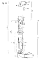
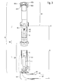
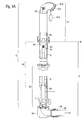
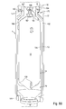
- the hydrant 9 - in the example shown, a conventional Matterflurhydrant - has the top of the top tube 91 , which extends above the earth level E in height.
- the attachment tube 91 has the usual components, such as cap and hose connection 910, at which the opening 911 opens to the water outlet. When not in use, the hose fitting 910 and opening 911 are usually protected with an attachable cover 912 .
- a spindle extension 84 is further accessible for actuating the end body 7 with its valve function.
- the upper riser 92 joins, in which the known components, such as spindle bearings 83 , spindle 82 and spindle nut 81 are arranged.
- the valve rod 8 extends downward.
- the upper riser 92 inserted telescopically height adjustable in the lower riser 93 to adjust the hydrant 9 to the given at the respective location grave depth G , which is the distance between the earth level E and the lower edge of the means connected by the screw ring 95 on the inlet bend 94 supply line 96 is defined.
- the principle of such a height-adjustable hydrant is the subject of EP 0 717 156 B1 ,
- the supply line 96 leads to the water network 97 .
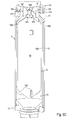
- the air guide assembly 1 first variant is arranged, which initially consists essentially of a cylindrical chamber 10 surrounded by a jacket 13 , at its lower first end 101, a tubular connecting piece 11 to the closing body. 7 leads.
- an air valve 16 sets, which in turn is connected to the lower end of the valve rod 8 .
- the air valve 16 has a primary part 160 , which represents the connection between the valve rod 8 and the second chamber end 102 .
- the primary part 160 has in the interior of the risers 92 , 93 opening openings 161st
- the valve function of the end body 7 is created by the interaction of valve seal 71 mounted on the end body 7 and the valve seat 70 present on the lower riser 93 .
- a coarse filter 75 is arranged to protect the air guide assembly 1 from mechanical damage.
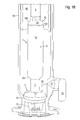
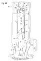
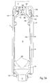
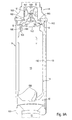
- FIGS. 1C to 1F normal state
- the float 15 is provided with the seal 151 for closing the inner mouth of the third flow passage 168 .
- the secondary part 165 sits sealed in the second flow passage 162 of the primary part 160.
- the chamber 10 has the cylindrical chamber jacket 13 with the inner surface 130th Between the inner surface 130 of the chamber jacket 13 and the float 15 guided in the chamber 10 , the flow gap 14 remains.
- the float 15 has outer elements 150 , which serve to guide the float 15 in the chamber 10 while maintaining the flow gap 14 .
- the secondary part 165 of the air valve 16 has first support elements 166, which serve to guide the chamber 10 and the positioning on the float 15 .
- second support elements 167 are provided for positioning in the second flow passage 162 .
- the air guide assembly 1 is on the one hand rigidly connected to the closing body 7 and on the other hand rigidly connected to the valve body 8 intended for actuating the closing body 7 .
- the opening 911 on the hose connection 910 on the attachment tube 91 is preferably provided with a sieve and / or filter.
- Such Spray water would flow through the riser 93 of the drainage opening 77 , which otherwise serves to empty the hydrant 9 after use with the closing body 7 closed again.
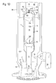
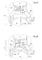
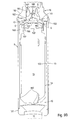
- FIGS. 4A to 4D (automatic operating ventilation)
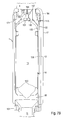
- the flow gap 14 between the shell inner surface 130 and the float 15 is so far filled with a passing through the first flow passage 76 of the end body 7 air volume 12 from the conduit network 97 that the float 15 undergoes reduced buoyancy, with its seal 151, the inner mouth of the third Flow passage 168 at the secondary part 165 of the air valve 16 releases, while the secondary part 165 by the prevailing pressure conditions in the primary part 160 , the second flow passage 162 is closed, inserted and the air volume 12 escapes through the third flow passage 168 . From here, the air volume 12 passes through the opening 161 in the primary part 160 in the upper riser 92 to the opening 911 on the hydrant 9 to flow into the atmosphere. Eventually by the third Flow passage 168 spraying spray water flows through the lower riser 93 to the drainage opening 77 and exits into the soil.
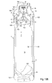
- a negative pressure which continues from the line network 97 through the first flow passage 76 of the end body 7 , is established in relation to the atmosphere.
- the float 15 sinks in the chamber 10
- the secondary part 165 moves through the prevailing pressure conditions from the primary part 160 and thus releases the second flow passage 162 free.
- air from the atmosphere via the opening 911 at the hose connection 910 through the top tube 91 and the upper riser 92 , the opening 161 and the second flow passage 162 in the primary part 160 , the flow gap 14 in the chamber 10 and the first flow passage 76 in the closing body. 7 to get into the network of lines 97 to compensate for the resulting from the accident vacuum.
- the device In this state, with the float 15 lowered to the first end of the chamber 101 and the secondary part 165 pushed out of the primary part 160 , the device is also in the delivery state or before being put into operation.
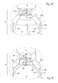
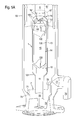
- FIGS. 6A to 8B normal state
- the air guide assembly 1 is shown unsealed and sealed in the second to fourth variant , starting from the ongoing operation of the line network 97 (s. Figures 1C-1F ).
- the closing body 7 is in the closed valve position and the air guide assembly 1 in the normal state, ie there is no automatic operating ventilation of the line network 97 (s. Figures 4A-4D ).
- the in case of emergency automatically operated ventilation of the network 97 (s. Figures 5A-5D ) is only possible in the unsealed situation described later.
- the air guide assembly 1 in the second to fourth variant causes, for example, as a result of flooding in the hydrant 9 pending contaminated water, which could reach via the drainage hole 77 in the lower riser 93 in the hydrant 9 , can not flow into the network 97 .
- FIG. 6B (unsealed)
- the buoyancy body 17 is of annular shape, which preferably consists of plastic, with its outer periphery quasi flush with the shell 13 and in the absence of buoyancy on the inclined surface of the primary part 160 - adjacent the upper chamber end 102nd - sits up.
- the shoulder portion 170 At the top of the buoyant body 17 has the shoulder portion 170 , on which the ring seal 171 sits.
- FIG. 6C (sealed)
- the buoyant body 17 is formed as the shell 13 outside umhüllender and axially upwardly moving in buoyancy hollow cylinder.
- the buoyant body 17 has at the top the shoulder portion 170 , in which the ring seal 171 sits.
- an open gap between the ring seal 171 and the free end of the collar 164 (s. FIG. 7A ).
- the gap between the ring seal 171 and the free end of the collar 164 is closed when the buoyant body 17 is raised (see FIG. FIG. 7B ), so that no contaminated water from the hydrant 9 can get into the network 97 .
- the buoyant body 17 is made according to the annular segment Figures 6A-6C and the hollow cylinder according to FIGS. 7A + 7B together.
- the ring seal 171 sits on top of the shoulder portion 170 of the annular segment.
- an open gap between the annular seal 171 and the free end of the collar 164 remains, in the case of a buoyant body 17 lowered by gravity (see FIG. Figure 8A ).
- Due to the thus enlarged volume of this buoyant body 17 the seal between the ring seal 171 and the free end of the collar 164 intensifies when buoyant body 17 is lifted by increased buoyancy.
- the gap between ring seal 171 and collar 164 has closed; it can not get contaminated water from the hydrant 9 in the pipe network 97 (s. FIG. 8B ).
- the secondary part 165 of the air valve 16 with the first support elements 166 is accommodated on the float 15 in an axially limited manner. Projecting lugs 169 of the first support elements 166 engage in a diameter constriction 153 on the float 15 , which ends at the top of a radially projecting annular shoulder 152 .
- the secondary part 165 has below the seal 163 lying above the annular shoulder 152 , distributed over the circumference in sections annular gap S.
- the annular gap S serves as a filter to retain contaminants that rinsed in the water through the first flow passage 76 of the end body 7 in the flow gap 14 become.
- the automatic ventilation (s. FIG. 9C ) is activated when a negative pressure arises in the line network 97 .
- the float 15 decreases, and at the same time moves the secondary part 165 from the primary part 160 downwards until the lugs 169 come to lie virtually at the bottom stop within the diameter constriction 153 .
- the second flow passage 162 is open so that atmospheric air can be sucked into the conduit network 97 via the openings 161 .
- the air guide assembly 1 of the sixth variant can be operated only in the normal state and with automatic ventilation.
- the second flow passage 162 is omitted here.
- the secondary part 165 is immovably fixedly connected to the primary part 160 .
- a disc-shaped abutment 190 is arranged, on whose underside a spring 19 is supported.
- This spring 19 acts on a spherical shut-off element 18 , which closes the third flow passage 168 , so that a check valve is formed.
- the upwardly directed second support element 167 forms a vertical guide for the shut-off element 18 .
- the float 15 is lowered in the chamber 10 , the secondary 165 sits on the float 15 , and the second flow passage 162 is open.
- the air driven from the conduit network 97 through the first flow passage 76 of the end body 7 into the chamber 10 can flow out through the second flow passage 162 , the aperture 161 , the upper riser 92 and the attachment tube 91 via the opening 911 into the atmosphere.
- the removal of spray water injected via the first flow passage 76 and the connecting piece 11 into the chamber 15 via the second flow passage 162 , the opening 161 and down in the lower riser 93 to the drainage opening 77 is relevant.
- the process is slightly different. Initially, the float 15 is again lowered by gravity into the chamber 10 and is thus spaced from the stationary secondary 165. The float seal 151 releases entry into the third flow passage 168 , however, the shut-off element 18 initially closes the outlet of the flow passage 168 .
- the increasing pressure of the discharged from the mains network 97 air volume causes a lifting of the shut-off element 18 of Outlet of the flow passage 168 against the spring 19 , so that the air volume 12 via the outlet A in the second support member 167 and the openings 161 in the primary part 160 can flow into the atmosphere.
Landscapes
- Health & Medical Sciences (AREA)
- Life Sciences & Earth Sciences (AREA)
- Engineering & Computer Science (AREA)
- Hydrology & Water Resources (AREA)
- Public Health (AREA)
- Water Supply & Treatment (AREA)
- Self-Closing Valves And Venting Or Aerating Valves (AREA)
Applications Claiming Priority (1)
| Application Number | Priority Date | Filing Date | Title |
|---|---|---|---|
| CH00014/11A CH704308A2 (de) | 2011-01-04 | 2011-01-04 | Vorrichtung zur Be- und/oder Entlüftung eines sich im Gelände unterirdisch erstreckenden Wasserleitungsnetzes. |
Publications (3)
| Publication Number | Publication Date |
|---|---|
| EP2472012A2 true EP2472012A2 (fr) | 2012-07-04 |
| EP2472012A3 EP2472012A3 (fr) | 2015-07-08 |
| EP2472012B1 EP2472012B1 (fr) | 2016-07-13 |
Family
ID=45495878
Family Applications (1)
| Application Number | Title | Priority Date | Filing Date |
|---|---|---|---|
| EP12405001.4A Active EP2472012B1 (fr) | 2011-01-04 | 2012-01-04 | Dispositif d'arrivée d'air sur un réseau de conduites d'eau s'étendant sous terre dans le sol et utilisation du dispositif |
Country Status (2)
| Country | Link |
|---|---|
| EP (1) | EP2472012B1 (fr) |
| CH (1) | CH704308A2 (fr) |
Citations (1)
| Publication number | Priority date | Publication date | Assignee | Title |
|---|---|---|---|---|
| EP0717156B1 (fr) | 1994-12-14 | 2002-08-21 | Hinni AG | Prise d'eau ajustable en hauteur |
Family Cites Families (3)
| Publication number | Priority date | Publication date | Assignee | Title |
|---|---|---|---|---|
| US820940A (en) * | 1903-08-06 | 1906-05-15 | Eugene H Sloman | Hydrant. |
| GB2129064A (en) * | 1982-10-15 | 1984-05-10 | Iuan Yang | Hydrants |
| DE10127063C1 (de) * | 2001-06-02 | 2003-01-16 | Fritz Hempelmann | Hydrant mit automatischer Lüftung |
-
2011
- 2011-01-04 CH CH00014/11A patent/CH704308A2/de not_active Application Discontinuation
-
2012
- 2012-01-04 EP EP12405001.4A patent/EP2472012B1/fr active Active
Patent Citations (1)
| Publication number | Priority date | Publication date | Assignee | Title |
|---|---|---|---|---|
| EP0717156B1 (fr) | 1994-12-14 | 2002-08-21 | Hinni AG | Prise d'eau ajustable en hauteur |
Non-Patent Citations (1)
| Title |
|---|
| "D-83395 Freilassing / Deutschland", HAWLE ARMATUREN GMBH |
Also Published As
| Publication number | Publication date |
|---|---|
| EP2472012B1 (fr) | 2016-07-13 |
| CH704308A2 (de) | 2012-07-13 |
| EP2472012A3 (fr) | 2015-07-08 |
Similar Documents
| Publication | Publication Date | Title |
|---|---|---|
| DE2757484A1 (de) | Einrichtung zur reinigung, aufweitung, reparatur und ausflussmessung in brunnen fuer trinkwasser und wasser fuer bewaesserungszwecke | |
| EP2447131B1 (fr) | Ensemble vanne pour l'évacuation d'un liquide et procédé de commande d'un ensemble vanne | |
| EP0424622B1 (fr) | Réservoir de chasse d'eau | |
| EP2275610B1 (fr) | Réservoir d'eau pour une toilette et toilette correspondante | |
| DE69104275T2 (de) | Hydrant mit Rückschlagventil. | |
| EP2472012B1 (fr) | Dispositif d'arrivée d'air sur un réseau de conduites d'eau s'étendant sous terre dans le sol et utilisation du dispositif | |
| DE10201347C5 (de) | Einlaufvorrichtung für die Abführung von Regenwasser von einem Dach | |
| DE3435778A1 (de) | Hydrant, insbesondere unterflurhydrant | |
| DE202015107000U1 (de) | Ablaufsystem | |
| EP3020878B1 (fr) | Prise d'eau et tuyau de contrôle | |
| EP3399112B1 (fr) | Bouche à eau pourvue de clapet antiretour dans la partie supérieure | |
| EP3074576A1 (fr) | Dispositif d'écoulement ainsi qu'élément tubulaire intérieur destiné à être au moins en partie inséré dans une tubulure d'entrée | |
| DE202008011255U1 (de) | Systemtrenner II | |
| EP2679869B1 (fr) | Soupape principale pour une prise d'eau | |
| DE102005041437B4 (de) | Betankungswächter | |
| EP2154300B1 (fr) | Station d'eaux usées | |
| DE10027640C1 (de) | Vorrichtung zum Be-und/oder Entlüften von Flüssigkeitsdruckleitungen sowie Verfahren zum Montieren eines Leitungsabschnittes | |
| DE19604163B4 (de) | Schutzbehälter mit Hausanschluß-Absperrventil an einer Unterdruck-Abwasserleitung | |
| EP1614816B1 (fr) | Dispositif de vidange et de trop-plein pour appareils sanitaires | |
| DE202015100399U1 (de) | Schwimmstoffabzug | |
| WO2022144287A1 (fr) | Système de bouche de prise d'incendie, et prise d'incendie comportant un tel système | |
| DE19932859C2 (de) | Aseptisches Pumpengehäuse mit schaltbarer Drainage | |
| DE102012207200A1 (de) | Hydrant mit Steinfang | |
| EP1632618A1 (fr) | Obturateur pour regard d'évacuation, en particulier pour égout | |
| DE60020356T2 (de) | Schwimmerventil mit zwei Trichtern |
Legal Events
| Date | Code | Title | Description |
|---|---|---|---|
| AK | Designated contracting states |
Kind code of ref document: A2 Designated state(s): AL AT BE BG CH CY CZ DE DK EE ES FI FR GB GR HR HU IE IS IT LI LT LU LV MC MK MT NL NO PL PT RO RS SE SI SK SM TR |
|
| AX | Request for extension of the european patent |
Extension state: BA ME |
|
| PUAI | Public reference made under article 153(3) epc to a published international application that has entered the european phase |
Free format text: ORIGINAL CODE: 0009012 |
|
| PUAL | Search report despatched |
Free format text: ORIGINAL CODE: 0009013 |
|
| AK | Designated contracting states |
Kind code of ref document: A3 Designated state(s): AL AT BE BG CH CY CZ DE DK EE ES FI FR GB GR HR HU IE IS IT LI LT LU LV MC MK MT NL NO PL PT RO RS SE SI SK SM TR |
|
| AX | Request for extension of the european patent |
Extension state: BA ME |
|
| RIC1 | Information provided on ipc code assigned before grant |
Ipc: E03B 9/08 20060101ALI20150529BHEP Ipc: E03B 1/02 20060101ALI20150529BHEP Ipc: E03B 9/04 20060101ALI20150529BHEP Ipc: E03B 9/02 20060101AFI20150529BHEP Ipc: E03B 7/02 20060101ALI20150529BHEP |
|
| 17P | Request for examination filed |
Effective date: 20151110 |
|
| RBV | Designated contracting states (corrected) |
Designated state(s): AL AT BE BG CH CY CZ DE DK EE ES FI FR GB GR HR HU IE IS IT LI LT LU LV MC MK MT NL NO PL PT RO RS SE SI SK SM TR |
|
| GRAP | Despatch of communication of intention to grant a patent |
Free format text: ORIGINAL CODE: EPIDOSNIGR1 |
|
| RIC1 | Information provided on ipc code assigned before grant |
Ipc: E03B 9/08 20060101ALI20160211BHEP Ipc: E03B 9/04 20060101ALI20160211BHEP Ipc: E03B 7/02 20060101ALI20160211BHEP Ipc: E03B 1/02 20060101ALI20160211BHEP Ipc: E03B 9/02 20060101AFI20160211BHEP |
|
| INTG | Intention to grant announced |
Effective date: 20160309 |
|
| INTG | Intention to grant announced |
Effective date: 20160314 |
|
| GRAS | Grant fee paid |
Free format text: ORIGINAL CODE: EPIDOSNIGR3 |
|
| GRAA | (expected) grant |
Free format text: ORIGINAL CODE: 0009210 |
|
| AK | Designated contracting states |
Kind code of ref document: B1 Designated state(s): AL AT BE BG CH CY CZ DE DK EE ES FI FR GB GR HR HU IE IS IT LI LT LU LV MC MK MT NL NO PL PT RO RS SE SI SK SM TR |
|
| REG | Reference to a national code |
Ref country code: GB Ref legal event code: FG4D Free format text: NOT ENGLISH |
|
| REG | Reference to a national code |
Ref country code: AT Ref legal event code: REF Ref document number: 812458 Country of ref document: AT Kind code of ref document: T Effective date: 20160715 Ref country code: CH Ref legal event code: EP |
|
| REG | Reference to a national code |
Ref country code: IE Ref legal event code: FG4D Free format text: LANGUAGE OF EP DOCUMENT: GERMAN |
|
| REG | Reference to a national code |
Ref country code: DE Ref legal event code: R096 Ref document number: 502012007626 Country of ref document: DE |
|
| REG | Reference to a national code |
Ref country code: CH Ref legal event code: NV Representative=s name: AXON PATENT GMBH, CH |
|
| REG | Reference to a national code |
Ref country code: LT Ref legal event code: MG4D |
|
| REG | Reference to a national code |
Ref country code: NL Ref legal event code: MP Effective date: 20160713 |
|
| REG | Reference to a national code |
Ref country code: FR Ref legal event code: PLFP Year of fee payment: 6 |
|
| PG25 | Lapsed in a contracting state [announced via postgrant information from national office to epo] |
Ref country code: RS Free format text: LAPSE BECAUSE OF FAILURE TO SUBMIT A TRANSLATION OF THE DESCRIPTION OR TO PAY THE FEE WITHIN THE PRESCRIBED TIME-LIMIT Effective date: 20160713 Ref country code: NO Free format text: LAPSE BECAUSE OF FAILURE TO SUBMIT A TRANSLATION OF THE DESCRIPTION OR TO PAY THE FEE WITHIN THE PRESCRIBED TIME-LIMIT Effective date: 20161013 Ref country code: FI Free format text: LAPSE BECAUSE OF FAILURE TO SUBMIT A TRANSLATION OF THE DESCRIPTION OR TO PAY THE FEE WITHIN THE PRESCRIBED TIME-LIMIT Effective date: 20160713 Ref country code: LT Free format text: LAPSE BECAUSE OF FAILURE TO SUBMIT A TRANSLATION OF THE DESCRIPTION OR TO PAY THE FEE WITHIN THE PRESCRIBED TIME-LIMIT Effective date: 20160713 Ref country code: IS Free format text: LAPSE BECAUSE OF FAILURE TO SUBMIT A TRANSLATION OF THE DESCRIPTION OR TO PAY THE FEE WITHIN THE PRESCRIBED TIME-LIMIT Effective date: 20161113 Ref country code: IT Free format text: LAPSE BECAUSE OF FAILURE TO SUBMIT A TRANSLATION OF THE DESCRIPTION OR TO PAY THE FEE WITHIN THE PRESCRIBED TIME-LIMIT Effective date: 20160713 Ref country code: NL Free format text: LAPSE BECAUSE OF FAILURE TO SUBMIT A TRANSLATION OF THE DESCRIPTION OR TO PAY THE FEE WITHIN THE PRESCRIBED TIME-LIMIT Effective date: 20160713 Ref country code: HR Free format text: LAPSE BECAUSE OF FAILURE TO SUBMIT A TRANSLATION OF THE DESCRIPTION OR TO PAY THE FEE WITHIN THE PRESCRIBED TIME-LIMIT Effective date: 20160713 |
|
| PG25 | Lapsed in a contracting state [announced via postgrant information from national office to epo] |
Ref country code: GR Free format text: LAPSE BECAUSE OF FAILURE TO SUBMIT A TRANSLATION OF THE DESCRIPTION OR TO PAY THE FEE WITHIN THE PRESCRIBED TIME-LIMIT Effective date: 20161014 Ref country code: PL Free format text: LAPSE BECAUSE OF FAILURE TO SUBMIT A TRANSLATION OF THE DESCRIPTION OR TO PAY THE FEE WITHIN THE PRESCRIBED TIME-LIMIT Effective date: 20160713 Ref country code: LV Free format text: LAPSE BECAUSE OF FAILURE TO SUBMIT A TRANSLATION OF THE DESCRIPTION OR TO PAY THE FEE WITHIN THE PRESCRIBED TIME-LIMIT Effective date: 20160713 Ref country code: ES Free format text: LAPSE BECAUSE OF FAILURE TO SUBMIT A TRANSLATION OF THE DESCRIPTION OR TO PAY THE FEE WITHIN THE PRESCRIBED TIME-LIMIT Effective date: 20160713 Ref country code: PT Free format text: LAPSE BECAUSE OF FAILURE TO SUBMIT A TRANSLATION OF THE DESCRIPTION OR TO PAY THE FEE WITHIN THE PRESCRIBED TIME-LIMIT Effective date: 20161114 Ref country code: SE Free format text: LAPSE BECAUSE OF FAILURE TO SUBMIT A TRANSLATION OF THE DESCRIPTION OR TO PAY THE FEE WITHIN THE PRESCRIBED TIME-LIMIT Effective date: 20160713 |
|
| REG | Reference to a national code |
Ref country code: DE Ref legal event code: R097 Ref document number: 502012007626 Country of ref document: DE |
|
| PG25 | Lapsed in a contracting state [announced via postgrant information from national office to epo] |
Ref country code: RO Free format text: LAPSE BECAUSE OF FAILURE TO SUBMIT A TRANSLATION OF THE DESCRIPTION OR TO PAY THE FEE WITHIN THE PRESCRIBED TIME-LIMIT Effective date: 20160713 Ref country code: EE Free format text: LAPSE BECAUSE OF FAILURE TO SUBMIT A TRANSLATION OF THE DESCRIPTION OR TO PAY THE FEE WITHIN THE PRESCRIBED TIME-LIMIT Effective date: 20160713 |
|
| PLBE | No opposition filed within time limit |
Free format text: ORIGINAL CODE: 0009261 |
|
| STAA | Information on the status of an ep patent application or granted ep patent |
Free format text: STATUS: NO OPPOSITION FILED WITHIN TIME LIMIT |
|
| PG25 | Lapsed in a contracting state [announced via postgrant information from national office to epo] |
Ref country code: BG Free format text: LAPSE BECAUSE OF FAILURE TO SUBMIT A TRANSLATION OF THE DESCRIPTION OR TO PAY THE FEE WITHIN THE PRESCRIBED TIME-LIMIT Effective date: 20161013 Ref country code: SK Free format text: LAPSE BECAUSE OF FAILURE TO SUBMIT A TRANSLATION OF THE DESCRIPTION OR TO PAY THE FEE WITHIN THE PRESCRIBED TIME-LIMIT Effective date: 20160713 Ref country code: SM Free format text: LAPSE BECAUSE OF FAILURE TO SUBMIT A TRANSLATION OF THE DESCRIPTION OR TO PAY THE FEE WITHIN THE PRESCRIBED TIME-LIMIT Effective date: 20160713 Ref country code: CZ Free format text: LAPSE BECAUSE OF FAILURE TO SUBMIT A TRANSLATION OF THE DESCRIPTION OR TO PAY THE FEE WITHIN THE PRESCRIBED TIME-LIMIT Effective date: 20160713 Ref country code: BE Free format text: LAPSE BECAUSE OF NON-PAYMENT OF DUE FEES Effective date: 20170131 Ref country code: DK Free format text: LAPSE BECAUSE OF FAILURE TO SUBMIT A TRANSLATION OF THE DESCRIPTION OR TO PAY THE FEE WITHIN THE PRESCRIBED TIME-LIMIT Effective date: 20160713 |
|
| 26N | No opposition filed |
Effective date: 20170418 |
|
| PG25 | Lapsed in a contracting state [announced via postgrant information from national office to epo] |
Ref country code: SI Free format text: LAPSE BECAUSE OF FAILURE TO SUBMIT A TRANSLATION OF THE DESCRIPTION OR TO PAY THE FEE WITHIN THE PRESCRIBED TIME-LIMIT Effective date: 20160713 |
|
| GBPC | Gb: european patent ceased through non-payment of renewal fee |
Effective date: 20170104 |
|
| PG25 | Lapsed in a contracting state [announced via postgrant information from national office to epo] |
Ref country code: MC Free format text: LAPSE BECAUSE OF FAILURE TO SUBMIT A TRANSLATION OF THE DESCRIPTION OR TO PAY THE FEE WITHIN THE PRESCRIBED TIME-LIMIT Effective date: 20160713 |
|
| REG | Reference to a national code |
Ref country code: IE Ref legal event code: MM4A |
|
| PG25 | Lapsed in a contracting state [announced via postgrant information from national office to epo] |
Ref country code: LU Free format text: LAPSE BECAUSE OF NON-PAYMENT OF DUE FEES Effective date: 20170104 Ref country code: GB Free format text: LAPSE BECAUSE OF NON-PAYMENT OF DUE FEES Effective date: 20170104 |
|
| REG | Reference to a national code |
Ref country code: FR Ref legal event code: PLFP Year of fee payment: 7 |
|
| REG | Reference to a national code |
Ref country code: BE Ref legal event code: MM Effective date: 20170131 |
|
| PG25 | Lapsed in a contracting state [announced via postgrant information from national office to epo] |
Ref country code: IE Free format text: LAPSE BECAUSE OF NON-PAYMENT OF DUE FEES Effective date: 20170104 |
|
| PG25 | Lapsed in a contracting state [announced via postgrant information from national office to epo] |
Ref country code: MT Free format text: LAPSE BECAUSE OF FAILURE TO SUBMIT A TRANSLATION OF THE DESCRIPTION OR TO PAY THE FEE WITHIN THE PRESCRIBED TIME-LIMIT Effective date: 20160713 |
|
| PG25 | Lapsed in a contracting state [announced via postgrant information from national office to epo] |
Ref country code: AL Free format text: LAPSE BECAUSE OF FAILURE TO SUBMIT A TRANSLATION OF THE DESCRIPTION OR TO PAY THE FEE WITHIN THE PRESCRIBED TIME-LIMIT Effective date: 20160713 |
|
| PG25 | Lapsed in a contracting state [announced via postgrant information from national office to epo] |
Ref country code: HU Free format text: LAPSE BECAUSE OF FAILURE TO SUBMIT A TRANSLATION OF THE DESCRIPTION OR TO PAY THE FEE WITHIN THE PRESCRIBED TIME-LIMIT; INVALID AB INITIO Effective date: 20120104 |
|
| PG25 | Lapsed in a contracting state [announced via postgrant information from national office to epo] |
Ref country code: CY Free format text: LAPSE BECAUSE OF NON-PAYMENT OF DUE FEES Effective date: 20160713 |
|
| PG25 | Lapsed in a contracting state [announced via postgrant information from national office to epo] |
Ref country code: MK Free format text: LAPSE BECAUSE OF FAILURE TO SUBMIT A TRANSLATION OF THE DESCRIPTION OR TO PAY THE FEE WITHIN THE PRESCRIBED TIME-LIMIT Effective date: 20160713 |
|
| PG25 | Lapsed in a contracting state [announced via postgrant information from national office to epo] |
Ref country code: TR Free format text: LAPSE BECAUSE OF FAILURE TO SUBMIT A TRANSLATION OF THE DESCRIPTION OR TO PAY THE FEE WITHIN THE PRESCRIBED TIME-LIMIT Effective date: 20160713 |
|
| REG | Reference to a national code |
Ref country code: DE Ref legal event code: R082 Ref document number: 502012007626 Country of ref document: DE Representative=s name: SCHIEBER - FARAGO PATENTANWAELTE, DE Ref country code: DE Ref legal event code: R082 Ref document number: 502012007626 Country of ref document: DE Representative=s name: FARAGO PATENTANWALTSGESELLSCHAFT MBH, DE Ref country code: DE Ref legal event code: R082 Ref document number: 502012007626 Country of ref document: DE Representative=s name: KELLER SCHNEIDER PATENTANWALTS GMBH, DE |
|
| REG | Reference to a national code |
Ref country code: DE Ref legal event code: R082 Ref document number: 502012007626 Country of ref document: DE Representative=s name: SCHIEBER - FARAGO PATENTANWAELTE, DE Ref country code: DE Ref legal event code: R082 Ref document number: 502012007626 Country of ref document: DE Representative=s name: KELLER SCHNEIDER PATENTANWALTS GMBH, DE |
|
| PGFP | Annual fee paid to national office [announced via postgrant information from national office to epo] |
Ref country code: DE Payment date: 20250121 Year of fee payment: 14 |
|
| PGFP | Annual fee paid to national office [announced via postgrant information from national office to epo] |
Ref country code: CH Payment date: 20250201 Year of fee payment: 14 Ref country code: AT Payment date: 20250122 Year of fee payment: 14 |
|
| PGFP | Annual fee paid to national office [announced via postgrant information from national office to epo] |
Ref country code: FR Payment date: 20250127 Year of fee payment: 14 |
|
| REG | Reference to a national code |
Ref country code: DE Ref legal event code: R082 Ref document number: 502012007626 Country of ref document: DE Representative=s name: KELLER SCHNEIDER PATENTANWALTS GMBH, DE |