EP2472012A2 - Device for guiding air to a subterranean water conduit network under terrain - Google Patents
Device for guiding air to a subterranean water conduit network under terrain Download PDFInfo
- Publication number
- EP2472012A2 EP2472012A2 EP12405001A EP12405001A EP2472012A2 EP 2472012 A2 EP2472012 A2 EP 2472012A2 EP 12405001 A EP12405001 A EP 12405001A EP 12405001 A EP12405001 A EP 12405001A EP 2472012 A2 EP2472012 A2 EP 2472012A2
- Authority
- EP
- European Patent Office
- Prior art keywords
- flow passage
- float
- air
- chamber
- hydrant
- Prior art date
- Legal status (The legal status is an assumption and is not a legal conclusion. Google has not performed a legal analysis and makes no representation as to the accuracy of the status listed.)
- Granted
Links
- XLYOFNOQVPJJNP-UHFFFAOYSA-N water Substances O XLYOFNOQVPJJNP-UHFFFAOYSA-N 0.000 title claims abstract description 61
- 238000009423 ventilation Methods 0.000 claims description 23
- 230000000630 rising effect Effects 0.000 claims description 8
- 230000005484 gravity Effects 0.000 claims description 7
- 239000007921 spray Substances 0.000 claims description 6
- 230000004888 barrier function Effects 0.000 claims description 3
- 230000001174 ascending effect Effects 0.000 claims description 2
- 239000012535 impurity Substances 0.000 claims description 2
- 239000000725 suspension Substances 0.000 claims description 2
- 239000003673 groundwater Substances 0.000 abstract 1
- 238000013022 venting Methods 0.000 description 8
- 240000006829 Ficus sundaica Species 0.000 description 7
- 238000009434 installation Methods 0.000 description 3
- 238000000034 method Methods 0.000 description 3
- 238000012423 maintenance Methods 0.000 description 2
- 230000004048 modification Effects 0.000 description 2
- 238000012986 modification Methods 0.000 description 2
- 210000002023 somite Anatomy 0.000 description 2
- 239000004165 Methyl ester of fatty acids Substances 0.000 description 1
- 230000004308 accommodation Effects 0.000 description 1
- 230000003213 activating effect Effects 0.000 description 1
- 238000005273 aeration Methods 0.000 description 1
- 210000000476 body water Anatomy 0.000 description 1
- 238000004140 cleaning Methods 0.000 description 1
- 239000000356 contaminant Substances 0.000 description 1
- 230000007423 decrease Effects 0.000 description 1
- 230000007547 defect Effects 0.000 description 1
- 230000003993 interaction Effects 0.000 description 1
- 238000007789 sealing Methods 0.000 description 1
- 239000002689 soil Substances 0.000 description 1
- 238000005507 spraying Methods 0.000 description 1
Images


Classifications
-
- E—FIXED CONSTRUCTIONS
- E03—WATER SUPPLY; SEWERAGE
- E03B—INSTALLATIONS OR METHODS FOR OBTAINING, COLLECTING, OR DISTRIBUTING WATER
- E03B9/00—Methods or installations for drawing-off water
- E03B9/02—Hydrants; Arrangements of valves therein; Keys for hydrants
-
- E—FIXED CONSTRUCTIONS
- E03—WATER SUPPLY; SEWERAGE
- E03B—INSTALLATIONS OR METHODS FOR OBTAINING, COLLECTING, OR DISTRIBUTING WATER
- E03B1/00—Methods or layout of installations for water supply
- E03B1/02—Methods or layout of installations for water supply for public or like main supply for industrial use
-
- E—FIXED CONSTRUCTIONS
- E03—WATER SUPPLY; SEWERAGE
- E03B—INSTALLATIONS OR METHODS FOR OBTAINING, COLLECTING, OR DISTRIBUTING WATER
- E03B7/00—Water main or service pipe systems
- E03B7/02—Public or like main pipe systems
-
- E—FIXED CONSTRUCTIONS
- E03—WATER SUPPLY; SEWERAGE
- E03B—INSTALLATIONS OR METHODS FOR OBTAINING, COLLECTING, OR DISTRIBUTING WATER
- E03B9/00—Methods or installations for drawing-off water
- E03B9/02—Hydrants; Arrangements of valves therein; Keys for hydrants
- E03B9/04—Column hydrants
-
- E—FIXED CONSTRUCTIONS
- E03—WATER SUPPLY; SEWERAGE
- E03B—INSTALLATIONS OR METHODS FOR OBTAINING, COLLECTING, OR DISTRIBUTING WATER
- E03B9/00—Methods or installations for drawing-off water
- E03B9/02—Hydrants; Arrangements of valves therein; Keys for hydrants
- E03B9/08—Underground hydrants
Definitions
- the invention relates to a device for guiding air on an underground water network extending in the area. Ventilation of the pipeline network is required during initial or renewed commissioning and during operation to protect downstream valves and connected devices against defects and to guarantee their operational safety. Aeration of the water supply network is appropriate for preventing massive damage, namely in the event of a disaster - in the event of a major leak or breakage in the pipeline network - or if the pipeline network is intentionally emptied, as a result of which a negative pressure with the risk of line implosion would arise with respect to the atmosphere.
- venting of the underground, underground water supply network is usually carried out at first or re-commissioning by opening the nearby hydrant hydrant.
- ventilation devices eg from Hawle Armaturen GmbH, D-83395 Freilassing / Germany, are known (see their homepage under www.hawle.de/ products / valves and valves for cleaning valves. These equipment already cause considerable purchase and installation costs. Accommodation is usually in underground shafts. In addition to the additional maintenance, the devices are also not optimal from a hygienic standpoint, since when airing the power network hardly clean air is sucked.
- Above-ground manholes eliminate the hygiene problem, however, such manholes for accessibility to the maintenance of the equipment are voluminous to dimension and represent an obstacle in the spatial planning. Therefore, installations with shafts extending to above-ground only in small numbers, usually near reservoirs or other high points.
- the invention has for its object to provide a technically and hygienically improved and more cost-effective device for guiding air on an underground already existing or newly designed water supply network.
- the air control system comprises at least venting the water supply network.
- a further configured device should also allow air guidance in the opposite direction of flow, namely for ventilation of the water supply network.
- the device designed for guiding the air of an underground water supply network has a hydrant-integrated air duct assembly, which is intended for the automatic discharge of air into the atmosphere through the hydrant of the dammed air supplied to it from the water supply network.
- the air guide assembly is on the one hand rigidly connected to the closing body and the other rigidly connected to a particular valve body for actuating the closing body.
- the float is provided with a seal for closing the inner mouth of the third flow passage.
- the secondary part fits sealed into the second flow passage of the primary part.
- the chamber has a cylindrical chamber jacket with an inner surface. Between the inner surface of the chamber shell and the float guided in the chamber remains a flow gap.
- the float has external elements which serve to guide the float in the chamber while maintaining the flow gap.
- the secondary part of the air valve has first support elements which serve to guide the chamber and to position it on the float, and second abutment elements are provided on the secondary part for positioning in the second flow passage.
- the air guide assembly has a floating buoyant body designed to ascend water accumulating in the lower riser and to block entry into the breakthrough to prevent such water from entering the conduit network.
- the hydrant is installed in the aqueduct, with respect to the normal zero, preferably at an elevated level, which fills and collects air from the water mains.
- the device with the air guide assembly can be retrofitted to an existing hydrant.
- the integrated hydrant air duct assembly is, in addition to the automatic air flow into the atmosphere through the hydrant of this from the water supply network accumulated air, also intended for automatic air flow from the atmosphere through the hydrant into the water network at low pressure occurring in the water network.
- the first support elements have centrally projecting towards the float projecting lugs, which engage in a diameter constriction on the float.
- the diameter constriction ends at the top of a radially projecting annular shoulder, which acts as a suspension with sunken float.
- the secondary part has an annular gap lying above the annular shoulder and distributed over the circumference in sections, which serves as a filter in order to retain impurities.
- the hydrant 9 - in the example shown, a conventional Matterflurhydrant - has the top of the top tube 91 , which extends above the earth level E in height.
- the attachment tube 91 has the usual components, such as cap and hose connection 910, at which the opening 911 opens to the water outlet. When not in use, the hose fitting 910 and opening 911 are usually protected with an attachable cover 912 .
- a spindle extension 84 is further accessible for actuating the end body 7 with its valve function.
- the upper riser 92 joins, in which the known components, such as spindle bearings 83 , spindle 82 and spindle nut 81 are arranged.
- the valve rod 8 extends downward.
- the upper riser 92 inserted telescopically height adjustable in the lower riser 93 to adjust the hydrant 9 to the given at the respective location grave depth G , which is the distance between the earth level E and the lower edge of the means connected by the screw ring 95 on the inlet bend 94 supply line 96 is defined.
- the principle of such a height-adjustable hydrant is the subject of EP 0 717 156 B1 ,
- the supply line 96 leads to the water network 97 .
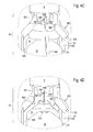
- the air guide assembly 1 first variant is arranged, which initially consists essentially of a cylindrical chamber 10 surrounded by a jacket 13 , at its lower first end 101, a tubular connecting piece 11 to the closing body. 7 leads.
- an air valve 16 sets, which in turn is connected to the lower end of the valve rod 8 .
- the air valve 16 has a primary part 160 , which represents the connection between the valve rod 8 and the second chamber end 102 .
- the primary part 160 has in the interior of the risers 92 , 93 opening openings 161st
- the valve function of the end body 7 is created by the interaction of valve seal 71 mounted on the end body 7 and the valve seat 70 present on the lower riser 93 .
- a coarse filter 75 is arranged to protect the air guide assembly 1 from mechanical damage.
- FIGS. 1C to 1F normal state
- the float 15 is provided with the seal 151 for closing the inner mouth of the third flow passage 168 .
- the secondary part 165 sits sealed in the second flow passage 162 of the primary part 160.
- the chamber 10 has the cylindrical chamber jacket 13 with the inner surface 130th Between the inner surface 130 of the chamber jacket 13 and the float 15 guided in the chamber 10 , the flow gap 14 remains.
- the float 15 has outer elements 150 , which serve to guide the float 15 in the chamber 10 while maintaining the flow gap 14 .
- the secondary part 165 of the air valve 16 has first support elements 166, which serve to guide the chamber 10 and the positioning on the float 15 .
- second support elements 167 are provided for positioning in the second flow passage 162 .
- the air guide assembly 1 is on the one hand rigidly connected to the closing body 7 and on the other hand rigidly connected to the valve body 8 intended for actuating the closing body 7 .
- the opening 911 on the hose connection 910 on the attachment tube 91 is preferably provided with a sieve and / or filter.
- Such Spray water would flow through the riser 93 of the drainage opening 77 , which otherwise serves to empty the hydrant 9 after use with the closing body 7 closed again.
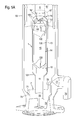
- FIGS. 4A to 4D (automatic operating ventilation)
- the flow gap 14 between the shell inner surface 130 and the float 15 is so far filled with a passing through the first flow passage 76 of the end body 7 air volume 12 from the conduit network 97 that the float 15 undergoes reduced buoyancy, with its seal 151, the inner mouth of the third Flow passage 168 at the secondary part 165 of the air valve 16 releases, while the secondary part 165 by the prevailing pressure conditions in the primary part 160 , the second flow passage 162 is closed, inserted and the air volume 12 escapes through the third flow passage 168 . From here, the air volume 12 passes through the opening 161 in the primary part 160 in the upper riser 92 to the opening 911 on the hydrant 9 to flow into the atmosphere. Eventually by the third Flow passage 168 spraying spray water flows through the lower riser 93 to the drainage opening 77 and exits into the soil.
- a negative pressure which continues from the line network 97 through the first flow passage 76 of the end body 7 , is established in relation to the atmosphere.
- the float 15 sinks in the chamber 10
- the secondary part 165 moves through the prevailing pressure conditions from the primary part 160 and thus releases the second flow passage 162 free.
- air from the atmosphere via the opening 911 at the hose connection 910 through the top tube 91 and the upper riser 92 , the opening 161 and the second flow passage 162 in the primary part 160 , the flow gap 14 in the chamber 10 and the first flow passage 76 in the closing body. 7 to get into the network of lines 97 to compensate for the resulting from the accident vacuum.
- the device In this state, with the float 15 lowered to the first end of the chamber 101 and the secondary part 165 pushed out of the primary part 160 , the device is also in the delivery state or before being put into operation.
- FIGS. 6A to 8B normal state
- the air guide assembly 1 is shown unsealed and sealed in the second to fourth variant , starting from the ongoing operation of the line network 97 (s. Figures 1C-1F ).
- the closing body 7 is in the closed valve position and the air guide assembly 1 in the normal state, ie there is no automatic operating ventilation of the line network 97 (s. Figures 4A-4D ).
- the in case of emergency automatically operated ventilation of the network 97 (s. Figures 5A-5D ) is only possible in the unsealed situation described later.
- the air guide assembly 1 in the second to fourth variant causes, for example, as a result of flooding in the hydrant 9 pending contaminated water, which could reach via the drainage hole 77 in the lower riser 93 in the hydrant 9 , can not flow into the network 97 .
- FIG. 6B (unsealed)
- the buoyancy body 17 is of annular shape, which preferably consists of plastic, with its outer periphery quasi flush with the shell 13 and in the absence of buoyancy on the inclined surface of the primary part 160 - adjacent the upper chamber end 102nd - sits up.
- the shoulder portion 170 At the top of the buoyant body 17 has the shoulder portion 170 , on which the ring seal 171 sits.
- FIG. 6C (sealed)
- the buoyant body 17 is formed as the shell 13 outside umhüllender and axially upwardly moving in buoyancy hollow cylinder.
- the buoyant body 17 has at the top the shoulder portion 170 , in which the ring seal 171 sits.
- an open gap between the ring seal 171 and the free end of the collar 164 (s. FIG. 7A ).
- the gap between the ring seal 171 and the free end of the collar 164 is closed when the buoyant body 17 is raised (see FIG. FIG. 7B ), so that no contaminated water from the hydrant 9 can get into the network 97 .
- the buoyant body 17 is made according to the annular segment Figures 6A-6C and the hollow cylinder according to FIGS. 7A + 7B together.
- the ring seal 171 sits on top of the shoulder portion 170 of the annular segment.
- an open gap between the annular seal 171 and the free end of the collar 164 remains, in the case of a buoyant body 17 lowered by gravity (see FIG. Figure 8A ).
- Due to the thus enlarged volume of this buoyant body 17 the seal between the ring seal 171 and the free end of the collar 164 intensifies when buoyant body 17 is lifted by increased buoyancy.
- the gap between ring seal 171 and collar 164 has closed; it can not get contaminated water from the hydrant 9 in the pipe network 97 (s. FIG. 8B ).
- the secondary part 165 of the air valve 16 with the first support elements 166 is accommodated on the float 15 in an axially limited manner. Projecting lugs 169 of the first support elements 166 engage in a diameter constriction 153 on the float 15 , which ends at the top of a radially projecting annular shoulder 152 .
- the secondary part 165 has below the seal 163 lying above the annular shoulder 152 , distributed over the circumference in sections annular gap S.
- the annular gap S serves as a filter to retain contaminants that rinsed in the water through the first flow passage 76 of the end body 7 in the flow gap 14 become.
- the automatic ventilation (s. FIG. 9C ) is activated when a negative pressure arises in the line network 97 .
- the float 15 decreases, and at the same time moves the secondary part 165 from the primary part 160 downwards until the lugs 169 come to lie virtually at the bottom stop within the diameter constriction 153 .
- the second flow passage 162 is open so that atmospheric air can be sucked into the conduit network 97 via the openings 161 .
- the air guide assembly 1 of the sixth variant can be operated only in the normal state and with automatic ventilation.
- the second flow passage 162 is omitted here.
- the secondary part 165 is immovably fixedly connected to the primary part 160 .
- a disc-shaped abutment 190 is arranged, on whose underside a spring 19 is supported.
- This spring 19 acts on a spherical shut-off element 18 , which closes the third flow passage 168 , so that a check valve is formed.
- the upwardly directed second support element 167 forms a vertical guide for the shut-off element 18 .
- the float 15 is lowered in the chamber 10 , the secondary 165 sits on the float 15 , and the second flow passage 162 is open.
- the air driven from the conduit network 97 through the first flow passage 76 of the end body 7 into the chamber 10 can flow out through the second flow passage 162 , the aperture 161 , the upper riser 92 and the attachment tube 91 via the opening 911 into the atmosphere.
- the removal of spray water injected via the first flow passage 76 and the connecting piece 11 into the chamber 15 via the second flow passage 162 , the opening 161 and down in the lower riser 93 to the drainage opening 77 is relevant.
- the process is slightly different. Initially, the float 15 is again lowered by gravity into the chamber 10 and is thus spaced from the stationary secondary 165. The float seal 151 releases entry into the third flow passage 168 , however, the shut-off element 18 initially closes the outlet of the flow passage 168 .
- the increasing pressure of the discharged from the mains network 97 air volume causes a lifting of the shut-off element 18 of Outlet of the flow passage 168 against the spring 19 , so that the air volume 12 via the outlet A in the second support member 167 and the openings 161 in the primary part 160 can flow into the atmosphere.
Landscapes
- Health & Medical Sciences (AREA)
- Life Sciences & Earth Sciences (AREA)
- Engineering & Computer Science (AREA)
- Hydrology & Water Resources (AREA)
- Public Health (AREA)
- Water Supply & Treatment (AREA)
- Self-Closing Valves And Venting Or Aerating Valves (AREA)
Abstract
Description
Die Erfindung betrifft eine Vorrichtung zur Luftführung an einem sich im Gelände unterirdisch erstreckenden Wasserleitungsnetz. Eine Entlüftung des Leitungsnetzes ist bei der erstmaligen oder erneuten Inbetriebnahme erforderlich sowie während des laufenden Betriebs nötig, um nachgeschaltete Armaturen sowie angeschlossene Geräte vor Defekten zu schützen und deren Betriebssicherheit zu garantieren. Eine Belüftung des Wasserleitungsnetzes ist zur Verhütung eines massiven Schadens angebracht, nämlich im Havariefall - bei grossem Leck oder Bruch im Leitungsnetz - oder bei gewollter Entleerung des Leitungsnetzes, wenn dadurch gegenüber der Atmosphäre ein Unterdruck mit der Gefahr der Leitungsimplosion entstehen würde.The invention relates to a device for guiding air on an underground water network extending in the area. Ventilation of the pipeline network is required during initial or renewed commissioning and during operation to protect downstream valves and connected devices against defects and to guarantee their operational safety. Aeration of the water supply network is appropriate for preventing massive damage, namely in the event of a disaster - in the event of a major leak or breakage in the pipeline network - or if the pipeline network is intentionally emptied, as a result of which a negative pressure with the risk of line implosion would arise with respect to the atmosphere.
Die Entlüftung des Wasser führenden, unterirdisch verlegten Leitungsnetzes wird bei erstmaliger oder erneuter Inbetriebnahme üblicherweise durch Öffnen der im näheren Umfeld stehenden Hydranten durchgeführt. Für den Havariefall bei Leitungsbruch zur Vermeidung einer Leitungsimplosion mit hohen Schäden sowie zur automatischen Betriebsentlüftung des Leitungsnetzes sind Be- und Entlüftungsgeräte, z.B. von der Hawle Armaturen GmbH, D-83395 Freilassing /Deutschland, bekannt (siehe deren Homepage unter www.hawle.de/produkte/be-und entlueftungsventile-garnituren-spuelarmaturen). Diese Gerätschaften verursachen bereits erhebliche Anschaffungs- und Installationskosten. Die Unterbringung erfolgt zumeist in unterirdisch anzulegenden Schächten. Neben dem zusätzlichen Wartungsaufwand sind die Geräte auch vom hygienischen Standpunkt nicht optimal, da beim Belüften des Leistungsnetzes kaum saubere Luft angesaugt wird. Bei oberirdisch angelegten Schächten entfällt das Hygieneproblem, jedoch sind solche Schächte für die Zugänglichkeit zur Wartung der Geräte voluminös zu bemessen und stellen ein Hindernis in der Raumplanung dar. Daher werden Installationen mit sich bis oberirdisch erstreckenden Schächten nur in geringer Anzahl, üblicherweise in der Nähe von Reservoirs oder anderen Hochpunkten, vorgesehen.The venting of the underground, underground water supply network is usually carried out at first or re-commissioning by opening the nearby hydrant hydrant. For the accident case of line break to avoid a line implosion with high damage as well as for the automatic operation venting of the line network, ventilation devices, eg from Hawle Armaturen GmbH, D-83395 Freilassing / Germany, are known (see their homepage under www.hawle.de/ products / valves and valves for cleaning valves. These equipment already cause considerable purchase and installation costs. Accommodation is usually in underground shafts. In addition to the additional maintenance, the devices are also not optimal from a hygienic standpoint, since when airing the power network hardly clean air is sucked. Above-ground manholes eliminate the hygiene problem, however, such manholes for accessibility to the maintenance of the equipment are voluminous to dimension and represent an obstacle in the spatial planning. Therefore, installations with shafts extending to above-ground only in small numbers, usually near reservoirs or other high points.
Angesichts der erheblichen Nachteile der bisher am Markt erhältlichen Geräte und Installationen liegt der Erfindung die Aufgabe zugrunde, eine technisch und hygienisch verbesserte und dabei kosteneffizientere Vorrichtung zur Luftführung an einem sich im Gelände unterirdisch bereits erstreckenden oder neu konzipierten Wasserleitungsnetz zu schaffen. Hierbei umfasst die Luftlenkung zumindest das Entlüften des Wasserleitungsnetzes. Eine weiter ausgestaltete Vorrichtung soll auch eine Luftlenkung in entgegengesetzter Flussrichtung, nämlich zur Belüftung des Wasserleitungsnetzes, ermöglichen.In view of the considerable disadvantages of the devices and installations available on the market, the invention has for its object to provide a technically and hygienically improved and more cost-effective device for guiding air on an underground already existing or newly designed water supply network. In this case, the air control system comprises at least venting the water supply network. A further configured device should also allow air guidance in the opposite direction of flow, namely for ventilation of the water supply network.
Die zur Luftführung eines sich im Gelände unterirdisch erstreckenden Wasserleitungsnetzes konzipierte Vorrichtung hat eine in einem Hydranten integrierte Luftführungs-Baugruppe, die zum automatischen Luftabfluss in die Atmosphäre durch den Hydranten der diesem aus dem Wasserleitungsnetz zugeflossenen aufgestauten Luft bestimmt ist.The device designed for guiding the air of an underground water supply network has a hydrant-integrated air duct assembly, which is intended for the automatic discharge of air into the atmosphere through the hydrant of the dammed air supplied to it from the water supply network.
Nachstehend sind besonders vorteilhafte Details zur Vorrichtung genannt. Die Luftführungs-Baugruppe ist in einem Steigrohr des Hydranten eingebaut und umfasst:
- a) eine Kammer mit einem ersten Kammerende, das mit einem ersten Strömungsdurchgang verbunden ist, welcher sich durch einen ein Ventil bildenden Abschlusskörper des Hydranten erstreckt und zum Wasserleitungsnetz führt;
- b) ein Luftventil, das an einem zweiten Kammerende angeordnet ist; und
- c) einen Schwimmer, der in der Kammer zwischen dem ersten Kammerende und dem zweiten Kammerende beweglich geführt ist.
- a) a chamber having a first chamber end which is connected to a first flow passage which extends through a hydrant forming a valve closing body and leads to the water pipe network;
- b) an air valve disposed at a second chamber end; and
- c) a float which is movably guided in the chamber between the first chamber end and the second chamber end.
Die Luftführungs-Baugruppe ist einerseits starr mit dem Abschlusskörper und andererseits starr mit einer zur Betätigung des Abschlusskörpers bestimmten Ventilstange verbunden.The air guide assembly is on the one hand rigidly connected to the closing body and the other rigidly connected to a particular valve body for actuating the closing body.
Das Luftventil umfasst:
- a) ein Primärteil, das am zweiten Kammerende fest angeordnet ist und einen zweiten Strömungsdurchgang hat; und
- b) ein Sekundärteil, das zwischen dem Primärteil und dem Schwimmer beweglich angeordnet ist und einen dritten Strömungsdurchgang hat; wobei
- c) der dritte Strömungsdurchgang eine innere, zum Schwimmer weisende, Mündung und eine äussere, mit der Atmosphäre verbundene, Mündung besitzt.
- a) a primary part fixedly disposed at the second chamber end and having a second flow passage; and
- b) a secondary part movably disposed between the primary part and the float and having a third flow passage; in which
- c) the third flow passage has an inner mouth facing the float and an outer mouth connected to the atmosphere.
Der Schwimmer ist mit einer Dichtung zum Verschliessen der inneren Mündung des dritten Strömungsdurchgangs versehen. Das Sekundärteil passt abgedichtet in den zweiten Strömungsdurchgang des Primärteils. Die Kammer hat einen zylindrischen Kammermantel mit einer Innenfläche. Zwischen der Innenfläche des Kammermantels und dem in der Kammer geführten Schwimmer verbleibt ein Strömungsspalt. Der Schwimmer besitzt Aussenelemente, die zur Führung des Schwimmers in der Kammer mit Beibehaltung des Strömungsspalts dienen. Das Sekundärteil des Luftventils hat erste Stützelemente, die der Führung in der Kammer und der Positionierung auf dem Schwimmer dienen, und am Sekundärteil sind zweite Stützelemente zur Positionierung im zweiten Strömungsdurchgang vorgesehen.The float is provided with a seal for closing the inner mouth of the third flow passage. The secondary part fits sealed into the second flow passage of the primary part. The chamber has a cylindrical chamber jacket with an inner surface. Between the inner surface of the chamber shell and the float guided in the chamber remains a flow gap. The float has external elements which serve to guide the float in the chamber while maintaining the flow gap. The secondary part of the air valve has first support elements which serve to guide the chamber and to position it on the float, and second abutment elements are provided on the secondary part for positioning in the second flow passage.
Während des laufenden Betriebs des Leitungsnetzes, mit dem Abschlusskörper in geschlossener Ventilstellung, ergeben sich folgende Situationen:During operation of the pipeline network, with the closing body in the closed valve position, the following situations arise:
- a) Der Strömungsspalt zwischen der Mantelinnenfläche der Kammer und dem Schwimmer ist so weit mit durch den ersten Strömungsdurchgang des Abschlusskörpers gelangtem Wasser aus dem Leitungsnetz gefüllt, dass der Schwimmer auftriebsbedingt mit seiner Dichtung die innere Mündung des dritten Strömungsdurchgangs am Sekundärteil des Luftventils verschliesst; unda) The flow gap between the shell inner surface of the chamber and the float is so far filled with the first flow passage of the end body water from the mains network filled that the float buzzing closes with its seal, the inner mouth of the third flow passage on the secondary part of the air valve; and
- b) das Sekundärteil in das Primärteil, dessen zweiten Strömungsdurchgang verschliessend, eingeschoben ist.b) the secondary part in the primary part, the second flow passage is closed, inserted.
- a) Der Strömungsspalt zwischen der Mantelinnenfläche und dem Schwimmer ist so weit mit einem durch den ersten Strömungsdurchgang des Abschlusskörpers gelangten Luftvolumen aus dem Leitungsnetz gefüllt, dass der Schwimmer verminderten Auftrieb erfährt;a) The flow gap between the shell inner surface and the float is so far filled with an reached by the first flow passage of the closing body volume of air from the conduit network that the float undergoes reduced buoyancy;
- b) die Dichtung gibt die innere Mündung des dritten Strömungsdurchgangs am Sekundärteil des Luftventils frei; dabei ist das Sekundärteil durch die herrschenden Druckverhältnisse in das Primärteil, dessen zweiten Strömungsdurchgang verschliessend, eingeschoben; undb) the seal releases the inner orifice of the third flow passage at the secondary part of the air valve; In this case, the secondary part by the prevailing pressure conditions in the primary part, the second flow passage closing, inserted; and
- c) das Luftvolumen strömt durch den dritten Strömungsdurchgang über eine Öffnung am Hydranten in die Atmosphäre ab; wobeic) the air volume flows through the third flow passage through an opening on the hydrant into the atmosphere; in which
- d) die Öffnung am Hydranten vorzugsweise oberhalb des Erdniveaus vorgesehen ist.d) the opening on the hydrant is preferably provided above the earth level.
Bei erstmaliger oder erneuter Inbetriebnahme des Leitungsnetzes, mit dessen sukzessiver Befüllung und dem Abschlusskörper in geschlossener Ventilstellung, ergibt sich für eine Startentlüftung folgende Situation:
- a) anfänglich ist der Schwimmer aufgrund seiner Schwerkraft in der Kammer abgesenkt, das Sekundärteil sitzt auf dem Schwimmer auf und der zweite Strömungsdurchgang ist offen, so dass die aus dem Leitungsnetz durch den ersten Strömungsdurchgang des Abschlusskörpers in die Kammer getriebene Luft durch den zweiten Strömungsdurchgang über die Öffnung am Hydranten in die Atmosphäre abströmt; und schliesslich
- b) durch den in der Kammer sukzessive ansteigenden Wasserstand bei darin aufsteigendem Schwimmer das restliche Luftvolumen aus der Kammer durch das Luftventil über die Öffnung am Hydranten in die Atmosphäre abgeströmt ist, bis das Sekundärteil vom Schwimmer in den zweiten Strömungsdurchgang des Primärteils eingeschoben ist, somit den zweiten Strömungsdurchgang verschliesst, und die Schwimmerdichtung auch den dritten Strömungsdurchgang verschliesst.
- a) initially, the float is lowered by gravity in the chamber, the secondary part sits on the float and the second flow passage is open, so that the driven from the conduit network through the first flow passage of the closing body in the chamber through the second air flow passage over the opening on the hydrant flows into the atmosphere; and finally
- b) by the gradually rising in the chamber water level with it rising float the remaining air volume has flowed out of the chamber through the air valve through the opening on the hydrant into the atmosphere until the secondary part is inserted from the float in the second flow passage of the primary part, thus the closes the second flow passage, and the float seal also closes the third flow passage.
Das Steigrohr und die Ventilstange führen zu einem Aufsatzrohr, an welchem die Öffnung vorgesehen ist, wobei:
- a) der Öffnung am Aufsatzrohr ein Sieb und/oder ein Filter vorgesetzt ist; oder
- b) das Aufsatzrohr zumindest einen Schlauchanschluss hat, an dem die Öffnung liegt, und damit der Hydrant die Gestalt eines Überflurhydranten erhält, wobei ein Sieb und/oder ein Filter in der Öffnung oder in einer auf den Schlauchanschluss aufsetzbaren Abdeckung angeordnet sein können;
- c) vor dem Eintritt aus dem Leitungsnetz in den ersten Strömungsdurchgang ein Grobfilter zum Schutz der Luftführungs-Baugruppe vor mechanischer Beschädigung angeordnet ist; und
- d) ein Anschlussstück vom ersten Kammerende zum ersten Strömungsdurchgang führt.
- a) a sieve and / or a filter is placed before the opening on the attachment tube; or
- b) the attachment pipe has at least one hose connection at which the opening is located, and thus the hydrant is in the form of a above-ground hydrant, wherein a screen and / or a filter can be arranged in the opening or in a cover which can be placed on the hose connection;
- c) a coarse filter to protect the air duct assembly from mechanical damage is arranged before entering the line network in the first flow passage; and
- d) a fitting leads from the first end of the chamber to the first flow passage.
Bei Vorhandensein des zweiten Strömungsdurchgangs ist oberhalb dessen ein Durchbruch vorhanden, welcher dem Durchtritt von Luft und/oder Gischtwasser dient. Das Gischtwasser fliesst im Steigrohr einer Entwässerungsöffnung zu, welche vorzugsweise ansonsten der Entleerung des Hydranten nach Gebrauch bei wieder geschlossenem Abschlusskörper dient. Die Luftführungs-Baugruppe hat einen beweglichen Auftriebskörper, der dazu bestimmt ist, bei sich im unteren Steigrohr ansammelnden Wasser aufzusteigen und den Eintritt in den Durchbruch zu versperren, um zu verhindern, dass solches Wasser in das Leitungsnetz gelangen kann.In the presence of the second flow passage above which an opening is present, which serves for the passage of air and / or spray water. The gisch water flows in the riser to a drainage opening, which preferably otherwise serves the emptying of the hydrant after use in again closed end body. The air guide assembly has a floating buoyant body designed to ascend water accumulating in the lower riser and to block entry into the breakthrough to prevent such water from entering the conduit network.
Der Auftriebskörper:
- a) ist im Prinzip ein das Primärteil umgebender Kreisring; oder
- b) ist als den Kammermantel aussen umhüllender Hohlzylinder ausgebildet; oder
- c) setzt sich aus dem Kreisring und dem Hohlzylinder zusammen; und
- d) ist auf seiner Schulterpartie mit einer Ringdichtung versehen, die bei aufgestiegenem Auftriebskörper mit einem sich vom Primärteil erstreckenden Kragen eine dichte Absperrung vor dem Eintritt in den Durchbruch bildet.
- a) is in principle a circular ring surrounding the primary part; or
- b) is formed as the outer shell enclosing hollow cylinder; or
- c) is composed of the circular ring and the hollow cylinder; and
- d) is provided on its shoulder with a ring seal, which forms a sealed barrier before entering the breakthrough with ascending buoyancy body with a collar extending from the primary part.
Der Hydrant ist im Wasserleitungsnetz, in Bezug auf das Normalnull, vorzugsweise an einer Stelle erhöhten Niveaus installiert, der Luft aus dem Wasserleitungsnetz zufliesst und sich dort sammelt. Die Vorrichtung mit der Luftführungs-Baugruppe ist an einem bestehenden Hydranten nachrüstbar.The hydrant is installed in the aqueduct, with respect to the normal zero, preferably at an elevated level, which fills and collects air from the water mains. The device with the air guide assembly can be retrofitted to an existing hydrant.
Die im Hydranten integrierte Luftführungs-Baugruppe ist, zusätzlich zum automatischen Luftabfluss in die Atmosphäre durch den Hydranten der diesem aus dem Wasserleitungsnetz zugeflossenen aufgestauten Luft, auch zum automatischen Luftzufluss aus der Atmosphäre durch den Hydranten in das Wasserleitungsnetz bei im Wasserleitungsnetz auftretendem Unterdruck bestimmt.The integrated hydrant air duct assembly is, in addition to the automatic air flow into the atmosphere through the hydrant of this from the water supply network accumulated air, also intended for automatic air flow from the atmosphere through the hydrant into the water network at low pressure occurring in the water network.
Während des laufenden Betriebs des Leitungsnetzes, mit dem Abschlusskörper in geschlossener Ventilstellung, und bei automatischer Belüftung im Havariefall infolge eines Lecks oder durch gewollte Entleerung des Leitungsnetzes ergibt sich folgende Situation:
- a) im Strömungsspalt stellt sich gegenüber der Atmosphäre ein aus dem Leitungsnetz durch den ersten Strömungsdurchgang des Abschlusskörpers fortgesetzter Unterdruck ein;
- b) der Schwimmer sinkt in der Kammer;
- c) das Sekundärteil fährt durch die herrschenden Druckverhältnisse aus dem Primärteil und gibt dessen zweiten Strömungsdurchgang frei; und
- d) somit gelangt Luft aus der Atmosphäre über die Öffnung am Hydranten durch den zweiten Strömungsdurchgang, die Kammer und den ersten Strömungsdurchgang im Abschlusskörper in das Leitungsnetz.
- a) in the flow gap sets against the atmosphere a continued from the line network through the first flow passage of the closing body negative pressure;
- b) the float sinks in the chamber;
- c) the secondary part moves through the prevailing pressure conditions from the primary part and releases its second flow passage; and
- d) thus air from the atmosphere passes through the opening at the hydrant through the second flow passage, the chamber and the first flow passage in the end body into the conduit network.
Die ersten Stützelemente weisen zentrisch zum Schwimmer hin gerichtete vorspringende Nasen auf, die in eine Durchmesserverengung am Schwimmer eingreifen. Die Durchmesserverengung endet oben an einer radial überstehenden Ringschulter, die als Aufhängung bei abgesunkenem Schwimmer wirkt. Das Sekundärteil hat einen oberhalb der Ringschulter liegenden, über den Umfang abschnittsweise verteilten Ringspalt, der als Filter dient, um Verunreinigungen zurückzuhalten.The first support elements have centrally projecting towards the float projecting lugs, which engage in a diameter constriction on the float. The diameter constriction ends at the top of a radially projecting annular shoulder, which acts as a suspension with sunken float. The secondary part has an annular gap lying above the annular shoulder and distributed over the circumference in sections, which serves as a filter in order to retain impurities.
Alternativ umfasst das Luftventil:
- a) ein Primärteil, das am zweiten Kammerende fest angeordnet ist und einen Durchbruch hat, der in die Atmosphäre führt;
- b) ein Sekundärteil, das integraler Bestandteil des Primärteils oder mit diesem fest verbunden ist und einen dritten Strömungsdurchgang hat;
- c) am dritten Strömungsdurchgang eine innere, zum Schwimmer weisende Mündung und eine äussere, mit der Atmosphäre verbundene Mündung;
- d) oben am Primärteil ein Widerlager, an dem sich eine Feder abstützt, welche auf ein Absperrelement wirkt, das den dritten Strömungsdurchgang verschliesst, so dass ein Rückschlagventil entsteht; wobei
- e) sich das Rückschlagventil bei definiertem Druck des in die Luftführungs-Baugruppe aus dem Wasserleitungsnetz zugeflossenen aufgestauten Luftvolumens für den automatischen Luftabfluss in die Atmosphäre durch den Hydranten öffnet.
- a) a primary part, which is fixedly disposed at the second end of the chamber and has a breakthrough, which leads to the atmosphere;
- b) a secondary part which is integral with or integral with the primary part and has a third flow passage;
- c) at the third flow passage, an inner mouth facing the float and an outer mouth connected to the atmosphere;
- d) at the top of the primary part of an abutment on which a spring is supported, which acts on a shut-off, which closes the third flow passage, so that a check valve is formed; in which
- e) opens the check valve at a defined pressure of accumulated in the air guide assembly from the water network accumulated air volume for the automatic air outflow into the atmosphere through the hydrant.
Es zeigen:
- Figur 1A -
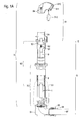
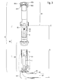
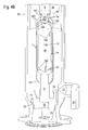
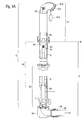
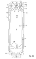
- einen im Gelände installierten Hydranten, in Gestalt eines Überflurhydranten mit Aufsatzrohr, oberem Steigrohr, darunter angeordnetem unterem Steigrohr und Einlaufbogen, mit angeschlossener Zuleitung und Weiterführung zum Leitungsnetz, mit dem Abschlusskörper in geschlossener Ventilstellung, als Teilschnitt;
- Figur 1B -
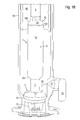
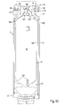
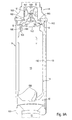
- das vergrösserte Detail X1 aus den
Figuren 1A und3 ; - Figur 1C -
- die Darstellung gemäss
Figur 1B , mit der Luftführungs-Baugruppe in einer ersten Variante im Normalzustand, im Teilschnitt durch Abschlusskörper und Luftführungs-Baugruppe; - Figur 1D -
- die Darstellung gemäss
Figur 1C im Schnitt durch das Luftventil der Luftführungs-Baugruppe erster Variante; - Figur 1E -
- das vergrösserte Detail X2 aus
Figur 1C ; - Figur 1F -
- das vergrösserte Detail X3 aus
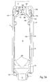
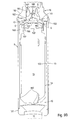
Figur 1 D; - Figur 2A -
- die Darstellung gemäss
Figur 1A , mit dem Abschlusskörper in offener Ventilstellung, als Teilschnitt; - Figur 2B -
- das vergrösserte Detail X4 aus
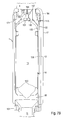
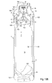
Figur 2A ; - Figur 3 -
- die Darstellung gemäss
Figur 1A , mit einem modifizierten Aufsatzrohr, als Teilschnitt; - Figur 4A -
- die Darstellung gemäss
Figur 1C , mit der Luftführungs-Baugruppe erster Variante bei automatischer Betriebsentlüftung, im Teilschnitt durch Abschlusskörper und Luftführungs-Baugruppe; - Figur 4B -
- die Darstellung gemäss
Figur 3A im Schnitt durch das Luftventil der Luftführungs-Baugruppe erster Variante; - Figur 4C -
- das vergrösserte Detail X5 aus
Figur 4A ; - Figur 4D -
- das vergrösserte Detail X6 aus
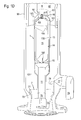
Figur 4B ; - Figur 5A -
- die Darstellung gemäss
Figur 1C , mit der Luftführungs-Baugruppe erster Variante bei automatischer Belüftung im Havariefall, im Teilschnitt durch Abschlusskörper und Luftführungs-Baugruppe; - Figur 5B -
- die Darstellung gemäss
Figur 5A im Schnitt durch das Luftventil der Luftführungs-Baugruppe erster Variante; - Figur 5C -
- das vergrösserte Detail X7 aus
Figur 5A ; - Figur 5D -
- das vergrösserte Detail X8 aus
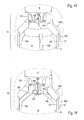
Figur 5B ; - Figur 6A -
- die Darstellung gemäss
Figur 1A , mit der Luftführungs-Baugruppe zweiter Variante, als Teilschnitt; - Figur 6B -
- das vergrösserte Detail X9 aus
Figur 6A , mit der Luftführungs-Baugruppe zweiter Variante im Normalzustand, unabgedichtet, als Teilschnitt; - Figur 6C -
- die Darstellung gemäss
Figur 6B , im Normalzustand, abgedichtet, als Teilschnitt; - Figur 7A -
- das vergrösserte Detail X9 aus
Figur 6A , mit der Luftführungs-Baugruppe dritter Variante im Normalzustand, unabgedichtet, als Teilschnitt; - Figur 7B -
- die Darstellung gemäss
Figur 7A , im Normalzustand, abgedichtet, als Teilschnitt; - Figur 8A -
- das vergrösserte Detail X9 aus
Figur 6A , mit der Luftführungs-Baugruppe vierter Variante im Normalzustand, unabgedichtet, als Teilschnitt; - Figur 8B -
- die Darstellung gemäss
Figur 7A , im Normalzustand, abgedichtet, als Teilschnitt; - Figur 9A -
- das vergrösserte Detail X1 aus
Figur 1A mit der Luftführungs-Baugruppe fünfter Variante im Normalzustand, als Teilschnitt; - Figur 9B -
- die Darstellung gemäss
Figur 9A , mit der Luftführungs-Baugruppe bei automatischer Betriebsentlüftung, als Teilschnitt; - Figur 9C -
- die Darstellung gemäss
Figur 9A , mit der Luftführungs-Baugruppe bei automatischer Belüftung im Havariefall, als Teilschnitt; - Figur 10A -
- das vergrösserte Detail X1 aus
Figur 1A mit der Luftführungs-Baugruppe sechster Variante im Normalzustand, als Teilschnitt; und - Figur 10B -
- die Darstellung gemäss
Figur 10A , mit der Luftführungs-Baugruppe bei automatischer Betriebsentlüftung, als Teilschnitt.
- Figure 1A -
- a hydrant installed in the field, in the form of an above-ground hydrant with attachment tube, upper riser, below arranged lower riser and inlet bend, with connected supply and continuation to the network, with the closing body in the closed valve position, as a partial section;
- FIG. 1B -
- the enlarged detail X1 from the
Figures 1A and3 ; - FIG. 1C
- the representation according to
FIG. 1B , with the air guide assembly in a first variant in the normal state, in partial section through end body and air guide assembly; - FIG. 1D -
- the representation according to
Figure 1C in section through the air valve of the air guide assembly of the first variant; - FIG. 1E -
- enlarged detail X2
Figure 1C ; - FIG. 1F -
- enlarged detail X3
FIG. 1 D; - Figure 2A -
- the representation according to
Figure 1A , with the closing body in open valve position, as a partial section; - FIG. 2B -
- enlarged detail X4
FIG. 2A ; - FIG. 3 -
- the representation according to
Figure 1A , with a modified extension tube, as a partial section; - FIG. 4A -
- the representation according to
Figure 1C , with the air duct assembly of the first variant with automatic operating ventilation, in the partial section through the closing body and air duct assembly; - FIG. 4B -
- the representation according to
FIG. 3A in section through the air valve of the air guide assembly of the first variant; - FIG. 4C -
- enlarged detail X5
FIG. 4A ; - FIG. 4D -
- enlarged detail X6
FIG. 4B ; - FIG. 5A
- the representation according to
Figure 1C , with the air duct assembly of the first variant with automatic ventilation in case of an accident, in partial section through end body and air duct assembly; - FIG. 5B -
- the representation according to
FIG. 5A in section through the air valve of the air guide assembly of the first variant; - FIG. 5C -
- enlarged detail X7
FIG. 5A ; - FIG. 5D -
- enlarged detail X8
FIG. 5B ; - FIG. 6A -
- the representation according to
Figure 1A , with the air guide assembly of the second variant, as a partial section; - FIG. 6B -
- enlarged detail X9
FIG. 6A , with the air guide assembly of the second variant in the normal state, unsealed, as a partial section; - FIG. 6C -
- the representation according to
FIG. 6B , in normal condition, sealed, as partial section; - FIG. 7A -
- enlarged detail X9
FIG. 6A , with the air duct assembly third variant in the normal state, unsealed, as a partial section; - FIG. 7B -
- the representation according to
FIG. 7A , in normal condition, sealed, as partial section; - FIG. 8A -
- enlarged detail X9
FIG. 6A , with the fourth version air duct assembly in the normal state, unsealed, as a partial section; - FIG. 8B -
- the representation according to
FIG. 7A , in normal condition, sealed, as partial section; - FIG. 9A -
- enlarged detail X1
Figure 1A with the air duct assembly fifth variant in the normal state, as a partial section; - FIG. 9B -
- the representation according to
Figure 9A , with the air guide assembly with automatic operating ventilation, as a partial section; - FIG. 9C -
- the representation according to
Figure 9A , with the air guide assembly with automatic ventilation in case of accident, as a partial section; - FIG. 10A -
- enlarged detail X1
Figure 1A with the air duct assembly sixth variant in the normal state, as a partial section; and - FIG. 10B
- the representation according to
Figure 10A , with the air guide assembly with automatic operating ventilation, as a partial section.
Mit Bezug auf die beiliegenden Zeichnungen erfolgt nachstehend die detaillierte Beschreibung eines Ausführungsbeispiels zur erfindungsgemässen Vorrichtung zur Be- und/oder Entlüftung eines sich im Gelände unterirdisch erstreckenden Wasserleitungsnetzes am Beispiel eines im Gelände inst allierten und an das Wasserleitungsnetz angeschlossenen Hydranten. Das oberirdisch am Hydranten installierte Aufsatzrohr ist in zwei Varianten ausgebildet.With reference to the accompanying drawings, the following detailed description of an embodiment of the inventive device for loading and / or venting in the area underground water supply network using the example of a land in the all-and connected to the water network hydrant. The top pipe installed above the hydrant is designed in two versions.
Für die gesamte weitere Beschreibung gilt folgende Festlegung. Sind in einer Figur zum Zweck zeichnerischer Eindeutigkeit Bezugsziffern enthalten, aber im unmittelbar zugehörigen Beschreibungstext nicht erläutert, so wird auf deren Erwähnung in vorangehenden oder nachfolgenden Figurenbeschreibungen Bezug genommen. Im Interesse der Übersichtlichkeit wird auf die wiederholte Bezeichnung von Bauteilen in weiteren Figuren zumeist verzichtet, sofern zeichnerisch eindeutig erkennbar ist, dass es sich um "wiederkehrende" Bauteile handelt.The following definition applies to the entire further description. If reference numerals are included in a figure for the purpose of graphic clarity, but are not explained in the directly associated description text, reference is made to their mention in the preceding or following description of the figures. In the interest of clarity, the repeated designation of components in other figures is usually dispensed with, as far as the drawing clearly shows that they are "recurring" components.
Der Hydrant 9 - im dargestellten Beispiel ein herkömmlicher Überflurhydrant - hat zuoberst das Aufsatzrohr 91, welches sich über das Erdniveau E in die Höhe erstreckt. Das Aufsatzrohr 91 hat die üblichen Bauteile, wie Verschlusskappe und Schlauchanschluss 910, an dem die Öffnung 911 zum Wasseraustritt mündet. Bei Nichtgebrauch sind der Schlauchanschluss 910 und die Öffnung 911 üblicherweise mit einer aufsetzbaren Abdeckung 912 geschützt. Am Aufsatzrohr 91 ist ferner eine Spindelverlängerung 84 zur Betätigung des Abschlusskörpers 7 mit seiner Ventilfunktion zugänglich. An das Aufsatzrohr 91 schliesst sich das obere Steigrohr 92 an, in dem die an sich bekannten Bauteile, wie Spindellager 83, Spindel 82 und Spindelmutter 81 angeordnet sind. Von der Spindelmutter 81 erstreckt sich die Ventilstange 8 abwärts. Das obere Steigrohr 92 steckt teleskopisch in der Höhe verstellbar im unteren Steigrohr 93, um den Hydranten 9 an die an der jeweiligen Örtlichkeit gegebene Grabentiefe G anzupassen, welche als Abstand zwischen dem Erdniveau E und der Unterkante der mittels des Schraubrings 95 am Einlaufbogen 94 angeschlossenen Zuleitung 96 definiert ist. Das Prinzip eines solchen höhenverstellbaren Hydranten ist Gegenstand der
Zwischen dem unteren Ende der Ventilstange 8 und dem Abschlusskörper 7 ist die Luftführungs-Baugruppe 1 erster Variante angeordnet, welche zunächst im wesentlichen aus einer von einem Mantel 13 umgebenen zylindrischen Kammer 10 besteht, an deren unterem ersten Ende 101 ein rohrförmiges Anschlussstück 11 zum Abschlusskörper 7 führt. An das obere zweite Kammerende 102 setzt ein Luftventil 16 an, das seinerseits mit dem unteren Ende der Ventilstange 8 verbunden ist. Das Luftventil 16 weist ein Primärteil 160 auf, welches die Verbindung zwischen der Ventilstange 8 und dem zweiten Kammerende 102 darstellt. Das Primärteil 160 besitzt in den Innenraum der Steigrohre 92,93 mündende Durchbrüche 161. Die Ventilfunktion des Abschlusskörpers 7 entsteht durch das Zusammenwirken von am Abschlusskörper 7 montierter Ventildichtung 71 und dem am unteren Steigrohr 93 vorhandenen Ventilsitz 70.Between the lower end of the
Bei geschlossener Ventilstellung (s.
Bei offener Ventilstellung (s.
Bei dieser Figurenfolge wird vom laufenden Betrieb des Leitungsnetzes 97 ausgegangen. Der Abschlusskörper 7 befindet sich weiterhin in geschlossener Ventilstellung und die Luftführungs-Baugruppe 1 erster Variante im Normalzustand, d.h. weder läuft eine automatische Betriebsentlüftung des Leitungsnetzes 97 (s.
Die Luftführungs-Baugruppe 1 umfasst:
- a) die
Kammer 10 mitdem ersten Kammerende 101, das mit dem ersten Strömungsdurchgang 76 verbunden ist, welcher sich durch den dasVentil bildenden Abschlusskörper 7 desHydranten 9 erstreckt und zum Wasserleitungsnetz 97 führt; - b)
das Luftventil 16, dasam zweiten Kammerende 102 angeordnet ist; und - c)
den Schwimmer 15, der inder Kammer 10 zwischen erstem Kammerende 101 und zweitem Kammerende 102 beweglich geführt ist.
- a) the
chamber 10 with thefirst chamber end 101 , which is connected to thefirst flow passage 76 which extends through theclosing body 7 forming the valve of thehydrant 9 and leads to thewater network 97 ; - b) the
air valve 16 located at thesecond chamber end 102 ; and - c) the
float 15 , which is movably guided in thechamber 10 between thefirst chamber end 101 and thesecond chamber end 102 .
Das Luftventil 16 umfasst:
- a)
das Primärteil 160, dasam zweiten Kammerende 102 fest angeordnet ist und den zweitenStrömungsdurchgang 162 hat; und - b)
das Sekundärteil 165,das zwischen Primärteil 160und Schwimmer 15 beweglich angeordnet ist undden dritten Strömungsdurchgang 168 hat; wobei - c) der dritte Strömungsdurchgang 168 die innere,
zum Schwimmer 15 weisende Mündung, und die äussere, mit der Atmosphäre verbundene, Mündung besitzt.
- a) the
primary part 160 , which is fixedly disposed on thesecond chamber end 102 and thesecond flow passage 162 has; and - b) the
secondary part 165, which is arranged movably betweenprimary part 160 and float 15 and has thethird flow passage 168 ; in which - c) the
third flow passage 168 has the inner mouth facing thefloat 15 and the outer mouth connected to the atmosphere.
Der Schwimmer 15 ist mit der Dichtung 151 zum Verschliessen der inneren Mündung des dritten Strömungsdurchgangs 168 versehen. Das Sekundärteil 165 sitzt abgedichtet im zweiten Strömungsdurchgang 162 des Primärteils 160. Die Kammer 10 hat den zylindrischen Kammermantel 13 mit der Innenfläche 130. Zwischen der Innenfläche 130 des Kammermantels 13 und dem in der Kammer 10 geführten Schwimmer 15 verbleibt der Strömungsspalt 14. Der Schwimmer 15 besitzt Aussenelemente 150, die zur Führung des Schwimmers 15 in der Kammer 10 mit Beibehaltung des Strömungsspalts 14 dienen. Das Sekundärteil 165 des Luftventils 16 hat erste Stützelemente 166, die der Führung in der Kammer 10 und der Positionierung auf dem Schwimmer 15 dienen. Am Sekundärteil 165 sind zweite Stützelemente 167 zur Positionierung im zweiten Strömungsdurchgang 162 vorgesehen. Die Luftführungs-Baugruppe 1 ist einerseits starr mit dem Abschlusskörper 7 und andererseits starr mit der zur Betätigung des Abschlusskörpers 7 bestimmten Ventilstange 8 verbunden.The
Im jetzigen Normalzustand ist der Strömungsspalt 14 zwischen der Mantelinnenfläche 130 der Kammer 10 und dem Schwimmer 15 so weit mit durch den ersten Strömungsdurchgang 76 des Abschlusskörpers 7 gelangtem Wasser aus dem Leitungsnetz 97 gefüllt, dass der Schwimmer 15 auftriebsbedingt mit seiner Dichtung 151 die innere Mündung des dritten Strömungsdurchgangs 168 am Sekundärteil 165 des Luftventils 16 verschliesst und das Sekundärteil 165 in das Primärteil 160, dessen zweiten Strömungsdurchgang 162 verschliessend, eingeschoben ist. Die Abdichtung wird durch eine im Sekundärteil 165 eingesetzte Dichtung 163 bewirkt, welche gegen das Primärteil 160 drückt.In the current normal state of the
Die Öffnung 911 am Schlauchanschluss 910 am Aufsatzrohr 91 ist vorzugsweise mit einem Sieb und/oder Filter versehen. Oberhalb des zweiten Strömungsdurchgangs 162 ist ein Durchbruch 161 vorhanden, welcher in später zu beschreibenden Betriebszuständen dem Durchtritt von Luft und/oder Gischtwasser dient. Solches Gischtwasser würde durch das Steigrohr 93 der Entwässerungsöffnung 77 zufliessen, welche ansonsten der Entleerung des Hydranten 9 nach Gebrauch bei wieder geschlossenem Abschlusskörper 7 dient.The
In Abwandlung zu den
Bei dieser Figurenfolge wird weiterhin vom laufenden Betrieb des Leitungsnetzes 97 ausgegangen. Der Abschlusskörper 7 befindet sich unverändert in geschlossener Ventilstellung. Mittels der Luftführungs-Baugruppe 1 läuft eine automatische Betriebsentlüftung des Leitungsnetzes 97 ab.In this sequence of figures continues to be based on the ongoing operation of the
Der Strömungsspalt 14 zwischen der Mantelinnenfläche 130 und dem Schwimmer 15 ist so weit mit einem durch den ersten Strömungsdurchgang 76 des Abschlusskörpers 7 gelangten Luftvolumen 12 aus dem Leitungsnetz 97 gefüllt, dass der Schwimmer 15 verminderten Auftrieb erfährt, mit seiner Dichtung 151 die innere Mündung des dritten Strömungsdurchgangs 168 am Sekundärteil 165 des Luftventils 16 freigibt, dabei das Sekundärteil 165 durch die herrschenden Druckverhältnisse in das Primärteil 160, dessen zweiten Strömungsdurchgang 162 verschliessend, eingeschoben ist und das Luftvolumen 12 durch den dritten Strömungsdurchgang 168 entweicht. Von hier gelangt das Luftvolumen 12 durch den Durchbruch 161 im Primärteil 160 in das obere Steigrohr 92 zur Öffnung 911 am Hydranten 9, um in die Atmosphäre abzuströmen. Eventuell durch den dritten Strömungsdurchgang 168 spritzendes Gischtwasser fliesst durch das untere Steigrohr 93 der Entwässerungsöffnung 77 zu und tritt in das Erdreich aus.The
Auch bei dieser Figurenfolge wird weiterhin vom laufenden Betrieb des Leitungsnetzes 97 ausgegangen. Der Abschlusskörper 7 befindet sich in geschlossener Ventilstellung. Mittels der Luftführungs-Baugruppe 1 erster Variante läuft eine automatische Belüftung des Leitungsnetzes 97 im Havariefall, bei Leitungsbruch, ab.Also in this sequence of figures continues to be based on the ongoing operation of the
Im Strömungsspalt 14 stellt sich gegenüber der Atmosphäre ein aus dem Leitungsnetz 97 durch den ersten Strömungsdurchgang 76 des Abschlusskörpers 7 fortgesetzter Unterdruck ein. Somit sinkt der Schwimmer 15 in der Kammer 10, das Sekundärteil 165 fährt durch die herrschenden Druckverhältnisse aus dem Primärteil 160 und gibt damit dessen zweiten Strömungsdurchgang 162 frei. Nun kann Luft aus der Atmosphäre über die Öffnung 911 am Schlauchanschluss 910 durch das Aufsatzrohr 91 und das obere Steigrohr 92, den Durchbruch 161 und den zweiten Strömungsdurchgang 162 im Primärteil 160, den Strömungsspalt 14 in der Kammer 10 und den ersten Strömungsdurchgang 76 im Abschlusskörper 7 bis in das Leitungsnetz 97 zum Ausgleich des darin durch die Havarie entstandenen Unterdrucks gelangen.In the
In diesem Zustand mit zum ersten Kammerende 101 gesunkenem Schwimmer 15 und aus dem Primärteil 160 herausgefahrenem Sekundärteil 165 befindet sich die Vorrichtung auch im Auslieferungszustand bzw. vor Inbetriebnahme.In this state, with the
In dieser Figurenfolge ist die Luftführungs-Baugruppe 1 in der zweiten bis vierten Variante jeweils unabgedichtet und abgedichtet gezeigt, wobei vom laufenden Betrieb des Leitungsnetzes 97 ausgegangen wird (s.
Die Luftführungs-Baugruppe 1 in der zweiten bis vierten Variante umfasst zusätzlich zur ersten Variante (s.
- a) einen verschieden gestaltbaren Auftriebskörper 17 mit einer daran vorhandenen Schulterpartie 170, die zur Aufnahme einer
Ringdichtung 171 dient; und - b) einen
Kragen 164, der sich vom Primärteil 160 zunächst radial erstreckt und, beabstandet zuden Durchbrüchen 161, inRichtung Auftriebskörper 17 abknickt und mit einem freien Ende abschliesst, das zum Aufsetzen auf dieRingdichtung 171 bestimmt ist.
- a) a differently shaped
buoyancy body 17 with an existingshoulder portion 170 , which serves to receive aring seal 171 ; and - b) a
collar 164 , which initially extends radially from theprimary part 160 and, spaced apart from theopenings 161 , bends in the direction ofbuoyant body 17 and terminates with a free end, which is intended for placement on thering seal 171 .
Die Luftführungs-Baugruppe 1 in der zweiten bis vierten Variante bewirkt, dass z.B. infolge einer Überschwemmung im Hydranten 9 anstehendes verunreinigtes Wasser, welches über die Entwässerungsöffnung 77 im unteren Steigrohr 93 in den Hydranten 9 gelangen könnte, nicht in das Leitungsnetz 97 fliessen kann.The
Bei der Luftführungs-Baugruppe 1 in der zweiten Variante ist der Auftriebskörper 17 von kreisringförmiger Gestalt, der vorzugsweise aus Kunststoff besteht, mit seinem Aussenumfang quasi bündig mit dem Mantel 13 abschliesst und bei fehlendem Auftrieb auf der Schrägfläche des Primärteils 160 - benachbart des oberen Kammerendes 102 - aufsitzt. An der Oberseite hat der Auftriebskörper 17 die Schulterpartie 170, an der die Ringdichtung 171 sitzt. Zwischen der Ringdichtung 171 und dem freien Ende des sich vom Primärteil 160 erstreckenden Kragens 164 verbleibt ein offener Spalt, da kein verunreinigtes Wasser im Hydrant 9 ansteht und somit der Auftriebskörper 17 nicht angehoben wird, so dass die Luftführungs-Baugruppe 1 unabgedichtet ist.In the
Infolge einer Überschwemmung könnte über die Entwässerungsöffnung 77 im unteren Steigrohr 93 verunreinigtes Wasser in den Hydranten 9 gelangt sein und steht dort an. Dies bewirkt das Anheben des Auftriebskörpers 17, so dass die Ringdichtung 171 gegen das freie Ende des Kragens 164 gedrückt wird und eine Dichtstelle entsteht. Damit wird verhindert, dass verunreinigtes Wasser aus dem Hydranten 9 über das Luftventil 16 in die Kammer 10 und von dort weiter über das Anschlussstück 11, den ersten Strömungsdurchgang 76, den Einlaufbogen 94 und die Zuleitung 96 in das Leitungsnetz 97 gelangt.As a result of flooding could be accessed via the
Bei der Luftführungs-Baugruppe 1 in der dritten Variante ist der Auftriebskörper 17 als den Mantel 13 aussen umhüllender und axial bei Auftrieb aufwärts fahrender Hohlzylinder gebildet. Der Auftriebskörper 17 hat an der Oberseite die Schulterpartie 170, in der die Ringdichtung 171 sitzt. Im unabgedichteten Zustand verbleibt bei durch Schwerkraft abgesenktem Auftriebskörper 17 ein offener Spalt zwischen der Ringdichtung 171 und dem freien Ende des Kragens 164 (s.
Bei der Luftführungs-Baugruppe 1 in der vierten Variante setzt sich der Auftriebskörper 17 aus dem kreisringförmigen Segment gemäss
Bei der Luftführungs-Baugruppe 1 in der fünften Variante ist das Sekundärteil 165 des Luftventils 16 mit den ersten Stützelementen 166 am Schwimmer 15 axial begrenzt beweglich aufgenommen. Vorspringende Nasen 169 der ersten Stützelemente 166 greifen in eine Durchmesserverengung 153 am Schwimmer 15 ein, die oben an einer radial überstehenden Ringschulter 152 endet. Das Sekundärteil 165 hat unterhalb der Dichtung 163 einen oberhalb der Ringschulter 152 liegenden, über den Umfang abschnittsweise verteilten Ringspalt S. Der Ringspalt S dient als Filter, um Verunreinigungen zurückzuhalten, die im Wasser über den ersten Strömungsdurchgang 76 des Abschlusskörpers 7 in den Strömungsspalt 14 gespült werden.In the case of the
Im Normalzustand (s.
Vor Aktivierung der automatischen Betriebsentlüftung (s.
Die automatische Belüftung (s.
Die Luftführungs-Baugruppe 1 der sechsten Variante lässt sich nur im Normalzustand und mit automatischer Entlüftung betreiben. Der zweite Strömungsdurchgang 162 entfällt hier. Das Sekundärteil 165 ist unbeweglich fest mit dem Primärteil 160 verbunden. Zentrisch oben am Primärteil 160 ist ein scheibenförmiges Widerlager 190 angeordnet, an dessen Unterseite sich eine Feder 19 abstützt. Diese Feder 19 wirkt auf ein kugelförmiges Absperrelement 18, das den dritten Strömungsdurchgang 168 verschliesst, so dass ein Rückschlagventil entsteht. Das aufwärts gerichtete zweite Stützelement 167 bildet eine Vertikalführung für das Absperrelement 18.The
Im Normalzustand (s.
Bei Aktivierung der automatischen Betriebsentlüftung (s.
Zeichnerisch nicht separat dargestellt ist die Situation der Luftführungs-Baugruppe 1 bei erstmaliger oder erneuter Inbetriebnahme des Leitungsnetzes 97, mit dessen sukzessiver Befüllung und dem Abschlusskörper 7 in geschlossener Ventilstellung für eine Startentlüftung. Zur Vollständigkeit wird jedoch mit Bezug auf die vorhandenen Figuren auch die Phase nachstehend beschrieben.The situation of the
Anfänglich ist aufgrund seiner Schwerkraft der Schwimmer 15 in der Kammer 10 abgesenkt, das Sekundärteil 165 sitzt auf dem Schwimmer 15 auf, und der zweite Strömungsdurchgang 162 ist offen. Damit kann die aus dem Leitungsnetz 97 durch den ersten Strömungsdurchgang 76 des Abschlusskörpers 7 in die Kammer 10 getriebene Luft durch den zweiten Strömungsdurchgang 162, den Durchbruch 161, das obere Steigrohr 92 und das Aufsatzrohr 91 über die Öffnung 911 in die Atmosphäre abströmen. Insbesondere bei der Inbetriebnahme des Leitungsnetzes 97 ist das Abführen von über den ersten Strömungsdurchgang 76 und das Anschlussstück 11 in die Kammer 15 einspritzendem Gischtwasser über den zweiten Strömungsdurchgang 162, den Durchbruch 161 und abwärts im unteren Steigrohr 93 zur Entwässerungsöffnung 77 relevant.Initially, due to its gravity, the
Schliesslich ist durch den in der Kammer 10 sukzessive ansteigenden Wasserstand bei darin aufsteigendem Schwimmer 15 das restliche Luftvolumen 12 aus der Kammer 10 durch das Luftventil 16 über die Öffnung 911 in die Atmosphäre abgeströmt. Am Ende dieses Vorgangs ist das Sekundärteil 165 vom Schwimmer 15 in den zweiten Strömungsdurchgang 162 des Primärteils 160 eingeschoben. Damit sind der zweite Strömungsdurchgang 162 und mittels der angedrückten Schwimmerdichtung 151 auch der dritte Strömungsdurchgang 168 verschlossen, so dass sich der Normalzustand gemäss den
Aufgrund der konstruktiven Modifikation bei der Luftführungs-Baugruppe 1 gemäss sechster Variante (s.
Claims (15)
Applications Claiming Priority (1)
| Application Number | Priority Date | Filing Date | Title |
|---|---|---|---|
| CH00014/11A CH704308A2 (en) | 2011-01-04 | 2011-01-04 | Device for loading and / or ventilation of premises in underground extending the water supply system. |
Publications (3)
| Publication Number | Publication Date |
|---|---|
| EP2472012A2 true EP2472012A2 (en) | 2012-07-04 |
| EP2472012A3 EP2472012A3 (en) | 2015-07-08 |
| EP2472012B1 EP2472012B1 (en) | 2016-07-13 |
Family
ID=45495878
Family Applications (1)
| Application Number | Title | Priority Date | Filing Date |
|---|---|---|---|
| EP12405001.4A Active EP2472012B1 (en) | 2011-01-04 | 2012-01-04 | Device for guiding air to a subterranean water conduit network under terrain and use of said device |
Country Status (2)
| Country | Link |
|---|---|
| EP (1) | EP2472012B1 (en) |
| CH (1) | CH704308A2 (en) |
Citations (1)
| Publication number | Priority date | Publication date | Assignee | Title |
|---|---|---|---|---|
| EP0717156B1 (en) | 1994-12-14 | 2002-08-21 | Hinni AG | Height adjustable hydrant |
Family Cites Families (3)
| Publication number | Priority date | Publication date | Assignee | Title |
|---|---|---|---|---|
| US820940A (en) * | 1903-08-06 | 1906-05-15 | Eugene H Sloman | Hydrant. |
| GB2129064A (en) * | 1982-10-15 | 1984-05-10 | Iuan Yang | Hydrants |
| DE10127063C1 (en) * | 2001-06-02 | 2003-01-16 | Fritz Hempelmann | Hydrant, for mains water network, incorporates automatic venting of water pipe while blocking water flow |
-
2011
- 2011-01-04 CH CH00014/11A patent/CH704308A2/en not_active Application Discontinuation
-
2012
- 2012-01-04 EP EP12405001.4A patent/EP2472012B1/en active Active
Patent Citations (1)
| Publication number | Priority date | Publication date | Assignee | Title |
|---|---|---|---|---|
| EP0717156B1 (en) | 1994-12-14 | 2002-08-21 | Hinni AG | Height adjustable hydrant |
Non-Patent Citations (1)
| Title |
|---|
| "D-83395 Freilassing / Deutschland", HAWLE ARMATUREN GMBH |
Also Published As
| Publication number | Publication date |
|---|---|
| CH704308A2 (en) | 2012-07-13 |
| EP2472012B1 (en) | 2016-07-13 |
| EP2472012A3 (en) | 2015-07-08 |
Similar Documents
| Publication | Publication Date | Title |
|---|---|---|
| EP2453065A2 (en) | Drainage fitting with concealedly positionable overflow | |
| EP2045403A1 (en) | Outlet fitting with integrated overflow | |
| EP0424622B1 (en) | Flushing tank | |
| EP2447131B1 (en) | Valve assembly for the removal of a liquid medium and method for controlling a valve assembly | |
| EP2472012B1 (en) | Device for guiding air to a subterranean water conduit network under terrain and use of said device | |
| DE102005041437B4 (en) | refueling Guardian | |
| EP2275610B1 (en) | Water cistern for a closet and corresponding closet | |
| DE3435778A1 (en) | Hydrant, in particular underground hydrant | |
| EP3074576A1 (en) | Drain device and inner pipe element for at least partial insertion into a drain insert of a drain device | |
| EP3020878B1 (en) | Hydrant with check pipe | |
| EP3399112B1 (en) | Hydrant with back flow preventer in the upper part | |
| DE202008011255U1 (en) | System separator II | |
| EP1632618A1 (en) | Closure means for a manhole, in particular for a road drainage channel | |
| EP2933390A1 (en) | Flushing device | |
| EP2679869B1 (en) | Main valve for a hydrant | |
| DE102012207200B4 (en) | Fire hydrant with stone trap | |
| EP0954649B1 (en) | Vacuum toilet | |
| DE10027640C1 (en) | Drainage system has ventilation valve which has integral connecting pipe sections fitted into it | |
| DE19604163B4 (en) | Protective container with domestic connection shut-off valve on a vacuum sewer line | |
| EP1614816B1 (en) | Overflow and outlet device for sanitary apparatus | |
| WO2022144287A1 (en) | Hydrant valve system, and hydrant having such a system | |
| DE202015107000U1 (en) | drainage system | |
| DE19932859C2 (en) | Aseptic pump housing with switchable drainage | |
| DE60020356T2 (en) | Float valve with two funnels | |
| DE3943704C2 (en) | Device for extracting waste water from a waste water collecting container |
Legal Events
| Date | Code | Title | Description |
|---|---|---|---|
| AK | Designated contracting states |
Kind code of ref document: A2 Designated state(s): AL AT BE BG CH CY CZ DE DK EE ES FI FR GB GR HR HU IE IS IT LI LT LU LV MC MK MT NL NO PL PT RO RS SE SI SK SM TR |
|
| AX | Request for extension of the european patent |
Extension state: BA ME |
|
| PUAI | Public reference made under article 153(3) epc to a published international application that has entered the european phase |
Free format text: ORIGINAL CODE: 0009012 |
|
| PUAL | Search report despatched |
Free format text: ORIGINAL CODE: 0009013 |
|
| AK | Designated contracting states |
Kind code of ref document: A3 Designated state(s): AL AT BE BG CH CY CZ DE DK EE ES FI FR GB GR HR HU IE IS IT LI LT LU LV MC MK MT NL NO PL PT RO RS SE SI SK SM TR |
|
| AX | Request for extension of the european patent |
Extension state: BA ME |
|
| RIC1 | Information provided on ipc code assigned before grant |
Ipc: E03B 9/08 20060101ALI20150529BHEP Ipc: E03B 1/02 20060101ALI20150529BHEP Ipc: E03B 9/04 20060101ALI20150529BHEP Ipc: E03B 9/02 20060101AFI20150529BHEP Ipc: E03B 7/02 20060101ALI20150529BHEP |
|
| 17P | Request for examination filed |
Effective date: 20151110 |
|
| RBV | Designated contracting states (corrected) |
Designated state(s): AL AT BE BG CH CY CZ DE DK EE ES FI FR GB GR HR HU IE IS IT LI LT LU LV MC MK MT NL NO PL PT RO RS SE SI SK SM TR |
|
| GRAP | Despatch of communication of intention to grant a patent |
Free format text: ORIGINAL CODE: EPIDOSNIGR1 |
|
| RIC1 | Information provided on ipc code assigned before grant |
Ipc: E03B 9/08 20060101ALI20160211BHEP Ipc: E03B 9/04 20060101ALI20160211BHEP Ipc: E03B 7/02 20060101ALI20160211BHEP Ipc: E03B 1/02 20060101ALI20160211BHEP Ipc: E03B 9/02 20060101AFI20160211BHEP |
|
| INTG | Intention to grant announced |
Effective date: 20160309 |
|
| INTG | Intention to grant announced |
Effective date: 20160314 |
|
| GRAS | Grant fee paid |
Free format text: ORIGINAL CODE: EPIDOSNIGR3 |
|
| GRAA | (expected) grant |
Free format text: ORIGINAL CODE: 0009210 |
|
| STAA | Information on the status of an ep patent application or granted ep patent |
Free format text: STATUS: THE PATENT HAS BEEN GRANTED |
|
| AK | Designated contracting states |
Kind code of ref document: B1 Designated state(s): AL AT BE BG CH CY CZ DE DK EE ES FI FR GB GR HR HU IE IS IT LI LT LU LV MC MK MT NL NO PL PT RO RS SE SI SK SM TR |
|
| REG | Reference to a national code |
Ref country code: GB Ref legal event code: FG4D Free format text: NOT ENGLISH |
|
| REG | Reference to a national code |
Ref country code: AT Ref legal event code: REF Ref document number: 812458 Country of ref document: AT Kind code of ref document: T Effective date: 20160715 Ref country code: CH Ref legal event code: EP |
|
| REG | Reference to a national code |
Ref country code: IE Ref legal event code: FG4D Free format text: LANGUAGE OF EP DOCUMENT: GERMAN |
|
| REG | Reference to a national code |
Ref country code: DE Ref legal event code: R096 Ref document number: 502012007626 Country of ref document: DE |
|
| REG | Reference to a national code |
Ref country code: CH Ref legal event code: NV Representative=s name: AXON PATENT GMBH, CH |
|
| REG | Reference to a national code |
Ref country code: LT Ref legal event code: MG4D |
|
| REG | Reference to a national code |
Ref country code: NL Ref legal event code: MP Effective date: 20160713 |
|
| REG | Reference to a national code |
Ref country code: FR Ref legal event code: PLFP Year of fee payment: 6 |
|
| PG25 | Lapsed in a contracting state [announced via postgrant information from national office to epo] |
Ref country code: RS Free format text: LAPSE BECAUSE OF FAILURE TO SUBMIT A TRANSLATION OF THE DESCRIPTION OR TO PAY THE FEE WITHIN THE PRESCRIBED TIME-LIMIT Effective date: 20160713 Ref country code: NO Free format text: LAPSE BECAUSE OF FAILURE TO SUBMIT A TRANSLATION OF THE DESCRIPTION OR TO PAY THE FEE WITHIN THE PRESCRIBED TIME-LIMIT Effective date: 20161013 Ref country code: FI Free format text: LAPSE BECAUSE OF FAILURE TO SUBMIT A TRANSLATION OF THE DESCRIPTION OR TO PAY THE FEE WITHIN THE PRESCRIBED TIME-LIMIT Effective date: 20160713 Ref country code: LT Free format text: LAPSE BECAUSE OF FAILURE TO SUBMIT A TRANSLATION OF THE DESCRIPTION OR TO PAY THE FEE WITHIN THE PRESCRIBED TIME-LIMIT Effective date: 20160713 Ref country code: IS Free format text: LAPSE BECAUSE OF FAILURE TO SUBMIT A TRANSLATION OF THE DESCRIPTION OR TO PAY THE FEE WITHIN THE PRESCRIBED TIME-LIMIT Effective date: 20161113 Ref country code: IT Free format text: LAPSE BECAUSE OF FAILURE TO SUBMIT A TRANSLATION OF THE DESCRIPTION OR TO PAY THE FEE WITHIN THE PRESCRIBED TIME-LIMIT Effective date: 20160713 Ref country code: NL Free format text: LAPSE BECAUSE OF FAILURE TO SUBMIT A TRANSLATION OF THE DESCRIPTION OR TO PAY THE FEE WITHIN THE PRESCRIBED TIME-LIMIT Effective date: 20160713 Ref country code: HR Free format text: LAPSE BECAUSE OF FAILURE TO SUBMIT A TRANSLATION OF THE DESCRIPTION OR TO PAY THE FEE WITHIN THE PRESCRIBED TIME-LIMIT Effective date: 20160713 |
|
| PG25 | Lapsed in a contracting state [announced via postgrant information from national office to epo] |
Ref country code: GR Free format text: LAPSE BECAUSE OF FAILURE TO SUBMIT A TRANSLATION OF THE DESCRIPTION OR TO PAY THE FEE WITHIN THE PRESCRIBED TIME-LIMIT Effective date: 20161014 Ref country code: PL Free format text: LAPSE BECAUSE OF FAILURE TO SUBMIT A TRANSLATION OF THE DESCRIPTION OR TO PAY THE FEE WITHIN THE PRESCRIBED TIME-LIMIT Effective date: 20160713 Ref country code: LV Free format text: LAPSE BECAUSE OF FAILURE TO SUBMIT A TRANSLATION OF THE DESCRIPTION OR TO PAY THE FEE WITHIN THE PRESCRIBED TIME-LIMIT Effective date: 20160713 Ref country code: ES Free format text: LAPSE BECAUSE OF FAILURE TO SUBMIT A TRANSLATION OF THE DESCRIPTION OR TO PAY THE FEE WITHIN THE PRESCRIBED TIME-LIMIT Effective date: 20160713 Ref country code: PT Free format text: LAPSE BECAUSE OF FAILURE TO SUBMIT A TRANSLATION OF THE DESCRIPTION OR TO PAY THE FEE WITHIN THE PRESCRIBED TIME-LIMIT Effective date: 20161114 Ref country code: SE Free format text: LAPSE BECAUSE OF FAILURE TO SUBMIT A TRANSLATION OF THE DESCRIPTION OR TO PAY THE FEE WITHIN THE PRESCRIBED TIME-LIMIT Effective date: 20160713 |
|
| REG | Reference to a national code |
Ref country code: DE Ref legal event code: R097 Ref document number: 502012007626 Country of ref document: DE |
|
| PG25 | Lapsed in a contracting state [announced via postgrant information from national office to epo] |
Ref country code: RO Free format text: LAPSE BECAUSE OF FAILURE TO SUBMIT A TRANSLATION OF THE DESCRIPTION OR TO PAY THE FEE WITHIN THE PRESCRIBED TIME-LIMIT Effective date: 20160713 Ref country code: EE Free format text: LAPSE BECAUSE OF FAILURE TO SUBMIT A TRANSLATION OF THE DESCRIPTION OR TO PAY THE FEE WITHIN THE PRESCRIBED TIME-LIMIT Effective date: 20160713 |
|
| PLBE | No opposition filed within time limit |
Free format text: ORIGINAL CODE: 0009261 |
|
| STAA | Information on the status of an ep patent application or granted ep patent |
Free format text: STATUS: NO OPPOSITION FILED WITHIN TIME LIMIT |
|
| PG25 | Lapsed in a contracting state [announced via postgrant information from national office to epo] |
Ref country code: BG Free format text: LAPSE BECAUSE OF FAILURE TO SUBMIT A TRANSLATION OF THE DESCRIPTION OR TO PAY THE FEE WITHIN THE PRESCRIBED TIME-LIMIT Effective date: 20161013 Ref country code: SK Free format text: LAPSE BECAUSE OF FAILURE TO SUBMIT A TRANSLATION OF THE DESCRIPTION OR TO PAY THE FEE WITHIN THE PRESCRIBED TIME-LIMIT Effective date: 20160713 Ref country code: SM Free format text: LAPSE BECAUSE OF FAILURE TO SUBMIT A TRANSLATION OF THE DESCRIPTION OR TO PAY THE FEE WITHIN THE PRESCRIBED TIME-LIMIT Effective date: 20160713 Ref country code: CZ Free format text: LAPSE BECAUSE OF FAILURE TO SUBMIT A TRANSLATION OF THE DESCRIPTION OR TO PAY THE FEE WITHIN THE PRESCRIBED TIME-LIMIT Effective date: 20160713 Ref country code: BE Free format text: LAPSE BECAUSE OF NON-PAYMENT OF DUE FEES Effective date: 20170131 Ref country code: DK Free format text: LAPSE BECAUSE OF FAILURE TO SUBMIT A TRANSLATION OF THE DESCRIPTION OR TO PAY THE FEE WITHIN THE PRESCRIBED TIME-LIMIT Effective date: 20160713 |
|
| 26N | No opposition filed |
Effective date: 20170418 |
|
| PG25 | Lapsed in a contracting state [announced via postgrant information from national office to epo] |
Ref country code: SI Free format text: LAPSE BECAUSE OF FAILURE TO SUBMIT A TRANSLATION OF THE DESCRIPTION OR TO PAY THE FEE WITHIN THE PRESCRIBED TIME-LIMIT Effective date: 20160713 |
|
| GBPC | Gb: european patent ceased through non-payment of renewal fee |
Effective date: 20170104 |
|
| PG25 | Lapsed in a contracting state [announced via postgrant information from national office to epo] |
Ref country code: MC Free format text: LAPSE BECAUSE OF FAILURE TO SUBMIT A TRANSLATION OF THE DESCRIPTION OR TO PAY THE FEE WITHIN THE PRESCRIBED TIME-LIMIT Effective date: 20160713 |
|
| REG | Reference to a national code |
Ref country code: IE Ref legal event code: MM4A |
|
| PG25 | Lapsed in a contracting state [announced via postgrant information from national office to epo] |
Ref country code: LU Free format text: LAPSE BECAUSE OF NON-PAYMENT OF DUE FEES Effective date: 20170104 Ref country code: GB Free format text: LAPSE BECAUSE OF NON-PAYMENT OF DUE FEES Effective date: 20170104 |
|
| REG | Reference to a national code |
Ref country code: FR Ref legal event code: PLFP Year of fee payment: 7 |
|
| REG | Reference to a national code |
Ref country code: BE Ref legal event code: MM Effective date: 20170131 |
|
| PG25 | Lapsed in a contracting state [announced via postgrant information from national office to epo] |
Ref country code: IE Free format text: LAPSE BECAUSE OF NON-PAYMENT OF DUE FEES Effective date: 20170104 |
|
| PG25 | Lapsed in a contracting state [announced via postgrant information from national office to epo] |
Ref country code: MT Free format text: LAPSE BECAUSE OF FAILURE TO SUBMIT A TRANSLATION OF THE DESCRIPTION OR TO PAY THE FEE WITHIN THE PRESCRIBED TIME-LIMIT Effective date: 20160713 |
|
| PG25 | Lapsed in a contracting state [announced via postgrant information from national office to epo] |
Ref country code: AL Free format text: LAPSE BECAUSE OF FAILURE TO SUBMIT A TRANSLATION OF THE DESCRIPTION OR TO PAY THE FEE WITHIN THE PRESCRIBED TIME-LIMIT Effective date: 20160713 |
|
| PG25 | Lapsed in a contracting state [announced via postgrant information from national office to epo] |
Ref country code: HU Free format text: LAPSE BECAUSE OF FAILURE TO SUBMIT A TRANSLATION OF THE DESCRIPTION OR TO PAY THE FEE WITHIN THE PRESCRIBED TIME-LIMIT; INVALID AB INITIO Effective date: 20120104 |
|
| PG25 | Lapsed in a contracting state [announced via postgrant information from national office to epo] |
Ref country code: CY Free format text: LAPSE BECAUSE OF NON-PAYMENT OF DUE FEES Effective date: 20160713 |
|
| PG25 | Lapsed in a contracting state [announced via postgrant information from national office to epo] |
Ref country code: MK Free format text: LAPSE BECAUSE OF FAILURE TO SUBMIT A TRANSLATION OF THE DESCRIPTION OR TO PAY THE FEE WITHIN THE PRESCRIBED TIME-LIMIT Effective date: 20160713 |
|
| PG25 | Lapsed in a contracting state [announced via postgrant information from national office to epo] |
Ref country code: TR Free format text: LAPSE BECAUSE OF FAILURE TO SUBMIT A TRANSLATION OF THE DESCRIPTION OR TO PAY THE FEE WITHIN THE PRESCRIBED TIME-LIMIT Effective date: 20160713 |
|
| REG | Reference to a national code |
Ref country code: DE Ref legal event code: R082 Ref document number: 502012007626 Country of ref document: DE Representative=s name: SCHIEBER - FARAGO PATENTANWAELTE, DE Ref country code: DE Ref legal event code: R082 Ref document number: 502012007626 Country of ref document: DE Representative=s name: FARAGO PATENTANWALTSGESELLSCHAFT MBH, DE |
|
| REG | Reference to a national code |
Ref country code: DE Ref legal event code: R082 Ref document number: 502012007626 Country of ref document: DE Representative=s name: SCHIEBER - FARAGO PATENTANWAELTE, DE |
|
| PGFP | Annual fee paid to national office [announced via postgrant information from national office to epo] |
Ref country code: FR Payment date: 20230123 Year of fee payment: 12 |
|
| PGFP | Annual fee paid to national office [announced via postgrant information from national office to epo] |
Ref country code: AT Payment date: 20240118 Year of fee payment: 13 |
|
| PGFP | Annual fee paid to national office [announced via postgrant information from national office to epo] |
Ref country code: DE Payment date: 20240119 Year of fee payment: 13 Ref country code: CH Payment date: 20240201 Year of fee payment: 13 |