EP2471053B1 - Netzwerk aus unbeaufsichtigten bodensensoren zur überwachung des verkehrsverhaltens (netbugs) - Google Patents
Netzwerk aus unbeaufsichtigten bodensensoren zur überwachung des verkehrsverhaltens (netbugs) Download PDFInfo
- Publication number
- EP2471053B1 EP2471053B1 EP10719161.1A EP10719161A EP2471053B1 EP 2471053 B1 EP2471053 B1 EP 2471053B1 EP 10719161 A EP10719161 A EP 10719161A EP 2471053 B1 EP2471053 B1 EP 2471053B1
- Authority
- EP
- European Patent Office
- Prior art keywords
- node
- network
- sensor
- nodes
- vehicle
- Prior art date
- Legal status (The legal status is an assumption and is not a legal conclusion. Google has not performed a legal analysis and makes no representation as to the accuracy of the status listed.)
- Active
Links
Images


Classifications
-
- G—PHYSICS
- G08—SIGNALLING
- G08G—TRAFFIC CONTROL SYSTEMS
- G08G1/00—Traffic control systems for road vehicles
- G08G1/01—Detecting movement of traffic to be counted or controlled
- G08G1/0104—Measuring and analyzing of parameters relative to traffic conditions
-
- G—PHYSICS
- G08—SIGNALLING
- G08G—TRAFFIC CONTROL SYSTEMS
- G08G1/00—Traffic control systems for road vehicles
- G08G1/01—Detecting movement of traffic to be counted or controlled
- G08G1/056—Detecting movement of traffic to be counted or controlled with provision for distinguishing direction of travel
Definitions
- This invention relates to situational awareness of vehicle traffic behavior and more particularly to a sensor network for detecting anomalous behavior of individual vehicles during off-peak, low-density conditions and tracking the target vehicle until another asset can be tasked to investigate.
- Traffic behavior monitoring technology has expanded significantly in the last few decades.
- Existing traffic monitoring systems provide local and regional traffic officials with a variety of capabilities for monitoring traffic flow patterns for the purposes of improving traffic control systems, traffic laws, and law enforcement.
- Traffic monitoring systems used by local and regional traffic control officials fall into two primary classes: mass traffic flow monitoring systems and discrete vehicle behavior detection systems.
- Mass traffic flow monitoring systems monitor large vehicle traffic patterns in certain discrete areas to report traffic jams or slow-downs, or to study macro-flow patterns in support of traffic control analysis. Technologies employed for these purposes include fixed cameras or radars tied into the city electrical power grid that communicate using wireless technology.
- a mobile technology used for studying macro-flow patterns is the pneumatic road tube system, which uses a pneumatic line that is hand-emplaced across a road and records the number of vehicles that run over the line. Data collected by mobile systems such as pneumatic line tubes require that the systems be relocated many times to different areas over a long period of time during the duration of the study.
- Discrete vehicle behavior detection systems detect individual, discrete vehicles for the purpose of detecting traffic violations such as speeding or red-light running.
- these systems employ radars or cameras (or both), often hard-mounted to traffic signals at intersection and hardwired into the city power grid.
- These systems report detections of individual vehicle behavior at discrete points along a road or at a traffic intersection. All of the above systems require either manual emplacement or permanent installation.
- the radar and camera systems also require directional alignment of sensors.
- Similar technologies are employed to conduct surveillance of human traffic at international borders, although the concepts of operations are quite different than for traffic monitoring.
- border patrol agents In addition to direct observation by border patrol agents, several technical means are employed to detect illegal borderpenetration activity. These systems include: a) observation towers equipped with infrared cameras, radars, or other sensors; b) airborne platforms, both manned and unmanned, equipped with detection sensors; c) ground or maritime patrol vehicles equipped with binoculars, cameras, or other detection aids; and d) unattended ground sensors. Each of these systems, including unattended ground sensors, is designed for direct detection of border crossers.
- Unattended ground sensor units are designed to detect illegal activity directly through detections made by individual sensor units acting in isolation from each other, although networkactivity may be used following detection for system communication and control purposes.
- border agents In addition to directly detecting a border penetration attempt, border agents always remain vigilant to detect potential threat ground pick-up/drop-off and transportation activity in support of a border penetration. For this reason, maintaining situational awareness through persistent surveillance of traffic patterns in border areas is a crucial aspect of border security, especially in wide-area, rural, or remote border regions.
- the only means of detecting in-country threat transportation support are direct observation by border patrol agents, and manned traffic control points.
- a wireless integrated sensor network using multiple relayed communications is known from US6208247B1 .
- a miniature electronic sensing station adaptable for two-way wireless communication in a network with other similar sensing devices, for sensing events such as an intrusion, vehicle movement, a change in status of some industrial process, or any physical change that can be detected by the sensors.
- a microprocessor of the sensing station Upon detection of a "threat" signal, a microprocessor of the sensing station decides what action to take: performs more signal processing and analysis, to activate a transmitter, to transmit the spectral density of the signal, to transmit the raw signal data or perhaps to do nothing, depending on the signal and the programming of the microprocessor.
- the sensing station is used in a large network of wireless nodes. The nodes are organized to communicate by a multihop method, relaying messages through a series of short, low power RF transmissions or "hops,” rather than by long, high power jumps.
- Traffic behavior monitoring systems and technologies operate quite well for measuring normal, peaceful activity such as macro traffic flow or infractions of traffic laws by individual vehicles in a lawful, permissive environment. However they are not suitable for detecting illegal or threatening activity of individual vehicles while operating in a hostile or semi-hostile environment characterized by attentive, adaptive, and responsive threat organizations.
- Existing traffic monitoring systems generally utilize existing power infrastructure such as the electrical power grid, for permanent or long duration systems, and mobile power generators or large batteries for relatively short duration systems. These systems require intensive manual emplacement and alignment of the sensors (cameras and radar). These systems are extremely vulnerable and are also extremely obvious as to their existence and purpose for traffic monitoring. They are not amenable to effective camouflage or concealment techniques except to the minor extent possible for aesthetic reasons.
- Existing traffic monitoring systems are not generally designed to measure traffic flows over very large areas simultaneously in a non-permissive, hostile environment.
- Mobile and movable traffic monitoring systems are regularly repositioned over a period of days or weeks to slowly build a wide-area model of traffic behavior.
- Existing systems designed for measuring regular macro-traffic behavior patterns cannot provide the simultaneous, wide-area detection coverage necessary for a persistent threat detection capability.
- Existing systems designed to monitor traffic infractions of individual vehicles require careful manual emplacement and only measure discrete points in the wide-area.
- border security One primary mission area where there is a noticeable gap in threat traffic detection capability in a potentially hostile environment is in the area of border security. All sovereign states recognize the necessity to secure their borders against illegal immigration, smuggling activity, and uncontrolled cross-border movement, although states vary in the extent to which they achieve these objectives. In many areas of the world, such activity occurs along large stretches of land or coastal border in sparsely populated areas that are difficult to monitor or patrol adequately. Illegal border penetrations may involve movement by any of several means such as movement on foot, by ground vehicle, or by boat. Once inside the country, however, border violators in remote areas often have a large distance to travel to their in-country destination whether it be a criminal safe-house, a relative's house, or some other destination.
- the violators For border penetrations made on foot or by boat, it is extremely common for the violators to meet pre-arranged ground transportation at a designated pick-up point to move them to their first in-country destination. For border penetrations made by ground vehicle, the violators may either drive to their destination or, in the case of all terrain vehicles (ATV's) or motorcycles, perhaps meet a pre-arranged transport truck.
- ATV's all terrain vehicles
- motorcycles perhaps meet a pre-arranged transport truck.
- the present invention provides a Network of Traffic Behavior-monitoring Unattended Ground Sensors (NeTBUGS) that is configurable to detect the passing of vehicles, determine from anomalous transit times between sensors when individual vehicles have stopped and thereby raise suspicion of illegal or dangerous activity, track the vehicles after the stop and to generate an alert for the timely dispatch of a response asset to investigate the anomalous behavior of the vehicle and the area where the stop occurred.
- NeTBUGS sensors are small, camouflaged, easily concealed, and operate for long durations independent of the electrical grid or large, obvious power generators and thus well suited for operation in a hostile environment.
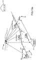
- NeTBUGS system 10 is deployed to monitor traffic behavior of individual vehicles 12 on rural roads 14 outside a town 16.
- NeTBUGS system 10 includes a plurality of autonomously-powered sensor nodes 18 in an ordered network in communication with a control station 20 , typically located within a tactical operations center (TOC).
- Each sensor node has a programmable power management mode including standby and operations times corresponding to high and low-density traffic behavior, respectively. These times may be programmed remotely from the control system to configure or reconfigure the system to anticipated local traffic behavior.
- a unique aspect of NeTBUGS is that the network and individual nodes are configured to detect anomalous behavior during off-peak or low-density traffic conditions.
- NeTBUGS is directed to detecting illegal or threatening vehicle behavior, not merely macro traffic flow or traffic infractions, it is reasonable to assume that such behavior will occur in locations and at times of low-density traffic e.g. on rural roads in the middle of the night.
- NeTBUGS will be deployed where traffic density during operations is ⁇ 600 vehicles/hour or 10 vehicles per minute and more typically ⁇ 180 vehicles/hour or 3 per minute.
- each sensor node detects the time and direction of travel of a passing vehicle 12 and transmits via a communication link a detection message including a node identifier, the detection time and the direction of travel to adjacent nodes and receives detection messages from adjacent nodes.
- Each sensor node operates in a delay mode in which upon expiration of a specified time increment from the detection time reported by the adj acent node without detecting the passage of the anticipated vehicle the node broadcasts an alert delay message including a node identifier, an alert time of vehicle non-arrival and the direction of travel via the communication link.
- the alert delay message may be re-transmitted by other network nodes and is subsequently received at the control station.
- the specified time increment may represent an expected time increment to detect the passage of the anticipated vehicle plus a delay time increment that provides a threshold for issuing an alert.
- the delay time increment may be a fixed multiplier, certain number (potentially fractional) of standard deviations, a fixed time or correspond to a delay calibrated to a specified nuisance alarm rate. Both the expected and delay time increments may be calibrated at the local sensor nodes or provided by the control station.
- the sensor nodes may also be configured remotely from the control station to enable an alert detection mode which broadcasts the detection messages as alert messages that are received by both the adjacent sensor nodes and the control station and a track mode which if enabled enables the alert detection mode for at least the nodes in the vicinity of any node issuing a alert delay message.
- the network may employ a single wireless communication link 22 for all communications between sensors nodes and between sensors nodes and the control station.
- Sensor nodes may be configured to vary their transmission power for local communication with adjacent nodes and for remote communication with the control station to conserve power.
- alert messages may be relayed from node-to-node until the messages reach the node closest the control station at which point they are transmitted to the control station.
- the network may employ a low-power local wireless communications link 24 between sensor nodes and utilize a high-power communications link 22 to communication from designated relay nodes 30 to the control station.
- the relay nodes may be configured to only receive local message traffic (short-range RF communications) and relay the alert messages to the control station (long-range RF communications).
- the relay node may receive message traffic from the control station and distribute the messages to the sensor nodes.
- the relay node may include some or all of the sense and processing capability of a sensor node. Individual sensor nodes may be able to communicate directly with the relay nodes or the alert messages may be relayed node-to-node until they reach the relay node.
- the control station 20 suitably includes both short range RF communications and long-range RF communications plus a computer configured to receive alert delay messages and, knowing the topology of the ordered network and the geolocation of each sensor node, to facilitate timely dispatch of an asset to investigate the anomalous behavior of the vehicle e.g. the location where the vehicle stopped, or track the vehicle.
- the alert is suitably provided through a computer human interface to an operator, to provide a visual display of the monitored road network, the geolocation of each node with its status, any alert messages that have been received and the tracking of any target vehicles through the network.
- the operator in turn dispatches the asset or places a request to dispatch the asset.
- the system could under certain circumstances be configured to determine the appropriate asset and dispatch that asset automatically.
- the assets may be manned response assets (MRA) such as a HMMWV 26 or unmanned response assets (URA) such as an unmanned aerial vehicle (UAV) 28.
- MRA manned response assets
- UAV unmanned aerial vehicle
- a sensor node in NeTBUGS can alert the control station in less than 1 minute and typically less than 10 seconds from the initial determination of a delayed vehicle by that sensor node. The control station may then dispatch the asset in typically 1-5 minutes. NeTBUGS can thus provide a near-real-time response to the detection of anomalous traffic behavior by individual vehicles.
- NeTBUGS To deploy the NeTBUGS system, the individual nodes and network must be emplaced (steps 50 and 52 ), the nodes and network calibrated (step 54 ) and finally the nodes and network must be operational (step 56 ). Precisely what steps must be performed and in what order to emplace, calibrate and operate NeTBUGS may vary depending on specific node configurations, network configurations and the application to which NeTBUGS is applied.
- the emplacement of nodes in step 50 will includes pre-deployment steps such as charging the node (e.g. charging or installing batteries), verifying the Power On Self Test (POST), performing a built-in self test (BIT) and verifying health and internal operation of each node.
- POST Power On Self Test
- BIT built-in self test
- Each node is tested to verify that it can detect a passing vehicle and determine its direction of travel, verify network communications transmit and receive functionality, verify communications connectivity with other sensors nodes and verify communications connectivity with relay nodes if part of the network.
- a geolocation receiver e.g. a GPS receiver
- they are tested to verify operability and to transmit the position of each node.
- a second trailing deployment vehicle deploys a replacement.
- node emplacement verifies that each node can perform its vehicle detection functions, communicate with adjacent nodes and communicate with the control station.
- the emplacement of the network in step 52 includes such steps as installing the computer for the control station, installing RF equipment linking the control station to network of NeTBUGS sensor nodes, running a self test for the control station, verifying the connectivity between the control station and entity(ies) used to request surveillance by manned and unmanned response assets, verifying proper message content and reception between control station and entity(ies) used to request surveillance, verifying connectivity between control station and each node in the network, exercising a self-test in each node to determine the health and projected battery lifetime of each node, logging the geolocation of each node, assigning sequence node identifier numbers to nodes and propagating them throughout the ordered network, verifying communication between adjacent nodes in the ordered network, performing testing to determine which nodes can be missing while retaining a functional network and setting and propagating a network clock time and date.
- the calibration of individual nodes and the network in step 54 may address calibration of the nodes to detect passing vehicles with a high likelihood of detection and a low false alarm rate, determining transmit power levels for local communication among adjacent nodes and for remote communication with the control station, determining the standby and operation times for power management mode, and the collection of traffic statistics to determine the specified time increments for delay reporting.
- the control station may command each node to collect statistics for a sample period on vehicles passing (time and direction of passing), request, receive and process the statistics from each node to determine traffic-flow parameters vs. location and time of day (and perhaps day of week, holiday, etc in addition), determine the likely periods of useful sensor effectiveness and propagate active/standby times to all nodes.
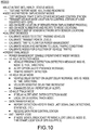
- NeTBUGS has various operational modes that may be remotely enabled and exercised in step 56.
- NeTBUGS enables a local Detection Mode in which the nodes detect passing vehicles and communicate a detection message to the adj acent nodes and a Delay Mode in which nodes upon receipt of such a detection message wait a specified time increment for the anticipated vehicle passing and if the vehicle is not detected communicate an alert delay message to the control system.
- NeTBUGS may also enable more sophisticated versions of the Detection and Delay Modes, a Track Mode, an Anti-Tamper Mode and misc BIT, Health and Status modes.
- NeTBUGS may aggregate statistics on a specific vehicle as it travels through the network (e.g. average velocity) to adjust the expected time increments. In an embodiment, these modes may be enabled/disabled and their parameters set remotely by communication of a control message from the control station to the individual nodes.
- NeTBUGS nodes are autonomously-powered (e.g. batteries, solar power, etc.) and suitably camouflaged for the local environment (e.g. size, shape, color, texture, etc.). It is also preferred that the nodes can be deployed by "throwing" them, manually or via a sensor deployment device, from the back of a moving vehicle.
- the sensor node and the one or more sensors within the node are preferably configured to provide a certain degree of freedom to how the nodes land.
- a traditional node emplacement that involves manually connecting the node to an electrical power grid and carefully aligning the sensor (e.g. camera or radar) or running a pneumatic line across the road would expose both the personnel and the nodes to a threat and also limit deployment options.
- HMMWV HMMWV 62 down a road 64 and "throw" sensor nodes 66 out of the HMMWV to positions along the side the road.
- the sensor nodes may be thrown by hand or by a sensor deployment device (SDD) 68.
- SDD sensor deployment device
- An embodiment of an SDD resembles a baseball pitching machine that tosses nodes 66 at approximately uniform spacing and distance from the road.
- the nodes are typically suitably spaced at 500 meters or less.
- the nodes are typically emplaced on the same side of the road to simplify the detection of passing vehicles and the determination of the direction of travel. The ability to detect and precisely locate delayed vehicles improves with node density but the network cost increases.
- the node and the one or more sensors within the node are preferably configured to provide a certain degree of freedom with respect to how the node lands.
- the node is preferably insensitive to its rotational orientation (as it lands) with respect to the monitored section of the road. If the node is required to land with a certain orientation but once it does is insensitive to rotation, we term that a "rotation insensitive" node. If no constraints are placed on the landing orientation of the node the node is said to be "omni-directional".
- an example of an omni-directional node 70 could be a roughly round package, although other shapes may be used, that can sense a passing vehicle in any direction; no constraints are made on the placement orientation of the sensor.
- An example of a rotation insensitive node 72 would be a cylindrical package that can sense a passing vehicle 360 degrees radially in a cone about its long axis. The package is emplaced so the long axis is nominally perpendicular to the ground. This may be achieved, for example, by weighting the bottom of package. In one embodiment, a heavy sand filled back will cause the node to land on its bottom and remain right side up.
- a rotation insensitive node 74 would be a saucer or FrisbeeTM shaped package that can sense a passing vehicle 360 degrees radially in a cone about an axis perpendicular to the center of the Frisbee.
- the saucer-shaped sensor node will land on either its top or bottom surface and may be shaped and/or weighted so that it will land on a preferred surface.
- a Sensor Node 80 is a self-contained unit consisting of storage 82 that stores instructions for executing the emplacement tests, collecting and processing calibration data and for executing the various operational modes and stores data, a central processing unit (CPU) 84 for executing the instructions stored in memory and controlling other node components, a geolocation receiver 86 such as a Global Positioning System (GPS) for providing the geolocation of the node and a clock 88 that is synchronized to the other nodes and control system.
- GPS Global Positioning System
- the integration of GPS in each node ensures a reliable and precise geolocation of the nodes, to improve location accuracy of the reported anomalous behavior. GPS also enables an anti-tamper mode to detect and track movement of the node after emplacement.
- the GPS time code may be used to provide the synchronized clock.
- An initiator/movement switch 90 turns on the node's power source 92 in response to emplacement landing shock, and is also used to alert CPU 84 if the sensor node is moved following its initial emplacement.
- a sensor package 98 includes one or more sets of different types of sensors with each set including one or more sensors of the same type.
- the package may include 8 magnetometers and 8 seismic-acoustic sensors to provide 360 degree coverage for a rotation insensitive node.
- sensors that could be integrated into the deployed sensor nodes. These include magnetometers, acoustic, seismic, infrared, radar, radio frequency, or laser to name a few. Sensors could also be clustered in a node to provide a wider spectrum of vehicle detection with lower false alarm rates and reduced probability of missed detections. Trade-offs of each sensor and sensor combination should be held to determine the best solution given the mission and the constraints of cost, size, weight, power consumption, and operational environment.
- the sensor node is preferably designed to be sufficiently inexpensive that sensor nodes can be abandoned in-place when power is depleted.
- a magnetometer As shown by plot 110 in Figure 5 the combination of a magnetometer with either an acoustic sensor or a seismic sensor yields a low FAR.
- the acoustic and seismic sensors are each examples of a vibration sensor; sensing vibrations produced by the passing vehicle through the air and through the ground, respectively.
- the Sensor Node may have a structural frame 100 that is small in size, does not stand out in the local environment and is rugged enough to withstand being thrown from the deployment vehicle.
- the frame will typically include camouflage 102 (e.g. color, texture, shape etc.) to further blend in with the local environment.
- camouflage 102 e.g. color, texture, shape etc.
- the Sensor Nodes may be deployed in hostile territory they will depend on small size, irregular geographic distribution and camouflage (e.g. resemblance to stones) to prevent detection.
- the node is suitably provided with some type of orientation mechanism 104 to ensure or increase the probability that the node lands and is emplaced with the desired orientation.
- the mechanism 104 in the case of a FrisbeeTM-shaped node is the shape of the structural frame. The FrisbeeTM will almost invariably land on one of its two large faces.
- the more cylindrical node mechanism 104 may be a heavy bean bag that causes the node to land right side up and stay there.
- Another approach would be to include a simple robotic leg-extender that deploys after landing to flip the node to a desired orientation.
- the orientation mechanism 104 may comprise a sensor to measure the orientation at which the node landed and configure or calibrate the node sensor accordingly. For example a gravity sensor or light detector could determine whether a node landed up or down.
- FIG. 6a An embodiment of an omni-directional sensor node 120 is shown in Figure 6a .
- a single acoustic sensor 122 senses the acoustic signal of vehicles passing in either direction.
- the detection sensitivity may not be uniform in all directions. This may be improved by using multiple acoustic sensors whose directional lobes combine in a complementary fashion. Consequently the node may be deployed and emplaced with any rotational orientation.
- the single acoustic sensor 122 can detect a passing vehicle from its acoustic signature and provide a time stamp when the vehicle passes the node (e.g. the point where the acoustic signal reaches a maximum).
- the direction of travel of the passing vehicle cannot be determined (or determined easily with confidence) from the acoustic signature of a single sensor.
- current Sensor Node 6 uses information forwarded in the detection message from adjacent Sensor Node 7 to determine vehicle direction.
- Sensor Node 6 If based on the time stamp and direction provided in the detection message broadcast by Sensor Node 7, Sensor Node 6 expects to detect a passing vehicle within a specific time increment and does in fact detect the anticipated passing vehicle Sensor Node 6 can assume the direction of the passing vehicle is from Sensor Node 7 towards Sensor Node 6. Conversely, for Figure 6c , the direction of a vehicle traveling from Node 5 to Node 6 will be correctly identified. If both Sensor Nodes 7 and 5 generate detection messages at approximately the same time, indicative of two vehicles passing Sensor Node 6 in opposite directions at roughly the same time the problem is solvable but somewhat more ambiguous. In this case Sensor Node 6 calculates which vehicle should reach Node 6 first and assumes that directionality.
- the network should accurately detect and track the two vehicles as they travel through the remainder of the network.
- nodes possessing a single sensor configuration may require additional processing at each node to determine direction, the power and node-cost savings may be cost effective in certain applications.
- the omni-directional nodes in a sensor string may be placed on both sides of the road and switch back-and-forth without complicating the determination of the direction of travel of passing vehicles.
- FIG. 7a through 7d An embodiment of a rotation insensitive sensor node 130 is shown in Figures 7a through 7d .
- eight magnetometers 132 each having 45 degree conical detection lobes 134 are placed to provide 360 degrees of sense capability around a long axis 136 of the node.
- a like set of eight acoustic or seismic sensors could be placed in the node to improve detection and reduce false alarm rate.
- the node can detect passing vehicles 140 on a road 142 in 360 degrees (i.e. it is insensitive to rotation about the axis).
- a weighted bean bag 144 (or spike or weight) is positioned at the bottom of the node to lower the center of gravity beneath the aerodynamic center of the node. When the node is thrown, this causes the node to flip bean bag side down and land right side up to the side of road 142 .
- the sensors are configured so that a passing vehicle (in either direction) is detected sequentially by at least two sensors (to provide direction). Each of these sensors generates an output response 146 that roughly resembles a raised cosine function as the vehicle passes.
- the node determines the direction of the passing vehicle from the temporal sequence in which the individual output responses go high, combined with input from the control station furnished after emplacement which informed the node which side of the road it is on. For example, 8-1-2 indicates a vehicle traveling left-to-right.
- the use of multiple sensors (per set) improves accuracy, target discrimination and tamper resistance.
- each sensor subsystem or element e.g. each magnetometer, acoustic or seismic sensor
- desirable characteristics of each sensor subsystem or element include sufficient sensitivity from its emplaced position to detect target vehicles traveling along the road.
- the sensors in each set have detection patterns (or lobes) that allow a degree of discrimination as to where in the pattern the target vehicle is, and also to guard against the potential for a single fixed-position jammer to defeat the node.
- the sensitivity is sufficient that each target vehicle is detected by at least two adjacent sensor elements of the same type in their detection lobes.
- the sensor elements have a reasonably wide vertical detection aperture as viewed from the side of an emplaced node to tolerate a degree of imperfect right-side-up alignment.
- the sensor elements of each sensor type are connected to the central processing unit in the node in such a way that the processing unit is aware of the order of sensor responses due to a passing target vehicle.
- the central processing unit can use the input from a sensor element of a given sensor type to approximately determine the instantaneous radial position of the target vehicle in a sensor lobe.
- the processing unit receives information from the Control Station that enables the processing unit to associate the order of detection by the sensor elements of each type with the target vehicle's direction of travel.
- the processing unit in each NeTBUGS node making use of information furnished by the Control System, must "learn” which sensor elements are sensitive to passing target vehicles and accommodate a range of responses due to differences in vehicle characteristics and differences in range (due primarily to direction of travel producing a range offset).
- the processing unit in each node using output levels from each sensor element, must “learn” to disregard the outputs from sensor elements not impinged on by target-vehicle traffic.
- Sensor elements 3 through 7 in the illustrated example Figure 7d there may be anti-tamper or other reasons for retaining the inputs from otherwise-unused sensor elements.
- the processing unit in each node may also need to periodically calibrate out background signals and/or remove sensor-element biases which would otherwise build up and decrease the sensitivity.
- NeTBUGS network 149 A portion of a NeTBUGS network 149 and the message traffic to and from Sensor Nodes 150 , Relay nodes 152 and Control Station 154 is depicted in Figures 8 and 9 .
- the modes supported by NeTBUGS and the remote command and control of the nodes to execute these modes are depicted in Figures 10 and 11 .
- Relay node 152 simply relays message traffic between the Sensor Nodes 150 and the Control Station 154.
- the Relay node 152 is not in this embodiment provisioned with sense capability.
- all message traffic from Control Station 154 passes through Relay node 152 for distribution to Sensor Nodes 150.
- the Sensor Nodes 150 would be configured to receive message traffic directly from the Control Station.
- the Sensor Nodes 150 could be communicating with multiple Relay nodes 152 which in turn are communicating with Control Station 154.
- Sensor Node 150 receives as inputs message traffic from other Sensor Nodes 150 and Relay nodes 152 and the signatures of passing vehicles 155 and transmits message traffic including detection and alert messages and other messages to adjacent Sensor Nodes 150 and Relay nodes 152.
- Message traffic may need to transit multiple Sensor Nodes 150 before reaching Relay node 152.
- Relay node 152 receives message traffic including alert messages from Sensor Nodes 150 and transmits that message traffic to the Control Station 154 and receives message traffic from the Control Station 154 and transmits the message traffic to the Sensor Nodes 150.
- Each of the network components performs various tasks and generates message traffic in response to those various tasks passed through the network.
- Sensor Nodes 150 perform BIT, health and status check periodically and generate message traffic that is passed to the Control Station.
- the Sensor Nodes, Relay nodes and Control Station will also execute different tests of communication and message traffic to ensure communications are functional and transfer data such as Sensor Node geolocations, operational status etc. up to the Control Station and node identifiers, network topology, node location relative to the road, etc, down to the Sensor Nodes.
- the Network and the individual sensor nodes are then calibrated for particular mission objectives and local traffic behavior.
- the Sensor Nodes are typically calibrated to detect passing vehicles with a high likelihood of detection and a low false alarm rate and to determine the direction of the passing vehicles.
- the Sensor Nodes may be calibrated to adjust local transmit power levels for communication among adjacent nodes to ensure the lowest transmit power consistent with robust communication.
- the control station may command each node to collect statistics for a sample period on vehicles passing (time and direction of passing), request, receive and process the statistics from each node to determine traffic-flow parameters vs. location and time of day (and perhaps day of week, holiday, etc in addition), determine the likely periods of useful sensor effectiveness and propagate active/standby times to all nodes.
- the operator of the Control Station may tailor the active/standby times based on local intelligence of the traffic behavior to be monitored.
- each Sensor Node is typically calibrated to local traffic conditions to determine the expected time increment for a vehicle to pass from an adjacent Sensor Node to that node in order to set the specified time intervals at each node for the vehicle delay mode.
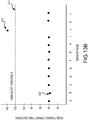
- each sensor node will gather statistics regarding traffic patterns. This data may be used to directly establish each node's expected time increment (measured from the time stamp on a reported detection from an adjacent node).
- a Sensor Node N a number of data points of actual time increments for vehicles to pass from Sensor Node N-1 to Sensor Node N are accumulated. These data points define a distribution 170.
- the expected time increment 172 for a vehicle to travel from Node N-1 to Node N may be set at the expected value of distribution 170.
- the expected time increment for a vehicle travelling in the opposite direction from Node N+1 to Node N may be different due to variations in node spacing, or road conditions that affect typical vehicle speeds.
- the raw data may be transmitted back to the control station and aggregated and possibly combined with external sources of information regarding the mission or local traffic conditions (e.g. posted speed limits) to determine the expected time increment, which are then transmitted back to the respective nodes.
- the mission or local traffic conditions e.g. posted speed limits
- the specified time increment 174 from Node N-1 to Node N is the sum of the expected time increment 172 plus a delay time increment 176.
- This delay time increment can be specified in multiple ways for different reasons.
- One approach is to specify a fixed multiplier of the expected time increment. For example, a multiplier of 1.25 would mean that if the vehicle doesn't arrive within a delay time increment equal to 25% of the expected time increment, the wait to detect the anticipated vehicle has exceeded the threshold and the node issues an alert delay message.
- Another approach is to specify the delay time increment in terms of an x-sigma event, where the x is configurable and may vary from sensor node to sensor node and sigma is the standard deviation of distribution 170.
- the node issues an alert delay message.
- a vehicle stop time that the network will detect and alert on. For example, if the TOC wants to raise an alert anytime a vehicle stops for more than 20 seconds, the delay time increment is set to 20 seconds for each node.
- Yet another approach is to simply allow an operator to make the threshold more or less sensitive to select an acceptable nuisance alarm rate. The TOC will typically have only a certain capability to dispatch assets, hence if the total number of nuisance alarms issued overwhelms the capability to respond the TOC may increase the threshold.
- the node thresholds may be also be configured to alert on vehicles that arrive suspiciously faster than the anticipated increment. In other words, the vehicle is travelling at much higher rate of speed than anticipated. This might be particularly suspicious if the vehicle is travelling at approximately the anticipated speed through the network and than rapidly accelerates. Any of the multiplier, x-sigma or fixed time increments can be used to decrement the expected time interval to set a low alert threshold. The delay-time increments used for high-speed alert and low-speed alert need not be identical.
- the network can be used in one or more of its operational modes listed in Figure 10 to detect individual vehicles throughout the network, identify anomalous behavior (delays or early arrivals) of vehicles, track the identified vehicles throughout the network and generate alerts leading to tasking manned or unmanned response assets to investigate (e.g. track the identified vehicle to its destination and/or investigate the area in which the stoppage was detected).
- these modes can be remotely enabled/disabled and otherwise controlled remotely from the control station. This provides the Control Station operator flexibility to adapt the network as mission parameters or local traffic behavior change.
- the power management mode controls when the Sensor Node is operational and when it is in power-conserving standby mode.
- a unique aspect of NeTBUGS is that the operational times correspond to low-density traffic behavior. Limiting the use of NeTBUGS to low-density traffic is a key enabler. Unambiguously detecting passing vehicles, determining whether a particular one has exceeded a delay threshold and tracking that vehicle through the network would exceed the detection and processing capabilities of the system if applied to high-density traffic. Fortunately the mission of NeTBUGS to monitor illegal or threatening behavior is well suited to its capability. Such activity is not typically conducted during peak traffic conditions. The targeted behavior is more likely to occur on rural roads during the middle of the night when traffic is very low.
- the determination of the operational and standby times may be determined solely based on traffic flow statistics gathered by the network so that the nodes are active only during sufficiently low-density periods. Typically, all of the nodes would have the same operational and standby periods. However, if the network is very large the times may vary. More typically, the statistics are forwarded to the control station, which considers both the traffic flow statistics as well as operational knowledge of the mission and the local environment to set the operational and standby times that are then broadcast back to the sensor nodes.
- Each of the sensor nodes in the network is enabled to detect the passing of vehicles and upon such detection to transmit a detection message.
- the detection message includes a message identifier, a node identifier, a time stamp and a direction of travel of the passing vehicle.
- the detection message is transmitted so that at least the adjacent sensor node in the direction of travel receives the message.
- An alert option may be enabled in which the detection message is identified as an alert.
- the detection message is not only transmitted to the adjacent sensor node to initiate execution of delay mode by that node but is also passed to the control station.
- the TOC may want to know when any vehicle enters the network and passes a node; this capability can also be used to report continuously on all vehicles in the network.
- this alert detection mode can be used to track a vehicle that has been identified as potentially suspicious (e.g. a delay in travelling between two consecutive nodes in the network).
- the alert may be set to only trigger if a node detects a certain density of vehicles (e.g.
- X vehicles detected in Y minutes as such a density of traffic during what is expected to be a period of low-density traffic may be an indicator of illegal or threatening behavior.
- the alert option and the density variant may be remotely enabled/disabled via the control station.
- Each of the sensor nodes in the network are enabled to monitor individually detected vehicles for delays that raise a suspicion of illegal or threatening behavior and upon detection of such a delay to transmit an alert delay message that is passed to the control station for analysis and dispatch of an asset to investigate the suspicious behavior.
- the alert delay message includes a message identifier, a node identifier, a time stamp and a direction of travel of the anticipated but not detected vehicle.
- Control station 154 receives message traffic from Relay nodes 152 and the TOC 156 via computer or the human computer interface such as mission relevant data, external sources of information on local traffic behavior, detection sensitivity etc and transmits message traffic back to the Relay nodes 154 and the TOC 156.
- the Control Station will pass on location and time of possible illegal or threatening vehicle behavior derived by the Control Station from the alert delay messages and other data to the TOC, leading to the deployment of manned response assets (MRA) 158 and/or unmanned response assets (URA) 160 .
- MRA manned response assets
- UAA unmanned response assets
- the TOC provides cueing to the URA such as an unmanned aerial vehicle (UAV) to investigate the area where the anomalous behavior was detected and return imagery of the target vehicle or the area in which the vehicle stopped.
- UAV unmanned aerial vehicle
- the TOC staff analyzes the imagery to determine the appropriate follow-up action.
- the TOC may also task the MRA to track and possibly intercept the target vehicle or to investigate the area of stoppage.
- control station may enable each sensor node to collect and analyze traffic statistics to determine the expected and/or delay time increments. Alternately, the control station may transmit these parameters to each of the sensor nodes. These parameters may be determined in whole or in part by statistics provided by the individual sensor nodes.
- the settings are heavily influenced by the environment in which the NeTBUGS system is deployed. Depending upon the number of available assets to follow up with the detection events, the tolerance for NAR and FAR will vary. Based on these variables, a configurable threshold value is a necessary and useful feature of the NeTBUGS system.
- An approach to both improve detection rate and reduce nuisance alarm rate is to pass forward the velocity history of a target vehicle from the previous N nodes and adapt the specified time increment (threshold) based on this history. More particularly, the velocity history can be used to refine or replace the expected time increment portion of the threshold. In the case of an abnormally slow vehicle the specified time increment would be increased and potentially avoid a nuisance alarm. Conversely, in the case of an abnormally fast vehicle the specified time increment would be reduced and potentially detect a suspicious stop by such a vehicle. This mode may be enabled or disabled via the control station.
- An enhanced delay mode may be enabled for sensor node N+1 to continue to issue the alert message periodically until it detects the target vehicle previously reported by sensor node N, or times out after a specified time period.
- the additional alert message may reinforce or retract the original alert, provide additional information to pass situational awareness to the network or response asset to track the vehicle, or may be used to recalibrate the nodes/network.
- the approximate stop time may be estimated. This may either heighten or reduce interest in the target vehicle.
- these alerts tell the network and the TOC if, when and where the target vehicle starts moving again.
- Some or all of the sensor nodes may be enabled to execute a track mode. If track mode is enabled, when a sensor node reports an alert delay message, suspicious vehicle delay at node N, the vehicle detection alert option is enabled. The effect is that as the target vehicle reappears in the network, each sensor node will report an alert vehicle presence detection message that is passed to the control station. This allows the control station and TOC to "track" the vehicle as it travels through the network. This information may be useful to bridge the period between the issuance of the alert delay message and the ability of URA or MRA to be dispatched and acquire track continuity on the target vehicle. Track may be enabled either "locally” in which only the vehicle of interest is tracked within the network or “universally” in which all vehicles detected anywhere within the network are tracked. Track mode and the local/universal options may be remotely enabled/disabled from the control station.
- the sensor nodes may be programmed to periodically or as needed or when remotely enabled, transfer data to the control station. For example, a log of the detections made by each node, traffic statistics gathered, BIT, health, status etc.
- the nodes may also be enabled to receive data from the control station such as network reconfiguration to bypass failed, end-of-battery-life or missing nodes.
- the network is preferably deployed and configured so that no one sensor node is a single point of failure for the entire network.
- a sensor node In the event that a sensor node is moved after deployment, it immediately transmits a message indicating potential tampering. This message tells adjacent nodes and the control station that the node is compromised and should be removed from the network, and replaced if feasible.
- the node is suitably configured to shutdown the sensing functions and use all of its remaining available power to issue periodic anti-tamper alert messages.
- This message includes a message identifier, a node identifier, a time stamp and the geolocation of the node if available.
- the node is provisioned with a sensor (the Initiator/Movement switch 90 in Figure 4 ) that can simply determine that the node has been moved after emplacement.
- the node is also provisioned with a geolocation receiver that can accurately determine the last known position of the node before it was compromised and periodically broadcast the position of the node as it is moved.
- the TOC may dispatch an asset to track and potentially recover the node.
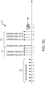
- FIG. 13a An exemplary NetBUGS system 200 deployed for border enforcement, the detected time increments 202 through the network and the message traffic 204 for detecting, alerting and tracking a target vehicle 206 is illustrated in Figures 13a through 13c .
- the U.S. Customs and Border Patrol deploys the NeTBUGS border security system on a network of 100 miles (200 Sensor Nodes 214 at 2 per mile density) of rural roads within 10 miles of the U.S.-Mexico border in an area known for heavy smuggling activity.
- the network is enabled in detection mode to issue local detection messages 208 to neighboring nodes, in delay mode to issue alert delay messages 210 to a control station 211 if a specified time increment following detection by an adjacent node, in enhanced delay mode to periodically reissue the alert delay message 210 with an updated time stamp until the vehicle is reacquired by the network and in local track mode to enable the detection mode alert option to issue alert track messages 212 that are passed to the control station.
- Calibration of the network determined that the average speed of vehicle traffic is 45 mph which corresponds to a 40 sec expected time interval between nodes.
- the delay time increment is set to 80 seconds.
- the specified time increment (“high alert threshold”) 213 is 120 seconds. This threshold will prevent nuisance alarms on even very slow-moving vehicles of down to only 15mph while detecting vehicle stops that exceed 80 seconds (assuming the vehicle is otherwise travelling at 45 mph).
- the system generates an alert.
- a vehicle had been traveling at 45mph and passing hidden sensor nodes 214 (A, B, C, D, ..) roughly every 40sec generating detection messages 208 until the vehicle made a rapid 90sec. stop to pick up 3 border crossers at a pre-arranged rendezvous point between sensor nodes I and J.
- the next sensor node J recorded a 130 second delay 215 , which exceeded its 120 sec. threshold.
- Sensor node J issues an alert delay message 210 and repeats the message until the vehicle is reacquired by sensor node J at which point it issues an alert track message.
- the alert messages may be relayed via relay nodes via a remote comm. link 217 denoted by a communications satellite to the control station.
- the vehicle returns to traveling at 45 mph but the alert has caused the subsequent sensor nodes in the network to track the now acquired vehicle.
- sensor nodes K, L, M, ... detect the passing vehicle on its way to a safe house 216 they each issue an alert track message 212 including the geolocation of the node and a time stamp.
- the initial alert delay message issued by sensor node J is received at the control station 211 , which alerts an operator.
- the computer may cause an icon to flash at sensor node J on a displayed map of the sensor network with the type of alert, node identifier, time stamp, geolocation and direction of travel.
- the computer may update the display to track the vehicle through the map.
- the operator may dispatch a MRA such as a HMMWV 218 to acquire and track the vehicle or a URA such as a UAV 220 to track the vehicle.
Landscapes
- Physics & Mathematics (AREA)
- General Physics & Mathematics (AREA)
- Chemical & Material Sciences (AREA)
- Analytical Chemistry (AREA)
- Traffic Control Systems (AREA)
- Alarm Systems (AREA)
Claims (15)
- Netzwerk aus unbeaufsichtigten Bodensensoren zur Überwachung des Verkehrsverhaltens, umfassend:mehrere autonom mit Leistung versorgte Sensorknoten (18) in einem geordneten Netzwerk, wobei jeder Sensorknoten einen programmierbaren Leistungsverwaltungsmodus einschließlich Standbyund Betriebszeiten entsprechend einem Verkehrsverhalten mit hoher bzw. niedriger Dichte aufweist, wobei jeder Sensorknoten während des Betriebs dazu ausgelegt ist, die Fahrzeit und -richtung eines vorbeifahrenden Fahrzeugs (12) zu detektieren und eine Detektionsnachricht einschließlich einer Knotenkennung, der Detektionszeit und der Richtung der Fahrzeugfahrt über eine Kommunikationsverbindung zu übertragen und Detektionsnachrichten von benachbarten Knoten zu empfangen, wobei jeder Sensorknoten dazu ausgelegt ist, in einem Verzögerungsmodus zu arbeiten, in dem nach dem Verstreichen eines spezifizierten Zeitinkrements von der Detektionszeit, die durch den benachbarten Knoten gemeldet wird, ohne das Vorbeifahren des erwarteten Fahrzeugs zu detektieren, eine Verzögerungswarnnachricht einschließlich einer Knotenkennung, einer Warnzeit der Nichtankunft des Fahrzeugs und der Fahrtrichtung über die Kommunikationsverbindung überträgt, undeine Kontrollstation (20) einschließlich eines Computers, der dazu ausgelegt ist, Verzögerungswarnnachrichten zu empfangen und, unter Kenntnis der Topologie des geordneten Netzwerks und des Geostandorts jedes Sensorknotens, eine rechtzeitige Versendung einer Anlage zu ermöglichen, um das anormale Verhalten des Fahrzeugs untersuchen.
- Netzwerk nach Anspruch 1, wobei das Netzwerk von Sensorknoten kalibriert ist, um vorbeifahrende Fahrzeuge mit einer hohen Detektionswahrscheinlichkeit und einer geringen Falschalarmrate zu detektieren, Sendeleistungspegel für eine lokale Kommunikation unter benachbarten Knoten und für eine Fernkommunikation mit der Kontrollstation zu bestimmen, die Standby- und Betriebszeiten für den Leistungsverwaltungsmodus zu bestimmen, und die Sammlung von Verkehrsstatistiken, um die spezifizierten Zeitinkremente für die Verzögerungsberichterstattung zu bestimmen.
- Netzwerk nach Anspruch 1, ferner umfassend:
mindestens einen autonom mit Leistung versorgten Weiterleitungsknoten, der dazu ausgelegt ist, Verzögerungswarnnachrichten von Sensorknoten über eine lokale Kommunikationsverbindung zu empfangen und die Verzögerungswarnnachrichten über eine Fernkommunikationsverbindung zu der Kontrollstation wieder zu übertragen. - Netzwerk nach Anspruch 1, wobei jeder Sensorknoten der mehreren Sensorknoten Folgendes umfasst:mindestens einen Sensor, der dazu ausgelegt ist, vorbeifahrende Fahrzeuge mit mindestens einem Freiheitsgrad der Drehausrichtung zu erfassen; und optionalmindestens einem beschränkten Freiheitsgrad der Drehausrichtung, wobei der Sensorknoten ferner Mittel zum Orientieren des Knotens umfasst, um den mindestens einen beschränkten Freiheitsgrad zu erfüllen.
- Netzwerk nach Anspruch 1, wobei die Kontrollstation Steuernachrichten zu dem Netzwerk von Sensorknoten überträgt, wobei die Steuernachrichten die Zeiten für den Leistungsverwaltungsmodus der Sensorknoten beinhalten.
- Netzwerk nach Anspruch 1, wobei das spezifizierte Zeitinkrement ein erwartetes Zeitinkrement plus ein Verzögerungszeitinkrement ist und wobei das Netzwerk von Sensorknoten einen Kalibrationsmodus aufweist, in dem die Knoten Statistiken über die Zeitinkremente von Fahrzeugen sammeln, die an benachbarten Knoten in dem Netzwerk vorbeifahren, um die erwarteten Zeitinkremente für jeden Sensorknoten zu bestimmen.
- Netzwerk nach Anspruch 6, wobei das Verzögerungszeitinkrement eines der Folgenden ist:
ein fester Multiplikator des erwarteten Zeitinkrements, eine feste und möglicherweise fraktionale Zahl von Standardabweichungen über das erwartete Zeitinkrement hinaus, eine Schwellenfahrzeugstoppzeit oder eine Verzögerung, die zu einer spezifizierten Fehlalarmrate kalibriert ist, und wobei die Kontrollstation Steuernachrichten zu dem Netzwerk von Sensorknoten überträgt, wobei die Steuernachrichten das Verzögerungszeitinkrement beinhalten. - Netzwerk nach Anspruch 1, wobei die Detektionsnachricht einen Verlauf von tatsächlichen Zeitinkrementen für das vorbeifahrende Fahrzeug beinhaltet, wobei der Sensorknoten die spezifizierten Zeitinkremente basierend auf dem Verlauf modifiziert, um die Verzögerungswarnnachricht für dieses vorbeifahrende Fahrzeug auszulösen.
- Netzwerk nach Anspruch 1, wobei jeder Sensorknoten der mehreren Sensorknoten periodisch die Verzögerungswarnnachricht überträgt, bis der Knoten entweder das vorbeifahrende Fahrzeug detektiert oder eine Zeitbegrenzung erreicht.
- Netzwerk nach Anspruch 1, wobei jeder Sensorknoten der mehreren Sensorknoten einen Detektionsmodus aufweist, in dem die Detektionsnachricht als eine Detektionswarnnachricht übertragen wird, die durch die Kontrollstation empfangen wird.
- Netzwerk nach Anspruch 10, wobei jeder Sensorknoten der mehreren Sensorknoten einen Verfolgungsmodus aufweist, in dem, falls ein Sensorknoten eine Verzögerungswarnnachricht überträgt, zumindest die Sensorknoten in der Nähe dieses Sensorknotens den Detektionsmodus aktivieren und Verfolgungswarnnachrichten bei der Detektion des Fahrzeugs erzeugen.
- Netzwerk nach Anspruch 1, wobei jeder Sensorknoten der mehreren Sensorknoten mehrere Sensoren zum Detektieren von vorbeifahrenden Fahrzeugen bei unterschiedlichen Orientierungen zu dem Knoten beinhaltet, wobei der Knoten dazu ausgelegt ist, die Richtung des vorbeifahrenden Fahrzeugs aus den Detektionsantworten der mehreren Sensoren und der Position des Sensorknotens in der Netzwerktopologie zu bestimmen.
- Netzwerk nach Anspruch 1, wobei jeder Sensorknoten der mehreren Sensorknoten dazu ausgelegt ist, die Richtung des vorbeifahrenden Fahrzeugs aus der geordneten Netzwerktopologie und der von einem benachbarten Knoten empfangenen Detektionsnachricht zu bestimmen.
- Netzwerk nach Anspruch 1, wobei die Kontrollstation eine sequenzielle Knotenkennung zu den Sensorknoten überträgt, um das geordnete Netzwerk zu definieren.
- Netzwerk nach Anspruch 1, wobei jeder Sensorknoten der mehreren Sensorknoten einen Geostandort-Empfänger zum Messen des Geostandorts des Knotens aufweist, wobei jeder Knoten seinen Geostandort und Betriebsstatus überträgt und eine Knotenidentifikationsnummer empfängt, wobei jeder Sensorknoten der mehreren Sensorknoten entfernt programmierbar ist, um in den Folgenden zu arbeiten:einem Detektionswarnmodus, in dem die Detektionsnachrichten als Detektionswarnnachrichten übertragen werden; undeinem Verfolgungsmodus, in dem nach der Übertragung einer Verzögerungswarnnachricht zumindest die Sensorknoten in der Nähe dieses Sensorknotens den Detektionswarnmodus aktivieren; undwobei die Kontrollstation ferner dazu ausgelegt ist, den Geostandort und Betriebsstatus dieses Sensorknotens zu empfangen und die Knotenidentifikationsnummern zu übertragen und Detektionswarnnachrichten zu empfangen.
Applications Claiming Priority (2)
| Application Number | Priority Date | Filing Date | Title |
|---|---|---|---|
| US12/547,532 US8368559B2 (en) | 2009-08-26 | 2009-08-26 | Network of traffic behavior-monitoring unattended ground sensors (NeTBUGS) |
| PCT/US2010/032786 WO2011025563A1 (en) | 2009-08-26 | 2010-04-28 | Network of traffic behavior-monitoring unattended ground sensors (netbugs) |
Publications (2)
| Publication Number | Publication Date |
|---|---|
| EP2471053A1 EP2471053A1 (de) | 2012-07-04 |
| EP2471053B1 true EP2471053B1 (de) | 2020-03-11 |
Family
ID=42320692
Family Applications (1)
| Application Number | Title | Priority Date | Filing Date |
|---|---|---|---|
| EP10719161.1A Active EP2471053B1 (de) | 2009-08-26 | 2010-04-28 | Netzwerk aus unbeaufsichtigten bodensensoren zur überwachung des verkehrsverhaltens (netbugs) |
Country Status (3)
| Country | Link |
|---|---|
| US (1) | US8368559B2 (de) |
| EP (1) | EP2471053B1 (de) |
| WO (1) | WO2011025563A1 (de) |
Families Citing this family (44)
| Publication number | Priority date | Publication date | Assignee | Title |
|---|---|---|---|---|
| US20090185036A1 (en) * | 2006-05-18 | 2009-07-23 | Julian Bowron | Remote in-ground retractable communication system |
| JP5150341B2 (ja) * | 2008-04-10 | 2013-02-20 | 株式会社東芝 | データ作成装置及び方法 |
| CN102356327B (zh) * | 2009-08-20 | 2015-12-09 | 普渡研究基金会 | 用于事件驱动的无线传感器网络的预测性负载循环适配方案 |
| CN102959599B (zh) | 2009-12-22 | 2015-07-15 | 莱达科技股份有限公司 | 用于交通检测的主动3d监控系统 |
| US8138968B1 (en) * | 2010-01-26 | 2012-03-20 | Camgian Microsystems Corp. | Unattended ground sensor system and methods |
| US8908159B2 (en) | 2011-05-11 | 2014-12-09 | Leddartech Inc. | Multiple-field-of-view scannerless optical rangefinder in high ambient background light |
| CA2839194C (en) | 2011-06-17 | 2017-04-18 | Leddartech Inc. | System and method for traffic side detection and characterization |
| US20150324597A1 (en) * | 2011-08-05 | 2015-11-12 | Kpit Technologies Ltd. | A system for protection of embedded software codes |
| US8706458B2 (en) | 2011-10-05 | 2014-04-22 | International Business Machines Corporation | Traffic sensor management |
| ITTO20120184A1 (it) * | 2012-03-01 | 2013-09-02 | Salvatore Volpe | Dispositivo di gestione di code e di incroci in ambienti pedonali e simili. |
| CA2865733C (en) | 2012-03-02 | 2023-09-26 | Leddartech Inc. | System and method for multipurpose traffic detection and characterization |
| JP6172289B2 (ja) * | 2013-10-31 | 2017-08-02 | 日本電気株式会社 | 無線通信システム、無線通信方法、基地制御局及び中継装置 |
| US10057749B1 (en) * | 2013-11-20 | 2018-08-21 | Sprint Spectrum L.P. | Method and system of determining an actual distribution area for an alert |
| US9894158B2 (en) * | 2014-05-19 | 2018-02-13 | EpiSys Science, Inc. | Method and apparatus for control of multiple autonomous mobile nodes based on dynamic situational awareness data |
| CA2960123C (en) | 2014-09-09 | 2021-04-13 | Leddartech Inc. | Discretization of detection zone |
| CN104821084B (zh) * | 2014-09-20 | 2017-01-18 | 罗普特(厦门)科技集团有限公司 | 基于无人机测量的路段交通指数估算系统 |
| CN104240508B (zh) * | 2014-09-20 | 2016-05-04 | 青岛橡胶谷知识产权有限公司 | 用于路段拥堵报警的无人机检测系统 |
| CN107409051B (zh) | 2015-03-31 | 2021-02-26 | 深圳市大疆创新科技有限公司 | 用于生成飞行管制的认证系统和方法 |
| JP6459014B2 (ja) | 2015-03-31 | 2019-01-30 | エスゼット ディージェイアイ テクノロジー カンパニー リミテッドSz Dji Technology Co.,Ltd | ジオフェンシング装置 |
| WO2016209225A1 (en) * | 2015-06-24 | 2016-12-29 | Hewlett Packard Enterprise Development Lp | Control aerial movement of drone based on line-of-sight of humans using devices |
| US10976187B2 (en) | 2015-09-22 | 2021-04-13 | Venti, Llc | Disaster response system and method |
| RU2605507C1 (ru) * | 2015-09-29 | 2016-12-20 | Федеральное государственное казенное образовательное учреждение высшего профессионального образования "Калининградский пограничный институт Федеральной службы безопасности Российской Федерации" | Способ сигнализационного прикрытия локального участка местности с дорогой |
| US10210753B2 (en) | 2015-11-01 | 2019-02-19 | Eberle Design, Inc. | Traffic monitor and method |
| GB201521116D0 (en) * | 2015-11-30 | 2016-01-13 | Optasense Holdings Ltd | Tracking using distributed fibre optic sensing |
| US10156841B2 (en) | 2015-12-31 | 2018-12-18 | General Electric Company | Identity management and device enrollment in a cloud service |
| US10516765B2 (en) * | 2016-03-29 | 2019-12-24 | Resolution Products, Llc | Universal protocol translator |
| US10571908B2 (en) * | 2016-08-15 | 2020-02-25 | Ford Global Technologies, Llc | Autonomous vehicle failure mode management |
| EP3293937A1 (de) * | 2016-09-12 | 2018-03-14 | Vectra Networks, Inc. | Verfahren und system zum erkennen von bösartigen nutzdaten |
| CN106781458B (zh) * | 2016-11-30 | 2019-10-18 | 成都通甲优博科技有限责任公司 | 一种交通事故监控方法及系统 |
| CA2988895A1 (en) | 2016-12-16 | 2018-06-16 | Comcast Cable Communications, Llc | Systems and methods for improved geolocation in a low power wide area network |
| CN110462545A (zh) * | 2017-03-27 | 2019-11-15 | 日本电产新宝株式会社 | 移动体的管理系统、移动体、行驶管理装置以及计算机程序 |
| CN107316459B (zh) * | 2017-07-21 | 2019-07-23 | 武汉依迅北斗空间技术有限公司 | 一种车辆轨迹异常检测方法及系统 |
| US10611381B2 (en) | 2017-10-24 | 2020-04-07 | Ford Global Technologies, Llc | Decentralized minimum risk condition vehicle control |
| US10726645B2 (en) | 2018-02-16 | 2020-07-28 | Ford Global Technologies, Llc | Vehicle diagnostic operation |
| US10991215B2 (en) * | 2018-03-20 | 2021-04-27 | Ideal Industries Lighting Llc | Intelligent signage |
| EP3629226B1 (de) * | 2018-09-26 | 2020-11-25 | Axis AB | Verfahren zur umwandlung von alarmen |
| WO2020070941A1 (ja) * | 2018-10-05 | 2020-04-09 | パナソニック インテレクチュアル プロパティ コーポレーション オブ アメリカ | 情報処理方法、及び、情報処理システム |
| CN109348441A (zh) * | 2018-11-08 | 2019-02-15 | 福建北斗星河通信有限公司 | 一种基于多端交互的稽查管理方法及移动体稽查管理方法 |
| US11967229B1 (en) | 2019-04-19 | 2024-04-23 | Board Of Trustees Of The University Of Alabama, For And On Behalf Of The University Of Alabama In Huntsville | Systems and methods for monitoring vehicular traffic |
| EP3772226B1 (de) * | 2019-07-30 | 2023-01-25 | Volkswagen AG | Verfahren, computerprogramme und vorrichtungen für ein befehlszentrum und fahrzeug |
| CN112333648B (zh) * | 2020-11-11 | 2021-11-02 | 重庆邮电大学 | 一种基于无人机的动态数据收集方法 |
| US12308879B2 (en) * | 2021-04-06 | 2025-05-20 | Lakuruma Systems Ltd. | System and method for bi-directional train to infrastructure wireless optical communication |
| CN113269965B (zh) * | 2021-07-21 | 2021-09-21 | 深圳华晟智慧停车有限公司 | 一种基于互联网的城市道路交通管理监控系统及方法 |
| CN114979315B (zh) * | 2022-03-30 | 2023-12-22 | 江苏杰泽罗通信科技有限公司 | 一种用于车载自组织网络的信道资源共享接入方法 |
Family Cites Families (24)
| Publication number | Priority date | Publication date | Assignee | Title |
|---|---|---|---|---|
| US5416706A (en) * | 1984-04-27 | 1995-05-16 | Hagenbuch; Leroy G. | Apparatus for identifying containers from which refuse is collected and compiling a historical record of the containers |
| US4815757A (en) * | 1986-04-24 | 1989-03-28 | Hamilton Mark L | Rapid development surveillance vehicle and method |
| DE4228539A1 (de) | 1992-08-27 | 1994-03-03 | Deutsche Aerospace | Multisensorsystem zur Erkennung und Identifizierung von Kampfmitteln und Kampfsituationen |
| US6056237A (en) * | 1997-06-25 | 2000-05-02 | Woodland; Richard L. K. | Sonotube compatible unmanned aerial vehicle and system |
| US6121898A (en) * | 1997-10-28 | 2000-09-19 | Moetteli; John B. | Traffic law enforcement system |
| DE19835979B4 (de) * | 1998-08-08 | 2005-01-05 | Daimlerchrysler Ag | Verfahren zur Verkehrszustandsüberwachung und Fahrzeugzuflußsteuerung in einem Straßenverkehrsnetz |
| US6208247B1 (en) * | 1998-08-18 | 2001-03-27 | Rockwell Science Center, Llc | Wireless integrated sensor network using multiple relayed communications |
| US20050041355A1 (en) * | 1999-01-06 | 2005-02-24 | Page J. Dennis | Monitoring and response system |
| WO2001069569A2 (en) * | 2000-03-15 | 2001-09-20 | Raytheon Company | Automatic incident detection |
| US6690292B1 (en) * | 2000-06-06 | 2004-02-10 | Bellsouth Intellectual Property Corporation | Method and system for monitoring vehicular traffic using a wireless communications network |
| US6985090B2 (en) * | 2001-08-29 | 2006-01-10 | Siemens Aktiengesellschaft | Method and arrangement for controlling a system of multiple traffic signals |
| US7336203B2 (en) * | 2003-09-24 | 2008-02-26 | Border Gateways Inc. | Traffic control system and method for use in international border zones |
| US7382281B2 (en) * | 2004-03-01 | 2008-06-03 | Sensys Networks, Inc. | Method and apparatus reporting a vehicular sensor waveform in a wireless vehicular sensor network |
| JP2005267505A (ja) * | 2004-03-22 | 2005-09-29 | Fujitsu Ltd | 交通管理システム |
| US7480560B2 (en) * | 2004-05-14 | 2009-01-20 | Microsoft Corporation | Self-measuring automotive traffic |
| US20070236343A1 (en) * | 2004-09-23 | 2007-10-11 | Becksted Albert M | Surveillance network for unattended ground sensors |
| US7760109B2 (en) * | 2005-03-30 | 2010-07-20 | Memsic, Inc. | Interactive surveillance network and method |
| US8022987B2 (en) * | 2005-06-30 | 2011-09-20 | Sandia Corporation | Information-based self-organization of sensor nodes of a sensor network |
| US7880604B2 (en) * | 2005-09-20 | 2011-02-01 | Selflink, Llc | Self-configuring emergency event alarm system with autonomous output devices |
| DE102005048269B4 (de) * | 2005-10-08 | 2008-01-31 | Diehl Stiftung & Co. Kg | Sensor-Netzwerk sowie Verfahren zur Überwachung eines Geländes |
| US7327262B2 (en) * | 2005-10-12 | 2008-02-05 | Mantic Point Solutions Limited | System and method for electronic article surveillance |
| US7518499B2 (en) * | 2005-10-12 | 2009-04-14 | Agilent Technologies, Inc. | System and method for autonomous interaction among neighboring sensors in a network of sensors |
| US7375652B2 (en) * | 2006-04-25 | 2008-05-20 | At&T Delaware Intellectual Property, Inc. | Systems and devices for assessing fines for traffic disturbances |
| US7633391B2 (en) * | 2006-11-14 | 2009-12-15 | Harris Corporation | Robust tactical unattended ground sensor networking |
-
2009
- 2009-08-26 US US12/547,532 patent/US8368559B2/en active Active
-
2010
- 2010-04-28 WO PCT/US2010/032786 patent/WO2011025563A1/en not_active Ceased
- 2010-04-28 EP EP10719161.1A patent/EP2471053B1/de active Active
Non-Patent Citations (1)
| Title |
|---|
| None * |
Also Published As
| Publication number | Publication date |
|---|---|
| US20110050461A1 (en) | 2011-03-03 |
| EP2471053A1 (de) | 2012-07-04 |
| WO2011025563A1 (en) | 2011-03-03 |
| US8368559B2 (en) | 2013-02-05 |
Similar Documents
| Publication | Publication Date | Title |
|---|---|---|
| EP2471053B1 (de) | Netzwerk aus unbeaufsichtigten bodensensoren zur überwachung des verkehrsverhaltens (netbugs) | |
| US12094324B2 (en) | Edge intelligence powered security solutions and other applications for a smart city | |
| US11782186B2 (en) | Edge intelligence powered security solutions and other applications for a smart city | |
| US10950118B2 (en) | Modular sensing systems and methods | |
| US8779921B1 (en) | Adaptive security network, sensor node and method for detecting anomalous events in a security network | |
| US20130063282A1 (en) | Roadway detection | |
| US8354929B2 (en) | Intruder detector and classifier | |
| US7439876B2 (en) | Microwave detection system and method | |
| CA3163973C (en) | Devices and methods for impact detection and associated data transmission | |
| US20100201561A1 (en) | Goniometric system comprising networks of mini doppler sensors for perimeter surveillance | |
| CN111739349A (zh) | 一种用于石油石化领域的无人机综合管控系统 | |
| US20210156529A1 (en) | Devices and methods for impact detection and associated data transmission | |
| US10089878B2 (en) | Wrong way alert | |
| US20120200431A1 (en) | Traffic monitoring system and method | |
| US12106674B1 (en) | Terrestrial acoustic sensor array | |
| KR101454795B1 (ko) | 무선 메쉬 네트워크와 위치추적을 이용한 산사태 및 낙석 조기 경보 방법 및 시스템 | |
| EP2773977B1 (de) | Eindringungsdetektor | |
| US12057023B1 (en) | Pixellated surveillance of low-altitude aircraft using low-cost networked sensors | |
| CN109444871A (zh) | 行人及动物检测方法、装置、计算机设备及存储介质 | |
| US20220262237A1 (en) | System and method for tracking targets of interest | |
| WO2006013192A1 (en) | Electronic system for defence against fires in forest areas and more generally for monitoring the territory | |
| JP5077197B2 (ja) | 電波監視装置 | |
| Dickinson et al. | An evaluation of microwave vehicle detection at traffic signal controlled intersections | |
| CN121034137A (zh) | 一种非合作类无人机飞行行为的实时监测方法及系统 | |
| Johnson et al. | An unattended ground sensor architecture for persistent border surveillance |
Legal Events
| Date | Code | Title | Description |
|---|---|---|---|
| PUAI | Public reference made under article 153(3) epc to a published international application that has entered the european phase |
Free format text: ORIGINAL CODE: 0009012 |
|
| 17P | Request for examination filed |
Effective date: 20120323 |
|
| AK | Designated contracting states |
Kind code of ref document: A1 Designated state(s): AT BE BG CH CY CZ DE DK EE ES FI FR GB GR HR HU IE IS IT LI LT LU LV MC MK MT NL NO PL PT RO SE SI SK SM TR |
|
| DAX | Request for extension of the european patent (deleted) | ||
| STAA | Information on the status of an ep patent application or granted ep patent |
Free format text: STATUS: EXAMINATION IS IN PROGRESS |
|
| 17Q | First examination report despatched |
Effective date: 20171122 |
|
| GRAP | Despatch of communication of intention to grant a patent |
Free format text: ORIGINAL CODE: EPIDOSNIGR1 |
|
| STAA | Information on the status of an ep patent application or granted ep patent |
Free format text: STATUS: GRANT OF PATENT IS INTENDED |
|
| INTG | Intention to grant announced |
Effective date: 20190722 |
|
| GRAJ | Information related to disapproval of communication of intention to grant by the applicant or resumption of examination proceedings by the epo deleted |
Free format text: ORIGINAL CODE: EPIDOSDIGR1 |
|
| STAA | Information on the status of an ep patent application or granted ep patent |
Free format text: STATUS: EXAMINATION IS IN PROGRESS |
|
| GRAP | Despatch of communication of intention to grant a patent |
Free format text: ORIGINAL CODE: EPIDOSNIGR1 |
|
| STAA | Information on the status of an ep patent application or granted ep patent |
Free format text: STATUS: GRANT OF PATENT IS INTENDED |
|
| INTC | Intention to grant announced (deleted) | ||
| INTG | Intention to grant announced |
Effective date: 20200103 |
|
| GRAS | Grant fee paid |
Free format text: ORIGINAL CODE: EPIDOSNIGR3 |
|
| GRAA | (expected) grant |
Free format text: ORIGINAL CODE: 0009210 |
|
| STAA | Information on the status of an ep patent application or granted ep patent |
Free format text: STATUS: THE PATENT HAS BEEN GRANTED |
|
| AK | Designated contracting states |
Kind code of ref document: B1 Designated state(s): AT BE BG CH CY CZ DE DK EE ES FI FR GB GR HR HU IE IS IT LI LT LU LV MC MK MT NL NO PL PT RO SE SI SK SM TR |
|
| REG | Reference to a national code |
Ref country code: GB Ref legal event code: FG4D |
|
| REG | Reference to a national code |
Ref country code: CH Ref legal event code: EP |
|
| REG | Reference to a national code |
Ref country code: AT Ref legal event code: REF Ref document number: 1244099 Country of ref document: AT Kind code of ref document: T Effective date: 20200315 |
|
| REG | Reference to a national code |
Ref country code: IE Ref legal event code: FG4D |
|
| REG | Reference to a national code |
Ref country code: DE Ref legal event code: R096 Ref document number: 602010063434 Country of ref document: DE |
|
| PG25 | Lapsed in a contracting state [announced via postgrant information from national office to epo] |
Ref country code: NO Free format text: LAPSE BECAUSE OF FAILURE TO SUBMIT A TRANSLATION OF THE DESCRIPTION OR TO PAY THE FEE WITHIN THE PRESCRIBED TIME-LIMIT Effective date: 20200611 Ref country code: FI Free format text: LAPSE BECAUSE OF FAILURE TO SUBMIT A TRANSLATION OF THE DESCRIPTION OR TO PAY THE FEE WITHIN THE PRESCRIBED TIME-LIMIT Effective date: 20200311 |
|
| REG | Reference to a national code |
Ref country code: NL Ref legal event code: MP Effective date: 20200311 |
|
| PG25 | Lapsed in a contracting state [announced via postgrant information from national office to epo] |
Ref country code: GR Free format text: LAPSE BECAUSE OF FAILURE TO SUBMIT A TRANSLATION OF THE DESCRIPTION OR TO PAY THE FEE WITHIN THE PRESCRIBED TIME-LIMIT Effective date: 20200612 Ref country code: HR Free format text: LAPSE BECAUSE OF FAILURE TO SUBMIT A TRANSLATION OF THE DESCRIPTION OR TO PAY THE FEE WITHIN THE PRESCRIBED TIME-LIMIT Effective date: 20200311 Ref country code: BG Free format text: LAPSE BECAUSE OF FAILURE TO SUBMIT A TRANSLATION OF THE DESCRIPTION OR TO PAY THE FEE WITHIN THE PRESCRIBED TIME-LIMIT Effective date: 20200611 Ref country code: LV Free format text: LAPSE BECAUSE OF FAILURE TO SUBMIT A TRANSLATION OF THE DESCRIPTION OR TO PAY THE FEE WITHIN THE PRESCRIBED TIME-LIMIT Effective date: 20200311 Ref country code: SE Free format text: LAPSE BECAUSE OF FAILURE TO SUBMIT A TRANSLATION OF THE DESCRIPTION OR TO PAY THE FEE WITHIN THE PRESCRIBED TIME-LIMIT Effective date: 20200311 |
|
| REG | Reference to a national code |
Ref country code: LT Ref legal event code: MG4D |
|
| PG25 | Lapsed in a contracting state [announced via postgrant information from national office to epo] |
Ref country code: NL Free format text: LAPSE BECAUSE OF FAILURE TO SUBMIT A TRANSLATION OF THE DESCRIPTION OR TO PAY THE FEE WITHIN THE PRESCRIBED TIME-LIMIT Effective date: 20200311 |
|
| PG25 | Lapsed in a contracting state [announced via postgrant information from national office to epo] |
Ref country code: CZ Free format text: LAPSE BECAUSE OF FAILURE TO SUBMIT A TRANSLATION OF THE DESCRIPTION OR TO PAY THE FEE WITHIN THE PRESCRIBED TIME-LIMIT Effective date: 20200311 Ref country code: PT Free format text: LAPSE BECAUSE OF FAILURE TO SUBMIT A TRANSLATION OF THE DESCRIPTION OR TO PAY THE FEE WITHIN THE PRESCRIBED TIME-LIMIT Effective date: 20200805 Ref country code: IS Free format text: LAPSE BECAUSE OF FAILURE TO SUBMIT A TRANSLATION OF THE DESCRIPTION OR TO PAY THE FEE WITHIN THE PRESCRIBED TIME-LIMIT Effective date: 20200711 Ref country code: RO Free format text: LAPSE BECAUSE OF FAILURE TO SUBMIT A TRANSLATION OF THE DESCRIPTION OR TO PAY THE FEE WITHIN THE PRESCRIBED TIME-LIMIT Effective date: 20200311 Ref country code: SK Free format text: LAPSE BECAUSE OF FAILURE TO SUBMIT A TRANSLATION OF THE DESCRIPTION OR TO PAY THE FEE WITHIN THE PRESCRIBED TIME-LIMIT Effective date: 20200311 Ref country code: LT Free format text: LAPSE BECAUSE OF FAILURE TO SUBMIT A TRANSLATION OF THE DESCRIPTION OR TO PAY THE FEE WITHIN THE PRESCRIBED TIME-LIMIT Effective date: 20200311 Ref country code: SM Free format text: LAPSE BECAUSE OF FAILURE TO SUBMIT A TRANSLATION OF THE DESCRIPTION OR TO PAY THE FEE WITHIN THE PRESCRIBED TIME-LIMIT Effective date: 20200311 Ref country code: EE Free format text: LAPSE BECAUSE OF FAILURE TO SUBMIT A TRANSLATION OF THE DESCRIPTION OR TO PAY THE FEE WITHIN THE PRESCRIBED TIME-LIMIT Effective date: 20200311 |
|
| REG | Reference to a national code |
Ref country code: AT Ref legal event code: MK05 Ref document number: 1244099 Country of ref document: AT Kind code of ref document: T Effective date: 20200311 |
|
| REG | Reference to a national code |
Ref country code: CH Ref legal event code: PL |
|
| REG | Reference to a national code |
Ref country code: DE Ref legal event code: R097 Ref document number: 602010063434 Country of ref document: DE |
|
| PG25 | Lapsed in a contracting state [announced via postgrant information from national office to epo] |
Ref country code: MC Free format text: LAPSE BECAUSE OF FAILURE TO SUBMIT A TRANSLATION OF THE DESCRIPTION OR TO PAY THE FEE WITHIN THE PRESCRIBED TIME-LIMIT Effective date: 20200311 |
|
| PLBE | No opposition filed within time limit |
Free format text: ORIGINAL CODE: 0009261 |
|
| STAA | Information on the status of an ep patent application or granted ep patent |
Free format text: STATUS: NO OPPOSITION FILED WITHIN TIME LIMIT |
|
| PG25 | Lapsed in a contracting state [announced via postgrant information from national office to epo] |
Ref country code: AT Free format text: LAPSE BECAUSE OF FAILURE TO SUBMIT A TRANSLATION OF THE DESCRIPTION OR TO PAY THE FEE WITHIN THE PRESCRIBED TIME-LIMIT Effective date: 20200311 Ref country code: LI Free format text: LAPSE BECAUSE OF NON-PAYMENT OF DUE FEES Effective date: 20200430 Ref country code: CH Free format text: LAPSE BECAUSE OF NON-PAYMENT OF DUE FEES Effective date: 20200430 Ref country code: DK Free format text: LAPSE BECAUSE OF FAILURE TO SUBMIT A TRANSLATION OF THE DESCRIPTION OR TO PAY THE FEE WITHIN THE PRESCRIBED TIME-LIMIT Effective date: 20200311 Ref country code: LU Free format text: LAPSE BECAUSE OF NON-PAYMENT OF DUE FEES Effective date: 20200428 Ref country code: IT Free format text: LAPSE BECAUSE OF FAILURE TO SUBMIT A TRANSLATION OF THE DESCRIPTION OR TO PAY THE FEE WITHIN THE PRESCRIBED TIME-LIMIT Effective date: 20200311 Ref country code: ES Free format text: LAPSE BECAUSE OF FAILURE TO SUBMIT A TRANSLATION OF THE DESCRIPTION OR TO PAY THE FEE WITHIN THE PRESCRIBED TIME-LIMIT Effective date: 20200311 |
|
| REG | Reference to a national code |
Ref country code: BE Ref legal event code: MM Effective date: 20200430 |
|
| 26N | No opposition filed |
Effective date: 20201214 |
|
| PG25 | Lapsed in a contracting state [announced via postgrant information from national office to epo] |
Ref country code: PL Free format text: LAPSE BECAUSE OF FAILURE TO SUBMIT A TRANSLATION OF THE DESCRIPTION OR TO PAY THE FEE WITHIN THE PRESCRIBED TIME-LIMIT Effective date: 20200311 Ref country code: SI Free format text: LAPSE BECAUSE OF FAILURE TO SUBMIT A TRANSLATION OF THE DESCRIPTION OR TO PAY THE FEE WITHIN THE PRESCRIBED TIME-LIMIT Effective date: 20200311 Ref country code: BE Free format text: LAPSE BECAUSE OF NON-PAYMENT OF DUE FEES Effective date: 20200430 |
|
| PG25 | Lapsed in a contracting state [announced via postgrant information from national office to epo] |
Ref country code: IE Free format text: LAPSE BECAUSE OF NON-PAYMENT OF DUE FEES Effective date: 20200428 Ref country code: FR Free format text: LAPSE BECAUSE OF NON-PAYMENT OF DUE FEES Effective date: 20200511 |
|
| PG25 | Lapsed in a contracting state [announced via postgrant information from national office to epo] |
Ref country code: TR Free format text: LAPSE BECAUSE OF FAILURE TO SUBMIT A TRANSLATION OF THE DESCRIPTION OR TO PAY THE FEE WITHIN THE PRESCRIBED TIME-LIMIT Effective date: 20200311 Ref country code: MT Free format text: LAPSE BECAUSE OF FAILURE TO SUBMIT A TRANSLATION OF THE DESCRIPTION OR TO PAY THE FEE WITHIN THE PRESCRIBED TIME-LIMIT Effective date: 20200311 Ref country code: CY Free format text: LAPSE BECAUSE OF FAILURE TO SUBMIT A TRANSLATION OF THE DESCRIPTION OR TO PAY THE FEE WITHIN THE PRESCRIBED TIME-LIMIT Effective date: 20200311 |
|
| PG25 | Lapsed in a contracting state [announced via postgrant information from national office to epo] |
Ref country code: MK Free format text: LAPSE BECAUSE OF FAILURE TO SUBMIT A TRANSLATION OF THE DESCRIPTION OR TO PAY THE FEE WITHIN THE PRESCRIBED TIME-LIMIT Effective date: 20200311 |
|
| P01 | Opt-out of the competence of the unified patent court (upc) registered |
Effective date: 20230530 |
|
| PGFP | Annual fee paid to national office [announced via postgrant information from national office to epo] |
Ref country code: DE Payment date: 20250319 Year of fee payment: 16 |
|
| PGFP | Annual fee paid to national office [announced via postgrant information from national office to epo] |
Ref country code: GB Payment date: 20260319 Year of fee payment: 17 |