EP2470825B1 - Lampe d'éclairage général - Google Patents
Lampe d'éclairage général Download PDFInfo
- Publication number
- EP2470825B1 EP2470825B1 EP10741991.3A EP10741991A EP2470825B1 EP 2470825 B1 EP2470825 B1 EP 2470825B1 EP 10741991 A EP10741991 A EP 10741991A EP 2470825 B1 EP2470825 B1 EP 2470825B1
- Authority
- EP
- European Patent Office
- Prior art keywords
- light
- type
- light source
- lamp
- exit opening
- Prior art date
- Legal status (The legal status is an assumption and is not a legal conclusion. Google has not performed a legal analysis and makes no representation as to the accuracy of the status listed.)
- Active
Links
- 238000001816 cooling Methods 0.000 claims description 21
- 230000005855 radiation Effects 0.000 claims description 12
- 238000001228 spectrum Methods 0.000 description 5
- 230000005670 electromagnetic radiation Effects 0.000 description 3
- 230000003287 optical effect Effects 0.000 description 3
- 238000009877 rendering Methods 0.000 description 3
- 230000015572 biosynthetic process Effects 0.000 description 2
- 239000002131 composite material Substances 0.000 description 2
- 230000004907 flux Effects 0.000 description 2
- 239000002184 metal Substances 0.000 description 2
- 229910052751 metal Inorganic materials 0.000 description 2
- 239000000203 mixture Substances 0.000 description 2
- 238000007493 shaping process Methods 0.000 description 2
- 239000002918 waste heat Substances 0.000 description 2
- 229910010293 ceramic material Inorganic materials 0.000 description 1
- 150000001875 compounds Chemical class 0.000 description 1
- 239000011521 glass Substances 0.000 description 1
- 230000017525 heat dissipation Effects 0.000 description 1
- 238000005286 illumination Methods 0.000 description 1
- 238000004519 manufacturing process Methods 0.000 description 1
- 230000007935 neutral effect Effects 0.000 description 1
- 238000002310 reflectometry Methods 0.000 description 1
- 230000006641 stabilisation Effects 0.000 description 1
- 238000011105 stabilization Methods 0.000 description 1
- 238000003466 welding Methods 0.000 description 1
Images


Classifications
-
- F—MECHANICAL ENGINEERING; LIGHTING; HEATING; WEAPONS; BLASTING
- F21—LIGHTING
- F21K—NON-ELECTRIC LIGHT SOURCES USING LUMINESCENCE; LIGHT SOURCES USING ELECTROCHEMILUMINESCENCE; LIGHT SOURCES USING CHARGES OF COMBUSTIBLE MATERIAL; LIGHT SOURCES USING SEMICONDUCTOR DEVICES AS LIGHT-GENERATING ELEMENTS; LIGHT SOURCES NOT OTHERWISE PROVIDED FOR
- F21K9/00—Light sources using semiconductor devices as light-generating elements, e.g. using light-emitting diodes [LED] or lasers
- F21K9/20—Light sources comprising attachment means
- F21K9/23—Retrofit light sources for lighting devices with a single fitting for each light source, e.g. for substitution of incandescent lamps with bayonet or threaded fittings
- F21K9/237—Details of housings or cases, i.e. the parts between the light-generating element and the bases; Arrangement of components within housings or cases
-
- F—MECHANICAL ENGINEERING; LIGHTING; HEATING; WEAPONS; BLASTING
- F21—LIGHTING
- F21S—NON-PORTABLE LIGHTING DEVICES; SYSTEMS THEREOF; VEHICLE LIGHTING DEVICES SPECIALLY ADAPTED FOR VEHICLE EXTERIORS
- F21S6/00—Lighting devices intended to be free-standing
- F21S6/002—Table lamps, e.g. for ambient lighting
-
- F—MECHANICAL ENGINEERING; LIGHTING; HEATING; WEAPONS; BLASTING
- F21—LIGHTING
- F21S—NON-PORTABLE LIGHTING DEVICES; SYSTEMS THEREOF; VEHICLE LIGHTING DEVICES SPECIALLY ADAPTED FOR VEHICLE EXTERIORS
- F21S6/00—Lighting devices intended to be free-standing
- F21S6/004—Lighting devices intended to be free-standing with a lamp housing in direct contact with the floor or ground
-
- F—MECHANICAL ENGINEERING; LIGHTING; HEATING; WEAPONS; BLASTING
- F21—LIGHTING
- F21V—FUNCTIONAL FEATURES OR DETAILS OF LIGHTING DEVICES OR SYSTEMS THEREOF; STRUCTURAL COMBINATIONS OF LIGHTING DEVICES WITH OTHER ARTICLES, NOT OTHERWISE PROVIDED FOR
- F21V21/00—Supporting, suspending, or attaching arrangements for lighting devices; Hand grips
- F21V21/02—Wall, ceiling, or floor bases; Fixing pendants or arms to the bases
-
- F—MECHANICAL ENGINEERING; LIGHTING; HEATING; WEAPONS; BLASTING
- F21—LIGHTING
- F21V—FUNCTIONAL FEATURES OR DETAILS OF LIGHTING DEVICES OR SYSTEMS THEREOF; STRUCTURAL COMBINATIONS OF LIGHTING DEVICES WITH OTHER ARTICLES, NOT OTHERWISE PROVIDED FOR
- F21V21/00—Supporting, suspending, or attaching arrangements for lighting devices; Hand grips
- F21V21/10—Pendants, arms, or standards; Fixing lighting devices to pendants, arms, or standards
- F21V21/108—Arms
-
- F—MECHANICAL ENGINEERING; LIGHTING; HEATING; WEAPONS; BLASTING
- F21—LIGHTING
- F21V—FUNCTIONAL FEATURES OR DETAILS OF LIGHTING DEVICES OR SYSTEMS THEREOF; STRUCTURAL COMBINATIONS OF LIGHTING DEVICES WITH OTHER ARTICLES, NOT OTHERWISE PROVIDED FOR
- F21V29/00—Protecting lighting devices from thermal damage; Cooling or heating arrangements specially adapted for lighting devices or systems
- F21V29/50—Cooling arrangements
- F21V29/70—Cooling arrangements characterised by passive heat-dissipating elements, e.g. heat-sinks
- F21V29/74—Cooling arrangements characterised by passive heat-dissipating elements, e.g. heat-sinks with fins or blades
- F21V29/75—Cooling arrangements characterised by passive heat-dissipating elements, e.g. heat-sinks with fins or blades with fins or blades having different shapes, thicknesses or spacing
-
- F—MECHANICAL ENGINEERING; LIGHTING; HEATING; WEAPONS; BLASTING
- F21—LIGHTING
- F21V—FUNCTIONAL FEATURES OR DETAILS OF LIGHTING DEVICES OR SYSTEMS THEREOF; STRUCTURAL COMBINATIONS OF LIGHTING DEVICES WITH OTHER ARTICLES, NOT OTHERWISE PROVIDED FOR
- F21V29/00—Protecting lighting devices from thermal damage; Cooling or heating arrangements specially adapted for lighting devices or systems
- F21V29/50—Cooling arrangements
- F21V29/70—Cooling arrangements characterised by passive heat-dissipating elements, e.g. heat-sinks
- F21V29/74—Cooling arrangements characterised by passive heat-dissipating elements, e.g. heat-sinks with fins or blades
- F21V29/76—Cooling arrangements characterised by passive heat-dissipating elements, e.g. heat-sinks with fins or blades with essentially identical parallel planar fins or blades, e.g. with comb-like cross-section
- F21V29/767—Cooling arrangements characterised by passive heat-dissipating elements, e.g. heat-sinks with fins or blades with essentially identical parallel planar fins or blades, e.g. with comb-like cross-section the planes containing the fins or blades having directions perpendicular to the light emitting axis
-
- F—MECHANICAL ENGINEERING; LIGHTING; HEATING; WEAPONS; BLASTING
- F21—LIGHTING
- F21S—NON-PORTABLE LIGHTING DEVICES; SYSTEMS THEREOF; VEHICLE LIGHTING DEVICES SPECIALLY ADAPTED FOR VEHICLE EXTERIORS
- F21S8/00—Lighting devices intended for fixed installation
- F21S8/04—Lighting devices intended for fixed installation intended only for mounting on a ceiling or the like overhead structures
-
- F—MECHANICAL ENGINEERING; LIGHTING; HEATING; WEAPONS; BLASTING
- F21—LIGHTING
- F21V—FUNCTIONAL FEATURES OR DETAILS OF LIGHTING DEVICES OR SYSTEMS THEREOF; STRUCTURAL COMBINATIONS OF LIGHTING DEVICES WITH OTHER ARTICLES, NOT OTHERWISE PROVIDED FOR
- F21V29/00—Protecting lighting devices from thermal damage; Cooling or heating arrangements specially adapted for lighting devices or systems
- F21V29/50—Cooling arrangements
- F21V29/502—Cooling arrangements characterised by the adaptation for cooling of specific components
- F21V29/507—Cooling arrangements characterised by the adaptation for cooling of specific components of means for protecting lighting devices from damage, e.g. housings
-
- F—MECHANICAL ENGINEERING; LIGHTING; HEATING; WEAPONS; BLASTING
- F21—LIGHTING
- F21V—FUNCTIONAL FEATURES OR DETAILS OF LIGHTING DEVICES OR SYSTEMS THEREOF; STRUCTURAL COMBINATIONS OF LIGHTING DEVICES WITH OTHER ARTICLES, NOT OTHERWISE PROVIDED FOR
- F21V29/00—Protecting lighting devices from thermal damage; Cooling or heating arrangements specially adapted for lighting devices or systems
- F21V29/50—Cooling arrangements
- F21V29/70—Cooling arrangements characterised by passive heat-dissipating elements, e.g. heat-sinks
- F21V29/74—Cooling arrangements characterised by passive heat-dissipating elements, e.g. heat-sinks with fins or blades
- F21V29/745—Cooling arrangements characterised by passive heat-dissipating elements, e.g. heat-sinks with fins or blades the fins or blades being planar and inclined with respect to the joining surface from which the fins or blades extend
-
- F—MECHANICAL ENGINEERING; LIGHTING; HEATING; WEAPONS; BLASTING
- F21—LIGHTING
- F21W—INDEXING SCHEME ASSOCIATED WITH SUBCLASSES F21K, F21L, F21S and F21V, RELATING TO USES OR APPLICATIONS OF LIGHTING DEVICES OR SYSTEMS
- F21W2131/00—Use or application of lighting devices or systems not provided for in codes F21W2102/00-F21W2121/00
- F21W2131/30—Lighting for domestic or personal use
-
- F—MECHANICAL ENGINEERING; LIGHTING; HEATING; WEAPONS; BLASTING
- F21—LIGHTING
- F21Y—INDEXING SCHEME ASSOCIATED WITH SUBCLASSES F21K, F21L, F21S and F21V, RELATING TO THE FORM OR THE KIND OF THE LIGHT SOURCES OR OF THE COLOUR OF THE LIGHT EMITTED
- F21Y2105/00—Planar light sources
-
- F—MECHANICAL ENGINEERING; LIGHTING; HEATING; WEAPONS; BLASTING
- F21—LIGHTING
- F21Y—INDEXING SCHEME ASSOCIATED WITH SUBCLASSES F21K, F21L, F21S and F21V, RELATING TO THE FORM OR THE KIND OF THE LIGHT SOURCES OR OF THE COLOUR OF THE LIGHT EMITTED
- F21Y2113/00—Combination of light sources
-
- F—MECHANICAL ENGINEERING; LIGHTING; HEATING; WEAPONS; BLASTING
- F21—LIGHTING
- F21Y—INDEXING SCHEME ASSOCIATED WITH SUBCLASSES F21K, F21L, F21S and F21V, RELATING TO THE FORM OR THE KIND OF THE LIGHT SOURCES OR OF THE COLOUR OF THE LIGHT EMITTED
- F21Y2113/00—Combination of light sources
- F21Y2113/10—Combination of light sources of different colours
- F21Y2113/13—Combination of light sources of different colours comprising an assembly of point-like light sources
-
- F—MECHANICAL ENGINEERING; LIGHTING; HEATING; WEAPONS; BLASTING
- F21—LIGHTING
- F21Y—INDEXING SCHEME ASSOCIATED WITH SUBCLASSES F21K, F21L, F21S and F21V, RELATING TO THE FORM OR THE KIND OF THE LIGHT SOURCES OR OF THE COLOUR OF THE LIGHT EMITTED
- F21Y2113/00—Combination of light sources
- F21Y2113/20—Combination of light sources of different form
-
- F—MECHANICAL ENGINEERING; LIGHTING; HEATING; WEAPONS; BLASTING
- F21—LIGHTING
- F21Y—INDEXING SCHEME ASSOCIATED WITH SUBCLASSES F21K, F21L, F21S and F21V, RELATING TO THE FORM OR THE KIND OF THE LIGHT SOURCES OR OF THE COLOUR OF THE LIGHT EMITTED
- F21Y2115/00—Light-generating elements of semiconductor light sources
- F21Y2115/10—Light-emitting diodes [LED]
- F21Y2115/15—Organic light-emitting diodes [OLED]
Definitions
- a lamp is indicated.
- the invention relates to a lamp according to claim 1.
- the lamp is preferably suitable for general lighting.
- the lamp is suitable for room lighting or as a desk lamp.
- the lamp is suitable for ceiling mounting, but can also be used freestanding.
- the lamp is characterized by a high luminous flux of at least 100 lm, preferably at least 500 lm, for example 1000 lm.
- the lamp may be suitable for emitting cold white, neutral white, warm white or even colored light and may have a color rendering index Ra of> 90.
- the color or the color location and / or the color temperature of the light emitted by the lamp can be adjustable.
- the lamp comprises a lamp housing which has a light exit opening.
- the lamp housing is used for example for receiving a drive device for controlling the light sources of the lamp. Further, the lamp housing may serve to receive a portion of the light source of the lamp.
- the lamp housing therefore has a light exit opening from which light generated in the lamp housing can leave the lamp housing.
- the arranged in the lamp housing light source is Covered by the lamp housing, light generated by it can leave the lamp housing only through the light exit opening.
- the lamp comprises a light source of the first type, which is arranged in the lamp housing.
- the light source of the first kind can be For example, be a light source, which comprises one or more light-emitting diode chips, preferably inorganic light-emitting diode chips.
- the light source may consist of at least one unhoused LED chip.
- the light source of the first type may alternatively or additionally comprise a discharge lamp and / or a light bulb and / or an energy-saving lamp.
- the light source of the first type may further comprise at least one optical element such as a reflector or a lens.
- the optical element can serve for beam shaping of the emitted light.
- the light source of the first kind can therefore be a light module.
- the light source of the first kind is arranged in the lamp housing. The light generated by the light source of the first type during operation of the lamp leaves the lamp housing through the light exit opening of the lamp housing.
- the lamp comprises a holder which is fastened to the lamp housing.
- the holder can be formed in one or more parts.
- the holder comprises at least two rods which are mechanically fastened to the lamp housing.
- the holder may be welded, caulked or screwed to the lamp housing.
- the holder preferably extends along a radiation direction of the light emerging from the light exit opening of the lamp housing. That is, the holder is at least in places downstream of the light exit opening in a radiation direction.
- the lamp comprises at least one light source of the second type, which is fastened to the holder.
- the light source of the second kind differs from the light source of the first kind. That is, Preferably, different types of light sources are used for the light sources of the first type and the light sources of the second type.
- the light source of the second type is preferably a flat light source which has a radiation area of at least 1 cm 2 , preferably of at least 4.5 cm 2 , for example of 4.9 cm 2 or 10 cm 2 .
- the radiation of the light of the light source of the second type can also take place from the emission surface in two opposite directions. That is, light may be from a front side and a back side of the emission surface.
- the light source of the second type comprises an organic light-emitting diode.
- the light source of the second kind can for example consist of an organic light-emitting diode.
- the organic light emitting diode is provided, for example, for emitting white light.
- the light source of the second kind emits white light during operation of the lamp at a color temperature between 2500 K and 3000 K, for example at a color temperature of 2800 K.
- the at least one light source of the second type is arranged downstream of the light exit opening of the lamp housing in a radiation direction. From the light exit opening of the lamp housing occurs during operation of the lamp light of the light source of the first kind.
- the light source of the first type is the primary light source of the lamp.
- the direction of the exiting light is the emission direction.
- the light sources of the second kind are the light exit opening downstream in the emission direction.
- the light sources of the second type are arranged downstream of the light exit opening in a main emission direction.
- the main emission direction is that emission direction in which the emitted light has an intensity maximum.
- the main emission direction is perpendicular to an imaginary plane which covers the light exit opening.
- the lamp comprises a lamp housing which has a light exit opening. Furthermore, the lamp comprises a light source of the first type, which is arranged in the lamp housing. The lamp further includes a holder which is attached to the lamp housing. Furthermore, the lamp comprises a light source of the second kind, which is fastened to the holder.
- the light source of the second type comprises an organic light-emitting diode or another light source and is arranged downstream of the light exit opening in a radiation direction.
- the lamp comprises at least two light sources of the second type. Preferably, all light sources of the second type are arranged downstream of the lamp of the light exit opening in a radiation direction, for example in a main emission direction.
- At least one of the at least one light source of the second type is designed to be reflective at least in places.
- This light source of the second kind can be designed to be reflective, for example, on its rear side facing away from the emission side. Furthermore, it is possible that the light source of the second type is designed to be reflective on its emission side.
- this second type of light source can then be a reflective organic light-emitting diode.
- the light source of the second kind indicates their reflectively formed surfaces preferably have a reflectivity of at least 50%, preferably at least 70%, for example 80% for visible light.
- the reflective light source of the second type is illuminated during operation of the light source of the first type emitted by the light exit opening of the lamp housing light. This light strikes the second type of light source and is reflected if it encounters reflective formed areas of the second type of light source.
- the light source of the second kind which is at least locally reflective, not only actively emits light, but also reflects the light emitted by the light source of the first type through the light exit opening of the lamp housing. Since the light source of the first kind is covered by the lamp housing and therefore the light source of the first kind is not visible from the outside, it appears to a viewer as if the light source of the second kind emits more light than is actually the case. In this way, despite the use of relatively faint organic light-emitting diodes, a lamp with high luminous flux can be achieved.
- At least one of the at least one light source of the second type is at least partially radiation-transmissive.
- the second type In the operation of the light source of the first kind radiated light impinges on this light source of the second kind and can irradiate them.
- the radiation-transmissive designed light source the second type can then be a radiation-transmissive organic light-emitting diode.
- the light of the first light source passing through the light source of the second type may mix with the light of the light source of the second kind so that a total of mixed light is radiated. It is also true for irradiated light sources of the second kind that they appear brighter to the external observer than would be the case without being irradiated with the light of the first type of light source.
- the lamp may comprise a mixture of light sources of the second type, wherein a part of the light sources is designed to be reflective and another part of the light sources is radiation-transmissive.
- the lamp it is possible for the lamp to comprise only secondarily formed light sources of a reflective design or only secondarily transparent light sources of radiation-like design.
- the lamp housing has a first cavity in which the light source of the first type is arranged, wherein an inner surface of the first cavity facing the light source of the first type is designed to be reflective.
- Light generated in operation by the light source of the first type is reflected on the inner surface of the cavity.
- the light is at least partially reflected such that it reaches the light exit opening of the lamp housing.
- the inner surface of the cavity which is formed to be reflective, may for this purpose have a shape which assists a reflection in the direction of the light exit opening.
- the inner surface may be formed at least in places in the manner of a composite parabolic concentrator, a composite elliptical concentrator or a compound hyperbolic concentrator.
- the first cavity may be formed at least in places as a truncated pyramid or truncated cone with reflective inner surfaces.
- the reflective inner surface of the cavity can also serve to mix the light generated by the light source of the first kind before the light exit through the light exit opening.
- the light source of the first type may include, for example, light-emitting diode chips of different color, the light of which is mixed in the first cavity to white light.
- An additional diffuser can be omitted in this case.
- the lamp housing comprises a first cavity, which is formed in places in the manner of an ellipsoid, preferably an ellipsoid of revolution.
- “In the manner of an ellipsoid” means that an inner surface of the first cavity follows the shape of an ellipsoid with a deviation of at most 15%, preferably at most 10%. Within the manufacturing tolerance, the inner surface can at least in places follow the course of an ellipsoid.
- “In places” means that the cavity in areas can not be formed as ellipsoid. For example, the Cavity formed in the manner of an ellipsoid, which is cut off in the region of its focal planes along the focal planes.
- the light source of the first type of lamp is preferably arranged in the vicinity of a focal point of the ellipsoid, which is remote from the light exit opening of the lamp housing.
- the ellipsoid may be cut off in the region of the focal point, for example along the focal plane.
- the light source is then preferably arranged such that the focal point lies in a plane in which a light exit opening of the light source is located.
- the light source can thus be arranged in the focal point of the ellipsoid of revolution.
- the light exit opening is preferably arranged in the vicinity of the other focal point of the ellipsoid.
- the cavity in the region of the other focal point is open and has there the light exit opening.
- the other focal point may then lie, for example, in the plane which terminates the light exit opening.
- the inner surfaces of the first cavity are preferably designed to be reflective and reflect the light impinging on them preferably directed and non-diffusive. The reflections on the inner surface of the cavity also causes a mixing of the light. If the cavity is designed as an ellipsoid, preferably as an ellipsoid of revolution, the light exit opening can additionally be selected to be relatively small.
- a maximum diameter of the light exit opening is at most twice as large as the diameter of the light exit opening of the light source. In this way it can be ensured that the light source of the first kind is hardly or not at all visible from outside the lamp housing under most viewing angles. This reinforces the impression that all the light emitted by the lamp is emitted by the light sources of the second kind.
- the light source comprises a plurality of inorganic light-emitting diode chips
- the diameter of the light exit opening of the light source is, for example, the diameter of the sum of the radiation exit areas of the light-emitting diode chips.
- the lamp housing has a second cavity, which is arranged on a side of the first cavity facing away from the light exit opening.
- a drive device for the light sources of the first type and the light sources of the second type can be arranged in the second cavity.
- the drive device can be, for example, a pulse width modulation circuit, via which at least one of the light sources can be dimmed.
- the drive device may further comprise a memory device in which different light functions of the lamp are stored, which can be retrieved by a user from outside the lamp. For example, the lamp can thereby be operated at different color temperatures and / or at different color locations.
- the lamp housing has a base body, which at least in places in the manner of a truncated cone or a Truncated pyramid or a cylinder is formed. If the lamp housing is designed in the manner of a truncated cone or a truncated pyramid, then it preferably tapers in a direction which leads away from the light exit opening of the lamp housing.
- the lamp housing can also be designed in several parts. For example, the lamp housing may have a first region in which it is designed in the manner of a truncated cone, which tapers in the direction away from the light exit opening.
- the lamp housing can then have a second section, in which it is designed, for example, as a cylinder. The second section then adjoins the first section on the side of the first section facing away from the light exit opening.
- the lamp housing has a main body and at least two cooling disks, which are fastened to one another at the base body.
- the cooling disks are mounted in a vertical direction spaced from each other on the base body.
- the cooling disks may be cylindrical, for example.
- the cooling disks preferably surround the main body laterally, for example completely laterally.
- the cooling disks thus increase the outer surface of the lamp housing and lead to an improved heat dissipation of the heat generated by the light source of the first kind during operation.
- the lamp comprises at least five, for example eleven, cooling disks.
- the cooling disks can also be integrally formed with the base body or they are mechanically connected to the body - for example by welding - connected.
- the cooling disks and the base body can be formed with a metal or a ceramic material.
- the outer surface of the lamp housing surrounding the light exit opening is designed to be reflective at least in places. That is, for example, the outer surface of the base body, which laterally surrounds the light exit opening, is designed to be reflective for light generated by the light sources, so that additionally a reflection of light through this outer area takes place in the direction of the light sources of the second type.
- the holder of the lamp which is fastened to the lamp housing, is provided for electrically connecting the at least one light source of the second type.
- the holder itself may be formed electrically conductive and a current for electrically contacting the lamps of the second kind is guided over the holder. Further, it is possible that electrical lines are laid isolated from the holder within the holder and serve these electrical lines for connecting the light source of the second kind.
- At least one of the second type of light sources is rotatably mounted.
- all light sources of the second type are rotatably mounted.
- the light sources can be attached, for example, to the holder, for example to at least one rod.
- the light sources of the second kind can be aligned as desired by the user. If the light sources of the second type are embodied, for example, in places reflecting, then the user can, for example, use a rotation of a light source of the second type to determine the proportion and direction of the reflected light and of the light directly set radiated light.
- a second type of light source is, for example, transparent to radiation
- the user can set the proportion of light of the first type of light which passes through the light source of the second type by rotation of the second type of light source and thus, for example, the color temperature and / or the color location of the total set the emitted light.
- the holder comprises at least two rods.
- the rods need not be straight, but they may have kinks and / or turns.
- the light sources of the second type are then preferably rotatably mounted between at least two of the rods of the holder. In this way, the light sources of the second kind can be aligned as desired by the user. If the light sources of the second type, for example, are designed to be reflective in places, the user can determine, for example, the proportion and the direction of the reflected light and the directly emitted light based on a rotation of a light source of the second type.
- a second type of light source is, for example, transparent to radiation
- the user can set the proportion of light of the first type of light which passes through the light source of the second type by rotation of the second type of light source and thus, for example, the color temperature and / or the color location of the total set the emitted light.
- the holder comprises at least one rod which is formed at least in places in the manner of a sine function or in the manner of a cosine function.
- “By type” means that the rod is not more than 15%, preferably not more than 10% deviates from the course of the said function.
- "By type” of a sine function or a cosine function also includes the course of the rod as a helical line. That is, at least one of the rods of the holder, for example all rods of the holder, can be designed as a helix. The rods may therefore be helices, cylindrical spirals or coils.
- the holder comprises at least two rods, the course of a second rod resulting from the course of a first rod and a rotation about the main extension axis of the first rod.
- the main extension axis of the first rod is that axis which is parallel to the direction in which the rod has its longest extent.
- the rods of the holder may be geometrically similar to each other, they only differ in the orientation in which they are attached to the lamp housing.
- a second rod protrudes from a first rod by a 180 degree rotation of the first rod about the main axis of extension. The rods can then offset from each other, that is, at different locations, be attached to the lamp housing.
- the holder in particular, for the holder to be designed in the manner of a double-threaded screw, wherein the holder comprises two rods, each of which is designed as a helix.
- the holder thus forms a double helix.
- the light sources of the second kind are arranged between the two helices.
- the light sources of the second type can be rotatably mounted between the two helices.
- a holder which has two helices as fastening means for the light sources of the second type proves to be particularly advantageous in this case since it can be ensured in this way that light emitted from the light exit opening can strike particularly many of the light sources of the second type in order to reflect from them to be or to be through. That is, the formation of the holder with two helices, between which the light sources of the second type are arranged, allows a spatially particularly skilled distribution of light sources of the second kind.
- the light exit opening is preferably arranged between the two rods, such that the longitudinal central axis through the light exit opening through which is perpendicular, for example, on a light exit surface of the light source of the first kind, does not intersect the rods of the holder, but can pierce each of the light sources of the second kind.
- the light sources of the second kind may, due to attachment to the support comprising two helices, be aligned such that the light of the first light source is not completely shielded by any of the light sources of the second kind and so each light source of the second kind will have a portion of the light of the first light source can be illuminated.
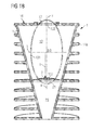
- the Figure 1A shows a schematic sectional view of a lamp housing for an embodiment of a lamp described here.
- the lamp housing 1 comprises a main body 11.
- the main body 11 is formed, for example, with a metal.
- the main body 11 is formed in a first portion in the manner of a truncated cone, in a second portion it is formed in the manner of a cylinder.
- the main body 11 comprises cooling disks 14a which are fastened to the main body in a cylindrical manner and spaced apart in a vertical direction from one another.
- the cooling disks 14a are integrally formed with the base body 11.
- the cooling disks 14a increase the outer surface of the Base body 11 and thus the lamp housing 1 and therefore serve to dissipate generated during operation of the lamp heat.
- the cooling disks 14a can each surround the main body 11 in each case completely as rings laterally.
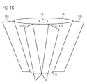
- cooling fins 14b are radially spaced fixed to the base body 11 and extend in the vertical direction, see the schematic perspective view of Figure 1C ,
- the cooling fins 14b may be formed rectangular, for example, in each case.
- a combination of cooling fins 14b and cooling disks 14a is possible.
- the main body 11 further comprises a first cavity 13.
- the first cavity 13 has an inner wall 131, which is designed to be reflective for visible light.
- the inner wall 131 of the first hollow body 13 is formed at least in places in the form of an ellipsoid of revolution.
- the ellipsoid of revolution has a first focal point 132 and a second focal point 133.
- the hollow body 13 is open on its longitudinal sides, that is to say in the region of the focal points 132, 133.
- the light source of the first type 2 is arranged at the first focal point 132.
- a light exit opening of the light source 2 lies in the same plane as the first focal point 132.
- Light exit opening 12 which is formed for example by an opening in the base body 11, which may be covered with a glass plate.
- a plane that terminates the light exit opening 12 also includes the second focal point 133.
- the light exit opening 12 has a diameter d, which is, for example, the maximum diameter of the light exit opening.
- the diameter d is, for example, in the range between 25 mm and 35 mm, in this case 30 mm.
- the light source 2 comprises a heat sink 21 and LED chips 22, 23 (see the FIGS. 2A to 2F ). In operation, electromagnetic radiation generated by the light source of the first type 2 is reflected on the inner walls 131 of the first cavity 13 in the direction of the light exit opening 12 and exits there to the outside.
- the light source of the first type 2 may then be, for example, a light module which itself comprises an optical element for beam shaping and / or beam guidance.
- the first cavity 13 is then a container which receives the light module.
- the outer surface 16 of the main body 11, which surrounds the light exit opening 12, may be designed to be reflective.
- the width of the lamp housing B is for example between 110 mm and 130 mm, in this case 120 mm.
- the height H1 of the lamp housing 1, that is to say the distance between the outer surface 16 and the surface of the lamp housing 1 opposite the outer surface, is for example between 250 mm and 270 mm, in the present case 260 mm.
- the main body 11 of the lamp housing 1 has a second cavity 15.
- a drive device 5 may be provided for electrically operating and driving the light sources of the lamp.
- a lamp housing 1 is explained in more detail for a further embodiment of a lamp described here.
- the entire base body 11 is formed as a truncated cone, which tapers in a direction away from the light exit opening 12.
- the formation of the first cavity 13 is described in more detail as an ellipsoid of revolution.
- the ellipsoid of revolution has the axes a, b, which are selected, for example, in the ratio 2: 1.
- the ratio of the focal length f to the small axis b is then approximately 1.73: 1.
- the cavity 13 with its reflective inner wall 131 as an ellipsoid, a particularly good mixing of the light of the light source 2 takes place before the light exit through the light exit opening 12.
- the light exit opening 12, which is arranged in the region of the second focal point 132 can be selected to be relatively small.
- the maximum diameter d of the light exit opening 12 is at most twice as large as the maximum diameter d2 of the light exit surface of the light source of the first type 2.
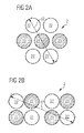
- FIG. 2A is a schematic plan view of a light source of the first type 2 shown, as used in one embodiment of a lamp described herein.
- the light source 2 comprises four first light-emitting diode chips 22 and three second light-emitting diode chips 23.
- the first type light source 2 may comprise eight light emitting diode chips, for example, four red light emitting LED chips 23 and four green blue light emitting LED chips 22. It is also it is conceivable that the light source of the first type 2 comprises seven light-emitting diode chips, for example two red light-emitting light-emitting diode chips, two amber light-emitting light-emitting diode chips and three blue-green light-emitting light-emitting diode chips.
- the light source of the first type 2 is operated, for example, with a current of 700 mA and generates a waste heat of at least 10 W, for example approximately 15 W.
- the lamp housing 1 is suitable, for example due to the cooling rings 14 on the base body 15, to dissipate this waste heat.
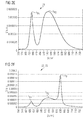
- FIGS. 2C to 2F spectra are plotted in each case graphically, wherein the intensity I in arbitrary units against the wavelength A in nm is plotted.
- the Figure 2C shows in a graph of the spectrum of second LED chips 23 having a peak wavelength ⁇ P in the range of red light.
- the Figures 2D and 2E show two possibilities for the first LED chips 22, each having peak wavelengths in the range of blue ⁇ P1 and green light ⁇ P2.
- the Figure 2F shows a resulting spectrum, for example in the combination of LED chips 22, 23, as shown in FIG. 2B are arranged and the spectra of the Figure 2C and 2D exhibit.
- the color rendering index Ra of such a light source of the first type 2 is approximately 86.
- the light emitted by the light source of the first type 2 has a color rendering index Ra of at least 80.
- the color temperature of the light emitted by the light source of the first type 2 is, for example, at least 2700 K, in the present case approximately 2950 K.
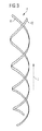
- FIG. 3 shows a holder 4, the two rods 41, 42 extending along its main axis of extension z extend. Both rods 41, 42 are each formed as a helix.
- the rod 42 goes out of the rod 41, for example, by a rotation through 180 ° about the main extension axis z.
- the holder 4 forms a sautémony screw, which is formed with two helices 41, 42.
- the holder 4 is mechanically fastened to the lamp housing 1.
- the rods 41, 42 wind in this way around the main emission direction R of the light source of the first type 2, which runs parallel to the main extension axis z of the rods 41, 42.
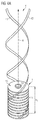
- the lamp comprises the lamp housing 1 with the light exit opening 12.
- the rods 41, 42 of the holder 4 serve as a power supply for the light sources of the second kind.
- the lamp includes, for example, six light sources of the second type, each formed by organic light-emitting diodes.
- the light sources of the second type 3 comprise an emission side 31, from which electromagnetic radiation is actively radiated by the light sources of the second type 3.
- the light sources of the second type 3 emit white light at a color temperature of between 2700 K and 2900 K, in this case 2800 K.
- the light sources of the second type 3 furthermore comprise a rear side 32 facing away from the emission side, which is designed to be reflective in the present case.
- the emission side 31 may be reflective, so that the light sources of the second type 3 reflect light of the light source of the first type 2, which exits through the light exit opening 12 of the lamp housing 1.
- the light sources of the second type 3 are rotatably mounted about the axes of rotation 6 and fixed to both rods 41, 42 of the holder 4. Due to the design of the holder 4 as a double-threaded screw can - with a suitable arrangement of the light sources of the second type 3 - light from the light source of the first type 2 to reach each light source of the second type 3.
- the height H2 of the holder is presently at least 200 mm, for example 920 mm.
- the arrangement of the light sources of the second type 3 between the rods 41, 42 of the holder 4 also leads to a mechanical stabilization of the holder 4.
- About rotation about the axes of rotation 6 of the light sources of the second type 3 a radiation characteristic of the lamp can be adjusted relatively freely.
- the light sources of the second type 3 Due to the illumination of the light sources of the second type 3 with the light of the light source of the first type 2, the light sources of the second type 3 appear altogether brighter. It gives the impression that the entire emitted light of the lamp originates from the light sources of the second kind 3.
- the light sources of the second type 3 are designed to be reflective at least in places, it is also possible that the light sources of the second type 3 are radiation-transmissive and emit electromagnetic radiation both from their front side 31 and from their rear side 32. The light sources of the second type 3 are then irradiated by the light of the light source of the first type 2. This also gives the impression that the entire light generated by the lamp during operation comes from the light sources of the second type 3.
Landscapes
- Engineering & Computer Science (AREA)
- General Engineering & Computer Science (AREA)
- Physics & Mathematics (AREA)
- Microelectronics & Electronic Packaging (AREA)
- Optics & Photonics (AREA)
- Geometry (AREA)
- Non-Portable Lighting Devices Or Systems Thereof (AREA)
- Fastening Of Light Sources Or Lamp Holders (AREA)
- Arrangement Of Elements, Cooling, Sealing, Or The Like Of Lighting Devices (AREA)
Claims (13)
- Lampe, comprenant- un boîtier de lampe (1), qui présente une ouverture de sortie de la lumière (12),- une source de lumière d'un premier type (2), qui est disposée dans le boîtier de lampe (1),- une fixation (4), qui est fixée au boîtier de lampe (1),- au moins une source de lumière d'un deuxième type (3), qui est fixée à la fixation (4),- l'au moins une source de lumière d'un deuxième type (3) étant disposée après l'ouverture de sortie de la lumière (12) dans une direction de rayonnement (R), caractérisée en ce que- la fixation (4) comprend au moins deux tiges (41, 42) entre lesquelles est supportée à rotation l'au moins une source de lumière d'un deuxième type (3),- l'allure d'une deuxième tige (42) des au moins deux tiges (41, 42) résulte de l'allure d'une première tige (41) des au moins deux tiges (41, 42) et d'une rotation autour de l'axe d'étendue principale de la première tige (41), et- l'au moins une source de lumière d'un deuxième type (3) comprend une diode électroluminescente organique.
- Lampe selon la revendication précédente,- dans laquelle au moins l'une de l'au moins une source de lumière d'un deuxième type (3) est réalisée de manière réfléchissante au moins en partie, et la lumière émise lors du fonctionnement de la source de lumière d'un premier type (2) tombe sur cette source de lumière d'un deuxième type (3) et est réfléchie par celle-ci.
- Lampe selon l'une quelconque des revendications précédentes,- dans laquelle au moins l'une de l'au moins une source de lumière d'un deuxième type (3) est réalisée de manière au moins en partie transparente au rayonnement, et la lumière émise lors du fonctionnement de la source de lumière d'un premier type (2) tombe sur cette source de lumière d'un deuxième type (3) et la traverse.
- Lampe selon l'une quelconque des revendications précédentes,- dans laquelle le boîtier de lampe (1) présente une première cavité (13) dans laquelle est disposée la source de lumière d'un premier type (2), une surface interne (131) de la première cavité tournée vers la source de lumière d'un premier type (2) étant réalisée sous forme réfléchissante.
- Lampe selon l'une quelconque des revendications précédentes,- dans laquelle le boîtier de lampe (1) présente une première cavité (13) qui est réalisée en partie sous forme d'ellipsoïde de révolution, la source de lumière d'un premier type (2) étant disposée aux environs d'un foyer (132) de l'ellipsoïde de révolution, lequel est opposé à l'ouverture de sortie de la lumière (12), et l'ouverture de sortie de la lumière (12) est disposée aux environs de l'autre foyer (133) de l'ellipsoïde de révolution.
- Lampe selon l'une quelconque des revendications précédentes,- dans laquelle le boîtier de lampe (1) présente une deuxième cavité (15) qui est disposée au niveau d'un côté de la première cavité (13) opposé à l'ouverture de sortie de la lumière (12), un dispositif de commande (5) pour les sources de lumière (2, 3) étant disposé dans la deuxième cavité (15).
- Lampe selon l'une quelconque des revendications précédentes,- dans laquelle le boîtier de lampe (1) présente un corps de base (11) qui est réalisé au moins en partie à la manière d'un tronc de cône ou d'un tronc de pyramide, le tronc de cône ou le tronc de pyramide se rétrécissant en s'éloignant de l'ouverture de sortie de la lumière (12).
- Lampe selon l'une quelconque des revendications précédentes,- dans laquelle le boîtier de lampe (1) présente un corps de base (11) et au moins deux disques de refroidissement (14a) et/ou ailettes de refroidissement (14b), les disques de refroidissement (14a) et/ou les ailettes de refroidissement (14b) étant fixé (e) s de manière espacée sur le corps de base (11) et entourant latéralement le corps de base (11).
- Lampe selon l'une quelconque des revendications précédentes,- dans laquelle la surface extérieure (16) du boîtier de lampe (1) entourant l'ouverture de sortie de la lumière (12) est réalisée au mois en partie de manière réfléchissante.
- Lampe selon l'une quelconque des revendications précédentes,- dans laquelle la fixation (4) sert au raccord électrique de l'au moins une source de lumière d'un deuxième type (3).
- Lampe selon l'une quelconque des revendications précédentes,- dans laquelle l'au moins une source de lumière d'un deuxième type (3) est supportée à rotation.
- Lampe selon l'une quelconque des revendications précédentes,- dans laquelle la fixation (4) comprend au moins une tige (41, 42), qui est réalisée au moins en partie à la manière d'une fonction sinusoïdale et/ou à la manière d'une fonction cosinus.
- Lampe selon l'une quelconque des revendications précédentes,
dans laquelle la fixation (4) est réalisée à la manière d'une vis à deux pas, la fixation (4) comprenant deux tiges (41, 42) qui sont réalisées à chaque fois sous forme d'hélice.
Applications Claiming Priority (2)
| Application Number | Priority Date | Filing Date | Title |
|---|---|---|---|
| DE102009038864.8A DE102009038864B4 (de) | 2009-08-27 | 2009-08-27 | Lampe zur Allgemeinbeleuchtung |
| PCT/EP2010/061785 WO2011023569A1 (fr) | 2009-08-27 | 2010-08-12 | Lampe d'éclairage général |
Publications (2)
| Publication Number | Publication Date |
|---|---|
| EP2470825A1 EP2470825A1 (fr) | 2012-07-04 |
| EP2470825B1 true EP2470825B1 (fr) | 2016-03-30 |
Family
ID=43014512
Family Applications (1)
| Application Number | Title | Priority Date | Filing Date |
|---|---|---|---|
| EP10741991.3A Active EP2470825B1 (fr) | 2009-08-27 | 2010-08-12 | Lampe d'éclairage général |
Country Status (7)
| Country | Link |
|---|---|
| US (2) | US8876332B2 (fr) |
| EP (1) | EP2470825B1 (fr) |
| JP (2) | JP5490900B2 (fr) |
| KR (1) | KR101749654B1 (fr) |
| CN (1) | CN102483206B (fr) |
| DE (1) | DE102009038864B4 (fr) |
| WO (1) | WO2011023569A1 (fr) |
Families Citing this family (5)
| Publication number | Priority date | Publication date | Assignee | Title |
|---|---|---|---|---|
| DE102009038864B4 (de) * | 2009-08-27 | 2021-11-25 | Pictiva Displays International Limited | Lampe zur Allgemeinbeleuchtung |
| DE102012103093A1 (de) | 2012-04-11 | 2013-10-17 | Osram Opto Semiconductors Gmbh | Leuchte und Leuchten-Anordnung |
| CN104154490A (zh) * | 2014-07-15 | 2014-11-19 | 无锡启晖光电科技有限公司 | 一种舞台灯/投影灯二次反光装置 |
| CN105757611B (zh) * | 2014-12-18 | 2017-11-17 | 北京欣天和怡机电设备安装工程有限公司 | 双椭球反光器、led发光装置以及灯具 |
| KR101852375B1 (ko) * | 2015-12-30 | 2018-06-12 | 엘지전자 주식회사 | 차량의 램프 장치 |
Family Cites Families (40)
| Publication number | Priority date | Publication date | Assignee | Title |
|---|---|---|---|---|
| DE2930383C2 (de) * | 1979-07-26 | 1983-01-20 | Optische Werke G. Rodenstock, 8000 München | Leuchtdiodenanordnung |
| JPS56131614U (fr) | 1980-03-07 | 1981-10-06 | ||
| USD274270S (en) | 1982-07-12 | 1984-06-12 | Anthony Pitti | Lamp base |
| USD282290S (en) | 1982-09-17 | 1986-01-21 | Tobia Scarpa | Table lamp |
| JPH0328472Y2 (fr) | 1985-05-17 | 1991-06-19 | ||
| JPH0430722Y2 (fr) | 1985-05-27 | 1992-07-24 | ||
| DE8607738U1 (de) | 1986-03-20 | 1986-05-28 | Schlagheck, Norbert, Prof., 82284 Grafrath | Leuchtenträger |
| JPS63150807A (ja) | 1986-12-18 | 1988-06-23 | 中松 義郎 | フロアスタンド |
| JPH0160405U (fr) | 1987-10-12 | 1989-04-17 | ||
| FR2657680B1 (fr) | 1990-01-26 | 1993-02-05 | Valeo Vision | Projecteur de vehicule automobile comportant une source lumineuse perfectionnee. |
| USD327136S (en) | 1990-09-14 | 1992-06-16 | Zachary Tunick | Floor lamp |
| US5829866A (en) * | 1996-02-26 | 1998-11-03 | U.S. Philips Corporation | Street light luminaire |
| USD388198S (en) | 1997-01-15 | 1997-12-23 | Virginia Tech Intellectual Properties, Inc. | Fiber optic accent light |
| KR200252925Y1 (ko) | 1999-06-30 | 2001-11-15 | 박완진 | 회전식 스탠드 |
| CA2361528A1 (fr) * | 1999-12-02 | 2001-06-07 | Matsushita Electric Industrial Co., Ltd. | Lampe a decharge et dispositif de lampe |
| USD443716S1 (en) | 2000-03-02 | 2001-06-12 | L.A. Product Design, L.L.C. | Lamp stand |
| KR200212762Y1 (ko) | 2000-09-02 | 2001-02-15 | 강달형 | 내부 회전부를 갖는 스탠드 |
| US6578998B2 (en) * | 2001-03-21 | 2003-06-17 | A L Lightech, Inc. | Light source arrangement |
| US6899448B2 (en) * | 2003-01-21 | 2005-05-31 | Athinos Lighting, Llc | Theme-based illuminating mobile |
| KR200318162Y1 (ko) | 2003-03-20 | 2003-06-28 | 이레텍전자 주식회사 | 다기능 조명 기구 |
| US6861669B2 (en) * | 2003-03-31 | 2005-03-01 | Agilent Technologies, Inc. | Compound display |
| CN100452424C (zh) * | 2003-05-13 | 2009-01-14 | 光处方革新有限公司 | 用作基于led的灯泡替代物的光学设备 |
| US7021797B2 (en) | 2003-05-13 | 2006-04-04 | Light Prescriptions Innovators, Llc | Optical device for repositioning and redistributing an LED's light |
| US7857496B2 (en) * | 2004-03-05 | 2010-12-28 | Osram Gesellschaft mit beschränkter Haftung | Lamp |
| JP2006196196A (ja) | 2005-01-11 | 2006-07-27 | Pentax Corp | 車両用ヘッドライト |
| USD523987S1 (en) | 2005-02-01 | 2006-06-27 | Dolan Patrick S | Table lamp |
| JP2008010382A (ja) * | 2006-05-30 | 2008-01-17 | Ushio Inc | 光源装置 |
| US20080007936A1 (en) * | 2006-07-05 | 2008-01-10 | Jie Liu | Organic illumination source and method for controlled illumination |
| ITFI20060204A1 (it) * | 2006-08-09 | 2008-02-10 | Targetti Sankey Spa | Lampada e dispositivo antidispersione luminosa in direzioni indesiderate |
| USD570004S1 (en) | 2006-08-11 | 2008-05-27 | Target Brands, Inc. | Light display fixture |
| WO2008040323A2 (fr) | 2006-09-29 | 2008-04-10 | Osram Opto Semiconductors Gmbh | Dispositif organique luminescent et dispositif d'éclairage |
| DE102006060781B4 (de) * | 2006-09-29 | 2021-09-16 | Pictiva Displays International Limited | Organisches Leuchtmittel |
| EP2122235B1 (fr) * | 2007-01-24 | 2017-03-22 | Philips Lighting Holding B.V. | Dispositif d'éclairage comprenant au moins une lampe et au moins une oled (diode électroluminescente organique) |
| JP4859857B2 (ja) | 2008-02-29 | 2012-01-25 | 財団法人山形県産業技術振興機構 | 照明装置 |
| DE102008019926B4 (de) * | 2008-04-21 | 2011-07-07 | Fraunhofer-Gesellschaft zur Förderung der angewandten Forschung e.V., 80686 | Beleuchtungsvorrichtung und Verfahren zur Erzeugung einer flächigen Lichtausgabe |
| DE102008036487B4 (de) * | 2008-08-05 | 2016-12-15 | Osram Opto Semiconductors Gmbh | Leuchtmittel und Verwendung eines Leuchtmittels |
| DE102008057606A1 (de) * | 2008-11-17 | 2010-05-20 | Tridonicatco Gmbh & Co. Kg | Kombinationsleuchte |
| US7993039B2 (en) * | 2009-03-27 | 2011-08-09 | Hubbell Incorporated | Lighting fixture having a latching system and an auxiliary emergency light |
| DE102009038864B4 (de) * | 2009-08-27 | 2021-11-25 | Pictiva Displays International Limited | Lampe zur Allgemeinbeleuchtung |
| USD634881S1 (en) | 2009-09-04 | 2011-03-22 | Osram Gmbh | Light |
-
2009
- 2009-08-27 DE DE102009038864.8A patent/DE102009038864B4/de active Active
-
2010
- 2010-08-12 JP JP2012525991A patent/JP5490900B2/ja not_active Expired - Fee Related
- 2010-08-12 KR KR1020127007849A patent/KR101749654B1/ko active IP Right Grant
- 2010-08-12 WO PCT/EP2010/061785 patent/WO2011023569A1/fr active Application Filing
- 2010-08-12 US US13/392,618 patent/US8876332B2/en active Active
- 2010-08-12 EP EP10741991.3A patent/EP2470825B1/fr active Active
- 2010-08-12 CN CN201080038138.0A patent/CN102483206B/zh active Active
-
2014
- 2014-02-26 JP JP2014035136A patent/JP5781178B2/ja not_active Expired - Fee Related
- 2014-09-10 US US14/482,007 patent/US9746137B2/en active Active
Also Published As
| Publication number | Publication date |
|---|---|
| KR20120066030A (ko) | 2012-06-21 |
| WO2011023569A1 (fr) | 2011-03-03 |
| CN102483206A (zh) | 2012-05-30 |
| JP2013503421A (ja) | 2013-01-31 |
| US8876332B2 (en) | 2014-11-04 |
| US20120188764A1 (en) | 2012-07-26 |
| DE102009038864A1 (de) | 2011-03-03 |
| JP5781178B2 (ja) | 2015-09-16 |
| JP5490900B2 (ja) | 2014-05-14 |
| KR101749654B1 (ko) | 2017-06-21 |
| CN102483206B (zh) | 2014-08-20 |
| US20140376225A1 (en) | 2014-12-25 |
| US9746137B2 (en) | 2017-08-29 |
| EP2470825A1 (fr) | 2012-07-04 |
| JP2014130835A (ja) | 2014-07-10 |
| DE102009038864B4 (de) | 2021-11-25 |
Similar Documents
| Publication | Publication Date | Title |
|---|---|---|
| EP2049835B1 (fr) | Lampe | |
| DE69937993T2 (de) | Beleuchtungsanordnung | |
| EP2207996B1 (fr) | Lampe led à diffuseur | |
| DE102012112192B3 (de) | Bestrahlungsvorrichtung zur Bestrahlung von Pflanzen | |
| DE102010043921B4 (de) | Leuchtvorrichtung und Verfahren zum Herstellen einer Leuchtvorrichtung | |
| EP2470825B1 (fr) | Lampe d'éclairage général | |
| DE102010014307A1 (de) | Beleuchtungseinrichtung | |
| DE102010030296B4 (de) | Lampe mit konkavem Reflektor und einem Vorsprung für mindestens eine Lichtquelle | |
| DE102009012138A1 (de) | LED-Beleuchtungsvorrichtung | |
| DE102009047487A1 (de) | Leuchtmodul | |
| EP1555477A1 (fr) | Luminaire comprenant des sources lumineuses de différentes couleurs ainsi qu'un guide de lumière plan pour émettre un mélange de lumières | |
| DE102017116885A1 (de) | Leuchtmittel und Linse für ein Leuchtmittel | |
| EP2360427A2 (fr) | Réflecteur tri-zone | |
| DE102011086713A1 (de) | Leuchtvorrichtung mit Halbleiterlichtquelle und beanstandetem Leuchtstoffbereich | |
| EP2863112A1 (fr) | Lampe d'opération à LED | |
| DE102012211936A1 (de) | Vorrichtung zum bereitstellen elektromagnetischer strahlung | |
| DE112013006624T5 (de) | Beleuchtungsvorrichtung | |
| WO2012103919A1 (fr) | Dispositif d'éclairage à élément fluorescent et système optique | |
| DE102011081459B4 (de) | Leuchtanordnung mit multiplen Fernfeldern | |
| DE102012205465A1 (de) | Leuchtvorrichtung | |
| DE102010042631A1 (de) | Entladungslampe mit einem mehrfach gewundenen Entladungsgefäß sowie Entblendungselement für eine Entladungslampe | |
| WO2019149893A1 (fr) | Dispositif de génération de lumiere | |
| EP1621809A1 (fr) | Corps lumineux | |
| DE202016103386U1 (de) | Leuchte, insbesondere Downlight- und/oder Spotlight-Leuchte, mit einer Lichtquelle | |
| DE102007034373B4 (de) | Signalleuchte |
Legal Events
| Date | Code | Title | Description |
|---|---|---|---|
| PUAI | Public reference made under article 153(3) epc to a published international application that has entered the european phase |
Free format text: ORIGINAL CODE: 0009012 |
|
| 17P | Request for examination filed |
Effective date: 20120209 |
|
| AK | Designated contracting states |
Kind code of ref document: A1 Designated state(s): AL AT BE BG CH CY CZ DE DK EE ES FI FR GB GR HR HU IE IS IT LI LT LU LV MC MK MT NL NO PL PT RO SE SI SK SM TR |
|
| DAX | Request for extension of the european patent (deleted) | ||
| 17Q | First examination report despatched |
Effective date: 20141114 |
|
| RAP1 | Party data changed (applicant data changed or rights of an application transferred) |
Owner name: OSRAM OLED GMBH |
|
| GRAP | Despatch of communication of intention to grant a patent |
Free format text: ORIGINAL CODE: EPIDOSNIGR1 |
|
| RIC1 | Information provided on ipc code assigned before grant |
Ipc: F21Y 113/02 20060101ALN20151001BHEP Ipc: F21S 6/00 20060101ALI20151001BHEP Ipc: F21Y 101/02 20060101ALN20151001BHEP Ipc: F21S 8/00 20060101AFI20151001BHEP Ipc: F21Y 105/00 20060101ALN20151001BHEP |
|
| INTG | Intention to grant announced |
Effective date: 20151019 |
|
| GRAS | Grant fee paid |
Free format text: ORIGINAL CODE: EPIDOSNIGR3 |
|
| GRAA | (expected) grant |
Free format text: ORIGINAL CODE: 0009210 |
|
| RIN1 | Information on inventor provided before grant (corrected) |
Inventor name: MOECK, MARTIN |
|
| RIC1 | Information provided on ipc code assigned before grant |
Ipc: F21Y 113/20 20160101ALN20160210BHEP Ipc: F21Y 115/10 20160101ALN20160210BHEP Ipc: F21S 6/00 20060101ALI20160210BHEP Ipc: F21S 8/00 20060101AFI20160210BHEP Ipc: F21Y 115/15 20160101ALN20160210BHEP |
|
| AK | Designated contracting states |
Kind code of ref document: B1 Designated state(s): AL AT BE BG CH CY CZ DE DK EE ES FI FR GB GR HR HU IE IS IT LI LT LU LV MC MK MT NL NO PL PT RO SE SI SK SM TR |
|
| REG | Reference to a national code |
Ref country code: GB Ref legal event code: FG4D Free format text: NOT ENGLISH |
|
| REG | Reference to a national code |
Ref country code: CH Ref legal event code: EP |
|
| REG | Reference to a national code |
Ref country code: AT Ref legal event code: REF Ref document number: 785791 Country of ref document: AT Kind code of ref document: T Effective date: 20160415 |
|
| REG | Reference to a national code |
Ref country code: IE Ref legal event code: FG4D Free format text: LANGUAGE OF EP DOCUMENT: GERMAN |
|
| REG | Reference to a national code |
Ref country code: DE Ref legal event code: R096 Ref document number: 502010011346 Country of ref document: DE |
|
| REG | Reference to a national code |
Ref country code: LT Ref legal event code: MG4D |
|
| PG25 | Lapsed in a contracting state [announced via postgrant information from national office to epo] |
Ref country code: HR Free format text: LAPSE BECAUSE OF FAILURE TO SUBMIT A TRANSLATION OF THE DESCRIPTION OR TO PAY THE FEE WITHIN THE PRESCRIBED TIME-LIMIT Effective date: 20160330 Ref country code: FI Free format text: LAPSE BECAUSE OF FAILURE TO SUBMIT A TRANSLATION OF THE DESCRIPTION OR TO PAY THE FEE WITHIN THE PRESCRIBED TIME-LIMIT Effective date: 20160330 Ref country code: GR Free format text: LAPSE BECAUSE OF FAILURE TO SUBMIT A TRANSLATION OF THE DESCRIPTION OR TO PAY THE FEE WITHIN THE PRESCRIBED TIME-LIMIT Effective date: 20160701 Ref country code: NO Free format text: LAPSE BECAUSE OF FAILURE TO SUBMIT A TRANSLATION OF THE DESCRIPTION OR TO PAY THE FEE WITHIN THE PRESCRIBED TIME-LIMIT Effective date: 20160630 |
|
| REG | Reference to a national code |
Ref country code: NL Ref legal event code: MP Effective date: 20160330 |
|
| REG | Reference to a national code |
Ref country code: FR Ref legal event code: PLFP Year of fee payment: 7 |
|
| PG25 | Lapsed in a contracting state [announced via postgrant information from national office to epo] |
Ref country code: LT Free format text: LAPSE BECAUSE OF FAILURE TO SUBMIT A TRANSLATION OF THE DESCRIPTION OR TO PAY THE FEE WITHIN THE PRESCRIBED TIME-LIMIT Effective date: 20160330 Ref country code: LV Free format text: LAPSE BECAUSE OF FAILURE TO SUBMIT A TRANSLATION OF THE DESCRIPTION OR TO PAY THE FEE WITHIN THE PRESCRIBED TIME-LIMIT Effective date: 20160330 Ref country code: SE Free format text: LAPSE BECAUSE OF FAILURE TO SUBMIT A TRANSLATION OF THE DESCRIPTION OR TO PAY THE FEE WITHIN THE PRESCRIBED TIME-LIMIT Effective date: 20160330 |
|
| PG25 | Lapsed in a contracting state [announced via postgrant information from national office to epo] |
Ref country code: NL Free format text: LAPSE BECAUSE OF FAILURE TO SUBMIT A TRANSLATION OF THE DESCRIPTION OR TO PAY THE FEE WITHIN THE PRESCRIBED TIME-LIMIT Effective date: 20160330 |
|
| PG25 | Lapsed in a contracting state [announced via postgrant information from national office to epo] |
Ref country code: IS Free format text: LAPSE BECAUSE OF FAILURE TO SUBMIT A TRANSLATION OF THE DESCRIPTION OR TO PAY THE FEE WITHIN THE PRESCRIBED TIME-LIMIT Effective date: 20160730 Ref country code: PL Free format text: LAPSE BECAUSE OF FAILURE TO SUBMIT A TRANSLATION OF THE DESCRIPTION OR TO PAY THE FEE WITHIN THE PRESCRIBED TIME-LIMIT Effective date: 20160330 Ref country code: EE Free format text: LAPSE BECAUSE OF FAILURE TO SUBMIT A TRANSLATION OF THE DESCRIPTION OR TO PAY THE FEE WITHIN THE PRESCRIBED TIME-LIMIT Effective date: 20160330 |
|
| PG25 | Lapsed in a contracting state [announced via postgrant information from national office to epo] |
Ref country code: RO Free format text: LAPSE BECAUSE OF FAILURE TO SUBMIT A TRANSLATION OF THE DESCRIPTION OR TO PAY THE FEE WITHIN THE PRESCRIBED TIME-LIMIT Effective date: 20160330 Ref country code: PT Free format text: LAPSE BECAUSE OF FAILURE TO SUBMIT A TRANSLATION OF THE DESCRIPTION OR TO PAY THE FEE WITHIN THE PRESCRIBED TIME-LIMIT Effective date: 20160801 Ref country code: SM Free format text: LAPSE BECAUSE OF FAILURE TO SUBMIT A TRANSLATION OF THE DESCRIPTION OR TO PAY THE FEE WITHIN THE PRESCRIBED TIME-LIMIT Effective date: 20160330 Ref country code: CZ Free format text: LAPSE BECAUSE OF FAILURE TO SUBMIT A TRANSLATION OF THE DESCRIPTION OR TO PAY THE FEE WITHIN THE PRESCRIBED TIME-LIMIT Effective date: 20160330 Ref country code: ES Free format text: LAPSE BECAUSE OF FAILURE TO SUBMIT A TRANSLATION OF THE DESCRIPTION OR TO PAY THE FEE WITHIN THE PRESCRIBED TIME-LIMIT Effective date: 20160330 Ref country code: SK Free format text: LAPSE BECAUSE OF FAILURE TO SUBMIT A TRANSLATION OF THE DESCRIPTION OR TO PAY THE FEE WITHIN THE PRESCRIBED TIME-LIMIT Effective date: 20160330 |
|
| PG25 | Lapsed in a contracting state [announced via postgrant information from national office to epo] |
Ref country code: BE Free format text: LAPSE BECAUSE OF NON-PAYMENT OF DUE FEES Effective date: 20160831 Ref country code: IT Free format text: LAPSE BECAUSE OF FAILURE TO SUBMIT A TRANSLATION OF THE DESCRIPTION OR TO PAY THE FEE WITHIN THE PRESCRIBED TIME-LIMIT Effective date: 20160330 |
|
| REG | Reference to a national code |
Ref country code: DE Ref legal event code: R097 Ref document number: 502010011346 Country of ref document: DE |
|
| PG25 | Lapsed in a contracting state [announced via postgrant information from national office to epo] |
Ref country code: DK Free format text: LAPSE BECAUSE OF FAILURE TO SUBMIT A TRANSLATION OF THE DESCRIPTION OR TO PAY THE FEE WITHIN THE PRESCRIBED TIME-LIMIT Effective date: 20160330 |
|
| PLBE | No opposition filed within time limit |
Free format text: ORIGINAL CODE: 0009261 |
|
| STAA | Information on the status of an ep patent application or granted ep patent |
Free format text: STATUS: NO OPPOSITION FILED WITHIN TIME LIMIT |
|
| 26N | No opposition filed |
Effective date: 20170103 |
|
| PG25 | Lapsed in a contracting state [announced via postgrant information from national office to epo] |
Ref country code: MC Free format text: LAPSE BECAUSE OF FAILURE TO SUBMIT A TRANSLATION OF THE DESCRIPTION OR TO PAY THE FEE WITHIN THE PRESCRIBED TIME-LIMIT Effective date: 20160330 |
|
| REG | Reference to a national code |
Ref country code: CH Ref legal event code: PL |
|
| PG25 | Lapsed in a contracting state [announced via postgrant information from national office to epo] |
Ref country code: LI Free format text: LAPSE BECAUSE OF NON-PAYMENT OF DUE FEES Effective date: 20160831 Ref country code: CH Free format text: LAPSE BECAUSE OF NON-PAYMENT OF DUE FEES Effective date: 20160831 |
|
| PG25 | Lapsed in a contracting state [announced via postgrant information from national office to epo] |
Ref country code: SI Free format text: LAPSE BECAUSE OF FAILURE TO SUBMIT A TRANSLATION OF THE DESCRIPTION OR TO PAY THE FEE WITHIN THE PRESCRIBED TIME-LIMIT Effective date: 20160330 |
|
| REG | Reference to a national code |
Ref country code: IE Ref legal event code: MM4A |
|
| PG25 | Lapsed in a contracting state [announced via postgrant information from national office to epo] |
Ref country code: IE Free format text: LAPSE BECAUSE OF NON-PAYMENT OF DUE FEES Effective date: 20160812 |
|
| REG | Reference to a national code |
Ref country code: FR Ref legal event code: PLFP Year of fee payment: 8 |
|
| PG25 | Lapsed in a contracting state [announced via postgrant information from national office to epo] |
Ref country code: LU Free format text: LAPSE BECAUSE OF NON-PAYMENT OF DUE FEES Effective date: 20160812 |
|
| REG | Reference to a national code |
Ref country code: AT Ref legal event code: MM01 Ref document number: 785791 Country of ref document: AT Kind code of ref document: T Effective date: 20160812 |
|
| PG25 | Lapsed in a contracting state [announced via postgrant information from national office to epo] |
Ref country code: AT Free format text: LAPSE BECAUSE OF NON-PAYMENT OF DUE FEES Effective date: 20160812 |
|
| PGFP | Annual fee paid to national office [announced via postgrant information from national office to epo] |
Ref country code: GB Payment date: 20170822 Year of fee payment: 8 Ref country code: FR Payment date: 20170822 Year of fee payment: 8 |
|
| PG25 | Lapsed in a contracting state [announced via postgrant information from national office to epo] |
Ref country code: CY Free format text: LAPSE BECAUSE OF FAILURE TO SUBMIT A TRANSLATION OF THE DESCRIPTION OR TO PAY THE FEE WITHIN THE PRESCRIBED TIME-LIMIT Effective date: 20160330 Ref country code: HU Free format text: LAPSE BECAUSE OF FAILURE TO SUBMIT A TRANSLATION OF THE DESCRIPTION OR TO PAY THE FEE WITHIN THE PRESCRIBED TIME-LIMIT; INVALID AB INITIO Effective date: 20100812 |
|
| PG25 | Lapsed in a contracting state [announced via postgrant information from national office to epo] |
Ref country code: MT Free format text: LAPSE BECAUSE OF FAILURE TO SUBMIT A TRANSLATION OF THE DESCRIPTION OR TO PAY THE FEE WITHIN THE PRESCRIBED TIME-LIMIT Effective date: 20160330 Ref country code: MK Free format text: LAPSE BECAUSE OF FAILURE TO SUBMIT A TRANSLATION OF THE DESCRIPTION OR TO PAY THE FEE WITHIN THE PRESCRIBED TIME-LIMIT Effective date: 20160330 Ref country code: TR Free format text: LAPSE BECAUSE OF FAILURE TO SUBMIT A TRANSLATION OF THE DESCRIPTION OR TO PAY THE FEE WITHIN THE PRESCRIBED TIME-LIMIT Effective date: 20160330 |
|
| PG25 | Lapsed in a contracting state [announced via postgrant information from national office to epo] |
Ref country code: BG Free format text: LAPSE BECAUSE OF FAILURE TO SUBMIT A TRANSLATION OF THE DESCRIPTION OR TO PAY THE FEE WITHIN THE PRESCRIBED TIME-LIMIT Effective date: 20160330 |
|
| PG25 | Lapsed in a contracting state [announced via postgrant information from national office to epo] |
Ref country code: AL Free format text: LAPSE BECAUSE OF FAILURE TO SUBMIT A TRANSLATION OF THE DESCRIPTION OR TO PAY THE FEE WITHIN THE PRESCRIBED TIME-LIMIT Effective date: 20160330 |
|
| GBPC | Gb: european patent ceased through non-payment of renewal fee |
Effective date: 20180812 |
|
| PG25 | Lapsed in a contracting state [announced via postgrant information from national office to epo] |
Ref country code: FR Free format text: LAPSE BECAUSE OF NON-PAYMENT OF DUE FEES Effective date: 20180831 |
|
| PG25 | Lapsed in a contracting state [announced via postgrant information from national office to epo] |
Ref country code: GB Free format text: LAPSE BECAUSE OF NON-PAYMENT OF DUE FEES Effective date: 20180812 |
|
| REG | Reference to a national code |
Ref country code: DE Ref legal event code: R081 Ref document number: 502010011346 Country of ref document: DE Owner name: PICTIVA DISPLAYS INTERNATIONAL LIMITED, IE Free format text: FORMER OWNER: OSRAM OLED GMBH, 93049 REGENSBURG, DE Ref country code: DE Ref legal event code: R082 Ref document number: 502010011346 Country of ref document: DE Representative=s name: EPPING HERMANN FISCHER PATENTANWALTSGESELLSCHA, DE |
|
| PGFP | Annual fee paid to national office [announced via postgrant information from national office to epo] |
Ref country code: DE Payment date: 20230823 Year of fee payment: 14 |