EP2470740B1 - Elektromagnetisch dichte Tür für eine Messkammer - Google Patents
Elektromagnetisch dichte Tür für eine Messkammer Download PDFInfo
- Publication number
- EP2470740B1 EP2470740B1 EP10745560.2A EP10745560A EP2470740B1 EP 2470740 B1 EP2470740 B1 EP 2470740B1 EP 10745560 A EP10745560 A EP 10745560A EP 2470740 B1 EP2470740 B1 EP 2470740B1
- Authority
- EP
- European Patent Office
- Prior art keywords
- door
- closure mechanism
- mechanism according
- hinge
- test chamber
- Prior art date
- Legal status (The legal status is an assumption and is not a legal conclusion. Google has not performed a legal analysis and makes no representation as to the accuracy of the status listed.)
- Active
Links
Images




Classifications
-
- E—FIXED CONSTRUCTIONS
- E06—DOORS, WINDOWS, SHUTTERS, OR ROLLER BLINDS IN GENERAL; LADDERS
- E06B—FIXED OR MOVABLE CLOSURES FOR OPENINGS IN BUILDINGS, VEHICLES, FENCES OR LIKE ENCLOSURES IN GENERAL, e.g. DOORS, WINDOWS, BLINDS, GATES
- E06B5/00—Doors, windows, or like closures for special purposes; Border constructions therefor
- E06B5/10—Doors, windows, or like closures for special purposes; Border constructions therefor for protection against air-raid or other war-like action; for other protective purposes
- E06B5/18—Doors, windows, or like closures for special purposes; Border constructions therefor for protection against air-raid or other war-like action; for other protective purposes against harmful radiation
-
- E—FIXED CONSTRUCTIONS
- E05—LOCKS; KEYS; WINDOW OR DOOR FITTINGS; SAFES
- E05D—HINGES OR SUSPENSION DEVICES FOR DOORS, WINDOWS OR WINGS
- E05D15/00—Suspension arrangements for wings
- E05D15/56—Suspension arrangements for wings with successive different movements
- E05D15/58—Suspension arrangements for wings with successive different movements with both swinging and sliding movements
-
- E—FIXED CONSTRUCTIONS
- E05—LOCKS; KEYS; WINDOW OR DOOR FITTINGS; SAFES
- E05D—HINGES OR SUSPENSION DEVICES FOR DOORS, WINDOWS OR WINGS
- E05D3/00—Hinges with pins
- E05D3/06—Hinges with pins with two or more pins
-
- E—FIXED CONSTRUCTIONS
- E05—LOCKS; KEYS; WINDOW OR DOOR FITTINGS; SAFES
- E05D—HINGES OR SUSPENSION DEVICES FOR DOORS, WINDOWS OR WINGS
- E05D3/00—Hinges with pins
- E05D3/06—Hinges with pins with two or more pins
- E05D3/18—Hinges with pins with two or more pins with sliding pins or guides
-
- E—FIXED CONSTRUCTIONS
- E05—LOCKS; KEYS; WINDOW OR DOOR FITTINGS; SAFES
- E05F—DEVICES FOR MOVING WINGS INTO OPEN OR CLOSED POSITION; CHECKS FOR WINGS; WING FITTINGS NOT OTHERWISE PROVIDED FOR, CONCERNED WITH THE FUNCTIONING OF THE WING
- E05F11/00—Man-operated mechanisms for operating wings, including those which also operate the fastening
- E05F11/02—Man-operated mechanisms for operating wings, including those which also operate the fastening for wings in general, e.g. fanlights
- E05F11/08—Man-operated mechanisms for operating wings, including those which also operate the fastening for wings in general, e.g. fanlights with longitudinally-moving bars guided, e.g. by pivoted links, in or on the frame
- E05F11/12—Mechanisms by which the bar shifts the wing
- E05F11/14—Mechanisms by which the bar shifts the wing directly, i.e. without links, shifting the wing, e.g. by rack and gear or pin and slot
- E05F11/145—Mechanisms by which the bar shifts the wing directly, i.e. without links, shifting the wing, e.g. by rack and gear or pin and slot by pin and slot
-
- E—FIXED CONSTRUCTIONS
- E06—DOORS, WINDOWS, SHUTTERS, OR ROLLER BLINDS IN GENERAL; LADDERS
- E06B—FIXED OR MOVABLE CLOSURES FOR OPENINGS IN BUILDINGS, VEHICLES, FENCES OR LIKE ENCLOSURES IN GENERAL, e.g. DOORS, WINDOWS, BLINDS, GATES
- E06B3/00—Window sashes, door leaves, or like elements for closing wall or like openings; Layout of fixed or moving closures, e.g. windows in wall or like openings; Features of rigidly-mounted outer frames relating to the mounting of wing frames
- E06B3/32—Arrangements of wings characterised by the manner of movement; Arrangements of movable wings in openings; Features of wings or frames relating solely to the manner of movement of the wing
- E06B3/50—Arrangements of wings characterised by the manner of movement; Arrangements of movable wings in openings; Features of wings or frames relating solely to the manner of movement of the wing with more than one kind of movement
-
- E—FIXED CONSTRUCTIONS
- E06—DOORS, WINDOWS, SHUTTERS, OR ROLLER BLINDS IN GENERAL; LADDERS
- E06B—FIXED OR MOVABLE CLOSURES FOR OPENINGS IN BUILDINGS, VEHICLES, FENCES OR LIKE ENCLOSURES IN GENERAL, e.g. DOORS, WINDOWS, BLINDS, GATES
- E06B3/00—Window sashes, door leaves, or like elements for closing wall or like openings; Layout of fixed or moving closures, e.g. windows in wall or like openings; Features of rigidly-mounted outer frames relating to the mounting of wing frames
- E06B3/32—Arrangements of wings characterised by the manner of movement; Arrangements of movable wings in openings; Features of wings or frames relating solely to the manner of movement of the wing
- E06B3/50—Arrangements of wings characterised by the manner of movement; Arrangements of movable wings in openings; Features of wings or frames relating solely to the manner of movement of the wing with more than one kind of movement
- E06B3/5054—Arrangements of wings characterised by the manner of movement; Arrangements of movable wings in openings; Features of wings or frames relating solely to the manner of movement of the wing with more than one kind of movement where the sliding and rotating movements are independent of each other
-
- E—FIXED CONSTRUCTIONS
- E06—DOORS, WINDOWS, SHUTTERS, OR ROLLER BLINDS IN GENERAL; LADDERS
- E06B—FIXED OR MOVABLE CLOSURES FOR OPENINGS IN BUILDINGS, VEHICLES, FENCES OR LIKE ENCLOSURES IN GENERAL, e.g. DOORS, WINDOWS, BLINDS, GATES
- E06B3/00—Window sashes, door leaves, or like elements for closing wall or like openings; Layout of fixed or moving closures, e.g. windows in wall or like openings; Features of rigidly-mounted outer frames relating to the mounting of wing frames
- E06B3/32—Arrangements of wings characterised by the manner of movement; Arrangements of movable wings in openings; Features of wings or frames relating solely to the manner of movement of the wing
- E06B3/50—Arrangements of wings characterised by the manner of movement; Arrangements of movable wings in openings; Features of wings or frames relating solely to the manner of movement of the wing with more than one kind of movement
- E06B3/509—Arrangements of wings characterised by the manner of movement; Arrangements of movable wings in openings; Features of wings or frames relating solely to the manner of movement of the wing with more than one kind of movement where one of the sliding and rotating movements necessarily precedes the other
-
- H—ELECTRICITY
- H05—ELECTRIC TECHNIQUES NOT OTHERWISE PROVIDED FOR
- H05K—PRINTED CIRCUITS; CASINGS OR CONSTRUCTIONAL DETAILS OF ELECTRIC APPARATUS; MANUFACTURE OF ASSEMBLAGES OF ELECTRICAL COMPONENTS
- H05K9/00—Screening of apparatus or components against electric or magnetic fields
- H05K9/0007—Casings
- H05K9/0015—Gaskets or seals
- H05K9/0016—Gaskets or seals having a spring contact
-
- E—FIXED CONSTRUCTIONS
- E05—LOCKS; KEYS; WINDOW OR DOOR FITTINGS; SAFES
- E05D—HINGES OR SUSPENSION DEVICES FOR DOORS, WINDOWS OR WINGS
- E05D15/00—Suspension arrangements for wings
- E05D15/56—Suspension arrangements for wings with successive different movements
- E05D15/58—Suspension arrangements for wings with successive different movements with both swinging and sliding movements
- E05D2015/586—Suspension arrangements for wings with successive different movements with both swinging and sliding movements with travelling hinge parts
-
- E—FIXED CONSTRUCTIONS
- E06—DOORS, WINDOWS, SHUTTERS, OR ROLLER BLINDS IN GENERAL; LADDERS
- E06B—FIXED OR MOVABLE CLOSURES FOR OPENINGS IN BUILDINGS, VEHICLES, FENCES OR LIKE ENCLOSURES IN GENERAL, e.g. DOORS, WINDOWS, BLINDS, GATES
- E06B7/00—Special arrangements or measures in connection with doors or windows
- E06B7/16—Sealing arrangements on wings or parts co-operating with the wings
Definitions
- the invention relates to a closure mechanism for an electromagnetically sealed measuring device, which consists of a measuring chamber, a door for closing the measuring chamber and an electromagnetic seal, which is preferably attached to a door frame of the measuring chamber consists.
- Electromagnetically sealed measuring devices are frequently used in the technical or even medical field in order to precisely determine electromagnetic properties without the influence of ambient interference radiation. For example, the high frequency characteristics of mobile radio terminals are accurately characterized during development to detect and correct errors or irregularities in the corresponding modules at an early stage.
- Such a measuring chamber consists of a metallic outer casing.
- the housing wall is lined on the inside with absorber material to avoid reflected radiation.
- a device to be tested is introduced via a door into the interior of the measuring chamber.
- Such a door is a potential weak point in the shield of the measuring chamber and therefore must be made electromagnetically tightly closed.
- a walk-test chamber for a biomagnetic measuring device which consists of several shells for shielding the magnetic and electrical components of electromagnetic external fields and is provided with a horizontal two-part door.
- Each half-door is attached to hinges hinged around the hinge support by means of hinges, which are held on the chamber wall by means of tabs.
- Each half-door is with its own door handle equipped, in turn, is provided with its own locking mechanism, which leads a lock cylinder in the associated locking block.
- the slot facing edges of the half-doors are provided with lips of flexible sealing material.
- the slot between the half-doors is provided by a hinged cover plate attached to a hinge. To ensure that sufficient electromagnetic contact exists between the half-doors, the cover plate is provided with pins which dive into the slot between the half-doors and provide additional contact between the two sides.
- the outside edge of the door halves must also be provided with sealing pins and the door frame with sealing material.
- the engaging in the sealing material pins stress the sealing material on one side by squeezing the seal on the side facing the hinge more and thus the sealing material wears faster.
- the sealing material is deformed after a short time such that the electromagnetic tightness is no longer guaranteed.
- EP 0 379 898 A2 describes a shielded door with door frame for shielded rooms, in which the articulation of the door to the door frame by a hinge strap 30 which consists of a fixedly connected to the door frame fixed bearing member 31, a fixedly connected to the door movable bearing member 32 and a handlebar 33 pivotally hingedly connected to the fixed hinge member 31 and the movable hinge member 32 about the hinge pins 34, 35. See column 8, lines 28-36 and Figs. 13-13d.
- the handlebar 33 pivots about the first and second hinge pins 34, 35.
- the rotation about the bolt 35 the door leaf is aligned parallel to the door frame.
- To close the door then becomes the handlebar 33 is rotated about the hinge pin 34.
- the door is inclined, so led out with a component parallel to the door leaf in the groove or when opening the door from the groove, but not moved perpendicular to the door plane.
- one or two joints consisting of articulated guidance of the door is thus always a lateral movement and thus not exclusively vertical movement of the door connected, as explained in more detail below.
- the door has circumferentially a fold, which is designed as a web with trapezoidal legs 12, 40, 41 and engages in a groove 4 in the door frame.
- the door is pivotable about the bolt 34 and is moved by a rotational movement until the door leaf immediately before the closed position assumes a parallel to the plane of the door frame position, in which the Handlebar 33 and the movable bearing member 32 is deflected about the hinge pin 35 by an angle alpha, which also corresponds to the angle of the link to the parallel position of the door frame, as shown in Fig. 13C.
- the door leaf is moved in this parallel position by a further rotational movement about the hinge pin 34 in a movement with a movement proportion in the direction perpendicular to the door plane and a movement component parallel to the door plane.
- the closure mechanism according to the invention for an electromagnetically sealed measuring device which consists of a measuring chamber, a door for closing the measuring chamber, and an electromagnetic seal, which is preferably attached to a door frame of the measuring chamber, moves the door first linear, in the direction perpendicular to the door plane, away from the door frame and then pivots it in a rotational movement.
- the first linear movement relieves the sealing material. Only when the door is sufficiently removed from the sealing material does the rotational movement begin.
- the door and the seal are not in contact, so that a screwing of the seal, as is often the case with a conventional swing door does not occur.
- the closure mechanism according to the invention is particularly advantageous when the electromagnetic seal is mounted in at least one circumferential groove in the door frame of the measuring chamber and the door circumferentially has at least one fold which engages in the at least one groove in the door frame.
- the intervention of the door rebate in a groove provided with sealing material in the door frame forms a very good electromagnetic seal, but suffers by a pure rotational movement when opening the door.
- the at least one fold and correspondingly the at least one groove in the door frame can be made long or deep enough to satisfy even the highest demands on tightness.
- the door is installed in a subframe and movable perpendicular to the closed door in the subframe.
- the subframe is pivotally connected by a plurality of hinges with a side wall of the measuring chamber.
- This structure makes it possible to use conventional hinges for the rotational movement of the measuring chamber door.
- the shutter mechanism can be used for doors with different depths of rabbet or different deep grooves in the doorframe.
- a first and a second guide system is attached to the measuring chamber above and below the door.
- a plurality of guide pins is positively or materially connected to the door.
- a guide system comprises at least two rail sections which are movably connected to each other at one end via a coupling element. At the coupling element opposite end portions of the rail sections a slanted slot is formed in each case.
- the guide pins each engage in a slanted slot in the guide system and are guided linearly in the direction perpendicular to the door.
- Fig. 1 shows a schematic sequence 10 of a closure mechanism according to the invention in five phases.
- a door 11 is shown which has a door rebate 14.
- This door rebate 14 may be formed around the entire circumference of the door.
- the door frame 12 has a groove 15 which is formed according to the door rebate 14 completely or partially circumferentially on the door frame 12.
- a seal 13, here in two-part form, used and fixed In the groove, a seal 13, here in two-part form, used and fixed.
- the depth 18, 19 of the door rebate 14 and the groove 15 in the door frame 12 and the type and shape of the seal 13 can be selected according to the required electromagnetic tightness.
- phase 1 From this closed position in phase 1, the door 11 in a linear movement perpendicular to the door plane in the direction of arrow 16, as shown in the phase 2, led out of the groove 15 in the door frame 12.
- the door rebate 14 is completely in front of the door frame 12.
- a With the further rotation movement 17, see phase 5, the door is swung open until it stops, which should preferably be at least 90 °.
- Fig. 2 shows a measuring device 100, the door is provided with a closure mechanism according to the invention.
- the measuring chamber 101 is facing the viewer
- a subframe 103 with a support cross 117 includes the door 11.
- the subframe 103 has a depth 19 that corresponds at least to the depth of the door 11 including the depth of the door rebate 14.
- the door 11 is slidably mounted in the subframe 103, for example via slide rails or short telescopic extensions, at several points.
- the subframe 103 is held by at least two hinges 111 fixed to a side wall 116.
- a plurality of guide pins 104 are positively or materially attached.
- four guide pins 104 may each be welded, screwed on, riveted or also glued in one corner of the door 11.
- a guide system 109, 114 consists of a first and a second rail section 106, 108, by a coupling element 107, 107 ' are connected and each having an end portion 105 in which a slanted slot 110 is incorporated.
- the coupling elements 107, 107 'of the first and second guide system 109, 114 are connected by a connecting rod 113 firmly together.
- the connecting rod 113 is additionally attached to the front of the subframe 103 and latches to pivot the door 11 from the coupling elements 107, 107 'from.
- the turntable 112 is formed in the embodiment as elongated U, so that a force to be applied per angle of rotation is very low.
- the coupling element 107 or 107 ' is in turn connected to the at least two rail sections 106, 108 such that they are guided parallel to the door 11 to the outside.
- the two rail sections 106, 108 are sliding in one
- a plurality of rail supports 115 which are mounted on the door frame 12 of the measuring chamber 101 held.
- the closure mechanism according to the invention is for a first embodiment in the Fig. 3 - Fig. 6 and for a second embodiment in the Fig. 7-9 and will be described in detail below.
- FIG. 3 shows the closed door with the hinged to the left hinge 112.
- the first and second rail section 106, 108 has holes 130, engage in the pins of the rail bracket 115 and the rail sections 106, 108 thus lead and carry.
- a slanted slot 110 is formed in the end region of the first or second rail section 106, 108.
- a guide pin 104 passes through an oblique slot 110. In the closed state of the door 11, the guide pin 104 is located at the opposite end of the opening of the oblique slot.
- the link plate 120 is located in the middle between the first and second rail section 106, 108, wherein in each case a sliding block 123 at the first and second rail section 106, 108 is inserted into a slot slot 121 of the link plate 120.
- the rotating bar 112 which is attached in this embodiment to the opposite link plates 120, 120 ', as in Fig. 4 shown, swung out of its rest position, the sliding blocks 123 run along the curved slide slots 121 radially outward.
- the first and second rail section each moves in the direction of arrow 125 to the outside.
- the guide pin 104 is guided in the direction of the arrow 126 perpendicular to the door plane to the outside.
- Fig. 5 shows the shutter mechanism at the end of the linear phase.
- the guide pin 104 has arrived at the open end of the slanted slot 110, the swivel bracket 112 pivoted by almost 180 ° to the other side of the door 11.
- Fig. 6 now shows the shutter mechanism in the rotation phase.
- the door 11 including auxiliary frame 103 is rotated about the hinge 111 in the direction of arrow 127.
- Absorber material 129 attached to the inside of the door 11 becomes visible.
- the Fig. 7 - 9 show a second embodiment of the closure mechanism according to the invention. This differs only by the execution of the first and second guide system 109, 114 of the first embodiment.
- the door 11, the subframe 103 and its suspension by the hinges 111 are carried out in the same manner as in the first embodiment.
- the first and second rail section is designed as a linkage section 150, 151.
- the rod sections 150, 151 are designed as stable, narrow, made of lightweight material rods.
- the linkage sections 150, 151 are guided by the rail supports 115 and guide elements 154 attached thereto.
- the end region 105 of each linkage section 150, 151 in turn has a slanted slot 110, in which the guide pin 104 to be led.
- an expansion joint 152 is used, which is movably connected by means of pins 155 with the two rod sections 150, 151.
- the expansion joint 152 consists of two L-shaped articulated arms 156, 157, which are movably connected to a central element 158.
- the middle element 158 is formed in a double L-shape, wherein the two L-shaped components are rotated by 180 ° about the center of the shorter leg.
- the central element 158 is rotatable in the middle of the short leg on the one hand with a rail support 115, on the other hand firmly connected to the connecting rod 113.
- the rotating bar 112 is pivoted in a circular motion to the other side, thereby rotating the connecting rod and the center member 158 attached thereto.
- the hinged on the long legs of the central element 158 via pins 155 articulated arms 156, 157 are spread apart and push the hinged at the end of the short leg of the first and second link arm 156, 157 first and second linkage portions 150, 151 to the outside.
- the guide pin 104 is in turn moved in the inclined slot 110 in the direction perpendicular to the door from the door frame 12 away.
- the door 11 or the door rebate 14 is pulled out of the groove in the door frame 12 perpendicular to the door plane sliding in the subframe 103.
- the present invention is not limited to the two embodiments shown. So can the Guide systems 109, 114 also be attached to the sides of the door 11 on the door frame 12 and the door 11 are swung up or down. Similarly, in the described embodiments, opening the right-hinged door 11 is possible by attaching the hinges 111 to the right-hand side wall instead of the left-hand side wall. Likewise, the rotating bar 112 can be replaced by a lever handle, which rotates the connecting rod 113 by means of gears. Such a lever handle can be used simultaneously for pivoting the door.
- a locking device for the turntable or a lever handle can be provided.
- a twist grip may e.g. locked into a clamp and thus locked.
- a lever handle can be determined against rotation, for example by a lock.
- a special hinge 200 may be attached directly to the door 11.
- the special hinge 200 consists of a hinge arm 201, which is connected to the door 11 and a hinge plate 202 which is fixedly connected to the side wall 116 of the measuring chamber 101.
- two hinge pins 204, 206 are formed, wherein a first hinge pin 204 engages in a longitudinal slot 205 and a second hinge pin 206 in a rotary slot 203.
- the rotary slot 203 is formed by a longitudinal section 208 and a subsequent curved section 207.
- the longitudinal slot 205 and the longitudinal portion 208 of the rotary slot 203 are of equal length and determine the maximum deflection of the door by the linear movement perpendicular to the door plane.
- Arc section 207 is shaped as a circle segment whose sweeping angle defines the opening angle of the special hinge 200.
- the bow section 207 facing the end of the longitudinal slot 205 forms the center of the circle segment.
- the closed door 11 is pulled perpendicular to the door plane forward from the groove in the door frame until the hinge pin the end of the longitudinal slot 205 and the longitudinal section 208th of the rotary slot 203 reach. Thereafter, the door is pivoted by a movement in the curved portion 207.
- the special hinge 200 is aligned so that the hinge plate 202 is parallel to the plane of rotation of the door.
- All elements of the closure mechanism according to the invention such as e.g. the at least one guide pin 104, the guide system 109, 114 and the hinges 111, 200 are mounted outside the shielded area and without passage into the shielded area of the measuring chamber on the door 11 or subframe 103 and the side wall 116 of the measuring chamber 101.
- the elements mentioned are fastened, for example, by welding, soldering or by screws which do not penetrate the measuring chamber wall. Thus, neither additional electromagnetic seals are necessary nor is the electromagnetic field inside the measuring chamber influenced.
Landscapes
- Engineering & Computer Science (AREA)
- Civil Engineering (AREA)
- Structural Engineering (AREA)
- Mechanical Engineering (AREA)
- Microelectronics & Electronic Packaging (AREA)
- Health & Medical Sciences (AREA)
- Toxicology (AREA)
- Specific Sealing Or Ventilating Devices For Doors And Windows (AREA)
Description
- Die Erfindung betrifft einen Verschlussmechanismus für eine elektromagnetisch abgedichtete Messeinrichtung, die aus einer Messkammer, einer Tür zum Schließen der Messkammer sowie einer elektromagnetischen Dichtung, die bevorzugt an einem Türrahmen der Messkammer angebracht ist, besteht.
- Elektromagnetisch abgedichtete Messeinrichtungen werden häufig im technischen oder auch medizinischen Bereich verwendet, um elektromagnetische Eigenschaften ohne den Einfluss von umgebender Störstrahlung genau zu ermitteln. Zum Beispiel werden die Hochfrequenzeigenschaften von Mobilfunkendgeräten während der Entwicklung genau charakterisiert, um Fehler oder Unregelmäßigkeiten in den entsprechenden Baugruppen frühzeitig zu erkennen und zu beheben.
- Eine solche Messkammer besteht aus einem metallischen Außengehäuse. Die Gehäusewand ist auf der Innenseite mit Absorbermaterial ausgekleidet um reflektierte Strahlung zu vermeiden. Ein zu prüfendes Gerät wird dabei über eine Tür in den Innenraum der Messkammer eingebracht. Eine solche Tür stellt eine potentielle Schwachstelle in der Abschirmung der Messkammer dar und muss deshalb elektromagnetisch dicht verschließbar ausgeführt sein.
- In der
DE 39 19 184 A1 ist eine begehbare Messkammer für eine biomagnetische Messeinrichtung beschrieben, die aus mehreren Schalen zur Abschirmung der magnetischen und elektrischen Komponenten elektromagnetischer Aussenfelder besteht und mit einer horizontal zweiteiligen Tür versehen ist. Jede Halbtür ist an Scharnierbändern befestigt, die mittels Scharnieren um den Scharnierträger schwenkbar sind, der mit Hilfe von Laschen an der Kammerwand gehaltert ist. Jede Halbtür ist mit einem eigenen Türgriff ausgestattet, der wiederrum mit einem eigenen Schließmechanismus versehen ist, der einen Schließzylinder in den zugeordneten Verriegelungsblock führt. Um den Schlitz zwischen den beiden Halbtüren elektromagnetisch dicht zu gestalten, sind die dem Schlitz zugewandten Kanten der Halbtüren mit Lippen aus flexiblem Dichtmaterial versehen. Darüberhinaus ist der Schlitz zwischen den Halbtüren durch eine schwenkbare, an einem Scharnier befestigte Abdeckplatte versehen. Um sicher zu stellen, dass ein ausreichender elektromagnetischer Kontakt zwischen den Halbtüren besteht, ist die Abdeckplatte mit Stiften versehen, die in den Schlitz zwischen den Halbtüren eintauchen und für einen zusätzlichen Kontakt der beiden Seiten sorgen. - Um für die gesamte Tür eine solch gute elektromagnetische Abdichtung zu erreichen, muss auch der Außenrand der Türhälften mit Dichtstiften sowie der Türrahmen mit Dichtmaterial versehen sein. Beim Öffnen der Türen über ein normales Drehscharnier ergibt sich dabei jedoch der Nachteil, dass die in das Dichtmaterial eingreifenden Stifte das Dichtmaterial einseitig durch Zusammendrücken der Dichtung auf der dem Scharnier zugewandten Seite stärker belasten und sich das Dichtmaterial dadurch schneller abnutzt. Schon bei einer mittleren Nutzung der elktromagnetischen Messeinrichtung mit 80 Öffnungszyklen pro Tag ist das Dichtmaterial nach kurzer Zeit derart verformt, dass die elektromagnetische Dichtheit nicht mehr gewährleistet ist.
-
EP O 379 898 A2 EP O 379 898 A2 - Es stellt sich daher die Aufgabe, einen Verschlussmechanismus für eine elektromagnetisch dicht schließende Tür einer Messeinrichtung aufzuzeigen, der eine hohe elektromagnetische Abdichtung garantiert und das Dichtmaterial wenig belastet und somit wenig verschleißt.
- Die Aufgabe wird durch den erfindungsgemäßen Verschlussmechanismus gemäß Anspruch 1 gelöst. In den Unteransprüchen sind vorteilhafte Weiterbildungen des erfindungsgemäßen Mechanismus dargestellt.
- Der erfindungsgemäße Verschlussmechanismus für eine elektromagnetisch abgedichtete Messeinrichtung, die aus einer Messkammer, einer Tür zum Schließen der Messkammer, sowie einer elektromagnetischen Dichtung, die bevorzugt an einem Türrahmen der Messkammer angebracht ist, besteht, bewegt die Tür zuerst linear, in Richtung senkrecht zur Türebene, vom Türrahmen weg und schwenkt sie danach in einer Rotationsbewegung auf. Durch die zuerst lineare Bewegung wird das Dichtmaterial entlastet. Erst bei einer ausreichenden Entfernung der Tür vom Dichtmaterial setzt die Rotationsbewegung ein. Beim Schließen der Tür sind während der Rotationsbewegung die Tür und die Dichtung nicht in Kontakt, sodass ein Eindrehen der Dichtung, wie es bei einer herkömmlichen Schwenktür oft der Fall ist, nicht auftritt.
- Der erfindungsgemäße Verschlussmechanismus eignet sich besonders vorteilhaft, wenn die elektromagnetische Dichtung in mindestens einer umfänglichen Nut im Türrahmen der Messkammer angebracht ist und die Tür umfänglich mindestens einen Falz aufweist, der in die mindestens eine Nut im Türrahmen eingreift. Das Eingreifen des Türfalzes in eine mit Dichtmaterial versehene Nut im Türrahmen, bildet eine sehr gute elektromagnetische Abdichtung, die aber durch eine reine Drehbewegung beim Öffnen der Tür leidet. Durch den erfindungsgemäßen Verschlussmechanismus kann der mindestens eine Falz und entsprechend die mindestens eine Nut im Türrahmen lang bzw. tief genug ausgeführt werden, um auch höchsten Dichtheitsansprüche zu genügen.
- Vorteilhafterweise ist die Tür in einem Hilfsrahmen eingebaut und senkrecht zur Ebene der geschlossenen Tür im Hilfsrahmen bewegbar. Der Hilfsrahmen ist durch mehrere Drehscharniere mit einer Seitenwand der Messkammer schwenkbar verbunden. Dieser Aufbau ermöglicht es, herkömmliche Drehscharniere für die Rotationsbewegung der Messkammertür zu verwenden. Durch die Wahl der Dicke des Hilfsrahmens kann der Verschlussmechanismus für Türen mit unterschiedlich tiefem Falz bzw. unterschiedlich tiefen Nuten in dem Türrahmen verwendet werden.
- Vorteilhafterweise ist oberhalb und unterhalb der Tür ein erstes und ein zweites Führungssystem an der Messkammer angebracht. Eine Mehrzahl von Führungszapfen ist mit der Tür form- oder stoffschlüssig verbunden. Durch das Anbringen des Führungssystems an der Messkammer ist die Tür lediglich mit dem Gewicht der Führungszapfen beaufschlagt, sodass die Messeinrichtung bei geöffneter Tür nicht in Richtung der Tür kippt.
- Vorteilhafterweise umfasst ein Führungssystem mindestens zwei Schienenabschnitte, die an einem Ende über ein Koppelelement beweglich miteinander verbunden sind. An den dem Koppelelement entgegengesetzten Endbereichen der Schienenabschnitte ist jeweils ein Schrägschlitz ausgebildet. Durch Drehen des beweglich gelagerten Koppelelements werden die mindestens zwei Schienenabschnitte parallel zur Tür nach außen geführt. Die Führungszapfen greifen in jeweils einen Schrägschlitz im Führungssystem ein und werden linear in Richtung senkrecht zur Tür geführt. Der beschriebene Mechanismus ermöglicht es, mit wenig Kraftaufwand die Tür gegen die Reibungskraft zwischen Türfalz und Dichtungsmaterial aus der Nut im Türrahmen heraus zu bewegen. Auch eine schwere Tür kann auf diese Weise mühelos aus dem Türrahmen herausgezogen werden. Diese lineare Bewegung der Tür ermöglicht es, die Nut bzw. den Türfalz über den gesamten Umfang des Türrahmens bzw. der Tür, insbesondere auch in den Ecken, auszubilden und somit die Tür lückenlos elektromagnetisch abzudichten.
- Ausführungsbeispiele des erfindungsgemäßen Verschlussmechanismus sind in der Zeichnung vereinfacht beispielhaft dargestellt und werden anhand der nachfolgenden Beschreibung näher erläutert. Es zeigen:
- Fig. 1
- einen schematischen Ablauf des erfindungsgemäßen Verschlussmechanismus in Draufsicht;
- Fig. 2
- ein Ausführungsbeispiel einer elektromagnetisch abgedichteten Messeinrichtung mit einem erfindungsgemäßen Verschlussmechanismus in perspektivischer Ansicht;
- Fig. 3
- ein erstes Ausführungsbeispiel eines erfindungsgemäßen Verschlussmechanismus im geschlossenen Zustand in Draufsicht;
- Fig. 4
- ein erstes Ausführungsbeispiel eines erfindungsgemäßen Verschlussmechanismus während der linearen Bewegungsphase in Draufsicht;
- Fig. 5
- ein erstes Ausführungsbeispiel eines erfindungsgemäßen Verschlussmechanismus am Ende der linearen Bewegungsphase in Draufsicht;
- Fig. 6
- ein erstes Ausführungsbeispiel eines erfindungsgemäßen Verschlussmechanismus in der Rotationsphase in Draufsicht;
- Fig. 7
- ein zweites Ausführungsbeispiel eines erfindungsgemäßen Verschlussmechanismus im geschlossenem Zustand in perspektivischer Ansicht;
- Fig. 8
- ein zweites Ausführungsbeispiel eines erfindungsgemäßen Verschlussmechanismus während der linearen Bewegungsphase in perspektivischer Ansicht;
- Fig. 9
- ein zweites Ausführungsbeispiel eines erfindungsgemäßen Verschlussmechanismus in perspektivischer Ansicht am Ende der linearen Bewegungsphase und
- Fig. 10
- ein Ausführungsbeispiel eines erfindungsgemäßen Scharniers in perspektivischer Ansicht.
- Einander entsprechende Teile sind in allen Figuren mit den gleichen Bezugszeichen versehen.
-
Fig. 1 zeigt einen schematischen Ablauf 10 eines erfindungsgemäßen Verschlussmechanismus in fünf Phasen. In der mit 1 überschriebenen 1. Phase der Schnitt-Zeichnung ist eine Tür 11 dargestellt die einen Türfalz 14 aufweist. Dieser Türfalz 14 kann um den gesamten Umfang der Tür ausgebildet sein. Der Türrahmen 12 weist eine Nut 15 auf, die entsprechend dem Türfalz 14 ganz oder teilweise umfänglich am Türrahmen 12 ausgebildet ist. In der Nut ist eine Dichtung 13, hier in zweiteiliger Form, eingesetzt und fixiert. Die Tiefe 18, 19 des Türfalzes 14 und der Nut 15 im Türrahmen 12 sowie die Art und Form der Dichtung 13 sind entsprechend der geforderten elektromagnetischen Dichtheit wählbar. Es können auch mehrere Nute 15 im Türrahmen und die entsprechende Anzahl an Türfalze 14an der Tür 11 vorgesehen sein. - Aus dieser geschlossenen Position in Phase 1, wird die Tür 11 in einer linearen Bewegung senkrecht zur Türebene in Pfeilrichtung 16, wie in der Phase 2 dargestellt, aus der Nut 15 in Türrahmen 12 herausgeführt. In Phase 3 befindet sich der Türfalz 14 vollständig vor dem Türrahmen 12. Nun setzt die Rotationsbewegung, verdeutlicht durch den Pfeil 17 in Phase 4 des Bewegungsablaufes, ein. Mit der weiteren Rotationsbewegung 17, siehe Phase 5, wird die Tür bis zu ihrem Anschlag, der bevorzugt bei mindestens 90° liegen sollte, aufgeschwenkt.
-
Fig. 2 zeigt eine Messeinrichtung 100, deren Tür mit einem erfindungsgemäßen Verschlussmechanismus versehen ist. Die Messkammer 101 ist auf der dem Betrachter zugewandten - Seite mit einer Tür 11 verschlossen. Ein Hilfsrahmen 103 mit einem Stützkreuz 117 umfasst die Tür 11. Der Hilfsrahmen 103 besitzt eine Tiefe 19, die mindestens der Tiefe der Tür 11 einschließlich der Tiefe des Türfalzes 14 entspricht. Die Tür 11 ist gleitend im Hilfsrahmen 103, zum Beispiel über Gleitschienen oder kurze Teleskopauszüge, an mehreren Punkten gelagert. Der Hilfsrahmen 103 wird über mindestens zwei Scharniere 111, die an einer Seitenwand 116 befestigt sind, gehalten. An der Tür 11 sind eine Mehrzahl von Führungszapfen 104 form- oder stoffschlüssig angebracht. Vier Führungszapfen 104 können zum Beispiel jeweils in einer Ecke der Tür 11 angeschweisst, angeschraubt, angenietet oder auch angeklebt sein.
- Am Türrahmen 12 der Messkammer 101 befinden sich oberhalb und unterhalb der Tür 11 ein erstes bzw. zweites Führungssystem 109, 114. Ein Führungssystem 109, 114 besteht aus jeweils einem ersten und einem zweiten Schienenabschnitt 106, 108, die durch ein Koppelelement 107, 107' verbunden sind und jeweils einen Endbereich 105 aufweisen, in dem ein Schrägschlitz 110 eingearbeitet ist. Die Koppelelemente 107, 107' des ersten und zweiten Führungssystems 109, 114 sind durch eine Verbindungsstange 113 fest miteinander verbunden. Durch einen fest mit der Verbindungsstange 113 verbundenen Drehbügel 112 werden die Verbindungsstange 113 und somit auch die Koppelelemente 107, 107' um 180° gedreht. Die Verbindungsstange 113 ist zusätzlich an der Vorderseite des Hilfsrahmens 103 befestigt und klinkt zum Schwenken der Tür 11 aus den Koppelelementen 107, 107' aus.
- Der Drehbügel 112 ist im Ausführungsbeispiel als langgezogenes U ausgeformt, sodass eine pro Drehwinkel aufzubringende Kraft sehr gering ist. Das Koppelelement 107 bzw. 107' ist wiederrum mit den mindestens zwei Schienenabschnitten 106, 108 so verbunden, dass diese parallel zur Tür 11 nach außen geführt werden. Die beiden Schienenabschnitte 106, 108 sind dabei gleitend in einer Mehrzahl von Schienenhalterungen 115, die am Türrahmen 12 der Messkammer 101 angebracht sind, gehalten.
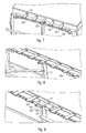
- Der erfindungsgemäße Verschlussmechanismus ist für ein erstes Ausführungsbeispiel in den
Fig. 3 - Fig. 6 und für ein zweites Ausführungsbeispiel in denFig. 7 - Fig. 9 dargestellt, und wird nachfolgend im Detail beschrieben. - Ein Ausschnitt der Messkammer 101, der Hilfsrahmen 103, das Scharnier 111 sowie ein Führungssystem 104 mit Kulissenscheibe 120 als Koppelelement 107 und der Drehbügel 112 sind in Draufsicht dargestellt.
Fig. 3 zeigt die geschlossene Tür mit dem nach links geklappten Drehbügel 112. Der erste bzw. zweite Schienenabschnitt 106, 108 weist Löcher 130 auf, in die Stifte der Schienenhalterung 115 eingreifen und die Schienenabschnitte 106, 108 somit führen und tragen. Im Endbereich des ersten bzw. zweiten Schienenabschnitts 106, 108 ist jeweils ein Schrägschlitz 110 ausgebildet. Ein Führungszapfen 104 durchgreift jeweils einen Schrägschlitz 110. Im geschlossenen Zustand der Tür 11 befindet sich der Führungszapfen 104 am der Öffnung des Schrägschlitzes gegenüberliegenden Ende. Die Kulissenscheibe 120 befindet sich in der Mitte zwischen dem ersten und zweiten Schienenabschnitt 106, 108, wobei jeweils ein Kulissenstein 123 am ersten bzw. zweiten Schienenabschnitt 106, 108 in einen Kulissenschlitz 121 der Kulissenscheibe 120 eingeführt ist. - Wird der Drehbügel 112, der in diesem Ausführungsbeispiel an den gegenüberliegenden Kulissenscheiben 120, 120' befestigt ist, wie in
Fig. 4 dargestellt, aus seiner Ruheposition ausgeschwenkt, laufen die Kulissensteine 123 entlang den geschwungenen Kulissenschlitzen 121 radial nach außen. Der erste bzw. zweite Schienenabschnitt bewegt sich jeweils in Richtung des Pfeils 125 nach außen. Der Führungszapfen 104 wird dabei in Richtung des Pfeils 126 senkrecht zur Türebene nach außen geführt. -
Fig. 5 zeigt den Verschlussmechanismus am Ende der linearen Phase. Der Führungszapfen 104 ist dabei am offenen Ende des Schrägschlitzes 110 angelangt, der Drehbügel 112 um nahezu 180° auf die andere Seite der Tür 11 geschwenkt. -
Fig. 6 zeigt nun den Verschlussmechanismus in der Rotationsphase. Über einen nicht dargestellten Griff auf der rechten Seite wird die Tür 11 einschließlich Hilfsrahmen 103 um das Scharnier 111 in Pfeilrichtung 127 gedreht. Auf der Innenseite der Tür 11 angebrachtes Absorbermaterial 129 wird sichtbar. - Die
Fig. 7 - 9 zeigen ein zweites Ausführungsbeispiel des erfindungsgemäßen Verschlussmechanismus. Dieses unterscheidet sich lediglich durch die Ausführung des ersten und zweiten Führungssystems 109, 114 vom ersten Ausführungsbeispiel. Die Tür 11, der Hilfsrahmen 103 sowie dessen Aufhängung durch die Scharniere 111 sind in gleicher Weise ausgeführt wie im ersten Ausführungsbeispiel. - Oberhalb und unterhalb der Tür 11 ist am Türrahmen 12 jeweils ein Führungssystem mittels Schienenhalterungen 115 befestigt. Der erste und zweite Schienenabschnitt ist als Gestängeabschnitt 150, 151 ausgeführt. Um die Gewichtsverteilung der Messkammer auszugleichen und das erste und zweite Führungssystem 109, 114 leicht zu halten, sind die Gestängeabschnitte 150, 151 als stabile, schmale, aus leichtem Material gefertigte Stangen ausgeführt. Die Gestängeabschnitte 150, 151 werden durch die Schienenhalterungen 115 und daran befestigte Führungselemente 154 geführt. Der Endbereich 105 eines jeden Gestängeabschnittes 150, 151 weist wiederrum einen Schrägschlitz 110 auf, in dem der Führungszapfen 104 geführt wird. Als Koppelelement wird ein Spreizgelenk 152 verwendet, das mittels Stiften 155 mit den beiden Gestängeabschnitten 150, 151 beweglich verbunden ist.
- Das Spreizgelenk 152 besteht aus zwei L-förmigen Gelenkarmen 156, 157, die beweglich mit einem Mittelelement 158 verbunden sind. Das Mittelelement 158 ist Doppel-L-förmig ausgebildet, wobei die beiden L-förmigen Komponenten um 180° um die Mitte des kürzeren Schenkels gedreht angeordnet sind. Das Mittelelement 158 ist in der Mitte des kurzen Schenkels einerseits mit einer Schienenhalterung 115 drehbar, andererseits mit der Verbindungsstange 113 fest verbunden.
- Zum Öffnen der Tür 11 wird der Drehbügel 112 in einer kreisförmigen Bewegung zur anderen Seite geschwenkt und dabei die Verbindungsstange und das daran befestigte Mittelelement 158 gedreht. Die an den langen Schenkeln des Mittelelements 158 drehbar über Stifte 155 angelenkten Gelenkarme 156, 157 werden dabei aufgespreizt und schieben die am Ende des kurzen Schenkels des ersten und zweiten Gelenkarms 156, 157 angelenkten ersten und zweiten Gestängeabschnitte 150, 151 nach außen. Der Führungszapfen 104 wird dabei wiederrum im Schrägschlitz 110 in Richtung senkrecht zur Tür vom Türrahmen 12 weg bewegt. Die Tür 11 bzw. der Türfalz 14 wird dabei aus der Nut im Türrahmen 12 senkrecht zur Türebene gleitend im Hilfsrahmen 103 herausgezogen. Sobald der Führungszapfen 104 das offene Ende des Schrägschlitzes 104 erreicht hat, kann die Tür über einen nicht dargestellten Griff um das Scharnier 111 geschwenkt werden.
- Die vorliegende Erfindung beschränkt sich nicht auf die beiden aufgezeigten Ausführungsbeispiele. So können die Führungssysteme 109, 114 auch an den Seiten der Tür 11 am Türrahmen 12 befestigt sein und die Tür 11 nach oben bzw. nach unten ausgeschwenkt werden. In gleicher Weise ist in den beschriebenen Ausführungsbeispielen ein Öffnen der Tür 11 mit Rechtsanschlag möglich, indem die Scharniere 111 anstatt an der linken Seitenwand an der rechten Seitenwand befestigt werden. Ebenso kann der Drehbügel 112 durch einen Hebelgriff, der die Verbindungsstange 113 mittels Zahnräder dreht, ersetzt werden. Ein solcher Hebelgriff kann gleichzeitig zum Schwenken der Tür verwendet werden.
- Um ein versehentliches Öffnen der Tür zu vermeiden, kann eine Arretiervorrichtung für den Drehbügel bzw. eine Hebelgriff vorgesehen werden. Ein Drehgriff kann z.B. in eine Klemmhalterung eingerastet und somit arretiert werden. Ein Hebelgriff kann beispielsweise durch ein Schloss verdrehsicher festgestellt werden.
- Anstatt ein herkömmliches Scharnier 111 an einem Hilfsrahmen 103 zu befestigen, kann ein Spezialscharnier 200 direkt an der Tür 11 befestigt werden. Wie in
Fig. 10 dargestellt, besteht das Spezialscharnier 200 aus einem Scharnierarm 201, der mit der Tür 11 und einer Scharnierplatte 202, die mit der Seitenwand 116 der Messkammer 101 fest verbunden ist. Am Scharnierarm 201 sind zwei Scharnierzapfen 204, 206 ausgebildet, wobei ein erster Scharnierzapfen 204 in einen Längsschlitz 205 und ein zweiter Scharnierzapfen 206 in einen Drehschlitz 203 eingreift. Der Drehschlitz 203 ist aus einem Längsabschnitt 208 und einem anschließenden Bogenabschnitt 207 ausgebildet. Der Längsschlitz 205 und der Längsabschnitt 208 des Drehschlitzes 203 sind gleich lang und legen die maximale Auslenkung der Tür durch die lineare Bewegung senkrecht zur Türebene fest. Der Bogenabschnitt 207 ist als ein Kreissegment geformt, dessen überstreichender Winkel den Öffnungswinkel des Spezialscharniers 200 festlegt. Das dem Bogenabschnitt 207 zugewandte Ende des Längsschlitzes 205 bildet den Mittelpunkt des Kreissegments. - Durch einen nicht dargestellten Querbügel, der über die gesamte Türbreite reicht und an der Tür 11 befestigt ist, wird die verschlossene Tür 11 senkrecht zur Türebene nach vorne aus der Nut im Türrahmen gezogen, bis die Scharnierzapfen das Ende des Längsschlitzes 205 bzw. des Längsabschnitts 208 des Drehschlitzes 203 erreichen. Danach wird durch eine Bewegung im Bogenabschnitt 207 die Tür geschwenkt. Das Spezialscharnier 200 ist dabei so ausgerichtet, dass die Scharnierplatte 202 parallel zur Rotationsebene der Tür liegt.
- Alle Elemente des erfindungsgemäßen Verschlussmechanismus, wie z.B. der zumindest eine Führungszapfen 104, das Führungssystem 109, 114 sowie die Scharniere 111, 200, sind außerhalb des abgeschirmten Bereichs und ohne Durchführung in den abgeschirmten Bereich der Messkammer hinein an der Tür 11 bzw. Hilfsrahmen 103 und der Seitenwand 116 der Messkammer 101 angebracht. Die genannten Elemente sind beispielsweise durch Schweißen, Löten oder durch Schrauben, die nicht die Messkammerwand durchdringen, befestigt. Somit sind weder zusätzliche elektromagnetische Abdichtungen notwendig, noch wird das elektromagnetische Feld im Inneren der Messkammer beeinflusst.
Claims (13)
- Verschlussmechanismus für eine elektromagnetisch abgedichtete Messeinrichtung (100) mit einer Messkammer (101), einer Tür (11) zum Schließen der Messkammer (101) sowie einer elektromagnetischen Dichtung (13), wobei die Tür (11) umfänglich mindestens einen Falz (14) aufweist, der in mindestens eine Nut (15) im Türrahmen (12) eingreift,
dadurch gekennzeichnet,
dass die Tür (11) so angebracht ist, dass sie zuerst linear (16) von der Messkammer (101) wegbewegbar und danach in einer Rotationsbewegung (17) schwenkbar ist, sodass die Tür (11) in einer linearen Bewegung ausschließlich senkrecht zur Türebene aus der Nut (15) herausgeführt wird. - Verschlussmechanismus gemäß Anspruch 1,
dadurch gekennzeichnet,
dass die elektromagnetische Dichtung (13) in mindestens einer umfänglichen Nut (15) im Türrahmen (12) der Messkammer (101) angebracht ist. - Verschlussmechanismus gemäß Anspruch 1 oder 2,
dadurch gekennzeichnet,
dass zumindest ein Führungszapfen (104) mit der Tür (11) form- oder stoffschlüssig verbunden ist. - Verschlussmechanismus gemäß einem der Ansprüche 1 bis 3,
dadurch gekennzeichnet,
dass die Tür (11) in einen Hilfsrahmen (103) eingebaut und die Tür (11) senkrecht zur Ebene der geschlossenen Tür (11) im Hilfsrahmen (103) bewegbar ist. - Verschlussmechanismus gemäß Anspruch 4,
dadurch gekennzeichnet,
dass der Hilfsrahmen (103) durch mehrere Drehscharniere (111) mit einer Seitenwand (116) der Messkammer (101) schwenkbar verbunden ist. - Verschlussmechanismus gemäß einem der Ansprüche 1 bis 5,
dadurch gekennzeichnet,
dass oberhalb und/oder unterhalb der Tür (11) ein erstes und ein zweites Führungssystem (109, 114) an der Messkammer (101) angebracht ist. - Verschlussmechanismus gemäß Anspruch 6,
dadurch gekennzeichnet,
dass ein Führungssystem (109, 114) mindestens zwei Schienenabschnitte (106, 108) umfasst, die an einem Ende über ein Koppelelement (107) beweglich miteinander verbunden sind, und
dass die Schienenabschnitte (106, 108) am jeweils entgegengesetzten Endbereich (105) einen Schrägschlitz (110) aufweisen. - Verschlussmechanismus gemäß Anspruch 7,
dadurch gekennzeichnet,
dass das Koppelelement (107) beweglich gelagert ist und die Bewegung des Koppelelements (107) die mindestens zwei Schienenabschnitte (106, 108) parallel zur Tür (11) nach außen (125) führt. - Verschlussmechanismus gemäß Anspruch 7 oder 8,
dadurch gekennzeichnet,
dass mehrere Führungszapfen (104) in jeweils einen Schrägschlitz (110) im Führungssystem (109, 114) eingreifen und im Führungssystem (109, 114) linear in Richtung senkrecht (126) zur Tür (11) geführt sind. - Verschlussmechanismus gemäß einem der Ansprüche 1 bis 9,
dadurch gekennzeichnet,
dass die Tür durch die lineare Bewegung zwischen 1 cm und 5 cm, bevorzugt zwischen 2 cm und 3 cm verschoben wird. - Verschlussmechanismus gemäß einem der Ansprüche 1 bis 10,
dadurch gekennzeichnet,
dass die elektromagnetische Dichtung (13) als metallische Feder ausgebildet ist. - Verschlussmechanismus gemäß einem der Ansprüche 1 bis 2,
dadurch gekennzeichnet,
dass ein Spezialscharnier (200), bestehend aus einer Scharnierplatte (202) und einem Scharnierarm (201), die Tür (11) mit einer Seitenwand (116) der Messeinrichtung (100) verbindet. - Verschlussmechanismus gemäß Anspruch 12,
dadurch gekennzeichnet,
dass die Scharnierplatte einen Längsschlitz (205) und einen Drehschlitz (203) aufweist, in denen Scharnierzapfen (204, 206) des Scharnierarms (201) geführt sind, wobei der Drehschlitz (203) aus einem Längsabschnitt (208) und einem Bogenabschnitt (207) besteht.
Applications Claiming Priority (2)
| Application Number | Priority Date | Filing Date | Title |
|---|---|---|---|
| DE102009038916A DE102009038916A1 (de) | 2009-08-26 | 2009-08-26 | Verschlussmechanismus für eine Messeinrichtung |
| PCT/EP2010/005024 WO2011023314A1 (de) | 2009-08-26 | 2010-08-16 | Elektromagnetisch dichte tür für eine messkammer |
Publications (2)
| Publication Number | Publication Date |
|---|---|
| EP2470740A1 EP2470740A1 (de) | 2012-07-04 |
| EP2470740B1 true EP2470740B1 (de) | 2015-10-07 |
Family
ID=42937285
Family Applications (1)
| Application Number | Title | Priority Date | Filing Date |
|---|---|---|---|
| EP10745560.2A Active EP2470740B1 (de) | 2009-08-26 | 2010-08-16 | Elektromagnetisch dichte Tür für eine Messkammer |
Country Status (4)
| Country | Link |
|---|---|
| US (1) | US9574391B2 (de) |
| EP (1) | EP2470740B1 (de) |
| DE (1) | DE102009038916A1 (de) |
| WO (1) | WO2011023314A1 (de) |
Cited By (1)
| Publication number | Priority date | Publication date | Assignee | Title |
|---|---|---|---|---|
| CN110242182A (zh) * | 2019-05-28 | 2019-09-17 | 南宁学院 | 财务专用电磁屏蔽门 |
Families Citing this family (6)
| Publication number | Priority date | Publication date | Assignee | Title |
|---|---|---|---|---|
| US9909354B1 (en) * | 2012-08-17 | 2018-03-06 | Michael Wayne Kirkpatrick | Door apparatus with boom assembly |
| CN103412098B (zh) * | 2013-08-30 | 2015-11-04 | 昆山市创新科技检测仪器有限公司 | 一种具有新型密封结构的试验舱 |
| EP3262261B1 (de) * | 2015-02-26 | 2020-09-16 | Huawei Technologies Co. Ltd. | Tür- und aufhängungsmechanismusanordnung und eine anordnung aus einem länglichen gehäuse und einer tür- und aufhängungsmechanismusanordnung |
| SE1650291A1 (en) * | 2016-03-04 | 2017-09-05 | Hans-Erik Johansson I Hagstad Ab | Lockable electronics cabinet |
| CN114893100B (zh) * | 2022-06-15 | 2022-09-23 | 沈阳和研科技有限公司 | 一种应用于划片机的旋转滑门 |
| EP4412415A1 (de) * | 2023-01-25 | 2024-08-07 | Hans-Erik Johansson I Hagstad AB | Elektromagnetisch abgeschirmter elektronikschrank |
Family Cites Families (24)
| Publication number | Priority date | Publication date | Assignee | Title |
|---|---|---|---|---|
| US529171A (en) * | 1894-11-13 | Scheidt | ||
| US116686A (en) * | 1871-07-04 | Improvement in safe-doors | ||
| US82658A (en) * | 1868-09-29 | Philip j | ||
| US3256384A (en) * | 1962-02-12 | 1966-06-14 | Erik A Lindgren | Sliding door for a shielding enclosure |
| US3531577A (en) * | 1968-07-10 | 1970-09-29 | Sprague Electric Co | Door for a shielded enclosure |
| US3768203A (en) * | 1972-01-26 | 1973-10-30 | Amsco Ind Co | Closure operating structure |
| US3788689A (en) * | 1972-10-24 | 1974-01-29 | R Lloyd | Door locking means |
| US3981054A (en) * | 1975-07-18 | 1976-09-21 | Johnson Sheet Metal Works Corporation | Burial casket with improved sealing system |
| US4262447A (en) * | 1979-08-20 | 1981-04-21 | Sybron Corporation | Double acting hinged pressure vessel closure |
| CH651354A5 (en) * | 1980-08-27 | 1985-09-13 | Winkler & Cie Ag Elektro | Door arrangement for an electromagnetically shielded room |
| FI63992C (fi) * | 1982-05-28 | 1983-09-12 | Euramecano Ab Oy | Doerr i en konstruktion som foerhindrar oevergaong av stoerningsfaelt |
| DE3907181A1 (de) * | 1989-01-23 | 1990-08-16 | Kunz Alfred & Co | Geschirmte tuer mit tuerrahmen fuer abgeschirmte raeume |
| US4932160A (en) * | 1989-05-04 | 1990-06-12 | Sterilizer Technologies Corporation | Closure apparatus and method |
| DE3916836C1 (en) * | 1989-05-19 | 1990-03-15 | Abs Allgemeiner Brandschutz G. U. M. Breivogel Gmbh, 6500 Mainz, De | Actuating mechanism for sealing door esp. for EM screening - has rotating shaft with connecting lever closing door against stop-bands on door frame |
| DE3919184A1 (de) | 1989-06-12 | 1990-12-13 | Siemens Ag | Begehbare abschirmkammer fuer biomagnetische messeinrichtungen |
| US5199369A (en) * | 1991-03-14 | 1993-04-06 | Westinghouse Electric Corp. | Water tight door |
| DE9105731U1 (de) * | 1991-05-08 | 1991-08-01 | Nukem GmbH, 63755 Alzenau | Behältnis, insbesondere Kleincontainer quaderförmiger Geometrie |
| US5223670A (en) * | 1991-12-02 | 1993-06-29 | Her Majesty The Queen In Right Of Canada | Hinged door assembly |
| DE9214897U1 (de) * | 1992-11-02 | 1993-03-04 | Liebherr-Hausgeräte GmbH, 7955 Ochsenhausen | Kühl- und/oder Gefrierschrank |
| FI110155B (fi) * | 1994-12-27 | 2002-11-29 | Euroshield Oy | Magneettisesti suojatun huoneen ovirakenne |
| US6412221B1 (en) * | 1999-08-02 | 2002-07-02 | Thermal Engineering International | Catalyst door system |
| US7090263B2 (en) * | 2001-05-04 | 2006-08-15 | Spx Corporation | Door latching device and method |
| DE60336491D1 (de) * | 2002-10-09 | 2011-05-05 | Lokaway Pty Ltd | Sicherheitstür- und rahmenkonstruktion |
| WO2004090270A2 (de) | 2003-04-09 | 2004-10-21 | Boffi S.P.A. | Beschlag |
-
2009
- 2009-08-26 DE DE102009038916A patent/DE102009038916A1/de not_active Withdrawn
-
2010
- 2010-08-16 US US13/392,499 patent/US9574391B2/en active Active
- 2010-08-16 WO PCT/EP2010/005024 patent/WO2011023314A1/de not_active Ceased
- 2010-08-16 EP EP10745560.2A patent/EP2470740B1/de active Active
Cited By (1)
| Publication number | Priority date | Publication date | Assignee | Title |
|---|---|---|---|---|
| CN110242182A (zh) * | 2019-05-28 | 2019-09-17 | 南宁学院 | 财务专用电磁屏蔽门 |
Also Published As
| Publication number | Publication date |
|---|---|
| DE102009038916A1 (de) | 2011-03-03 |
| US9574391B2 (en) | 2017-02-21 |
| WO2011023314A1 (de) | 2011-03-03 |
| US20120153790A1 (en) | 2012-06-21 |
| EP2470740A1 (de) | 2012-07-04 |
Similar Documents
| Publication | Publication Date | Title |
|---|---|---|
| WO2011023314A1 (de) | Elektromagnetisch dichte tür für eine messkammer | |
| DE3828288C1 (de) | ||
| DE69501943T2 (de) | Struktur einer Tür eines magnetisch abgeschirmten Raumes | |
| EP3339541B1 (de) | Faltanlage | |
| DE4019569C2 (de) | Sektionaltor | |
| EP0947654A1 (de) | Verschwindscharnier | |
| WO2022020867A1 (de) | Scharnier | |
| DE4320322A1 (de) | Scharniereinrichtung für ein Dachflächenfenster | |
| DE19604879C1 (de) | Doppelgelenk-Scharnier für eine Rückwand-Tür eines Lastfahrzeug-Aufbaus | |
| DE2517367A1 (de) | Beschlag fuer kipp-schwenkfluegel von fenstern, tueren o. dgl. | |
| EP1678402B1 (de) | Vorrichtung zur aufnahme des gewichtes einer ein- oder zweiflügeligen tür für einen schaltschrank | |
| DE102017212714B3 (de) | Gelenkband für ein Trennelement | |
| DE102012104852A1 (de) | Führungsschienenanordnung | |
| DE102008012274A1 (de) | Trennwand mit Gelenkband und Gelenkband für eine Trennwand | |
| DE202005003872U1 (de) | Führungssystem zum Führen von Schiebetüren oder Schiebefenstern | |
| EP2722472B1 (de) | Drehflügelbeschlag und Duschabtrennung | |
| EP2740872B1 (de) | Zur verdeckten anordnung vorgesehenes ecklager | |
| DE102010000675A1 (de) | Ecklager eines gegen einen Rahmen schwenkbaren Flügels eines Fensters und Fenster mit einem solchen Ecklager | |
| EP0379898B1 (de) | Geschirmte Tür mit Türrahmen für abgeschirmte Räume | |
| DE102021115490A1 (de) | Feststellvorrichtung für beidseitig angeschlagene Tür | |
| EP0258766B1 (de) | Scharnier für Selbstkassierergehäuse | |
| DE19832356C2 (de) | Kantenriegelbeschlag | |
| EP2933416B1 (de) | Türantrieb | |
| DE10301046A1 (de) | Drehbeschlag für die verdeckte Anordnung an Türen oder Fenstern | |
| DE102012107443B4 (de) | Vorrichtung für das Steuern der Schließfolge von zweiflügeligen Schwenktüren, welche mit Gleitschienenschließern ausgestattet sind |
Legal Events
| Date | Code | Title | Description |
|---|---|---|---|
| PUAI | Public reference made under article 153(3) epc to a published international application that has entered the european phase |
Free format text: ORIGINAL CODE: 0009012 |
|
| 17P | Request for examination filed |
Effective date: 20110805 |
|
| AK | Designated contracting states |
Kind code of ref document: A1 Designated state(s): AL AT BE BG CH CY CZ DE DK EE ES FI FR GB GR HR HU IE IS IT LI LT LU LV MC MK MT NL NO PL PT RO SE SI SK SM TR |
|
| DAX | Request for extension of the european patent (deleted) | ||
| GRAP | Despatch of communication of intention to grant a patent |
Free format text: ORIGINAL CODE: EPIDOSNIGR1 |
|
| INTG | Intention to grant announced |
Effective date: 20150512 |
|
| GRAS | Grant fee paid |
Free format text: ORIGINAL CODE: EPIDOSNIGR3 |
|
| GRAA | (expected) grant |
Free format text: ORIGINAL CODE: 0009210 |
|
| AK | Designated contracting states |
Kind code of ref document: B1 Designated state(s): AL AT BE BG CH CY CZ DE DK EE ES FI FR GB GR HR HU IE IS IT LI LT LU LV MC MK MT NL NO PL PT RO SE SI SK SM TR |
|
| REG | Reference to a national code |
Ref country code: GB Ref legal event code: FG4D Free format text: NOT ENGLISH |
|
| REG | Reference to a national code |
Ref country code: AT Ref legal event code: REF Ref document number: 753875 Country of ref document: AT Kind code of ref document: T Effective date: 20151015 Ref country code: CH Ref legal event code: EP |
|
| REG | Reference to a national code |
Ref country code: IE Ref legal event code: FG4D Free format text: LANGUAGE OF EP DOCUMENT: GERMAN |
|
| REG | Reference to a national code |
Ref country code: DE Ref legal event code: R096 Ref document number: 502010010422 Country of ref document: DE |
|
| REG | Reference to a national code |
Ref country code: NL Ref legal event code: MP Effective date: 20151007 |
|
| REG | Reference to a national code |
Ref country code: LT Ref legal event code: MG4D |
|
| PG25 | Lapsed in a contracting state [announced via postgrant information from national office to epo] |
Ref country code: ES Free format text: LAPSE BECAUSE OF FAILURE TO SUBMIT A TRANSLATION OF THE DESCRIPTION OR TO PAY THE FEE WITHIN THE PRESCRIBED TIME-LIMIT Effective date: 20151007 Ref country code: IT Free format text: LAPSE BECAUSE OF FAILURE TO SUBMIT A TRANSLATION OF THE DESCRIPTION OR TO PAY THE FEE WITHIN THE PRESCRIBED TIME-LIMIT Effective date: 20151007 Ref country code: NO Free format text: LAPSE BECAUSE OF FAILURE TO SUBMIT A TRANSLATION OF THE DESCRIPTION OR TO PAY THE FEE WITHIN THE PRESCRIBED TIME-LIMIT Effective date: 20160107 Ref country code: IS Free format text: LAPSE BECAUSE OF FAILURE TO SUBMIT A TRANSLATION OF THE DESCRIPTION OR TO PAY THE FEE WITHIN THE PRESCRIBED TIME-LIMIT Effective date: 20160207 Ref country code: NL Free format text: LAPSE BECAUSE OF FAILURE TO SUBMIT A TRANSLATION OF THE DESCRIPTION OR TO PAY THE FEE WITHIN THE PRESCRIBED TIME-LIMIT Effective date: 20151007 Ref country code: LT Free format text: LAPSE BECAUSE OF FAILURE TO SUBMIT A TRANSLATION OF THE DESCRIPTION OR TO PAY THE FEE WITHIN THE PRESCRIBED TIME-LIMIT Effective date: 20151007 Ref country code: HR Free format text: LAPSE BECAUSE OF FAILURE TO SUBMIT A TRANSLATION OF THE DESCRIPTION OR TO PAY THE FEE WITHIN THE PRESCRIBED TIME-LIMIT Effective date: 20151007 |
|
| PG25 | Lapsed in a contracting state [announced via postgrant information from national office to epo] |
Ref country code: PT Free format text: LAPSE BECAUSE OF FAILURE TO SUBMIT A TRANSLATION OF THE DESCRIPTION OR TO PAY THE FEE WITHIN THE PRESCRIBED TIME-LIMIT Effective date: 20160208 Ref country code: PL Free format text: LAPSE BECAUSE OF FAILURE TO SUBMIT A TRANSLATION OF THE DESCRIPTION OR TO PAY THE FEE WITHIN THE PRESCRIBED TIME-LIMIT Effective date: 20151007 Ref country code: GR Free format text: LAPSE BECAUSE OF FAILURE TO SUBMIT A TRANSLATION OF THE DESCRIPTION OR TO PAY THE FEE WITHIN THE PRESCRIBED TIME-LIMIT Effective date: 20160108 Ref country code: SE Free format text: LAPSE BECAUSE OF FAILURE TO SUBMIT A TRANSLATION OF THE DESCRIPTION OR TO PAY THE FEE WITHIN THE PRESCRIBED TIME-LIMIT Effective date: 20151007 Ref country code: LV Free format text: LAPSE BECAUSE OF FAILURE TO SUBMIT A TRANSLATION OF THE DESCRIPTION OR TO PAY THE FEE WITHIN THE PRESCRIBED TIME-LIMIT Effective date: 20151007 |
|
| REG | Reference to a national code |
Ref country code: DE Ref legal event code: R097 Ref document number: 502010010422 Country of ref document: DE |
|
| PG25 | Lapsed in a contracting state [announced via postgrant information from national office to epo] |
Ref country code: CZ Free format text: LAPSE BECAUSE OF FAILURE TO SUBMIT A TRANSLATION OF THE DESCRIPTION OR TO PAY THE FEE WITHIN THE PRESCRIBED TIME-LIMIT Effective date: 20151007 |
|
| PLBE | No opposition filed within time limit |
Free format text: ORIGINAL CODE: 0009261 |
|
| STAA | Information on the status of an ep patent application or granted ep patent |
Free format text: STATUS: NO OPPOSITION FILED WITHIN TIME LIMIT |
|
| PG25 | Lapsed in a contracting state [announced via postgrant information from national office to epo] |
Ref country code: RO Free format text: LAPSE BECAUSE OF FAILURE TO SUBMIT A TRANSLATION OF THE DESCRIPTION OR TO PAY THE FEE WITHIN THE PRESCRIBED TIME-LIMIT Effective date: 20151007 Ref country code: EE Free format text: LAPSE BECAUSE OF FAILURE TO SUBMIT A TRANSLATION OF THE DESCRIPTION OR TO PAY THE FEE WITHIN THE PRESCRIBED TIME-LIMIT Effective date: 20151007 Ref country code: DK Free format text: LAPSE BECAUSE OF FAILURE TO SUBMIT A TRANSLATION OF THE DESCRIPTION OR TO PAY THE FEE WITHIN THE PRESCRIBED TIME-LIMIT Effective date: 20151007 Ref country code: SM Free format text: LAPSE BECAUSE OF FAILURE TO SUBMIT A TRANSLATION OF THE DESCRIPTION OR TO PAY THE FEE WITHIN THE PRESCRIBED TIME-LIMIT Effective date: 20151007 Ref country code: SK Free format text: LAPSE BECAUSE OF FAILURE TO SUBMIT A TRANSLATION OF THE DESCRIPTION OR TO PAY THE FEE WITHIN THE PRESCRIBED TIME-LIMIT Effective date: 20151007 |
|
| 26N | No opposition filed |
Effective date: 20160708 |
|
| PG25 | Lapsed in a contracting state [announced via postgrant information from national office to epo] |
Ref country code: SI Free format text: LAPSE BECAUSE OF FAILURE TO SUBMIT A TRANSLATION OF THE DESCRIPTION OR TO PAY THE FEE WITHIN THE PRESCRIBED TIME-LIMIT Effective date: 20151007 |
|
| PG25 | Lapsed in a contracting state [announced via postgrant information from national office to epo] |
Ref country code: BE Free format text: LAPSE BECAUSE OF NON-PAYMENT OF DUE FEES Effective date: 20160831 |
|
| PG25 | Lapsed in a contracting state [announced via postgrant information from national office to epo] |
Ref country code: MC Free format text: LAPSE BECAUSE OF FAILURE TO SUBMIT A TRANSLATION OF THE DESCRIPTION OR TO PAY THE FEE WITHIN THE PRESCRIBED TIME-LIMIT Effective date: 20151007 |
|
| REG | Reference to a national code |
Ref country code: CH Ref legal event code: PL |
|
| GBPC | Gb: european patent ceased through non-payment of renewal fee |
Effective date: 20160816 |
|
| PG25 | Lapsed in a contracting state [announced via postgrant information from national office to epo] |
Ref country code: LI Free format text: LAPSE BECAUSE OF NON-PAYMENT OF DUE FEES Effective date: 20160831 Ref country code: CH Free format text: LAPSE BECAUSE OF NON-PAYMENT OF DUE FEES Effective date: 20160831 Ref country code: FI Free format text: LAPSE BECAUSE OF NON-PAYMENT OF DUE FEES Effective date: 20160816 |
|
| REG | Reference to a national code |
Ref country code: FR Ref legal event code: ST Effective date: 20170428 |
|
| REG | Reference to a national code |
Ref country code: IE Ref legal event code: MM4A |
|
| PG25 | Lapsed in a contracting state [announced via postgrant information from national office to epo] |
Ref country code: FR Free format text: LAPSE BECAUSE OF NON-PAYMENT OF DUE FEES Effective date: 20160831 Ref country code: GB Free format text: LAPSE BECAUSE OF NON-PAYMENT OF DUE FEES Effective date: 20160816 Ref country code: IE Free format text: LAPSE BECAUSE OF NON-PAYMENT OF DUE FEES Effective date: 20160816 |
|
| PG25 | Lapsed in a contracting state [announced via postgrant information from national office to epo] |
Ref country code: LU Free format text: LAPSE BECAUSE OF NON-PAYMENT OF DUE FEES Effective date: 20160816 |
|
| REG | Reference to a national code |
Ref country code: AT Ref legal event code: MM01 Ref document number: 753875 Country of ref document: AT Kind code of ref document: T Effective date: 20160816 |
|
| PG25 | Lapsed in a contracting state [announced via postgrant information from national office to epo] |
Ref country code: AT Free format text: LAPSE BECAUSE OF NON-PAYMENT OF DUE FEES Effective date: 20160816 |
|
| PG25 | Lapsed in a contracting state [announced via postgrant information from national office to epo] |
Ref country code: CY Free format text: LAPSE BECAUSE OF FAILURE TO SUBMIT A TRANSLATION OF THE DESCRIPTION OR TO PAY THE FEE WITHIN THE PRESCRIBED TIME-LIMIT Effective date: 20151007 Ref country code: HU Free format text: LAPSE BECAUSE OF FAILURE TO SUBMIT A TRANSLATION OF THE DESCRIPTION OR TO PAY THE FEE WITHIN THE PRESCRIBED TIME-LIMIT; INVALID AB INITIO Effective date: 20100816 |
|
| PG25 | Lapsed in a contracting state [announced via postgrant information from national office to epo] |
Ref country code: TR Free format text: LAPSE BECAUSE OF FAILURE TO SUBMIT A TRANSLATION OF THE DESCRIPTION OR TO PAY THE FEE WITHIN THE PRESCRIBED TIME-LIMIT Effective date: 20151007 Ref country code: MK Free format text: LAPSE BECAUSE OF FAILURE TO SUBMIT A TRANSLATION OF THE DESCRIPTION OR TO PAY THE FEE WITHIN THE PRESCRIBED TIME-LIMIT Effective date: 20151007 Ref country code: MT Free format text: LAPSE BECAUSE OF FAILURE TO SUBMIT A TRANSLATION OF THE DESCRIPTION OR TO PAY THE FEE WITHIN THE PRESCRIBED TIME-LIMIT Effective date: 20151007 |
|
| PG25 | Lapsed in a contracting state [announced via postgrant information from national office to epo] |
Ref country code: BG Free format text: LAPSE BECAUSE OF FAILURE TO SUBMIT A TRANSLATION OF THE DESCRIPTION OR TO PAY THE FEE WITHIN THE PRESCRIBED TIME-LIMIT Effective date: 20151007 |
|
| PG25 | Lapsed in a contracting state [announced via postgrant information from national office to epo] |
Ref country code: AL Free format text: LAPSE BECAUSE OF FAILURE TO SUBMIT A TRANSLATION OF THE DESCRIPTION OR TO PAY THE FEE WITHIN THE PRESCRIBED TIME-LIMIT Effective date: 20151007 |
|
| P01 | Opt-out of the competence of the unified patent court (upc) registered |
Effective date: 20230525 |
|
| PGFP | Annual fee paid to national office [announced via postgrant information from national office to epo] |
Ref country code: DE Payment date: 20250819 Year of fee payment: 16 |