EP2469504B1 - Anzeigsteuervorrichtung und Anzeigeschicht-Kombinationsprogramm - Google Patents
Anzeigsteuervorrichtung und Anzeigeschicht-Kombinationsprogramm Download PDFInfo
- Publication number
- EP2469504B1 EP2469504B1 EP11194380.9A EP11194380A EP2469504B1 EP 2469504 B1 EP2469504 B1 EP 2469504B1 EP 11194380 A EP11194380 A EP 11194380A EP 2469504 B1 EP2469504 B1 EP 2469504B1
- Authority
- EP
- European Patent Office
- Prior art keywords
- image data
- layer
- color information
- run
- upper layer
- Prior art date
- Legal status (The legal status is an assumption and is not a legal conclusion. Google has not performed a legal analysis and makes no representation as to the accuracy of the status listed.)
- Active
Links
Images


Classifications
-
- G—PHYSICS
- G09—EDUCATION; CRYPTOGRAPHY; DISPLAY; ADVERTISING; SEALS
- G09G—ARRANGEMENTS OR CIRCUITS FOR CONTROL OF INDICATING DEVICES USING STATIC MEANS TO PRESENT VARIABLE INFORMATION
- G09G5/00—Control arrangements or circuits for visual indicators common to cathode-ray tube indicators and other visual indicators
- G09G5/02—Control arrangements or circuits for visual indicators common to cathode-ray tube indicators and other visual indicators characterised by the way in which colour is displayed
- G09G5/026—Control of mixing and/or overlay of colours in general
-
- G—PHYSICS
- G01—MEASURING; TESTING
- G01C—MEASURING DISTANCES, LEVELS OR BEARINGS; SURVEYING; NAVIGATION; GYROSCOPIC INSTRUMENTS; PHOTOGRAMMETRY OR VIDEOGRAMMETRY
- G01C21/00—Navigation; Navigational instruments not provided for in groups G01C1/00 - G01C19/00
- G01C21/26—Navigation; Navigational instruments not provided for in groups G01C1/00 - G01C19/00 specially adapted for navigation in a road network
- G01C21/34—Route searching; Route guidance
- G01C21/36—Input/output arrangements for on-board computers
- G01C21/3667—Display of a road map
- G01C21/367—Details, e.g. road map scale, orientation, zooming, illumination, level of detail, scrolling of road map or positioning of current position marker
-
- G—PHYSICS
- G06—COMPUTING OR CALCULATING; COUNTING
- G06T—IMAGE DATA PROCESSING OR GENERATION, IN GENERAL
- G06T9/00—Image coding
-
- G—PHYSICS
- G09—EDUCATION; CRYPTOGRAPHY; DISPLAY; ADVERTISING; SEALS
- G09G—ARRANGEMENTS OR CIRCUITS FOR CONTROL OF INDICATING DEVICES USING STATIC MEANS TO PRESENT VARIABLE INFORMATION
- G09G5/00—Control arrangements or circuits for visual indicators common to cathode-ray tube indicators and other visual indicators
- G09G5/36—Control arrangements or circuits for visual indicators common to cathode-ray tube indicators and other visual indicators characterised by the display of a graphic pattern, e.g. using an all-points-addressable [APA] memory
- G09G5/39—Control of the bit-mapped memory
- G09G5/393—Arrangements for updating the contents of the bit-mapped memory
-
- H—ELECTRICITY
- H04—ELECTRIC COMMUNICATION TECHNIQUE
- H04N—PICTORIAL COMMUNICATION, e.g. TELEVISION
- H04N5/00—Details of television systems
- H04N5/222—Studio circuitry; Studio devices; Studio equipment
- H04N5/262—Studio circuits, e.g. for mixing, switching-over, change of character of image, other special effects ; Cameras specially adapted for the electronic generation of special effects
- H04N5/272—Means for inserting a foreground image in a background image, i.e. inlay, outlay
-
- H—ELECTRICITY
- H04—ELECTRIC COMMUNICATION TECHNIQUE
- H04N—PICTORIAL COMMUNICATION, e.g. TELEVISION
- H04N9/00—Details of colour television systems
- H04N9/64—Circuits for processing colour signals
- H04N9/74—Circuits for processing colour signals for obtaining special effects
- H04N9/76—Circuits for processing colour signals for obtaining special effects for mixing of colour signals
-
- G—PHYSICS
- G09—EDUCATION; CRYPTOGRAPHY; DISPLAY; ADVERTISING; SEALS
- G09G—ARRANGEMENTS OR CIRCUITS FOR CONTROL OF INDICATING DEVICES USING STATIC MEANS TO PRESENT VARIABLE INFORMATION
- G09G2320/00—Control of display operating conditions
- G09G2320/02—Improving the quality of display appearance
- G09G2320/0252—Improving the response speed
-
- G—PHYSICS
- G09—EDUCATION; CRYPTOGRAPHY; DISPLAY; ADVERTISING; SEALS
- G09G—ARRANGEMENTS OR CIRCUITS FOR CONTROL OF INDICATING DEVICES USING STATIC MEANS TO PRESENT VARIABLE INFORMATION
- G09G2340/00—Aspects of display data processing
- G09G2340/02—Handling of images in compressed format, e.g. JPEG, MPEG
-
- G—PHYSICS
- G09—EDUCATION; CRYPTOGRAPHY; DISPLAY; ADVERTISING; SEALS
- G09G—ARRANGEMENTS OR CIRCUITS FOR CONTROL OF INDICATING DEVICES USING STATIC MEANS TO PRESENT VARIABLE INFORMATION
- G09G2340/00—Aspects of display data processing
- G09G2340/12—Overlay of images, i.e. displayed pixel being the result of switching between the corresponding input pixels
-
- G—PHYSICS
- G09—EDUCATION; CRYPTOGRAPHY; DISPLAY; ADVERTISING; SEALS
- G09G—ARRANGEMENTS OR CIRCUITS FOR CONTROL OF INDICATING DEVICES USING STATIC MEANS TO PRESENT VARIABLE INFORMATION
- G09G2350/00—Solving problems of bandwidth in display systems
-
- G—PHYSICS
- G09—EDUCATION; CRYPTOGRAPHY; DISPLAY; ADVERTISING; SEALS
- G09G—ARRANGEMENTS OR CIRCUITS FOR CONTROL OF INDICATING DEVICES USING STATIC MEANS TO PRESENT VARIABLE INFORMATION
- G09G5/00—Control arrangements or circuits for visual indicators common to cathode-ray tube indicators and other visual indicators
- G09G5/36—Control arrangements or circuits for visual indicators common to cathode-ray tube indicators and other visual indicators characterised by the display of a graphic pattern, e.g. using an all-points-addressable [APA] memory
- G09G5/39—Control of the bit-mapped memory
- G09G5/395—Arrangements specially adapted for transferring the contents of the bit-mapped memory to the screen
- G09G5/397—Arrangements specially adapted for transferring the contents of two or more bit-mapped memories to the screen simultaneously, e.g. for mixing or overlay
Definitions
- the present invention relates to a display control device and to a display layer combination program.
- Japanese Laid-Open Patent Publication 2008-305030 a combined image generation device is disclosed in which, when a plurality of display layers are to be combined, a decision is made for each pixel as to whether or not the upper display layer is colored as transparent, and superimposition processing is only performed for those pixels that are not colored as transparent.
- the object of the present invention is to provide a display control device that implements a combination processing method that can efficiently skip over pixels that are colored as transparent, thus combining a plurality of display layers at high speed.
- a display control device displays, upon a display device, combined image data obtained by combining image data for a plurality of display layers.
- Each of the plurality of display layers consists of a plurality of pixels, and the image data of each of the plurality of display layers includes color information relating to the colors of the plurality of pixels included in the display layer.
- the display control device includes: a transparent color information storage unit that stores transparent color information specifying color information for a transparent color in the image data for each of the plurality of display layers, except for the lowermost display layer; a run-length counter that calculates a run-length specifying, for the color information included in the image data for each of the plurality of display layers except for the lowermost display layer, the number of consecutive pixels having the same color information; a combination calculation unit that combines the image data for the plurality of display layers to generate the combined image data; and/or a combined image display unit that outputs the combined image data generated by the combination calculation unit to the display device to display the combined image upon the display device.
- the combination calculation unit performs combination by ignoring the image data for the total number run-length of consecutive pixels.
- the display control device of the first aspect may further include: an upper layer update decision unit that, for each of the one or more upper layers among the plurality of display layers other than the lowermost display layer, decides whether or not the image data for that upper layer has been updated; a lower layer update decision unit that decides whether or not the image data for the lowermost layer among the plurality of display layers has been updated; a compression unit that generates compressed image data based upon the color information and upon the run-length of that color information calculated by the run-length counter, included in the image data for each of the one or more upper layers, and stores the compressed image data in one or more compressed layers each corresponding to the one or more upper layers; and a decompression unit that reads out, from the compressed image data stored in each of the compressed layers, the color information and the run-length of that color information.
- an upper layer update decision unit that, for each of the one or more upper layers among the plurality of display layers other than the lowermost display layer, decides whether or not the image data for that upper layer has been updated
- the combination calculation unit generates the combined image data by successively combining the image data for the one or more upper layers with the image data for the lowermost layer, in increasing hierarchical order from the upper layer of lowest order; for each upper layer, among the one or more upper layers, for which it has been decided by the upper layer update decision unit that the image data has been updated, combines the image data for that upper layer with the image data for the lowermost layer on the basis of the run-length calculated by the run-length counter when the compression unit generates the compressed image data for the image data; and, for each upper layer, among the one or more upper layers, for which it has not been decided by the upper layer update decision unit that the image data has been updated, when it has been decided that the image data of the lowermost layer has been updated, combines the image data for that upper layer with the image data for the lowermost layer on the basis of the color information and the run-length read out by the decompression unit from the compressed image data stored in correspondence to that upper layer.
- the display control device of the second aspect may further include an image update frequency decision unit that makes a decision as to whether or not the image data for each of the one or more upper layers is being updated more frequently than a predetermined frame rate.
- an image update frequency decision unit that makes a decision as to whether or not the image data for each of the one or more upper layers is being updated more frequently than a predetermined frame rate.
- a display layer combination program is for causing a CPU to combine image data for a plurality of display layers stored in a memory.
- each of the plurality of display layers consists of a plurality of pixels; the image data for each of the plurality of display layers includes color information relating to the colors of the plurality of pixels included in that display layer; and transparent color information specifying color information for a transparent color in the image data for each of the plurality of display layers, except for the lowermost display layer, is stored in the memory.
- the program may cause the CPU to function as: a run-length calculation unit that calculates a run-length specifying, for the color information included in the image data for each of the plurality of display layers except for the lowermost display layer, the number of consecutive pixels having the same color information; and a combination calculation unit that combines the image data for the plurality of display layers by units of pixels to generate the combined image data. If, for some display layer among the plurality of display layers other than the lowermost layer, the color information for a total of run-length pixels calculated by the run-length counter is a transparent color, the combination calculation unit performs combination by ignoring the image data for the total number run-length of consecutive pixels.
- the program may further cause the CPU to function as: an upper layer update decision unit that, for each of the one or more upper layers among the plurality of display layers other than the lowermost display layer, decides whether or not the image data for that upper layer has been updated; a lower layer update decision unit that decides whether or not the image data for the lowermost layer among the plurality of display layers has been updated; a compression unit that generates compressed image data based upon color information and the run-length of that color information calculated by the run-length counter, included in the image data for each of the one or more upper layers, and stores the compressed image data in one or more compressed layers each corresponding to the one or more upper layers; and a decompression unit that reads out, from the compressed image data stored in each of the compressed layers, the color information and the run-length of that color information.
- the combination calculation unit generates the combined image data by successively combining the image data for the one or more upper layers with the image data for the lowermost layer, in increasing hierarchical order from the upper layer of lowest order; for each upper layer, among the one or more upper layers, for which it has been decided by the upper layer update decision unit that the image data has been updated, combines the image data for that upper layer with the image data for the lowermost layer on the basis of the run-length calculated by the run-length counter when the compression unit generates the compressed image data for the image data; and for each upper layer, among the one or more upper layers, for which it has not been decided by the upper layer update decision unit that the image data has been updated, when it has been decided that the image data of the lowermost layer has been updated, combines the image data for that upper layer with the image data for the lowermost layer on the basis of the color information and the run-length read out by the decompression unit from the compressed image data stored in correspondence to that upper layer.
- the display control device of the present invention it is possible efficiently to skip over pixels that are colored as transparent, thus combining a plurality of display layers at high speed.
- the display control device according to the present invention can be applied to a navigation device or the like.
- a navigation device or the like.
- Fig. 1 is a schematic figure for explanation of processing performed by the navigation device for combining images on two display layers.
- a plurality of display layers to be combined during the operation of the navigation device an upper layer 300 and a lower layer 400 are shown.
- a surroundings map 410 of the area surrounding the position of the subject vehicle to which this navigation device is mounted is shown.
- an image drawn in the upper layer 300 an image that is to be overlaid upon the surroundings map 410 drawn in the lower layer 400 is shown, containing a map mark 310 that indicates the scale of the surroundings map 410 and its orientation and so on, and a subject vehicle position mark 320 that indicates the position of the subject vehicle and so on.
- the image drawn in the upper layer 300 is superimposed by the navigation device upon the image drawn in the lower layer 400, so as to obtain a combined image 610.
- the combined image 610 is also updated.
- Each of the image in the upper layer 300, the image in the lower layer 400, and the combined image 610 in Fig. 1 is stored by the navigation device in the state of being divided into a plurality of pixels.
- color information that specifies, for each pixel, the color tone and the gradation and so on for the color of that pixel.
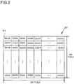
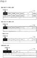
- An example of such image data is shown in Fig. 2 .
- Color information such as "FFFF" and "0000” and so on is held in sequence in the image data 20 shown in Fig. 2 .
- a display control device that draws an image that is separated into a plurality of display layers like the image in Fig. 1 , there is the problem that, when combining the images on the plurality of display layers using software, the time period required for processing is long.
- One cause for the processing time period related to combination of the images to become long is that, in some cases, the data for all the pixels in all the display layers is read out, irrespective of whether or not the pixel in the upper layer 300 is transparent in color. Since a pixel that is transparent in color is treated as being transparent during combination of the images, it would be possible to combine the images at higher speed if it were possible efficiently to skip over the pixels of transparent color that are not needed to be read out for combination of the image data. In this embodiment, it is arranged to increase the speed of processing for combining the images in the plurality of display layers by skipping over all the pixels of transparent color together.
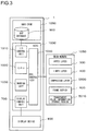
- Fig. 3 is a block diagram showing an example of a hardware structure for this navigation device that performs combination of images on different display layers.
- the navigation device 1 includes a SOC (System On Chip) 1000, a hard disk 1060, a display device 800, and a main memory 1050.
- the SOC 1000 includes an I/O (Input/Output) control unit 1010, a CPU (Central Processing Unit) 1020, a drawing unit 1030, a display control unit 700, and a bus controller 1040.
- I/O Input/Output
- CPU Central Processing Unit
- the SOC 1000 is connected to the main memory 1050, the hard disk 1060, and the display device 800.
- the CPU 1020, the drawing unit 1030, the display control unit 700, and the I/O control unit 1010 are connected to a memory bus that is controlled by the bus controller 1040.
- the bus controller 1040 In Fig. 3 , the fact that the structural elements of the SOC 1000 are connected to the memory bus is illustrated by them both being connected to the bus controller 1040.
- the SOC 1000 is connected to the main memory 1050 via the memory bus (i.e. via the bus controller 1040).
- the SOC 1000 is connected to the hard disk 1060 via the I/O control unit 1010.
- the SOC 1000 is connected to the display device 800 via the display control unit 700.
- the I/O control unit 1010 of the SOC 1000 accesses peripheral devices such as the hard disk 1060 and so on.
- a map database 900 in which map data for drawing the surroundings map 410 and so on, and image data for images of various types, such as the map mark 310 and the subject vehicle position mark 320 and so on, are stored in the hard disk 1060 that is accessed by the I/O control unit 1010.
- the CPU 1020 is able to control the I/O control unit 1010 to access the hard disk 1060, and is thereby able to read out map data and image data of various types from the hard disk 1060.
- the drawing unit 1030 of the SOC 1000 draws images of various types such as the map mark 310, the subject vehicle position mark 320, the surroundings map 410 and so on in display layers such as the upper layer 300 and the lower layer 400 and so on.
- the CPU 1020 determines the map range at which the surroundings map 410 should be drawn on the lower layer 400, and then the CPU 1020 accesses the hard disk 1060 via the I/O control unit 1010, and reads out the map data for this map range from the map database 900.
- the CPU 1020 controls the drawing unit 1030 and draws an image of the surroundings map 410 on the basis of the map data that has been read out from the map database 900.
- the CPU 1020 accesses the hard disk 1060 via the I/O control unit 1010, and reads out image data related to the map mark 310 and to the subject vehicle position mark 320. And, with the drawing unit 1030, the CPU 1020 draws an image on the upper layer 300 based upon this image data related to the map mark 310 and to the subject vehicle position mark 320 that has been acquired from the hard disk 1060.
- the main memory 1050 is a RAM (Random Access Memory), and is a working region for processing of various types executed by the SOC 1000.
- the upper layer 300, the lower layer 400, a compressed layer 5500, a frame buffer 600, and a transparent color information storage region 5310 are provided in the main memory 1050, and serve as storage regions in which data required for combining the display layers is temporarily stored.
- the frame buffer 600 is a storage region for storing image data to be outputted to the display device 800.
- the combined image data for the combined image 610 that is obtained by combining the image in the upper layer 300 and the image in the lower layer 400 is stored in this frame buffer 600.
- the compressed layer 5500 is a storage region that is used for storing compressed image data that has been obtained by compressing the image data for the upper layer 300.
- the transparent color information storage region 5310 is a storage region that is used for storing transparent color information that specifies which color in the image in the upper layer 300 is to be handled as being the transparent color.
- the image data, the combined image data, the compressed image data, and so on are stored in the main memory 1050 using a data structure such as, for example, a linked list structure or the like.
- a data structure such as, for example, a linked list structure or the like.
- the contents of this data can be read and written via pointer variables or the like used by software executed by the CPU 1020.
- the display control unit 700 of the SOC 1000 reads out image data from the frame buffer 600 and transmits it to the display device 800.
- the combined image data for the combined image 610 is transmitted by the display control unit 700 to the display device 800.
- the display device 800 is a liquid crystal monitor or the like, and performs output and display based upon the image data transmitted from the display control unit 700.
- the display device 800 displays the combined image 610.
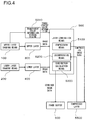
- Fig. 4 is a functional structural diagram of the navigation device 1 related to combination processing for combining the upper layer image 300 and the lower layer image 400 in order to obtain the combined image 610.
- the functional diagram of Fig. 4 includes an upper layer drawing means 100, a lower layer drawing means 200, the upper layer 300, the lower layer 400, a layer combination means 500, and the frame buffer 600.
- the upper layer drawing means 100, the lower layer drawing means 200, and the layer combination means 500 are implemented by software executed by the CPU 1020.
- the CPU 1020 controls the drawing unit 1030 and creates image data for the upper layer 300 based upon the image data for the map mark 310 and the subject vehicle position mark 320 and so on, and stores this data in the upper layer 300 of the main memory 1050.
- the upper layer drawing means 100 creates transparent color information, which is information related to the color in the upper layer 300 that is considered to be transparent, and stores this information in the transparent color information storage region 5310 of the main memory 1050.
- the color that is taken as being a transparent color in the transparent color information is treated as being transparent.
- the lower layer 400 shows through and is visible at the positions of those pixels, among the pixels in the upper layer 300, that have color information for the color that is taken as being the transparent color.
- the CPU 1020 controls the drawing unit 1030 and creates image data for the surroundings map 410, and stores this data in the lower layer 400 of the main memory 1050.
- the layer combination means 500 is executed under control by the CPU 1020, and includes three subroutines: a compression means 5100, a decompression means 5200, and a combination calculation means 5300.
- the compression means 5100 compresses image data that has been inputted according to the per se known run-length method, and stores the compressed image data that is the result of this compression in the compressed layer 5500 of the main memory 1050. And the decompression means 5200 reads in compressed image data stored in the compressed layer 5500, and recreates the original image data.
- the combination calculation means 5300 overlays together, pixel by pixel, the image data for a plurality of display layers that have been inputted on the basis of the transparent color information and thereby generates combined image data and stores this data in the frame buffer 600.
- the layer combination means 500 executes these three subroutines as appropriate, and thereby generates combined image data for the combined image 610 in which the image data for the upper layer 300 and the image data for the lower layer 400 are combined, and stores this data in the frame buffer 600.
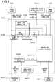
- the layer combination means of Fig. 5 includes a compression means 5100, a decompression means 5200, a combination calculation means 5300, a run-length counter 5400, a lower layer update flag 5600, and an upper layer update flag 5700.
- the run-length counter 5400 is used when the compression means 5100 compresses image data according to the per se known run-length method, and calculates the number of successive pixels in the image data for the upper layer 300 that have the same color information. In the following the number of successive pixels that have the same color information, as calculated by the run-length counter 5400, will be termed the "run-length".
- the run-length counter 5400 counts for how many pixels the color information "FFFF” continues, and thereby calculates a run-length of "4" for the successive color information "FFFF".
- the run-length counter 5400 counts the number of successive pixels having color information "0000” to the end of the row, and thereby calculates a run-length of "796" for the successive color information "0000".
- the compression means 5100 compresses the image data for the upper layer 300 by the per se known run-length method, and stores the resulting compressed image data for the upper layer 300 in the compressed layer 5500.
- This compressed image data stored by the compression means 5100 is stored as data pairs, each consisting of the color information of a pixel of image data in the upper layer 300, paired with the run-length of the succession of pixels having this color information.
- the decompression means 5200 reads out these data pairs from the compressed layer 5500.
- the result of compression of the image data 20 of Fig. 2 is shown in Fig. 6 as an example of processing by the compression means 5100.
- the compressed image data 60 shown in Fig. 6 is the result of compression by the compression means 5100 of the image data 20 of Fig. 2 .
- the data obtained by compressing the first row of the image data 20 of Fig. 2 is shown.
- this first row of the image data 20 after four successive pixels that have the color information "FFFF", there follow 796 successive pixels having the color information "0000".
- the layer combination means 500 is endowed with two processing modes. In the first of these processing modes, the layer combination means 500 executes the run-length counter 5400, the compression means 5100, and the combination calculation means 5300. In the following, this processing mode will be termed the "compression combination mode".
- the compression means 5100 compresses the image data for the updated upper layer 300, and stores the compressed image data that has been thus obtained in the compressed layer 5500.
- the combination calculation means 5300 generates combined image data for the combined image 610, one pixel at a time, on the basis of the image data and the transparent color information for the upper layer 300 and the image data for the lower layer 400, and stores this combined image data in the frame buffer 600.
- the layer combination means 500 executes the decompression means 5200 and the combination calculation means 5300. In the following, this processing mode will be termed the "uncompression combination mode".
- the decompression means 5200 reads in data pairs from the compressed image data for the upper layer 300 that are stored in the compressed layer 5500. As these data pairs are read in by the decompression means 5200, the layer combination means 500 inputs them to the combination calculation means 5300. And the combination calculation means 5300 generates combined image data for the combined image 610, one pixel at a time, on the basis of the data pairs read in by the decompression means 5200, the transparent color information for the upper layer 300, and the image data for the lower layer 400, and stores this combined image data in the frame buffer 600.
- the processing mode for the layer combination means 500 is selected on the basis of an upper layer update flag 5700 and a lower layer update flag 5600.
- the upper layer update flag 5700 is a flag that specifies whether or not the image data for the upper layer 300 has been updated.
- the lower layer update flag 5600 is a flag that specifies whether or not the image data for the lower layer 400 has been updated. It should be understood that, in the following, it will be supposed that all of the flags have either the value "0" or "1", and that they are stored in the main memory 1050.
- the layer combination means 500 operates in the compression combination mode.
- the layer combination means 500 operates in the uncompression combination mode if the lower layer update flag 5600 is set to "1".
- the upper layer update flag 5700 is controlled by the CPU 1020.
- the CPU 1020 sets the value of the upper layer update flag 5700 to "1".
- the lower layer update flag 5600 is also controlled by the CPU 1020, in a similar manner to the upper layer update flag 5700.
- the CPU 1020 sets the value of the lower layer update flag 5600 to "1".
- the layer combination means 500 inputs and acquires the image data and the transparent color information for the upper layer 300, and the image data for the lower layer 400.
- the image data for the upper layer 300 is inputted to the compression means 5100, to the combination calculation means 5300, and to the run-length counter 5400.
- the transparent color information for the upper layer 300 and the image data for the lower layer 400 are inputted to the combination calculation means 5300.
- the layer combination means 500 stores the data pair relating to this confirmed run-length in the compressed layer 5500, and also outputs this data pair to the combination calculation means 5300.
- the combination calculation means 5300 refers to the transparent color information for the upper layer 300, and makes a decision as to whether or not the color specified by the color information included in the data pair that has been outputted is the transparent color.
- the color information included in this data pair is the transparent color
- the amount of image data for the upper layer 300 specified by the run-length that is included in this data pair is skipped over, the image data for the upper layer 300 that has been skipped over is ignored, and combined image data is generated on the basis of the image data for the lower layer 400.
- the color specified by the color information included in this data pair is not the transparent color, then the image data for the upper layer 300 is not ignored.
- Transparent color information 71 and image data 72 are shown in Fig. 7A as one example of information related to the upper layer 300.
- the color information "0000" is set in the transparent color information 71 as being the transparent color.
- image data 73 is shown as one example of information related to the lower layer 400.
- the combined image data 74 that results from combination of the image data 72 and the image data 73 is shown in Fig. 7B .
- the run-length counter 5400 starts calculation of the run-length for the color information "FFFF".
- the run-length counter 5400 calculates a run-length of "4" for the color information "FFFF”
- the layer combination means 500 inputs the data pair "004 FFFF” to the combination calculation means 5300.
- the combination calculation means 5300 makes a decision as to whether or not the color information "FFFF" is the transparent color, on the basis of the transparent color information 71.
- the combination calculation means 5300 stores just “4" values in the frame buffer 600 consisting of the color information "FFFF” from the image data 72 of the upper layer 300.
- the run-length counter 5400 starts calculation of the run-length for the color information "0000".
- the layer combination means 500 inputs the data pair "31C 0000" to the combination calculation means 5300.
- the combination calculation means 5300 makes a decision as to whether or not the color information "0000" is the transparent color, on the basis of the transparent color information 71.
- the combination calculation means 5300 ignores the portion in the image data 72 consisting of the color information "0000”, and stores just “796” values in the frame buffer 600 consisting of the color information "1111” from the image data 73 of the lower layer 400.
- the result of the above is that combined image data 74 including "4" values consisting of the color information "FFFF” and “796” values consisting of the color information "1111” is stored in the frame buffer 600.
- the layer combination means 500 acquires the transparent color information for the upper layer 300, the image data for the lower layer 400, and the compressed image data in the compressed layer 5500 as input.
- the compressed image data in the compressed layer 5500 is inputted to the decompression means 5200.
- the data pairs in the compressed image data that has been read in by the decompression means 5200, the transparent color information for the upper layer 300, and the image data for the lower layer 400 are inputted to the combination calculation means 5300.
- the layer combination means 500 starts processing by the decompression means 5200. And, each time a data pair is read in by the decompression means 5200 from the compressed image data that is stored in the compressed layer 5500, this data pair that has been read in is outputted to the combination calculation means 5300. And the combination calculation means 5300 refers to the transparent color information for the upper layer 300, and makes a decision as to whether or not the color specified by the color information included in this data pair that has been outputted is the transparent color. And, if the color specified by the color information included in this data pair is the transparent color, then the color information specified by this data pair is ignored, and combined image data is generated on the basis of the image data for the lower layer 400. On the other hand, if the color specified by the color information included in this data pair is not the transparent color, then the color information specified by this data pair is not ignored, and combined image data is generated having the color information in this data pair and length equal to its run-length.
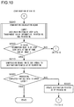
- Fig. 8 is a flow chart for processing to determine the processing mode for the layer combination means 500 on the basis of the value of the upper layer update flag 5700 and the value of the lower layer update flag 5600.
- the processing shown in Fig. 8 is executed by the CPU 1020.
- step S100 the CPU 1020 refers to the upper layer update flag 5700, and makes a decision as to whether or not this upper layer update flag 5700 is set to "1". If the upper layer update flag 5700 is set to "1", then the processing of Fig. 8 is transferred to a step S140, in which processing in the compression combination mode is started. On the other hand, if the upper layer update flag 5700 is reset to "0", then the processing of Fig. 8 proceeds to a step S110. In this step S110, the CPU 1020 refers to the lower layer update flag 5600, and makes a decision as to whether or not this lower layer update flag 5600 is set to "1".
- step S120 of Fig. 8 the CPU 1020 executes the layer combination means 500 in the uncompression combination mode.
- the processing of Fig. 8 proceeds to a step S130.
- step S130 of Fig. 8 the CPU 1020 resets the lower layer update flag 5600 to "0". And, when the lower layer update flag 5600 has been reset to "0", then the CPU 1020 returns the processing of Fig. 8 to the step S100.
- step S140 of Fig. 8 the CPU 1020 executes the layer combination means 500 in the compression combination mode.
- the processing of Fig. 8 proceeds to a step S150.
- step S150 of Fig. 8 the CPU 1020 resets the upper layer update flag 5700 to "0".
- step S160 of Fig. 8 the CPU 1020 resets the lower layer update flag 5600 to "0".
- the CPU 1020 returns the processing of Fig. 8 to the step S100.
- Figs. 9 and 10 are flow charts related to the processing executed by the CPU 1020 for the operation of the layer combination means 500 in the compression combination mode.
- pointer variables are used for the reading and writing of data to and from the upper layer 300, the lower layer 400, the frame buffer 600, and the compressed layer 5500.
- the pointer for reading in the image data for the upper layer 300 will be termed the "pointer RA”.
- the pointer for reading in the image data for the lower layer 400 will be termed the "pointer RB”.
- the pointer for writing the image data to the frame buffer 600 will be termed the "pointer WC”.
- pointer for writing the compressed image data to the compressed layer 5500 will be termed the "pointer WD".
- the CPU 1020 initializes these four pointers (the pointers RA, RB, WC, and WD).
- the pointer RA and the pointer RB are initialized so as to point at the data for the first pixels of the first rows of, respectively, the image data for the upper layer 300 and the image data for the lower layer 400.
- the pointers WC and WD are initialized so as to point at the first image data in the frame buffer 600 and the first image data in the compressed layer 5500, respectively.
- the way in which these four pointer variables are initialized is shown in Fig. 11 . In Fig.
- the pointer RA points at the storage region in which the data for the pixel at the start of the first row of the image data 111 for the upper layer 300 is stored.
- the pointer RB points at the storage region in which the data for the pixel at the start of the first row of the image data 112 for the lower layer 400 is stored.
- the pointer WC points at the storage region at the start of the frame buffer 600 in which the combined image data 113 is to be stored.
- the pointer WD points at the storage region at the start of the compressed layer 5500 in which the compressed image data 114 is to be stored.
- step S210 of Fig. 9 the CPU 1020 controls the run-length counter 5400 to initialize the run-length to 0.
- the CPU 1020 advances the processing for the layer combination means 500 in this compression combination mode to a step 220.
- the CPU 1020 reads in the image data, in other words the color information, for the upper layer 300 pointed at by the pointer RA.
- the CPU 1020 advances the processing for the layer combination means 500 in this compression combination mode to a step 230.
- the CPU 1020 updates the pointer RA to point at the next pixel in the upper layer 300.
- the way in which the pixel at which the pointer RA points is changed is shown in Fig. 12 .
- the data item in the image data 111 for the upper layer 300 at which the pointer RA points in Fig. 11 is updated one pixel to the right. It should be understood that, when the data item at which the pointer RA is pointing corresponds to the last pixel in its row, then it is updated so as to point at the first pixel in the next row.
- the CPU 1020 advances the processing for the layer combination means 500 in this compression combination mode to a step 240.
- the CPU 1020 makes decisions as to whether or not either one of the two conditions described below holds. If either the condition #1 or the condition #2 holds, then the CPU 1020 advances the flow of control of the layer combination means 500 in the compression combination mode to a step S250, while if neither one of these conditions #1 and #2 holds, then it advances the flow of control of the layer combination means 500 in the compression combination mode to a step S270.
- the condition #1 described below is one in which it is decided whether or not a succession of pixels having the same color information has terminated, and in which a decision is made as to whether or not the run-length for this color information has been fixed.
- condition #2 described below is for fixing the run-length, if a succession of pixels having the same color information straddles over rows.
- the decision in the condition #2 may, for example, be made by deciding whether or not the data pointed at by the pointer RA is the first pixel in a row.
- Condition #1 Is the color information read in by the step S220 the same as the color information pointed at by the pointer RA?
- Condition #2 Is the color information read in by the step S220 data at the end of some row of the image?
- the CPU 1020 controls the run-length counter, and adds "1" to the run-length. And, having added "1" to the run-length, the CPU 1020 advances the flow of control of the layer combination means 500 in the compression combination mode to the step S260.
- the CPU 1020 decides for a second time whether the condition #2 holds, and, if an affirmative decision has been reached, having fixed the run-length for the color information read by the step S220, the CPU 1020 advances the flow of control of the layer combination means 500 in the compression combination mode to the step S270, while, if a negative decision has been reached, the CPU 1020 returns the flow of control of the layer combination means 500 in the compression combination mode to the step S230.
- the CPU 1020 controls the compression means 5100, and writes a data pair consisting of the run-length at the time point of starting this step S270 and the color information read in by the step S220 at the destination pointed at by the pointer WD.
- this fixed data pair is stored in the compressed layer 5500. Having thus stored this fixed data pair in the compressed layer 5500, the CPU 1020 advances the flow of control of the layer combination means 500 in the compression combination mode to the step S280.
- the CPU 1020 updates the pointer WD to point at the next storage region in the compressed layer 5500. And, having thus updated the destination pointed at by the pointer WD to the next storage region in the compressed layer 5500, the CPU 1020 advances the flow of control of the layer combination means 500 in the compression combination mode to the step S290.
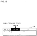
- FIG. 13 is an example showing the situation when the compressed image data 114 and the pointer WD thereto have been updated by the step S270 and the step S280.
- the data pair "004 FFFF" that consists of the color information "FFFF” for the image data 111 and its run-length of "4" is stored in the storage region pointed at by the pointer WD.
- the storage region pointed at by the pointer WD is advanced by one from the storage region pointed at in Fig. 11 .
- the run-length for the next color information "0000" of the image data 111 has been fixed, this will be stored in the storage region pointed at by the pointer WD in Fig. 13 .
- the CPU 1020 performs the processing of the combination calculation means 5300, while inputting the data pair that was written in the step S270, the transparent color information for the upper layer 300 stored in the transparent color information storage region 5310, the pointer RB, and the pointer WC. And, by executing the combination calculation means 5300, the CPU 1020 writes, in the storage region for the frame buffer 600, combined image data for a number of pixels equal to the run-length included in the data pair from the position at which the pointer WC points.
- An example of the result of executing the combined image data write processing performed by the step S290 is shown in Fig. 14. Fig.
- FIG. 14 is the output result of the combination calculation means 5300, to which the data pair "004 FFFF" written to the compressed image data 114 in the example of Fig. 13 , the transparent color information indicating that the color specified by the color information "FFFF" is not the transparent color, and the pointer RB and the pointer WC of Fig. 11 have been inputted.
- Fig. 14 including the position at which the pointer WC of Fig. 11 points, just four items of color information "FFFF" are stored.
- the position in the frame buffer 600 at which the pointer WC points has also shifted by just the run-length, so that it is shifted to the next storage region for writing data.
- the position at which the pointer RB that is the pointer to the image data in the lower layer 400 shifts is also updated by just the run-length during the processing of the step S290, together with the shifting of the pointer WC.
- the pixel positions in the upper layer 300, the lower layer 400, and the frame buffer 600 at which the pointer RA, the pointer RB, and the pointer WC respectively point become the same after the processing of the step S290 has been executed.
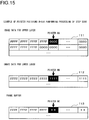
- An example of this is shown in Fig. 15.
- FIG. 15 is a figure showing the results of executing the processing of the step S290 upon the pointer RA, the pointer RB, and the pointer WC shown in Fig. 11 .
- the pointer RA has been shifted four elements from the position of Fig. 11 to the position shown in Fig. 15 , since the step S230 of Fig. 9 was executed four times, until the run-length of the color information "FFFF" that was read in by the step S220 was fixed.
- the pointer WC has been shifted in the step S290 by just the amount of the run-length (in this case, by four elements) while writing the combined image data pixel by pixel in the frame buffer 600.
- the pointer RB has been shifted to match the pointer WC.
- the CPU 1020 advances the flow of control to a step S300.
- the CPU 1020 makes a decision for a second time as to whether or not the condition #2 holds. If an affirmative decision is reached, then the CPU 1020 advances the processing of the layer combination means 500 in the compression combination mode to a step S310, while, if a negative decision is reached for this condition #2, then the CPU 1020 returns the processing to the step S220 of Fig. 9 .
- the CPU 1020 controls the compression means 5100 and writes the end symbol "000" in the storage region at which the pointer WD points. And, having thus written the end symbol "000" in the destination at which the pointer WD points, then the CPU 1020 advances the processing of the layer combination means 500 in the compression combination mode to a step S320.
- the CPU 1020 makes a decision as to whether or not the processing of the layer combination means 500 in the compression combination mode has been completed for all of the data included in the image data for the upper layer 300. This decision may be performed by deciding whether or not, for example, the pointer RA is pointing at "null". If an affirmative decision is reached, then the CPU 1020 terminates this processing of the layer combination means 500 in the compression combination mode, whereas if a negative decision is reached, then the CPU 1020 advances this processing of the layer combination means 500 in the compression combination mode to a step S330.
- the CPU 1020 shifts the storage region at which the pointer WD points to the first item of the next row of the compressed image data.
- An example of the result of executing this processing of the step S330 is shown in Fig. 16 .
- the first row of the compressed image data 114 ends with the end symbol "000", and the pointer WD points at the data in the second row.
- the CPU 1020 returns the processing of the layer combination means 500 in the compression combination mode to the step S220 of Fig. 9 .
- the combination calculation means shown in Fig. 17 is processing executed by the CPU 1020, and, for its input, it needs the data pair PA related to the upper layer 300, the read pointer RB for the lower layer 400, the transparent color information for the upper layer 300, and the write pointer WC to the frame buffer 600.
- the number of repetitions N is used as an internal variable.
- the CPU 1020 initializes the number of repetitions N to 0. And, after having initialized the number of repetitions N to 0, the CPU 1020 advances the processing of the combination calculation means 5300 to a step S410.
- the CPU 1020 makes a decision as to whether or not the color information included in the data pair PA that has been inputted is the transparent color. If the color information included in this data pair PA is the transparent color, then the CPU 1020 advances the processing of the combination calculation means 5300 to a step S420, whereas, if the color information included in this data pair PA is not the transparent color, then it advances the processing to a step S470.
- the CPU 1020 stores (i.e. copies) the color information pointed at by the pointer RB to the storage region pointed at by the pointer WC. And, after having thus copied the color information pointed at by the pointer RB to the storage region pointed at by the pointer WC, then the CPU 1020 advances the processing of the combination calculation means 5300 to a step S430.
- step S430 of Fig. 17 the CPU 1020 updates the destination at which the pointer RB points to the next data item in the lower layer 400. And, after having thus updated the destination at which the pointer RB points, then the CPU 1020 advances the processing of the combination calculation means 5300 to a step S440.
- step S440 of Fig. 17 the CPU 1020 updates the destination at which the pointer WC points to the next storage region of the frame buffer 600. And, after having thus updated the destination at which the pointer WC points, then the CPU 1020 advances the processing of the combination calculation means 5300 to a step S450.
- step S450 of Fig. 17 the CPU 1020 adds "1" to the number of repetitions N. And, after having thus added "1" to the number of repetitions N, then the CPU 1020 advances the processing of the combination calculation means 5300 to a step S460.
- the CPU 1020 makes a decision as to whether or not the number of repetitions N has reached the same value as the run-length of the data pair PA. In other words, it makes a decision as to whether or not the processing from the step S420 to the step S440 has been repeated by just a number of times equal to the run-length of the data pair PA. If the number of repetitions N has reached the same value as the run-length of the data pair PA, then the CPU 1020 terminates this processing by the combination calculation means 5300, whereas, if the number of repetitions N is still lower than the run-length of the data pair PA, then the CPU 1020 returns the processing of the combination calculation means 5300 to the step S420.
- step S470 of Fig. 17 since the color information included in the data pair PA is not the transparent color, accordingly the CPU 1020 stores this color information in the storage region of the frame buffer 600 at which the pointer WC points. And, after having stored this color information included in the data pair PA in the storage region of the frame buffer 600 at which the pointer WC points, then the CPU 1020 advances the processing of the combination calculation means 5300 to a step S480.
- step S480 of Fig. 17 the CPU 1020 updates the destination at which the pointer RB points to the next data item in the lower layer 400. And, after having thus updated the destination at which the pointer RB points, then the CPU 1020 advances the processing of the combination calculation means 5300 to a step S490.
- step S490 of Fig. 17 the CPU 1020 updates the destination at which the pointer WC points to the next storage region of the frame buffer 600. And, after having thus updated the destination at which the pointer WC points, then the CPU 1020 advances the processing of the combination calculation means 5300 to a step S500.
- step S500 of Fig. 17 the CPU 1020 adds "1" to the number of repetitions N. And, after having thus added "1" to the number of repetitions N, then the CPU 1020 advances the processing of the combination calculation means 5300 to a step S510.
- the CPU 1020 makes a decision as to whether or not the number of repetitions N has reached the same value as the run-length of the data pair PA. If the number of repetitions N has reached the same value as the run-length of the data pair PA, then the CPU 1020 terminates this processing by the combination calculation means 5300, whereas, if the number of repetitions N is still lower than the run-length of the data pair PA, then the CPU 1020 returns the processing of the combination calculation means 5300 to the step S470.
- the combination calculation means 5300 of Fig. 17 decides whether or not all of the pixels included in the data pair PA (the number of which is run-length) are transparent in color. By doing this, it is possible to perform combination of the display layers at higher speed than with the prior art technique, in which it was decided whether the pixels were transparent in color or not pixel by pixel.
- Fig. 18 is a flow chart related to the processing executed by the CPU 1020 for the operation of the layer combination means 500 in the uncompression combination mode.
- the CPU 1020 initializes three pointers (i.e. the pointers RD, RB, and WC).
- the pointer RB and the pointer WC are the same as those explained in connection with Fig. 9 .
- the pointer RB is the pointer for reading in the image data of the lower layer 400.
- the pointer WC is the pointer for writing the combined image data to the frame buffer 600.
- the pointer RD is a pointer for reading in the compressed image data from the compressed layer 5500, in other words a pointer for reading in data pairs from the compressed layer 5500.
- the CPU 1020 initializes the pointer RB so that it points at the image data for the first pixel in the first row of the lower layer 400.
- the CPU 1020 initializes the pointer WC so that it points at the first storage region in the frame buffer 600. Moreover, the CPU 1020 initializes the pointer RD so that it points at the first data pair in the compressed layer 5500. When the CPU 1020 has completed initialization of these three pointers, it advances the processing of the layer combination means 500 in the uncompression combination mode to a step S610.
- the CPU 1020 reads in the data pair from the storage region of the compressed layer 5500 at which the pointer RD points. And, having read in the data pair from the storage region of the compressed layer 5500 at which the pointer RD points, then the CPU 1020 advances the processing of the layer combination means 500 in the uncompression combination mode to a step S620.
- the CPU 1020 makes a decision as to whether or not the end symbol "000” has been read in by the step S610. If the end symbol "000” has been read in then the CPU 1020 advances the processing of the layer combination means 500 in the uncompression combination mode to a step S640, while if the end symbol "000” has not been read in then it advances the processing to a step S630.
- the CPU 1020 executes the processing of the combination calculation means 5300 shown in Fig. 17 , using as input the data pair read in by the step S610, the transparent color information for the upper layer 300 stored in the transparent color information storage region 5310, the pointer RB, and the pointer WC. And, having completed the processing of the combination calculation means 5300, the CPU 1020 advances the processing of the layer combination means 500 in the uncompression combination mode to the step S640.
- the CPU 1020 updates the destination pointed at by the pointer RD to the next data pair in the compressed layer 5500. But, if the end symbol "000" was read in by the step S610, then the CPU 1020 updates the destination pointed at by the pointer RD to the first data pair in the next row of the compressed layer 5500. And, having updated the destination pointed at by the pointer RD, the CPU 1020 advances the processing of the layer combination means 500 in the uncompression combination mode to a step S650.
- the CPU 1020 makes a decision as to whether or not the processing of the combination calculation means 5300 has been executed for all of the data pairs stored in the compressed layer 5500. For example, the CPU 1020 may decide whether or not the end symbol "000" in the final row of the compressed layer 5500 is being pointed at by the pointer RD.
- the CPU 1020 If the CPU 1020 has decided that the processing of the combination calculation means 5300 has been executed for all of the data pairs stored in the compressed layer 5500, then it terminates the processing of the layer combination means 500 in the uncompression combination mode, whereas if it has decided that the processing of the combination calculation means 5300 has not been completed for all of the data pairs, then it returns the processing of the layer combination means 500 in the uncompression combination mode to the step S610.
- the display control device of this embodiment is a navigation device 1 that displays, upon the display device 800, combined image data obtained by combining the image data for a plurality of display layers, i.e. for the upper layer 300 and for the lower layer 400.
- the images upon the upper layer 300 and the lower layer 400 are made up of a plurality of pixels 21, and this image data includes color information related to the color of each of the plurality of pixels 21.
- the color information for handling the transparent color in the image data for the upper layer 300 is stored as transparent color information in the transparent color information storage region 5310 of the main memory 1050.
- the CPU 1020 makes decisions as to whether or not the image data for each of the upper layer 300 and the lower layer 400 has been updated, and controls the upper layer update flag 5700 and the lower layer update flag 5600 accordingly.
- This navigation device 1 is provided with the run-length counter 5400 that calculates the run-length related to the color information included in the image data for the upper layer 300, the combination calculation means 5300 that combines the image data for the upper layer 300 and the image data for the lower layer 400 and generates the combined image data, and the display control unit 700 that outputs the combined image data generated by the combination calculation means 5300 to the display device 800, in order to display the combined image upon the display device 800. And, when the upper layer 300 has been updated and the upper layer update flag 5700 has been set to "1", in the step S410 of Fig.
- the combination calculation means 5300 of the navigation device 1 makes a decision for the calculated number run-length of pixels all together, the run-length being calculated by the run-length counter 5400 controlled by the CPU 1020 in the steps S210 through S270 of Fig. 9 , as to whether or not the color information of the pixels is the transparent color (in the step S290 of Fig. 10 and the step S630 of Fig. 18 ).
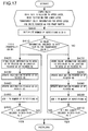
- Fig. 19 shows a case in which, to the functional block diagram of the layer combination means 500 shown in Fig. 5 , there is added a structure for implementing write prohibition processing for preventing writing of compressed image data to the compressed layer 5500.
- a reusable/not reusable flag 5800 is added to the functional block diagram of Fig. 5 .
- This reusable/not reusable flag 5800 is controlled by the CPU 1020, and is set to "1" when the image data of the upper layer 300 is a moving image (video) or the like, and if it is updated by the upper layer drawing means 100 more frequently than a predetermined frame rate.
- this reusable/not reusable flag 5800 is set to "1"
- writing of the compressed image data to the compressed layer 5500 by the compression means 5100 is prohibited.
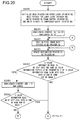
- a step S800 is added before the step S270.
- the CPU 1020 makes a decision as to whether or not the reusable/not reusable flag 5800 is set to "1". If in this step S800 of Fig. 21 the reusable/not reusable flag 5800 is set to "1", then the CPU 1020 advances the processing of the layer combination means 500 in the compression combination mode to a step S810, while if the reusable/not reusable flag 5800 is reset to "0", then the CPU 1020 advances the processing of the layer combination means 500 in the compression combination mode to the step S270. When the processing of the layer combination means 500 in the compression combination mode is advanced to the step S270, then the subsequent processing is the same as the processing in Fig. 10 .
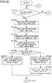
- the processing of the steps S810 through S830 of Fig. 21 is the processing subsequent to the step S270 of the flow chart relating to the layer combination means 500 in the compression combination mode shown in Figs. 9 and 10 , with the step S270, the step S280, the step S310, and the step S330 being omitted.
- the CPU 1020 executes the processing of the combination calculation means 5300.
- the CPU 1020 writes combined image data for a total number of pixels from the position at which the pointer WC points, equal to the run-length value included in the data pair.
- the CPU advances the flow of control to a step S820.
- the CPU 1020 makes a decision as to whether or not the condition #2 (described above in the explanation of Fig. 9 ) holds. If the CPU 1020 decides that the condition #2 holds, then it advances the processing of the layer combination means 500 in the compression combination mode to a step S830, whereas, if the CPU 1020 decides that the condition #2 does not hold, then it returns the processing to the step S220 of Fig. 20 .
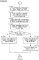
- the CPU 1020 makes a decision as to whether or not the processing of the layer combination means 500 in the compression combination mode has been completed for all of the data included in the image data for the upper layer 300. This decision may, for example, be made by determining whether or not the pointer RA is pointing at "null". If an affirmative decision is reached, then the CPU 1020 terminates the processing of the layer combination means 500 in the compression combination mode, whereas if a negative decision is reached, then the CPU 1020 returns the processing of the layer combination means 500 in the compression combination mode to the step S220 of Fig. 20 .
Landscapes
- Engineering & Computer Science (AREA)
- General Physics & Mathematics (AREA)
- Physics & Mathematics (AREA)
- Radar, Positioning & Navigation (AREA)
- Remote Sensing (AREA)
- Multimedia (AREA)
- Theoretical Computer Science (AREA)
- Signal Processing (AREA)
- Computer Hardware Design (AREA)
- Automation & Control Theory (AREA)
- Compression Of Band Width Or Redundancy In Fax (AREA)
- Controls And Circuits For Display Device (AREA)
- Processing Or Creating Images (AREA)
- Image Generation (AREA)
Claims (3)
- Anzeigesteuervorrichtung, die auf
einer Anzeigevorrichtung (800) kombinierte Bilddaten anzeigt, die durch Kombinieren von Bilddaten von mehreren Anzeigeschichten erhalten wurden, die
eine oder mehrere obere Schichten (300) und
eine unterste Schicht (400) umfassen, wobei jede der mehreren Anzeigeschichten aus mehreren Pixeln besteht, wobei die Bilddaten einer jeden der mehreren Anzeigeschichten Farbinformationen enthalten, die sich auf die Farben der mehreren in der Anzeigeschicht enthaltenen Pixel beziehen, wobei die Anzeigesteuervorrichtung umfasst:eine Speichereinheit für Informationen über transparente Farbe (5310), die konfiguriert ist, Informationen über transparente Farbe zu speichern, die Farbinformationen einer transparenten Farbe in den Bilddaten für jede der einen oder mehreren oberen Schichten (300) bestimmen;einen Lauflängenzähler (5400), der konfiguriert ist, eine Lauflänge zu berechnen, die für die in den Bilddaten für jede der einen oder mehreren oberen Schichten (300) enthaltenen Farbinformationen die Anzahl von aufeinanderfolgenden Pixeln mit denselben Farbinformationen bestimmt;Kompressionsmittel (5100), die konfiguriert sind,Bilddaten der einen oder mehreren oberen Schichten (300) anhand der durch den Lauflängenzähler (5400) gezählten Lauflänge zu komprimieren unddie komprimierten Bilddaten als Datenpaare zu speichern, die aus den Farbinformationen eines Pixels der Bilddaten in der einen oder den mehreren oberen Schichten (300) gepaart mit der Lauflänge der Folge von Pixeln mit diesen Farbinformationen bestehen; undKombinationsberechnungsmittel (5300), die konfiguriert sind, die Bilddaten der einen oder mehreren oberen Schichten (300) zu kombinieren, um die kombinierten Bilddaten zu erzeugen; undeine Anzeigeeinheit für kombinierte Bilddaten, die konfiguriert ist, die durch die Kombinationsberechnungsmittel (5300) erzeugten kombinierten Bilddaten an die Anzeigevorrichtung auszugeben, um das kombinierte Bild auf der Anzeigevorrichtung anzuzeigen, wobeidie Kombinationsberechnungsmittel (5300) konfiguriert sind, sich auf die Farbinformationen gepaart mit der Lauflänge zu beziehen und dann, wenn die in diesem Datenpaar enthaltenen Farbinformationen die transparente Farbe sind, die Menge an Bilddaten der einen oder mehreren oberen Schichten (300), die durch die Lauflänge bestimmt wird, die in diesem Datenpaar enthalten ist, übersprungen wird, und kombinierte Bilddaten anhand der Bilddaten der untersten Schicht (400) ohne Berücksichtigung der Bilddaten der einen oder mehreren oberen Schichten (300) für die Lauflänge erzeugt werden und dann, wenn die in diesem Datenpaar enthaltenen Farbinformationen nicht die transparente Farbe sind, die Bilddaten der einen oder mehreren oberen Schichten (300) nicht übergangen werden, wobei die Anzeigesteuervorrichtung ferner umfasst:eine Aktualisierungsentscheidungseinheit der oberen Schicht, die konfiguriert ist, für jede der einen oder mehreren oberen Schichten (300) unter den mehreren Anzeigeschichten, die von der untersten Anzeigeschicht (400) verschieden sind, zu entscheiden, ob die Bilddaten für diese obere Schicht (300) aktualisiert wurden oder nicht;eine Aktualisierungsentscheidungseinheit der unteren Schicht, die konfiguriert ist, zu entscheiden, ob die Bilddaten für die unterste Schicht (400) unter den mehreren Anzeigeschichten aktualisiert wurde oder nicht;Dekompressionsmittel (5200), die konfiguriert sind, aus den komprimierten Bilddaten, die in jeder der komprimierten Schichten (5500) gespeichert sind, die Farbinformationen und die Lauflänge dieser Farbinformationen zu lesen, wobeidie Kombinationsberechnungsmittel (5300) konfiguriert sind:die kombinierten Bilddaten durch fortlaufendes Kombinieren der Bilddaten für die eine oder die mehreren oberen Schichten (300) mit den Bilddaten für die unterste Schicht (400) in einer ansteigenden hierarchischen Reihenfolge von der untersten Schicht (300) der kleinsten Ordnung zu erzeugen;für jede obere Schicht (30) unter der einen oder den mehreren oberen Schichten (300), für die durch die Aktualisierungsentscheidungseinheit der oberen Schicht entschieden wurde, dass die Bilddaten aktualisiert wurden, die Bilddaten dieser oberen Schicht (300) mit den Bilddaten der untersten Schicht (400) anhand der durch den Lauflängenzähler (5400) berechneten Lauflänge zu kombinieren, wenn die Kompressionsmittel (5100) die komprimierten Bilddaten der Bilddaten erzeugen; undfür jede der einen oder der mehreren oberen Schichten (300), für die durch die Aktualisierungsentscheidungseinheit nicht entschieden wurde, dass die Bilddaten aktualisiert wurden, dann, wenn entschieden wurde, dass die Bilddaten der untersten Schicht (400) aktualisiert wurden, die Bilddaten dieser oberen Schicht (300) mit den Bilddaten der untersten Schicht (400) anhand der Farbinformationen und der Lauflängenauslesung durch die Dekompressionsmittel (5200) aus den komprimierten Bilddaten, die in Übereinstimmung mit der oberen Schicht (300) gespeichert wurden, zu kombinieren. - Anzeigesteuervorrichtung nach Anspruch 1, die ferner umfasst:eine Bildaktualisierungsfrequenzentscheidungseinheit, die konfiguriert ist, eine Entscheidung zu treffen, ob die Bilddaten einer jeden der einen oder mehreren oberen Schichten (300) öfter als eine vorgegebene Rahmenrate aktualisiert werden, wobeidann, wenn durch die Bildaktualisierungsfrequenzentscheidungseinheit entschieden wurde, dass die Bilddaten einer der einen oder der mehreren oberen Schichten (300) öfter als die vorgegebene Rahmenrate aktualisiert werden, und darüber hinaus, wenn die Bilddaten der oberen Schicht (300) aktualisiert wurden,die Kombinationsberechnungsmittel (5300) konfiguriert sind, die Kompressionsmittel (5100) daran zu hindern, die komprimierten Bilddaten in der komprimierten Schicht (5500), die dieser oberen Schicht (300) entspricht, zu speichern.
- Anzeigeschichtkombinationsprogramm zum Bewirken, dass eine CPU Bilddaten von mehreren in einem Speicher gespeicherten Anzeigeschichten kombiniert, wobei:jede der mehreren Anzeigeschichten aus mehreren Pixeln besteht;die Bilddaten einer jeden der mehreren Anzeigeschichten Farbinformationen enthalten, die sich auf die Farben der mehreren in dieser Anzeigeschicht enthaltenen Pixel beziehen;Informationen über transparente Farbe, die Farbinformationen für eine transparente Farbe in den Bilddaten einer jeden der mehreren Anzeigeschichten außer für die untersten Anzeigeschicht bestimmen, in dem Speicher gespeichert werden;das Programm bewirkt, dass die CPU arbeitet als:ein Lauflängenzähler (5400), der eine Lauflänge berechnet, die für die in den Bilddaten einer jeden der mehreren Anzeigeschichten außer der untersten Anzeigeschicht (400) enthaltenen Bilddaten die Anzahl von aufeinanderfolgenden Pixeln mit denselben Farbinformationen bestimmt; undKombinationsberechnungsmittel (5300), die die Bilddaten der mehreren Anzeigeschichten durch Pixeleinheiten kombinieren, um die kombinierten Bilddaten zu erzeugen; unddann, wenn für eine Anzeigeschicht unter den mehreren Anzeigeschichten, die von der untersten Schicht (400) verschieden sind, die Farbinformationen für eine Gesamtheit von Lauflängenpixeln, die durch den Lauflängenzähler (5400) berechnet wurden, eine transparente Farbe sind, die Kombinationsberechnungsmittel (5300) durch Übergehen der Bilddaten für die Gesamtanzahllauflänge von aufeinanderfolgenden Pixeln eine Kombination ausführen, wobei:das Programm ferner bewirkt, dass die CPU arbeitet als:eine Aktualisierungsentscheidungseinheit der oberen Schicht, dass für jede der einen oder mehreren oberen Schichten (300) unter den mehreren Anzeigeschichten, die von der untersten Anzeigeschicht (400) verschieden sind, entscheidet, ob die Bilddaten für diese obere Schicht (300) aktualisiert wurden oder nicht;eine Aktualisierungsentscheidungseinheit der unteren Schicht, die entscheidet, ob die Bilddaten für die unterste Schicht (400) unter den mehreren Anzeigeschichten aktualisiert wurden oder nicht;Kompressionsmittel (5100), die komprimierte Bilddaten anhand von Farbinformationen und der Lauflänge dieser Farbinformationen, die durch den Lauflängenzähler (5400) berechnet wurden, die in den Bilddaten für jede der einen oder mehreren oberen Schichten (300) enthalten sind, erzeugen; unddie komprimierten Bilddaten in einer oder mehreren komprimierten Schichten (5500), die der einen oder den mehreren oberen Schichten (300) entsprechen, speichern; undDekompressionsmittel (5200), die aus den in jeder der komprimierten Schichten (5500) gespeicherten komprimierten Bilddaten die Farbinformationen und die Lauflänge dieser Farbinformationen auslesen; unddie Kombinationsberechnungsmittel (5300):die kombinierten Bilddaten durch fortlaufendes Kombinieren der Bilddaten der einen oder mehreren oberen Schichten (300) mit den Bilddaten der untersten Schicht (400) in einer ansteigenden hierarchischen Reihenfolge von der untersten Schicht (300) der kleinsten Ordnung erzeugen;für jede der einen oder mehreren oberen Schichten (300), für die durch die Aktualisierungsentscheidungseinheit der oberen Schicht entschieden wurde, dass die Bilddaten aktualisiert wurden, die Bilddaten dieser oberen Schicht (300) mit den Bilddaten der untersten Schicht (400) anhand der durch den Lauflängenzähler (5400) berechneten Lauflänge kombinieren, wenn die Kompressionsmittel (5100) die komprimierten Bilddaten der Bilddaten erzeugen; undfür jede der einen oder mehreren oberen Schichten (300), für die durch die Aktualisierungsentscheidungseinheit der oberen Schicht nicht entschieden wurde, dass die Bilddaten aktualisiert wurden, dann, wenn entschieden wurde, dass die Bilddaten der untersten Schicht (400) aktualisiert wurden, die Bilddaten für diese obere Schicht (300) mit den Bilddaten für die unterste Schicht (400) anhand der Farbinformationen und der durch die Dekompressionsmittel (5200) aus den komprimierten Bilddaten, die in Übereinstimmung mit der oberen Schicht (300) gespeichert wurden, ausgelesenen Lauflänge kombinieren.
Applications Claiming Priority (1)
| Application Number | Priority Date | Filing Date | Title |
|---|---|---|---|
| JP2010285838A JP5740149B2 (ja) | 2010-12-22 | 2010-12-22 | 表示制御装置、表示レイヤ合成プログラム |
Publications (2)
| Publication Number | Publication Date |
|---|---|
| EP2469504A1 EP2469504A1 (de) | 2012-06-27 |
| EP2469504B1 true EP2469504B1 (de) | 2016-05-11 |
Family
ID=45491258
Family Applications (1)
| Application Number | Title | Priority Date | Filing Date |
|---|---|---|---|
| EP11194380.9A Active EP2469504B1 (de) | 2010-12-22 | 2011-12-19 | Anzeigsteuervorrichtung und Anzeigeschicht-Kombinationsprogramm |
Country Status (4)
| Country | Link |
|---|---|
| US (1) | US8803905B2 (de) |
| EP (1) | EP2469504B1 (de) |
| JP (1) | JP5740149B2 (de) |
| CN (1) | CN102543042B (de) |
Families Citing this family (17)
| Publication number | Priority date | Publication date | Assignee | Title |
|---|---|---|---|---|
| US20140204107A1 (en) * | 2013-01-22 | 2014-07-24 | Vixs Systems, Inc. | Video processor with frame buffer compression and methods for use therewith |
| KR20150025594A (ko) * | 2013-08-29 | 2015-03-11 | 삼성전자주식회사 | 멀티 이미지 레이어 컴포지트 방법 |
| KR20150033162A (ko) * | 2013-09-23 | 2015-04-01 | 삼성전자주식회사 | 컴포지터, 이를 포함하는 시스템온칩 및 이의 구동 방법 |
| JP6230366B2 (ja) * | 2013-10-16 | 2017-11-15 | オリンパス株式会社 | 画像出力装置および画像出力方法 |
| US20150170617A1 (en) * | 2013-12-16 | 2015-06-18 | Kabushiki Kaisha Toshiba | Electronic device, method, and storage medium |
| KR102120865B1 (ko) * | 2014-01-14 | 2020-06-17 | 삼성전자주식회사 | 디스플레이 장치, 디스플레이 장치의 드라이버, 이를 포함하는 전자 장치 및 디스플레이 시스템 |
| CN104504496A (zh) * | 2014-12-02 | 2015-04-08 | 成都万象天龙科技有限公司 | 一种基于进销存系统的控制系统与控制方法 |
| CN104537456A (zh) * | 2014-12-02 | 2015-04-22 | 成都万象天龙科技有限公司 | 一种基于进销存系统的带加密管控功能的控制系统与控制方法 |
| CN104537455A (zh) * | 2014-12-02 | 2015-04-22 | 成都万象天龙科技有限公司 | 一种基于进销存系统的带加密功能的控制系统与控制方法 |
| KR102287400B1 (ko) * | 2015-02-03 | 2021-08-06 | 삼성전자주식회사 | 이미지 합성 장치와 이를 포함하는 디스플레이 시스템 |
| US9858697B2 (en) * | 2016-01-07 | 2018-01-02 | Livio, Inc. | Methods and systems for communicating a video image |
| JPWO2017187508A1 (ja) * | 2016-04-26 | 2019-03-07 | オリンパス株式会社 | 表示処理装置および撮像装置 |
| US10163184B2 (en) * | 2016-08-17 | 2018-12-25 | Adobe Systems Incorporated | Graphics performance for complex user interfaces |
| KR102449834B1 (ko) * | 2017-02-17 | 2022-09-29 | 스미도모쥬기가이고교 가부시키가이샤 | 작업기계용 주변감시 시스템 |
| CN108572807A (zh) * | 2017-03-14 | 2018-09-25 | 深圳市中兴微电子技术有限公司 | 一种降低显示控制器带宽消耗的方法及装置 |
| WO2019021484A1 (ja) * | 2017-07-28 | 2019-01-31 | オリンパス株式会社 | 表示処理装置および撮像装置 |
| US11681659B2 (en) * | 2021-05-21 | 2023-06-20 | Red Hat, Inc. | Hybrid file compression model |
Citations (1)
| Publication number | Priority date | Publication date | Assignee | Title |
|---|---|---|---|---|
| EP0855680A1 (de) * | 1997-01-24 | 1998-07-29 | Océ-Technologies B.V. | Manipulation von in Lauflänge kodierten Bildern |
Family Cites Families (17)
| Publication number | Priority date | Publication date | Assignee | Title |
|---|---|---|---|---|
| JPS59168786A (ja) * | 1983-03-15 | 1984-09-22 | Sony Corp | テレビ静止画像伝送装置 |
| JP2791523B2 (ja) * | 1992-01-30 | 1998-08-27 | 大日本スクリーン製造株式会社 | 線画データ合成装置 |
| JP2813929B2 (ja) * | 1992-02-26 | 1998-10-22 | 大日本スクリーン製造株式会社 | 線画データ合成装置 |
| JPH0728986A (ja) * | 1993-07-09 | 1995-01-31 | Fuji Xerox Co Ltd | 画像合成処理装置 |
| JPH11313339A (ja) * | 1998-04-30 | 1999-11-09 | Toshiba Corp | 表示制御装置および動画/グラフィクス合成表示方法 |
| JP4026098B2 (ja) | 1998-09-24 | 2007-12-26 | 沖電気工業株式会社 | 表示コントローラ |
| JP2000134576A (ja) * | 1998-10-28 | 2000-05-12 | Roland Corp | タイトル映像の保存再生装置 |
| JP3409734B2 (ja) | 1999-04-20 | 2003-05-26 | 日本電気株式会社 | 画像合成システム及び方法 |
| JP2003288071A (ja) | 2002-03-28 | 2003-10-10 | Fujitsu Ltd | 画像処理装置および半導体装置 |
| JP2004015286A (ja) * | 2002-06-05 | 2004-01-15 | Seiko Epson Corp | ディジタルカメラ |
| JP2004037632A (ja) * | 2002-07-01 | 2004-02-05 | Seiko Epson Corp | 画像表示制御装置、表示装置及び電子機器 |
| JP2004070221A (ja) | 2002-08-09 | 2004-03-04 | Aisin Aw Co Ltd | 地図表示装置及び地図表示用プログラム |
| JP3946676B2 (ja) * | 2003-08-28 | 2007-07-18 | 株式会社東芝 | 撮影画像処理装置及びその方法 |
| EP1718065A1 (de) * | 2005-04-30 | 2006-11-02 | STMicroelectronics (Research & Development) Limited | Verfahren und Vorrichtung zur Bilddatenverarbeitung |
| US8018472B2 (en) * | 2006-06-08 | 2011-09-13 | Qualcomm Incorporated | Blending multiple display layers |
| JP2008305030A (ja) * | 2007-06-05 | 2008-12-18 | Denso Corp | 合成画像生成装置 |
| JP5495170B2 (ja) | 2009-06-15 | 2014-05-21 | Toto株式会社 | 衛生洗浄装置システム |
-
2010
- 2010-12-22 JP JP2010285838A patent/JP5740149B2/ja active Active
-
2011
- 2011-12-19 EP EP11194380.9A patent/EP2469504B1/de active Active
- 2011-12-21 US US13/333,206 patent/US8803905B2/en active Active
- 2011-12-21 CN CN201110432139.XA patent/CN102543042B/zh active Active
Patent Citations (1)
| Publication number | Priority date | Publication date | Assignee | Title |
|---|---|---|---|---|
| EP0855680A1 (de) * | 1997-01-24 | 1998-07-29 | Océ-Technologies B.V. | Manipulation von in Lauflänge kodierten Bildern |
Also Published As
| Publication number | Publication date |
|---|---|
| US8803905B2 (en) | 2014-08-12 |
| JP2012133178A (ja) | 2012-07-12 |
| CN102543042A (zh) | 2012-07-04 |
| EP2469504A1 (de) | 2012-06-27 |
| US20120162243A1 (en) | 2012-06-28 |
| CN102543042B (zh) | 2015-02-25 |
| JP5740149B2 (ja) | 2015-06-24 |
Similar Documents
| Publication | Publication Date | Title |
|---|---|---|
| EP2469504B1 (de) | Anzeigsteuervorrichtung und Anzeigeschicht-Kombinationsprogramm | |
| KR900004019B1 (ko) | 칼라 화상 표시 시스템 | |
| CN101065784B (zh) | 计算机图形处理 | |
| US6833835B1 (en) | Method and apparatus for antialiased imaging of graphical objects | |
| KR100482708B1 (ko) | 리스트제어비디오동작방법및시스템 | |
| US8717385B2 (en) | Image display control apparatus | |
| US6373462B1 (en) | Method and apparatus for displaying higher color resolution on a hand-held LCD device | |
| EP1378884A1 (de) | Vorrichtung und verfahren zur bildzusammensetzung | |
| US6369827B1 (en) | Method and apparatus for displaying higher color resolution on a hand-held LCD device | |
| KR20130095206A (ko) | 신호 처리 장치 및 반도체 장치 | |
| JP2617007B2 (ja) | 対話型大画像処理方法 | |
| EP0887768B1 (de) | Graphisches Verarbeitungsgerät und -verfahren | |
| JP3577607B2 (ja) | 地図表示装置 | |
| JP3722097B2 (ja) | 画像表示装置 | |
| CN108322672A (zh) | 图像处理方法及装置 | |
| JPH056304A (ja) | 画像メモリ装置 | |
| US7050064B2 (en) | Method and apparatus for displaying higher color resolution on a hand-held LCD device | |
| US20250208884A1 (en) | Content display method and apparatus, readable medium, and electronic device | |
| CN110754083A (zh) | 一种图像处理方法、设备、系统及存储介质 | |
| JP2009020364A (ja) | 地図表示装置および地図表示方法 | |
| JPH06180574A (ja) | コンピュータ画像処理装置 | |
| JP3045222B2 (ja) | グラフィック表示装置 | |
| JPH07181956A (ja) | 画像表示方法及び装置 | |
| JPH03191395A (ja) | カラー画像表示装置 | |
| JPH1152942A (ja) | 描画表示制御装置及び該描画表示制御装置を備えた描画表示装置 |
Legal Events
| Date | Code | Title | Description |
|---|---|---|---|
| 17P | Request for examination filed |
Effective date: 20120302 |
|
| AK | Designated contracting states |
Kind code of ref document: A1 Designated state(s): AL AT BE BG CH CY CZ DE DK EE ES FI FR GB GR HR HU IE IS IT LI LT LU LV MC MK MT NL NO PL PT RO RS SE SI SK SM TR |
|
| AX | Request for extension of the european patent |
Extension state: BA ME |
|
| PUAI | Public reference made under article 153(3) epc to a published international application that has entered the european phase |
Free format text: ORIGINAL CODE: 0009012 |
|
| 17Q | First examination report despatched |
Effective date: 20140818 |
|
| GRAP | Despatch of communication of intention to grant a patent |
Free format text: ORIGINAL CODE: EPIDOSNIGR1 |
|
| INTG | Intention to grant announced |
Effective date: 20151223 |
|
| GRAS | Grant fee paid |
Free format text: ORIGINAL CODE: EPIDOSNIGR3 |
|
| GRAA | (expected) grant |
Free format text: ORIGINAL CODE: 0009210 |
|
| AK | Designated contracting states |
Kind code of ref document: B1 Designated state(s): AL AT BE BG CH CY CZ DE DK EE ES FI FR GB GR HR HU IE IS IT LI LT LU LV MC MK MT NL NO PL PT RO RS SE SI SK SM TR |
|
| REG | Reference to a national code |
Ref country code: GB Ref legal event code: FG4D |
|
| REG | Reference to a national code |
Ref country code: CH Ref legal event code: EP |
|
| REG | Reference to a national code |
Ref country code: AT Ref legal event code: REF Ref document number: 799207 Country of ref document: AT Kind code of ref document: T Effective date: 20160515 |
|
| REG | Reference to a national code |
Ref country code: IE Ref legal event code: FG4D |
|
| REG | Reference to a national code |
Ref country code: DE Ref legal event code: R096 Ref document number: 602011026370 Country of ref document: DE |
|
| REG | Reference to a national code |
Ref country code: LT Ref legal event code: MG4D |
|
| REG | Reference to a national code |
Ref country code: NL Ref legal event code: MP Effective date: 20160511 |
|
| PG25 | Lapsed in a contracting state [announced via postgrant information from national office to epo] |
Ref country code: LT Free format text: LAPSE BECAUSE OF FAILURE TO SUBMIT A TRANSLATION OF THE DESCRIPTION OR TO PAY THE FEE WITHIN THE PRESCRIBED TIME-LIMIT Effective date: 20160511 Ref country code: FI Free format text: LAPSE BECAUSE OF FAILURE TO SUBMIT A TRANSLATION OF THE DESCRIPTION OR TO PAY THE FEE WITHIN THE PRESCRIBED TIME-LIMIT Effective date: 20160511 Ref country code: NL Free format text: LAPSE BECAUSE OF FAILURE TO SUBMIT A TRANSLATION OF THE DESCRIPTION OR TO PAY THE FEE WITHIN THE PRESCRIBED TIME-LIMIT Effective date: 20160511 Ref country code: NO Free format text: LAPSE BECAUSE OF FAILURE TO SUBMIT A TRANSLATION OF THE DESCRIPTION OR TO PAY THE FEE WITHIN THE PRESCRIBED TIME-LIMIT Effective date: 20160811 |
|
| REG | Reference to a national code |
Ref country code: FR Ref legal event code: PLFP Year of fee payment: 6 |
|
| REG | Reference to a national code |
Ref country code: AT Ref legal event code: MK05 Ref document number: 799207 Country of ref document: AT Kind code of ref document: T Effective date: 20160511 |
|
| PG25 | Lapsed in a contracting state [announced via postgrant information from national office to epo] |
Ref country code: HR Free format text: LAPSE BECAUSE OF FAILURE TO SUBMIT A TRANSLATION OF THE DESCRIPTION OR TO PAY THE FEE WITHIN THE PRESCRIBED TIME-LIMIT Effective date: 20160511 Ref country code: ES Free format text: LAPSE BECAUSE OF FAILURE TO SUBMIT A TRANSLATION OF THE DESCRIPTION OR TO PAY THE FEE WITHIN THE PRESCRIBED TIME-LIMIT Effective date: 20160511 Ref country code: PT Free format text: LAPSE BECAUSE OF FAILURE TO SUBMIT A TRANSLATION OF THE DESCRIPTION OR TO PAY THE FEE WITHIN THE PRESCRIBED TIME-LIMIT Effective date: 20160912 Ref country code: GR Free format text: LAPSE BECAUSE OF FAILURE TO SUBMIT A TRANSLATION OF THE DESCRIPTION OR TO PAY THE FEE WITHIN THE PRESCRIBED TIME-LIMIT Effective date: 20160812 Ref country code: RS Free format text: LAPSE BECAUSE OF FAILURE TO SUBMIT A TRANSLATION OF THE DESCRIPTION OR TO PAY THE FEE WITHIN THE PRESCRIBED TIME-LIMIT Effective date: 20160511 Ref country code: LV Free format text: LAPSE BECAUSE OF FAILURE TO SUBMIT A TRANSLATION OF THE DESCRIPTION OR TO PAY THE FEE WITHIN THE PRESCRIBED TIME-LIMIT Effective date: 20160511 Ref country code: SE Free format text: LAPSE BECAUSE OF FAILURE TO SUBMIT A TRANSLATION OF THE DESCRIPTION OR TO PAY THE FEE WITHIN THE PRESCRIBED TIME-LIMIT Effective date: 20160511 |
|
| PG25 | Lapsed in a contracting state [announced via postgrant information from national office to epo] |
Ref country code: IT Free format text: LAPSE BECAUSE OF FAILURE TO SUBMIT A TRANSLATION OF THE DESCRIPTION OR TO PAY THE FEE WITHIN THE PRESCRIBED TIME-LIMIT Effective date: 20160511 |
|
| PG25 | Lapsed in a contracting state [announced via postgrant information from national office to epo] |
Ref country code: DK Free format text: LAPSE BECAUSE OF FAILURE TO SUBMIT A TRANSLATION OF THE DESCRIPTION OR TO PAY THE FEE WITHIN THE PRESCRIBED TIME-LIMIT Effective date: 20160511 Ref country code: RO Free format text: LAPSE BECAUSE OF FAILURE TO SUBMIT A TRANSLATION OF THE DESCRIPTION OR TO PAY THE FEE WITHIN THE PRESCRIBED TIME-LIMIT Effective date: 20160511 Ref country code: SK Free format text: LAPSE BECAUSE OF FAILURE TO SUBMIT A TRANSLATION OF THE DESCRIPTION OR TO PAY THE FEE WITHIN THE PRESCRIBED TIME-LIMIT Effective date: 20160511 Ref country code: CZ Free format text: LAPSE BECAUSE OF FAILURE TO SUBMIT A TRANSLATION OF THE DESCRIPTION OR TO PAY THE FEE WITHIN THE PRESCRIBED TIME-LIMIT Effective date: 20160511 Ref country code: EE Free format text: LAPSE BECAUSE OF FAILURE TO SUBMIT A TRANSLATION OF THE DESCRIPTION OR TO PAY THE FEE WITHIN THE PRESCRIBED TIME-LIMIT Effective date: 20160511 |
|
| REG | Reference to a national code |
Ref country code: DE Ref legal event code: R097 Ref document number: 602011026370 Country of ref document: DE |
|
| PG25 | Lapsed in a contracting state [announced via postgrant information from national office to epo] |
Ref country code: AT Free format text: LAPSE BECAUSE OF FAILURE TO SUBMIT A TRANSLATION OF THE DESCRIPTION OR TO PAY THE FEE WITHIN THE PRESCRIBED TIME-LIMIT Effective date: 20160511 Ref country code: SM Free format text: LAPSE BECAUSE OF FAILURE TO SUBMIT A TRANSLATION OF THE DESCRIPTION OR TO PAY THE FEE WITHIN THE PRESCRIBED TIME-LIMIT Effective date: 20160511 Ref country code: BE Free format text: LAPSE BECAUSE OF FAILURE TO SUBMIT A TRANSLATION OF THE DESCRIPTION OR TO PAY THE FEE WITHIN THE PRESCRIBED TIME-LIMIT Effective date: 20160511 Ref country code: PL Free format text: LAPSE BECAUSE OF FAILURE TO SUBMIT A TRANSLATION OF THE DESCRIPTION OR TO PAY THE FEE WITHIN THE PRESCRIBED TIME-LIMIT Effective date: 20160511 |
|
| PLBE | No opposition filed within time limit |
Free format text: ORIGINAL CODE: 0009261 |
|
| STAA | Information on the status of an ep patent application or granted ep patent |
Free format text: STATUS: NO OPPOSITION FILED WITHIN TIME LIMIT |
|
| 26N | No opposition filed |
Effective date: 20170214 |
|
| PG25 | Lapsed in a contracting state [announced via postgrant information from national office to epo] |
Ref country code: SI Free format text: LAPSE BECAUSE OF FAILURE TO SUBMIT A TRANSLATION OF THE DESCRIPTION OR TO PAY THE FEE WITHIN THE PRESCRIBED TIME-LIMIT Effective date: 20160511 |
|
| PG25 | Lapsed in a contracting state [announced via postgrant information from national office to epo] |
Ref country code: MC Free format text: LAPSE BECAUSE OF FAILURE TO SUBMIT A TRANSLATION OF THE DESCRIPTION OR TO PAY THE FEE WITHIN THE PRESCRIBED TIME-LIMIT Effective date: 20160511 |
|
| REG | Reference to a national code |
Ref country code: CH Ref legal event code: PL |
|
| REG | Reference to a national code |
Ref country code: IE Ref legal event code: MM4A |
|
| PG25 | Lapsed in a contracting state [announced via postgrant information from national office to epo] |
Ref country code: LU Free format text: LAPSE BECAUSE OF NON-PAYMENT OF DUE FEES Effective date: 20161219 Ref country code: LI Free format text: LAPSE BECAUSE OF NON-PAYMENT OF DUE FEES Effective date: 20161231 Ref country code: CH Free format text: LAPSE BECAUSE OF NON-PAYMENT OF DUE FEES Effective date: 20161231 |
|
| REG | Reference to a national code |
Ref country code: FR Ref legal event code: PLFP Year of fee payment: 7 |
|
| PG25 | Lapsed in a contracting state [announced via postgrant information from national office to epo] |
Ref country code: IE Free format text: LAPSE BECAUSE OF NON-PAYMENT OF DUE FEES Effective date: 20161219 |
|
| PG25 | Lapsed in a contracting state [announced via postgrant information from national office to epo] |
Ref country code: HU Free format text: LAPSE BECAUSE OF FAILURE TO SUBMIT A TRANSLATION OF THE DESCRIPTION OR TO PAY THE FEE WITHIN THE PRESCRIBED TIME-LIMIT; INVALID AB INITIO Effective date: 20111219 Ref country code: CY Free format text: LAPSE BECAUSE OF FAILURE TO SUBMIT A TRANSLATION OF THE DESCRIPTION OR TO PAY THE FEE WITHIN THE PRESCRIBED TIME-LIMIT Effective date: 20160511 |
|
| PG25 | Lapsed in a contracting state [announced via postgrant information from national office to epo] |
Ref country code: IS Free format text: LAPSE BECAUSE OF FAILURE TO SUBMIT A TRANSLATION OF THE DESCRIPTION OR TO PAY THE FEE WITHIN THE PRESCRIBED TIME-LIMIT Effective date: 20160511 Ref country code: TR Free format text: LAPSE BECAUSE OF FAILURE TO SUBMIT A TRANSLATION OF THE DESCRIPTION OR TO PAY THE FEE WITHIN THE PRESCRIBED TIME-LIMIT Effective date: 20160511 Ref country code: MK Free format text: LAPSE BECAUSE OF FAILURE TO SUBMIT A TRANSLATION OF THE DESCRIPTION OR TO PAY THE FEE WITHIN THE PRESCRIBED TIME-LIMIT Effective date: 20160511 |
|
| PG25 | Lapsed in a contracting state [announced via postgrant information from national office to epo] |
Ref country code: BG Free format text: LAPSE BECAUSE OF FAILURE TO SUBMIT A TRANSLATION OF THE DESCRIPTION OR TO PAY THE FEE WITHIN THE PRESCRIBED TIME-LIMIT Effective date: 20160511 |
|
| PG25 | Lapsed in a contracting state [announced via postgrant information from national office to epo] |
Ref country code: MT Free format text: LAPSE BECAUSE OF NON-PAYMENT OF DUE FEES Effective date: 20161219 |
|
| PG25 | Lapsed in a contracting state [announced via postgrant information from national office to epo] |
Ref country code: AL Free format text: LAPSE BECAUSE OF FAILURE TO SUBMIT A TRANSLATION OF THE DESCRIPTION OR TO PAY THE FEE WITHIN THE PRESCRIBED TIME-LIMIT Effective date: 20160511 |
|
| PGFP | Annual fee paid to national office [announced via postgrant information from national office to epo] |
Ref country code: GB Payment date: 20201123 Year of fee payment: 10 |
|
| GBPC | Gb: european patent ceased through non-payment of renewal fee |
Effective date: 20211219 |
|
| PG25 | Lapsed in a contracting state [announced via postgrant information from national office to epo] |
Ref country code: GB Free format text: LAPSE BECAUSE OF NON-PAYMENT OF DUE FEES Effective date: 20211219 |
|
| PGFP | Annual fee paid to national office [announced via postgrant information from national office to epo] |
Ref country code: DE Payment date: 20241121 Year of fee payment: 14 |
|
| PGFP | Annual fee paid to national office [announced via postgrant information from national office to epo] |
Ref country code: FR Payment date: 20241121 Year of fee payment: 14 |