EP2468608B1 - Assembly support member - Google Patents
Assembly support member Download PDFInfo
- Publication number
- EP2468608B1 EP2468608B1 EP11009637.7A EP11009637A EP2468608B1 EP 2468608 B1 EP2468608 B1 EP 2468608B1 EP 11009637 A EP11009637 A EP 11009637A EP 2468608 B1 EP2468608 B1 EP 2468608B1
- Authority
- EP
- European Patent Office
- Prior art keywords
- connecting portion
- support member
- assembly support
- flange plate
- motor vehicle
- Prior art date
- Legal status (The legal status is an assumption and is not a legal conclusion. Google has not performed a legal analysis and makes no representation as to the accuracy of the status listed.)
- Active
Links
- 238000005452 bending Methods 0.000 description 9
- 238000009434 installation Methods 0.000 description 2
- 239000003351 stiffener Substances 0.000 description 2
- 230000004308 accommodation Effects 0.000 description 1
- 230000003750 conditioning effect Effects 0.000 description 1
- 230000001419 dependent effect Effects 0.000 description 1
- 230000037431 insertion Effects 0.000 description 1
- 238000003780 insertion Methods 0.000 description 1
- 230000000284 resting effect Effects 0.000 description 1
Images


Classifications
-
- B—PERFORMING OPERATIONS; TRANSPORTING
- B62—LAND VEHICLES FOR TRAVELLING OTHERWISE THAN ON RAILS
- B62D—MOTOR VEHICLES; TRAILERS
- B62D25/00—Superstructure or monocoque structure sub-units; Parts or details thereof not otherwise provided for
- B62D25/08—Front or rear portions
- B62D25/082—Engine compartments
- B62D25/084—Radiator supports
-
- B—PERFORMING OPERATIONS; TRANSPORTING
- B62—LAND VEHICLES FOR TRAVELLING OTHERWISE THAN ON RAILS
- B62D—MOTOR VEHICLES; TRAILERS
- B62D21/00—Understructures, i.e. chassis frame on which a vehicle body may be mounted
- B62D21/15—Understructures, i.e. chassis frame on which a vehicle body may be mounted having impact absorbing means, e.g. a frame designed to permanently or temporarily change shape or dimension upon impact with another body
- B62D21/152—Front or rear frames
Definitions
- the invention relates to a mounting bracket for motor vehicle front ends according to the preamble of claim 1.
- Mounting support of the known type as for example EP 1 627 800 A2 and DE 10 2005 031 723 A1 are known, have for connection to a vehicle longitudinal member on the one hand and a crash box mounted thereon with bending beam on the other hand flange plates, which are usually provided in the region of the side support of the mounting bracket.
- the flange plates which generally have four holes for receiving bolts, claim in the areas of the mounting bracket side space, which is no longer available for the accommodation of other components or additional stiffeners.
- Object of the present invention is to provide a mounting bracket of the type mentioned, which is optimized in terms of the installation space required for the attachment of crash boxes.
- the mounting bracket according to the invention has a plurality of connecting portions, which assume different tasks.
- the "classic" flange plate is replaced by a plurality of connecting sections.
- Laterally means in this case that the relevant connection portion may be arranged in any way next to or adjacent to the base body; In particular, the connecting portion may be arranged above or below as well as in the vehicle transverse direction right or left of the main body.
- connection sections according to the invention can be arranged above and / or below the crash box.
- the connecting sections may also be designed to increase rigidity, for example, with ribs or the like; in addition, a connecting section located below the crash box can serve to support and absorb forces of an adjacent pedestrian protection bar or the like.
- At least one of the connecting sections has an opening for the passage of fastening means, in particular screws.
- Two of the connecting sections may preferably be connected to one another or formed in one piece.
- the first connection section is connected to a third connection section and arranged such that the connection part of the crashbox lies between the first and the third connection section.
- the two connecting sections come to rest on opposite sides of the flange of a crash box, so that a simpler installation is possible and the unit of crash boxes and bending beams can be better pre-assembled.
- the second connecting portion has a fourth connecting portion, in particular in the form of a screw thread on. This has the advantage that the crash box can be prefixed on the fourth connecting portion after their assembly with the mounting bracket, before a final screwing of mounting bracket, crash box and vehicle side member is done.
- the invention further relates to a motor vehicle front end with a mounting bracket of the type described above.
- the front end has crash boxes connected to the mounting bracket, these having a base body extending in the vehicle longitudinal direction and a flange plate provided on the front side of the main body.
- the flange plate has abutment portions for abutment with corresponding connecting portions of the mounting bracket, wherein at least one of the connecting portions is arranged laterally (s.o.) of the base body.
- the crash box is guided between two connecting sections.
- At least one connecting portion of the mounting bracket in the vehicle longitudinal direction is provided before and fitting to a contact portion of the flange plate.
- a second connecting portion of the mounting bracket is provided in the vehicle longitudinal direction behind and fitting to a contact portion of the flange plate.
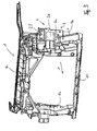
- FIG. 1 recognizes a mounting bracket 1, which in a known manner an upper cross member 1a, a lower cross member 1c and two side support 1b.
- the letter X indicates the vehicle longitudinal direction or direction of travel.
- the connecting sections 2a, 2b, 2c according to the invention are arranged. These are connected to the crash boxes 3, which in turn are connected to the bending beam 4.
- the crash box itself has a direction X or substantially in this direction extending base body 3d, on which the bending beam 4 facing away (viewed in the direction X rear end) a flange plate 3a is provided.
- the flange plate 3a has inter alia abutment sections 3.1, 3.2 for abutment against connecting sections of the mounting bracket 2.
- the mounting bracket is a hybrid component, in which the connecting portions are injected or injected.
- the connection sections have different tasks, but all serve to fix or prefix the crash box (in FIG. 2 not shown).
- a first connecting portion 2a which has an opening 2f, through which a bolt or other fastener can be performed.
- the connecting portion 2a has on its rear side in the direction X on a contact area, to which a contact portion of the crash box can abut, see below.
- a second connecting portion 2b is provided, against which another abutment region of the crash box can rest, either, as shown here, in the direction X in front of the second connecting portion 2b or also (not shown) behind it.
- a third connecting portion 2 c is provided, which is mounted in the example shown on the first connecting portion or formed integrally therewith.
- the third connecting portion 2 c is used in the pre-assembly of the positioning of the crash box, which may be connected to the bending beam 4.
- the contact section of the crash box which is preferably a plate-shaped structure, passes between the first 2a and third connecting section 2c.
- the third connecting portion 2c has a guide portion 2c1 inclined with respect to the direction X.
- the crash box is set in direction Z so that its abutting portion on the abutment surface 2c2 of the third connecting portion 2c comes to lie between the portion 2c1 and the first connecting portion 2a, preferably in a position in which the opening 2f in the first connecting portion coincides with a corresponding one Opening 3e in the contact section 3.1 of the crash box 3 is aligned, so that a fastener can be passed through (see. Fig. 4 ).
- FIG. 4 This situation of pre-assembly of the crash management system or crash boxes 3 on the mounting bracket 1 is in the Figures 3 and 4 shown, wherein the bending beam is not shown.
- the openings 2f and 3e are aligned from the lower abutment section 3.1 and first connecting portion 2a with each other, the same also applies correspondingly to the openings 2e and 3c of the second connecting portion 2b and the upper contact section 3.2.
- a fourth connection portion 2d may be provided at the second connection portion 2b, which conveniently passes through a recess 3b in the upper abutment portion 3.2.
- This fourth connecting portion which may have a screw thread, serves for the provisional fixing of the upper abutment portion 3.1 on the second connecting portion 2b.
- This provisional connection can be realized by a nut, for example, but it is also conceivable that the fourth connection element 2d is formed so that it enters into a resting or snap connection with the section 3.2 when conditioning of section 3.2 and section 3.2.
- the connecting element 2d then has at least one latching lug or the like.
- mounting bracket with pre-assembled crash boxes and bending beams on the vehicle side members of a vehicle can be fixed as a quasi part.
- a large-format flange plate can be dispensed with and there is more space available for other components such as additional stiffeners (for example in the region of the first fastening element 2a) or additional components in the area of the side support 1b.
- the region 2a can be made thicker in the direction X than in conventional mounting supports with flange plates. This applies in principle not only for the Area around 2a below the crash box 3, but also for the area around 2b above the crash box 3.
- the investment area 3.1 not as in FIG. 4 seen in the direction of X provided in front of the second connecting portion 2b, but behind it. In this case, additional space would be available in front of the second connecting portion 2b.
- the gap between the second connecting portion 2 b and the first connecting portion 2 a would then be predetermined only by the width of the base body 3d of the crash box.
Description
Die Erfindung betrifft einen Montageträger für Kraftfahrzeug-Frontends nach dem Oberbegriff des Anspruchs 1.The invention relates to a mounting bracket for motor vehicle front ends according to the preamble of claim 1.
Montageträger der bekannten Art, wie sie z.B. aus
Aufgabe der vorliegenden Erfindung ist es, einen Montageträger der eingangs genannten Art anzugeben, welcher hinsichtlich des zur Anbringung von Crashboxen erforderlichen Bauraumes optimiert ist.Object of the present invention is to provide a mounting bracket of the type mentioned, which is optimized in terms of the installation space required for the attachment of crash boxes.
Gelöst wird diese Aufgabe durch einen Montageträger mit den Merkmalen des Anspruchs 1, vorteilhafte Ausführungsformen finden sich in den Unteransprüchen.This object is achieved by a mounting support with the features of claim 1, advantageous embodiments can be found in the dependent claims.
Der erfindungsgemäße Montageträger weist eine Mehrzahl Verbindungsabschnitte auf, welche unterschiedliche Aufgaben übernehmen. Die "klassische" Flanschplatte wird durch eine Mehrzahl Verbindungsabschnitte ersetzt. Hierdurch wird es möglich, dass die Crashbox mit Hilfe von deren Verbindungsteil bzw. Verbindungsflansch mit den Verbindungsabschnitten des Montageträgers verbunden werden kann, wobei die Crashbox zwischen einzelnen Verbindungsabschnitten hindurchgeführt oder wenigstens einer der Verbindungsabschnitte bei befestigter Crashbox zumindest seitlich des Grundkörpers der Crashbox liegt. Seitlich bedeutet in diesem Fall, dass der betreffende Verbindungsabschnitt auf irgendeine Art neben oder benachbart zum Grundkörper angeordnet sein kann; insbesondere kann der Verbindungsabschnitt oberhalb oder unterhalb wie auch in Fahrzeugquerrichtung rechts oder links des Grundkörpers angeordnet sein. Hierdurch wird erreicht, dass der die Crashbox umgebende Bauraum nicht für das Durchführen der Crashbox-Flanschplatte freigehalten werden muss, sondern anderweitig genutzt werden kann. Die erfindungsgemäßen Verbindungsabschnitte können dabei oberhalb oder/und unterhalb der Crashbox angeordnet sein. Zudem können die Verbindungsabschnitte sowohl auch zur Erhöhung der Steifigkeit etwa mit Rippen oder dergleichen ausgebildet sein, zudem kann ein unterhalb der Crashbox befindlicher Verbindungsabschnitt zur Abstützung und Aufnahme von Kräften eines anliegenden Fußgängerschutzbügels oder dergleichen dienen.The mounting bracket according to the invention has a plurality of connecting portions, which assume different tasks. The "classic" flange plate is replaced by a plurality of connecting sections. This makes it possible that the crash box with the help of their connecting part or connecting flange with can be connected to the connecting portions of the mounting bracket, wherein the crash box passed between individual connection sections or at least one of the connecting sections with attached crash box at least laterally of the main body of the crash box. Laterally means in this case that the relevant connection portion may be arranged in any way next to or adjacent to the base body; In particular, the connecting portion may be arranged above or below as well as in the vehicle transverse direction right or left of the main body. This ensures that the space surrounding the crash box space does not have to be kept free for the implementation of the crash box flange plate, but can be used elsewhere. The connection sections according to the invention can be arranged above and / or below the crash box. In addition, the connecting sections may also be designed to increase rigidity, for example, with ribs or the like; in addition, a connecting section located below the crash box can serve to support and absorb forces of an adjacent pedestrian protection bar or the like.
Erfindungsgemäß weist wenigstens einer der Verbindungsabschnitte eine Öffnung zur Durchführung von Befestigungsmitteln, insbesondere Schrauben, auf. Zwei der Verbindungsabschnitte können bevorzugt miteinander verbunden oder einstückig ausgebildet sein. Bevorzugt ist hierbei, dass der erste Verbindungsabschnitt mit einem dritten Verbindungsabschnitt verbunden und so angeordnet ist, dass der Verbindungsteil der Crashbox zwischen dem ersten und dem dritten Verbindungsabschnitt liegt.According to the invention, at least one of the connecting sections has an opening for the passage of fastening means, in particular screws. Two of the connecting sections may preferably be connected to one another or formed in one piece. In this case, it is preferred that the first connection section is connected to a third connection section and arranged such that the connection part of the crashbox lies between the first and the third connection section.
Bei dieser Ausführungsform gelangen die beiden Verbindungsabschnitte zur Anlage an gegenüberliegenden Seiten der Flanschplatte einer Crashbox, so dass eine einfachere Montage möglich ist und die Einheit aus Crashboxen und Biegeträger sich besser vormontieren lässt.In this embodiment, the two connecting sections come to rest on opposite sides of the flange of a crash box, so that a simpler installation is possible and the unit of crash boxes and bending beams can be better pre-assembled.
Erfindungsgemäß ist vorgesehen, dass ein zweiter Verbindungsabschnitt (entfernt vom ersten Verbindungsabschnitt) vorgesehen ist, so dass die Crashbox zwischen diesen Verbindungsabschnitten liegt. Dabei weist vorteilhafterweise der zweite Verbindungsabschnitt einen vierten Verbindungsabschnitt, insbesondere in Form eines Schraubgewindes, auf. Dies hat den Vorteil, dass die Crashbox am vierten Verbindungsabschnitt nach deren Zusammenfügen mit dem Montageträger vorfixiert werden kann, bevor eine finale Verschraubung von Montageträger, Crashbox und Fahrzeuglängsträger erfolgt.According to the invention, provision is made for a second connecting section (remote from the first connecting section) to be provided, so that the crash box lies between these connecting sections. In this case, advantageously, the second connecting portion has a fourth connecting portion, in particular in the form of a screw thread on. This has the advantage that the crash box can be prefixed on the fourth connecting portion after their assembly with the mounting bracket, before a final screwing of mounting bracket, crash box and vehicle side member is done.
Ferner betrifft die Erfindung ein Kraftfahrzeug-Frontend mit einem Montageträger der oben beschriebenen Art. Das Frontend weist mit dem Montageträger verbundene Crashboxen auf, wobei diese einen sich in Fahrzeuglängsrichtung erstreckenden Grundkörper sowie eine an der Stirnseite des Grundkörpers vorgesehene Flanschplatte aufweisen. Die Flanschplatte weist Anlageabschnitte zur Anlage an entsprechende Verbindungsabschnitte des Montageträgers auf, wobei wenigstens einer der Verbindungsabschnitte seitlich (s.o.) des Grundkörpers angeordnet ist. Bevorzugt ist die Crashbox zwischen zwei Verbindungsabschnitten geführt.The invention further relates to a motor vehicle front end with a mounting bracket of the type described above. The front end has crash boxes connected to the mounting bracket, these having a base body extending in the vehicle longitudinal direction and a flange plate provided on the front side of the main body. The flange plate has abutment portions for abutment with corresponding connecting portions of the mounting bracket, wherein at least one of the connecting portions is arranged laterally (s.o.) of the base body. Preferably, the crash box is guided between two connecting sections.
Weiter ist vorgesehen, , dass wenigstens ein Verbindungsabschnitt des Montageträgers in Fahrzeuglängsrichtung vor und anliegend an einen Anlageabschnitt der Flanschplatte vorgesehen ist. Dabei ist ein zweiter Verbindungsabschnitt des Montageträgers in Fahrzeuglängsrichtung hinter und anliegend an einen Anlageabschnitt der Flanschplatte vorgesehen.It is further provided that at least one connecting portion of the mounting bracket in the vehicle longitudinal direction is provided before and fitting to a contact portion of the flange plate. In this case, a second connecting portion of the mounting bracket is provided in the vehicle longitudinal direction behind and fitting to a contact portion of the flange plate.
Die Erfindung wird nun anhand des Ausführungsbeispiels, welches in den
-
Figur 1 zeigt einen erfindungsgemäßen Montageträger und einen Biegeträger mit Crashboxen in Explosionsdarstellung. -
Figur 2Figur 1 in perspektivischer Ansicht. -
Figur 3 -
Figur 4Figur 3
-
FIG. 1 shows an assembly support according to the invention and a bending beam with crash boxes in an exploded view. -
FIG. 2 shows a section enlargement of the mounting bracketFIG. 1 in perspective view. -
FIG. 3 shows a perspective view of a mounting support according to the invention with crash boxes. -
FIG. 4 shows a section enlargement of the mounting bracketFIG. 3 in perspective view.
In der
Zunächst wird mit Bezug auf
First, with reference to
Der dritte Verbindungsabschnitt 2c dient bei der Vormontage der Positionierung der Crashbox, die mit dem Biegeträger 4 verbunden sein kann. Dabei gelangt der Anlageabschnitt der Crashbox, bei dem es sich bevorzugt um ein plattenförmiges Gebilde handelt, zwischen den ersten 2a und dritten Verbindungsabschnitt 2c. Zur besseren Führung und zum Vereinfachen des Einsetzens der Crashbox an dieser Stelle weist der dritte Verbindungsabschnitt 2c einen gegenüber der Richtung X schräg verlaufenden Führungsabschnitt 2c1 auf. Die Crashbox wird in Richtung Z eingesetzt, so dass ihr Anlageabschnitt auf der Anlagefläche 2c2 des dritten Verbindungsabschnitts 2c zwischen dem Bereich 2c1 und dem ersten Verbindungsabschnitt 2a zu liegen kommt, bevorzugt in einer Position, in der die Öffnung 2f in dem ersten Verbindungsabschnitt mit einer korrespondierenden Öffnung 3e im Anlageabschnitt 3.1 der Crashbox 3 fluchtet, so dass ein Befestigungselement hindurch geführt werden kann (vgl.
Diese Situation der Vormontage des Crashmanagementsystems bzw. der Crashboxen 3 am Montageträger 1 ist in den
So vorfixiert kann dann das Frontend des Fahrzeugs, also Montageträger mit vormontierten Crashboxen und Biegeträger am Fahrzeuglängsträger eines Fahrzeugs quasi als ein Teil befestigt werden.Prefixed so then the front end of the vehicle, so mounting bracket with pre-assembled crash boxes and bending beams on the vehicle side members of a vehicle can be fixed as a quasi part.
Wie insbesondere in
Claims (7)
- Motor vehicle front end with an assembly support member (1), wherein the assembly support member (1) has side supports (1b) and the assembly support member (1) has in the region of the side supports (1b) a connecting means (2) with connecting portions (2a, 2b, 2c, 2d) to connect the assembly support member (1) to a vehicle longitudinal support member and also to a crashbox (3), and also crashboxes (3) connected to the assembly support member (1), wherein the crashboxes (3) have a base body (3d) extending in the vehicle longitudinal direction (X) and a flange plate (3a) provided at the end face of the base body (3d), wherein the flange plate (3a) has abutment portions (3.1, 3.2) for abutment against corresponding connecting portions (2a, 2b, 2c, 2d) of the assembly support member (1),
characterised in that
the connecting portions (2a, 2b, 2c, 2d) are sprayed in or on the assembly support carrier (1) and at least a first (2a) of the connecting portions has an opening (2f) to guide through fixing means, in particular screws, and this is arranged laterally on the base body (3d), wherein the first (2a) of the connecting portions lies in the travel direction (X) before the flange plate (3a) and a further (2b, 2c) of the connecting portions lies in the travel direction (X) behind the flange plate (3a) of the crashbox (3). - Motor vehicle front end according to claim 1,
characterised in that
two of the connecting portions (2a, 2c; 2b, 2d) are connected to each other or integrally formed. - Motor vehicle front end according to claim 2,
characterised in that
the first connecting portion (2a) is connected to a third connecting portion (2c) and is arranged so that the connecting part (3a) of the crashbox (3) lies between the first and the third connecting portion. - Motor vehicle front end according to one of the preceding claims,
characterised in that
the further connecting portion is a second connecting portion (2b) which is provided at a distance from the first connecting portion (2a). - Motor vehicle front end according to claim 4,
characterised in that
the second connecting portion (2b) has a fourth connecting portion (2d), in particular in the form of a screw thread. - Motor vehicle front end according to one of the preceding claims,
characterised in that
at least one connecting portion (2a) of the assembly support member (1) is provided in the vehicle longitudinal direction (X) before and adjacent to an abutment portion (3.1) of the flange plate (3a), wherein at least one second connecting portion (2b, 2c) of the assembly support member (1) is provided in the vehicle longitudinal direction (X) behind and adjacent to an abutment portion (3.1, 3.2) of the flange plate (3a). - Motor vehicle front end according to one of the preceding claims,
characterised in that
the base body (3d) of the crashbox (3) is arranged between at least two connecting portions of the assembly support member.
Applications Claiming Priority (1)
| Application Number | Priority Date | Filing Date | Title |
|---|---|---|---|
| DE102010056065.0A DE102010056065B4 (en) | 2010-12-23 | 2010-12-23 | Motor vehicle front end with a mounting bracket |
Publications (2)
| Publication Number | Publication Date |
|---|---|
| EP2468608A1 EP2468608A1 (en) | 2012-06-27 |
| EP2468608B1 true EP2468608B1 (en) | 2016-01-06 |
Family
ID=45346173
Family Applications (1)
| Application Number | Title | Priority Date | Filing Date |
|---|---|---|---|
| EP11009637.7A Active EP2468608B1 (en) | 2010-12-23 | 2011-12-07 | Assembly support member |
Country Status (4)
| Country | Link |
|---|---|
| EP (1) | EP2468608B1 (en) |
| DE (1) | DE102010056065B4 (en) |
| ES (1) | ES2564798T3 (en) |
| HU (1) | HUE027268T2 (en) |
Families Citing this family (2)
| Publication number | Priority date | Publication date | Assignee | Title |
|---|---|---|---|---|
| US20130134739A1 (en) * | 2011-11-29 | 2013-05-30 | Faurecia Bloc Avant | Motor-vehicle front-face module comprising a flexible zone |
| KR101361268B1 (en) | 2012-12-07 | 2014-02-11 | 현대자동차주식회사 | Front end module for vehicle |
Family Cites Families (5)
| Publication number | Priority date | Publication date | Assignee | Title |
|---|---|---|---|---|
| DE10119114A1 (en) * | 2001-04-19 | 2002-10-24 | Hella Behr Fahrzeugsysteme | Front module with mounting bracket for a motor vehicle |
| DE102004014073B4 (en) * | 2004-03-23 | 2008-09-25 | Hbpo Gmbh | Frontend with mounting bracket |
| DE102004040095B4 (en) | 2004-08-19 | 2007-09-13 | Hbpo Gmbh | Motor vehicle front end |
| DE102005031723B4 (en) | 2005-07-07 | 2010-02-18 | Audi Ag | End part structural element of a motor vehicle made of at least two interconnected support elements |
| DE102009009882B4 (en) | 2009-02-20 | 2022-10-13 | Dr. Ing. H.C. F. Porsche Aktiengesellschaft | Front module for a motor vehicle |
-
2010
- 2010-12-23 DE DE102010056065.0A patent/DE102010056065B4/en not_active Expired - Fee Related
-
2011
- 2011-12-07 ES ES11009637.7T patent/ES2564798T3/en active Active
- 2011-12-07 HU HUE11009637A patent/HUE027268T2/en unknown
- 2011-12-07 EP EP11009637.7A patent/EP2468608B1/en active Active
Also Published As
| Publication number | Publication date |
|---|---|
| ES2564798T3 (en) | 2016-03-29 |
| EP2468608A1 (en) | 2012-06-27 |
| DE102010056065B4 (en) | 2018-03-29 |
| HUE027268T2 (en) | 2016-10-28 |
| DE102010056065A1 (en) | 2012-06-28 |
Similar Documents
| Publication | Publication Date | Title |
|---|---|---|
| EP1669248A2 (en) | Bumper arrangement for a motor vehicle | |
| EP0786398A1 (en) | Motor vehicle with body structure and assembling jig | |
| DE19545069B4 (en) | Bumper with cross member in half shell construction | |
| EP2508407B1 (en) | Frame, in particular for electrical devices in a rail vehicle and method for producing the frame | |
| DE102008013832B4 (en) | Energy absorbing connector | |
| EP3569042B1 (en) | Electronics module, and a mounting base comprising an electronics module | |
| EP2468608B1 (en) | Assembly support member | |
| DE102005049140B4 (en) | Device for attaching a sensor | |
| DE102017009648B4 (en) | Energy storage housing, energy storage arrangement and motor vehicle | |
| WO2021175918A1 (en) | Chassis structure for a vehicle | |
| DE102008060715A1 (en) | Crash box for motor vehicle i.e. passenger car, has fastening units extending as integral component of extruded section in extruding directions, which run transverse and perpendicular to vehicle longitudinal direction | |
| DE102008020051A1 (en) | Crash-box automotive body structure incorporates extruded pressed profile transverse and at right angles to vehicle longitudinal axis | |
| DE102015110436B3 (en) | motor vehicle | |
| EP2840933B1 (en) | Drawer rear wall | |
| DE202016101078U1 (en) | railing | |
| DE60102312T2 (en) | Motor vehicle steering column mounting system | |
| EP2273638A2 (en) | Clip for cable channels for laminating cut edges | |
| DE102007019935A1 (en) | Fixing arrangement has bumper and fender with flange, where fender is locked in assembled condition of bumpers over support beam and bumper is connected with fender by additional connection | |
| DE102019132388B4 (en) | Mounting support for a motor vehicle | |
| EP3466850B1 (en) | Buffer device comprising a stiffening element | |
| EP3566271B1 (en) | Door for an electrical cabinet | |
| EP2982799B1 (en) | Vehicle retention system | |
| EP3067496B1 (en) | Assembly with a fixing device | |
| DE4202443A1 (en) | Snow plough for attachment to front of road vehicle - has share fixed to holder by elastomer blocks and scraper bolted to same blocks | |
| EP0584084B1 (en) | Light-metal casting and process for producing it |
Legal Events
| Date | Code | Title | Description |
|---|---|---|---|
| 17P | Request for examination filed |
Effective date: 20120323 |
|
| AK | Designated contracting states |
Kind code of ref document: A1 Designated state(s): AL AT BE BG CH CY CZ DE DK EE ES FI FR GB GR HR HU IE IS IT LI LT LU LV MC MK MT NL NO PL PT RO RS SE SI SK SM TR |
|
| AX | Request for extension of the european patent |
Extension state: BA ME |
|
| PUAI | Public reference made under article 153(3) epc to a published international application that has entered the european phase |
Free format text: ORIGINAL CODE: 0009012 |
|
| 17Q | First examination report despatched |
Effective date: 20140922 |
|
| GRAP | Despatch of communication of intention to grant a patent |
Free format text: ORIGINAL CODE: EPIDOSNIGR1 |
|
| INTG | Intention to grant announced |
Effective date: 20150804 |
|
| GRAS | Grant fee paid |
Free format text: ORIGINAL CODE: EPIDOSNIGR3 |
|
| GRAP | Despatch of communication of intention to grant a patent |
Free format text: ORIGINAL CODE: EPIDOSNIGR1 |
|
| INTG | Intention to grant announced |
Effective date: 20151106 |
|
| GRAA | (expected) grant |
Free format text: ORIGINAL CODE: 0009210 |
|
| STAA | Information on the status of an ep patent application or granted ep patent |
Free format text: STATUS: THE PATENT HAS BEEN GRANTED |
|
| AK | Designated contracting states |
Kind code of ref document: B1 Designated state(s): AL AT BE BG CH CY CZ DE DK EE ES FI FR GB GR HR HU IE IS IT LI LT LU LV MC MK MT NL NO PL PT RO RS SE SI SK SM TR |
|
| REG | Reference to a national code |
Ref country code: GB Ref legal event code: FG4D Free format text: NOT ENGLISH |
|
| REG | Reference to a national code |
Ref country code: CH Ref legal event code: EP |
|
| REG | Reference to a national code |
Ref country code: IE Ref legal event code: FG4D Free format text: LANGUAGE OF EP DOCUMENT: GERMAN |
|
| REG | Reference to a national code |
Ref country code: AT Ref legal event code: REF Ref document number: 768592 Country of ref document: AT Kind code of ref document: T Effective date: 20160215 |
|
| REG | Reference to a national code |
Ref country code: DE Ref legal event code: R096 Ref document number: 502011008600 Country of ref document: DE |
|
| REG | Reference to a national code |
Ref country code: ES Ref legal event code: FG2A Ref document number: 2564798 Country of ref document: ES Kind code of ref document: T3 Effective date: 20160329 |
|
| REG | Reference to a national code |
Ref country code: LT Ref legal event code: MG4D |
|
| REG | Reference to a national code |
Ref country code: NL Ref legal event code: MP Effective date: 20160106 |
|
| PG25 | Lapsed in a contracting state [announced via postgrant information from national office to epo] |
Ref country code: NL Free format text: LAPSE BECAUSE OF FAILURE TO SUBMIT A TRANSLATION OF THE DESCRIPTION OR TO PAY THE FEE WITHIN THE PRESCRIBED TIME-LIMIT Effective date: 20160106 |
|
| PG25 | Lapsed in a contracting state [announced via postgrant information from national office to epo] |
Ref country code: FI Free format text: LAPSE BECAUSE OF FAILURE TO SUBMIT A TRANSLATION OF THE DESCRIPTION OR TO PAY THE FEE WITHIN THE PRESCRIBED TIME-LIMIT Effective date: 20160106 Ref country code: NO Free format text: LAPSE BECAUSE OF FAILURE TO SUBMIT A TRANSLATION OF THE DESCRIPTION OR TO PAY THE FEE WITHIN THE PRESCRIBED TIME-LIMIT Effective date: 20160406 Ref country code: IT Free format text: LAPSE BECAUSE OF FAILURE TO SUBMIT A TRANSLATION OF THE DESCRIPTION OR TO PAY THE FEE WITHIN THE PRESCRIBED TIME-LIMIT Effective date: 20160106 Ref country code: HR Free format text: LAPSE BECAUSE OF FAILURE TO SUBMIT A TRANSLATION OF THE DESCRIPTION OR TO PAY THE FEE WITHIN THE PRESCRIBED TIME-LIMIT Effective date: 20160106 Ref country code: GR Free format text: LAPSE BECAUSE OF FAILURE TO SUBMIT A TRANSLATION OF THE DESCRIPTION OR TO PAY THE FEE WITHIN THE PRESCRIBED TIME-LIMIT Effective date: 20160407 |
|
| PG25 | Lapsed in a contracting state [announced via postgrant information from national office to epo] |
Ref country code: PL Free format text: LAPSE BECAUSE OF FAILURE TO SUBMIT A TRANSLATION OF THE DESCRIPTION OR TO PAY THE FEE WITHIN THE PRESCRIBED TIME-LIMIT Effective date: 20160106 Ref country code: LV Free format text: LAPSE BECAUSE OF FAILURE TO SUBMIT A TRANSLATION OF THE DESCRIPTION OR TO PAY THE FEE WITHIN THE PRESCRIBED TIME-LIMIT Effective date: 20160106 Ref country code: PT Free format text: LAPSE BECAUSE OF FAILURE TO SUBMIT A TRANSLATION OF THE DESCRIPTION OR TO PAY THE FEE WITHIN THE PRESCRIBED TIME-LIMIT Effective date: 20160506 Ref country code: RS Free format text: LAPSE BECAUSE OF FAILURE TO SUBMIT A TRANSLATION OF THE DESCRIPTION OR TO PAY THE FEE WITHIN THE PRESCRIBED TIME-LIMIT Effective date: 20160106 Ref country code: SE Free format text: LAPSE BECAUSE OF FAILURE TO SUBMIT A TRANSLATION OF THE DESCRIPTION OR TO PAY THE FEE WITHIN THE PRESCRIBED TIME-LIMIT Effective date: 20160106 Ref country code: LT Free format text: LAPSE BECAUSE OF FAILURE TO SUBMIT A TRANSLATION OF THE DESCRIPTION OR TO PAY THE FEE WITHIN THE PRESCRIBED TIME-LIMIT Effective date: 20160106 Ref country code: IS Free format text: LAPSE BECAUSE OF FAILURE TO SUBMIT A TRANSLATION OF THE DESCRIPTION OR TO PAY THE FEE WITHIN THE PRESCRIBED TIME-LIMIT Effective date: 20160506 |
|
| REG | Reference to a national code |
Ref country code: DE Ref legal event code: R097 Ref document number: 502011008600 Country of ref document: DE |
|
| REG | Reference to a national code |
Ref country code: HU Ref legal event code: AG4A Ref document number: E027268 Country of ref document: HU |
|
| PG25 | Lapsed in a contracting state [announced via postgrant information from national office to epo] |
Ref country code: EE Free format text: LAPSE BECAUSE OF FAILURE TO SUBMIT A TRANSLATION OF THE DESCRIPTION OR TO PAY THE FEE WITHIN THE PRESCRIBED TIME-LIMIT Effective date: 20160106 Ref country code: DK Free format text: LAPSE BECAUSE OF FAILURE TO SUBMIT A TRANSLATION OF THE DESCRIPTION OR TO PAY THE FEE WITHIN THE PRESCRIBED TIME-LIMIT Effective date: 20160106 |
|
| REG | Reference to a national code |
Ref country code: SK Ref legal event code: T3 Ref document number: E 21328 Country of ref document: SK |
|
| PLBE | No opposition filed within time limit |
Free format text: ORIGINAL CODE: 0009261 |
|
| STAA | Information on the status of an ep patent application or granted ep patent |
Free format text: STATUS: NO OPPOSITION FILED WITHIN TIME LIMIT |
|
| PG25 | Lapsed in a contracting state [announced via postgrant information from national office to epo] |
Ref country code: SM Free format text: LAPSE BECAUSE OF FAILURE TO SUBMIT A TRANSLATION OF THE DESCRIPTION OR TO PAY THE FEE WITHIN THE PRESCRIBED TIME-LIMIT Effective date: 20160106 Ref country code: RO Free format text: LAPSE BECAUSE OF FAILURE TO SUBMIT A TRANSLATION OF THE DESCRIPTION OR TO PAY THE FEE WITHIN THE PRESCRIBED TIME-LIMIT Effective date: 20160106 |
|
| REG | Reference to a national code |
Ref country code: FR Ref legal event code: PLFP Year of fee payment: 6 |
|
| 26N | No opposition filed |
Effective date: 20161007 |
|
| PG25 | Lapsed in a contracting state [announced via postgrant information from national office to epo] |
Ref country code: SI Free format text: LAPSE BECAUSE OF FAILURE TO SUBMIT A TRANSLATION OF THE DESCRIPTION OR TO PAY THE FEE WITHIN THE PRESCRIBED TIME-LIMIT Effective date: 20160106 Ref country code: BG Free format text: LAPSE BECAUSE OF FAILURE TO SUBMIT A TRANSLATION OF THE DESCRIPTION OR TO PAY THE FEE WITHIN THE PRESCRIBED TIME-LIMIT Effective date: 20160406 |
|
| PG25 | Lapsed in a contracting state [announced via postgrant information from national office to epo] |
Ref country code: BE Free format text: LAPSE BECAUSE OF NON-PAYMENT OF DUE FEES Effective date: 20161231 |
|
| REG | Reference to a national code |
Ref country code: CH Ref legal event code: PL |
|
| PG25 | Lapsed in a contracting state [announced via postgrant information from national office to epo] |
Ref country code: MC Free format text: LAPSE BECAUSE OF FAILURE TO SUBMIT A TRANSLATION OF THE DESCRIPTION OR TO PAY THE FEE WITHIN THE PRESCRIBED TIME-LIMIT Effective date: 20160106 |
|
| REG | Reference to a national code |
Ref country code: IE Ref legal event code: MM4A |
|
| PG25 | Lapsed in a contracting state [announced via postgrant information from national office to epo] |
Ref country code: CH Free format text: LAPSE BECAUSE OF NON-PAYMENT OF DUE FEES Effective date: 20161231 Ref country code: LU Free format text: LAPSE BECAUSE OF NON-PAYMENT OF DUE FEES Effective date: 20161207 Ref country code: LI Free format text: LAPSE BECAUSE OF NON-PAYMENT OF DUE FEES Effective date: 20161231 |
|
| PG25 | Lapsed in a contracting state [announced via postgrant information from national office to epo] |
Ref country code: IE Free format text: LAPSE BECAUSE OF NON-PAYMENT OF DUE FEES Effective date: 20161207 |
|
| REG | Reference to a national code |
Ref country code: FR Ref legal event code: PLFP Year of fee payment: 7 |
|
| REG | Reference to a national code |
Ref country code: BE Ref legal event code: MM Effective date: 20161231 |
|
| REG | Reference to a national code |
Ref country code: AT Ref legal event code: MM01 Ref document number: 768592 Country of ref document: AT Kind code of ref document: T Effective date: 20161207 |
|
| PGFP | Annual fee paid to national office [announced via postgrant information from national office to epo] |
Ref country code: GB Payment date: 20171204 Year of fee payment: 7 |
|
| PGFP | Annual fee paid to national office [announced via postgrant information from national office to epo] |
Ref country code: ES Payment date: 20180105 Year of fee payment: 7 |
|
| PG25 | Lapsed in a contracting state [announced via postgrant information from national office to epo] |
Ref country code: AT Free format text: LAPSE BECAUSE OF NON-PAYMENT OF DUE FEES Effective date: 20161207 Ref country code: CY Free format text: LAPSE BECAUSE OF FAILURE TO SUBMIT A TRANSLATION OF THE DESCRIPTION OR TO PAY THE FEE WITHIN THE PRESCRIBED TIME-LIMIT Effective date: 20160106 |
|
| PG25 | Lapsed in a contracting state [announced via postgrant information from national office to epo] |
Ref country code: TR Free format text: LAPSE BECAUSE OF FAILURE TO SUBMIT A TRANSLATION OF THE DESCRIPTION OR TO PAY THE FEE WITHIN THE PRESCRIBED TIME-LIMIT Effective date: 20160106 Ref country code: MK Free format text: LAPSE BECAUSE OF FAILURE TO SUBMIT A TRANSLATION OF THE DESCRIPTION OR TO PAY THE FEE WITHIN THE PRESCRIBED TIME-LIMIT Effective date: 20160106 |
|
| PG25 | Lapsed in a contracting state [announced via postgrant information from national office to epo] |
Ref country code: MT Free format text: LAPSE BECAUSE OF FAILURE TO SUBMIT A TRANSLATION OF THE DESCRIPTION OR TO PAY THE FEE WITHIN THE PRESCRIBED TIME-LIMIT Effective date: 20160106 |
|
| PG25 | Lapsed in a contracting state [announced via postgrant information from national office to epo] |
Ref country code: AL Free format text: LAPSE BECAUSE OF FAILURE TO SUBMIT A TRANSLATION OF THE DESCRIPTION OR TO PAY THE FEE WITHIN THE PRESCRIBED TIME-LIMIT Effective date: 20160106 |
|
| GBPC | Gb: european patent ceased through non-payment of renewal fee |
Effective date: 20181207 |
|
| PG25 | Lapsed in a contracting state [announced via postgrant information from national office to epo] |
Ref country code: GB Free format text: LAPSE BECAUSE OF NON-PAYMENT OF DUE FEES Effective date: 20181207 |
|
| REG | Reference to a national code |
Ref country code: ES Ref legal event code: FD2A Effective date: 20200131 |
|
| PG25 | Lapsed in a contracting state [announced via postgrant information from national office to epo] |
Ref country code: ES Free format text: LAPSE BECAUSE OF NON-PAYMENT OF DUE FEES Effective date: 20181208 |
|
| PGFP | Annual fee paid to national office [announced via postgrant information from national office to epo] |
Ref country code: HU Payment date: 20230102 Year of fee payment: 12 |
|
| PGFP | Annual fee paid to national office [announced via postgrant information from national office to epo] |
Ref country code: SK Payment date: 20231229 Year of fee payment: 13 |
|
| PGFP | Annual fee paid to national office [announced via postgrant information from national office to epo] |
Ref country code: FR Payment date: 20231220 Year of fee payment: 13 Ref country code: DE Payment date: 20231201 Year of fee payment: 13 Ref country code: CZ Payment date: 20231222 Year of fee payment: 13 |