EP2468162A2 - Spender - Google Patents
Spender Download PDFInfo
- Publication number
- EP2468162A2 EP2468162A2 EP10810089A EP10810089A EP2468162A2 EP 2468162 A2 EP2468162 A2 EP 2468162A2 EP 10810089 A EP10810089 A EP 10810089A EP 10810089 A EP10810089 A EP 10810089A EP 2468162 A2 EP2468162 A2 EP 2468162A2
- Authority
- EP
- European Patent Office
- Prior art keywords
- paper product
- discharging
- driving shaft
- main body
- body casing
- Prior art date
- Legal status (The legal status is an assumption and is not a legal conclusion. Google has not performed a legal analysis and makes no representation as to the accuracy of the status listed.)
- Withdrawn
Links
- 238000007599 discharging Methods 0.000 claims abstract description 96
- 239000007788 liquid Substances 0.000 claims abstract description 56
- 239000004973 liquid crystal related substance Substances 0.000 claims description 16
- 230000010287 polarization Effects 0.000 claims description 3
- 230000004048 modification Effects 0.000 description 8
- 238000012986 modification Methods 0.000 description 8
- 238000007789 sealing Methods 0.000 description 5
- 230000008878 coupling Effects 0.000 description 3
- 238000010168 coupling process Methods 0.000 description 3
- 238000005859 coupling reaction Methods 0.000 description 3
- 230000000694 effects Effects 0.000 description 3
- 238000000034 method Methods 0.000 description 3
- 239000002304 perfume Substances 0.000 description 3
- 125000003118 aryl group Chemical group 0.000 description 2
- 239000003205 fragrance Substances 0.000 description 2
- 230000005484 gravity Effects 0.000 description 2
- 239000000463 material Substances 0.000 description 2
- QTBSBXVTEAMEQO-UHFFFAOYSA-M Acetate Chemical compound CC([O-])=O QTBSBXVTEAMEQO-UHFFFAOYSA-M 0.000 description 1
- -1 acryl Chemical group 0.000 description 1
- 238000007792 addition Methods 0.000 description 1
- 238000005516 engineering process Methods 0.000 description 1
- 239000011521 glass Substances 0.000 description 1
- 238000001746 injection moulding Methods 0.000 description 1
- 229920003023 plastic Polymers 0.000 description 1
- 239000011347 resin Substances 0.000 description 1
- 229920005989 resin Polymers 0.000 description 1
- 238000006467 substitution reaction Methods 0.000 description 1
- XLYOFNOQVPJJNP-UHFFFAOYSA-N water Substances O XLYOFNOQVPJJNP-UHFFFAOYSA-N 0.000 description 1
Images


Classifications
-
- A—HUMAN NECESSITIES
- A47—FURNITURE; DOMESTIC ARTICLES OR APPLIANCES; COFFEE MILLS; SPICE MILLS; SUCTION CLEANERS IN GENERAL
- A47K—SANITARY EQUIPMENT NOT OTHERWISE PROVIDED FOR; TOILET ACCESSORIES
- A47K10/00—Body-drying implements; Toilet paper; Holders therefor
- A47K10/24—Towel dispensers, e.g. for piled-up or folded textile towels; Toilet paper dispensers; Dispensers for piled-up or folded textile towels provided or not with devices for taking-up soiled towels as far as not mechanically driven
- A47K10/32—Dispensers for paper towels or toilet paper
- A47K10/34—Dispensers for paper towels or toilet paper dispensing from a web, e.g. with mechanical dispensing means
- A47K10/38—Dispensers for paper towels or toilet paper dispensing from a web, e.g. with mechanical dispensing means the web being rolled up with or without tearing edge
- A47K10/3809—Dispensers for paper towels or toilet paper dispensing from a web, e.g. with mechanical dispensing means the web being rolled up with or without tearing edge with roll spindles which are not directly supported
- A47K10/3827—Dispensers for paper towels or toilet paper dispensing from a web, e.g. with mechanical dispensing means the web being rolled up with or without tearing edge with roll spindles which are not directly supported with a distribution opening which is parallel to the rotation axis
-
- A—HUMAN NECESSITIES
- A47—FURNITURE; DOMESTIC ARTICLES OR APPLIANCES; COFFEE MILLS; SPICE MILLS; SUCTION CLEANERS IN GENERAL
- A47K—SANITARY EQUIPMENT NOT OTHERWISE PROVIDED FOR; TOILET ACCESSORIES
- A47K10/00—Body-drying implements; Toilet paper; Holders therefor
- A47K10/24—Towel dispensers, e.g. for piled-up or folded textile towels; Toilet paper dispensers; Dispensers for piled-up or folded textile towels provided or not with devices for taking-up soiled towels as far as not mechanically driven
- A47K10/32—Dispensers for paper towels or toilet paper
- A47K10/34—Dispensers for paper towels or toilet paper dispensing from a web, e.g. with mechanical dispensing means
- A47K10/38—Dispensers for paper towels or toilet paper dispensing from a web, e.g. with mechanical dispensing means the web being rolled up with or without tearing edge
- A47K2010/3881—Dispensers for paper towels or toilet paper dispensing from a web, e.g. with mechanical dispensing means the web being rolled up with or without tearing edge with tearing edges having movable parts
-
- Y—GENERAL TAGGING OF NEW TECHNOLOGICAL DEVELOPMENTS; GENERAL TAGGING OF CROSS-SECTIONAL TECHNOLOGIES SPANNING OVER SEVERAL SECTIONS OF THE IPC; TECHNICAL SUBJECTS COVERED BY FORMER USPC CROSS-REFERENCE ART COLLECTIONS [XRACs] AND DIGESTS
- Y10—TECHNICAL SUBJECTS COVERED BY FORMER USPC
- Y10T—TECHNICAL SUBJECTS COVERED BY FORMER US CLASSIFICATION
- Y10T225/00—Severing by tearing or breaking
- Y10T225/20—Severing by manually forcing against fixed edge
- Y10T225/238—With housing for work supply
Definitions
- the present invention relates to a dispenser for supplying a disposable paper product of a roll type such as a toilet paper, a hand towel and etc. and more particularly to a dispenser having an enhanced structure to enable the paper product to be easily cut with a relatively small force.
- a dispenser which supplies a disposable paper product of a roll type such as a toilet paper, a hand towel and etc.
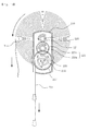
- Fig. 1 is a front sectional view of a conventional dispenser.
- the conventional dispenser 1 has a rotating shaft 13 which is inserted into a through hole 3a of a toilet paper 3 to support it to be rotatable and a discharging part 15 through which the toilet paper 3 is discharged.
- the dispenser 1 has a main body casing 10 which accommodates the toilet paper 3 therein.
- a cutting edge 14 is formed at the discharging part 15 of the main body casing 10 to cut the toilet paper 3.
- an object of the present invention is to provide a dispenser which provides liquid onto an area of a paper product to be cut so that the paper product can be easily cut with a relatively small force.
- the present invention provides a dispenser for supplying a disposable paper product of a roll type comprising: a main body casing which accommodates the paper product and has a rotating shaft supporting the paper product to be rotatable and a discharging part for discharging the paper product, and a wet type cutting unit which is located at the discharging part to provide liquid to a part of the paper product that is to be cut.
- the wet type cutting unit comprises a cutting casing which has a liquid discharging part at a part thereof and a sponge receiving space therein and a pair of guiding parts which extend from the liquid discharging part to have a shape of plates with a predetermined gap therebetween.
- the wet type cutting unit further comprises a sponge unit having a first sponge which is received in the sponge receiving space of the cutting casing and a second sponge which extends from the first sponge and is received between a pair of the guiding parts.
- At least one of the guiding parts has a free end area which is formed with a cutting edge having a shape of a saw or a blade.
- the cutting casing is formed with a liquid inlet for supplying liquid from outside.
- a dispenser for supplying a disposable paper product of a roll type which comprises a main body casing which accommodates the paper product and has a rotating shaft supporting the paper product to be rotatable and a discharging part for discharging the paper product; an elastic discharging unit which has a wire rolled at a side of the main body casing and supplies the paper product by rotating the rotating shaft elastically when the wire is pulled by an outer force; and a wet type cutting unit which is located at the discharging part to provide liquid to a part of the paper product that is to be cut.
- the elastic discharging unit comprises a driving shaft connected with the rotating shaft, an elastic member driving shaft provided apart from the driving shaft, the wire rolled at an end part of the elastic member driving shaft and pulled downward by the outer force, a windup spring wound around the elastic member driving shaft and driving the elastic member driving shaft to rotate if the wire is pulled downward so that the wire can return upward, and a gear train transferring a rotation force due to the windup spring from the elastic member driving shaft to the driving shaft.
- the gear train comprises a first gear coupled to the elastic member driving shaft, a second gear coupled to the driving shaft and a third gear provided between the first gear and the second gear to transfer the rotation force.
- the gear train further comprises a clutch gear which transfers the rotation force from the elastic member driving shaft to the driving shaft only while the wire is being pulled downward.
- the main body casing further comprises a product receiving part which is provided near the discharging part to receive the paper product that is supplied due to a rotation of the driving shaft.
- the main body casing further comprises a discharging guide which is provided at an inside from the discharging part to guide the paper product that is supplied due to a rotation of the driving shaft.
- a dispenser for supplying a disposable paper product of a roll type which comprises a main body casing which accommodates the paper product and has a rotating shaft supporting the paper product to be rotatable and a discharging part for discharging the paper product; an elastic discharging unit which has a wire rolled at a side of the main body casing and supplies the paper product by rotating the rotating shaft elastically when the wire is pulled by an outer force; a wet type cutting unit which is located at the discharging part to provide liquid to a part of the paper product that is to be cut; and a display unit comprising a display panel which is mounted to the main body casing to display letters, pictures or advertisements, a liquid crystal panel which is attached to the display panel to pass or reflect light, a polarization film which is attached to the liquid crystal panel and a power supplying part which supplies an electric power to the liquid crystal panel.
- the main body casing further comprises a product receiving part which is provided near the discharging part to receive the paper product that is supplied due to a rotation of the driving shaft.
- the power supplying part is a solar battery which converts a light energy emitted from a natural light or an illuminating device into an electric energy.
- a dispenser for supplying a disposable paper product of a roll type which comprises a main body casing which accommodates the paper product and has a rotating shaft supporting the paper product to be rotatable and a discharging part for discharging the paper product; an elastic discharging unit which has a wire rolled at a side of the main body casing and supplies the paper product by rotating the rotating shaft elastically when the wire is pulled by an outer force; a wet type cutting unit which is located at the discharging part to provide liquid to a part of the paper product that is to be cut; and a memo board comprising a transparent memo plate which is mounted to the main body casing, an illuminating part which is fixed to an end part of the transparent memo plate to emit light through the transparent memo plate, a power supplying part for supplying an electric power to the illuminating part and a power supplying switch for controlling an electric current applied from the power supplying part.
- a dispenser which provides liquid onto an area of a paper product to be cut so that the paper product can be easily cut with a relatively small force.
- the sponge unit can hold an aroma oil therein to provide a fragrance to a room or to the paper product, so that there is no need of additionally equipping with a perfume or an aromatic.
- a user needs only to pull a wire to a length he or she wants then a rotating shaft is rotated by an elastic force from an elastic member and the paper product is supplied through a discharging part, so that a user's convenience can be enhanced.
- a display unit is provided to a front surface of the dispenser for making the user recognize advertising words or design, so that an advertising effect can be heightened.
- a dispenser 1 for supplying a toilet paper 3 of a roll type is described and drawn as a preferred exemplary embodiment of the present invention.
- the present invention is not limited the dispenser 1 but it may also be applied to various dispensers for supplying a disposable paper product of a roll type such as a hand towel and etc.
- Fig. 2 is an exploded perspective view of a dispenser 1 according to a first exemplary embodiment of the present invention.
- the dispenser 1 according to the first exemplary embodiment of the present invention comprises a main body casing 10 which accommodates a toilet paper 3 and a wet type cutting unit which supplies liquid to the toilet paper 3 discharged from a discharging part 15 of the main body casing 10.
- the main body casing 10 has a rotating shaft 13 which supports the toilet paper 3 to be rotatable and the discharging part 15 through which the toilet paper 3 is discharged.
- the main body casing 10 accommodates the toilet paper 3 therein.
- the main body casing 10 comprises a first main body casing l0a which has a front opening 11 and a second main body casing lOb which covers the front opening 11 of the first main body casing.
- the rotating shaft 13 is located in the first main body casing l0a and the discharging part 15 is formed as an opening under the rotating shaft 13 at a lower end part of the first main body casing 10a.
- a guide rod 17 is located at a center area of the discharging part 15 to be parallel with the rotating shaft 13.
- the guide rod 17 may be injection-molded integrally with the main body casing 10 or may be installed to be rotatable in the main body casing 10.
- the guide rod 17 guides the toilet paper 3 discharged through the discharging part 15 to the center area of the discharging part 15.
- a tension maintaining part 19 may be located in the main body casing 10 to provide tension to the toilet paper 3 thus preventing the toilet paper 3 from being unwound freely.
- the tension maintaining part 19 comprises a tension maintaining shaft 19a which is located at an inner and upper area of the main body casing 10 and extends to be parallel with the rotating shaft 13, and a tension maintain cover 19b which is rotatably coupled to the tension maintaining shaft 19a and has its cross section of an arc shape.
- the tension maintaining shaft 19a When a newly installed toilet paper 3 is inserted by the rotating shaft 13, the tension maintaining shaft 19a is located at an upper area apart from an outer circle of the toilet paper 3. It is preferable that a length of the tension maintaining shaft 19a is the same as or similar to a width of the toilet paper 3.
- the tension maintaining cover 19b is formed to have an arc shape and is rotatable round the tension maintain shaft 19a. It is preferable that a curvature of the tension maintain cover 19b is the same as or similar to that of the outer circle of the newly installed toilet paper 3.
- the tension maintaining cover 19b is installed in a direction where the toilet paper 3 is unwound. Therefore, even if an outer diameter is getting smaller while the toilet paper 3 is being used, the tension maintaining cover 19b is rotated around the tension maintaining shaft 19a by gravity so that it can press the toilet paper 3.
- Such a structure of the tension maintaining part 19 can be found in a conventional toilet paper holder.
- the structure of the tension maintaining part 19 can also be adopted from various structures of conventional holders for a roll type toilet paper.
- a mounting part 70 where the wet type cutting unit 20 is mounted is formed at an inner surface of the first main body casing 10a to be near to the discharging part 15.
- Fig. 3 is an exploded perspective view of the wet type cutting unit 20 of the dispenser 1 according to the first exemplary embodiment of the present invention.
- Fig. 5 is a sectional view of the wet type cutting unit 20 of the dispenser 1.
- the wet type cutting unit 20 is provided to the discharging part 15 and supplies liquid to an area of the toilet paper 3 to be cut.
- the wet type cutting unit 20 has a cutting casing 30 and a pair of guiding parts 40.
- the cutting casing 30 has a liquid discharging part 31 at a side part thereof and a sponge receiving space 33 therein.
- the cutting casing 30 may comprise a first cutting casing 30a and a second cutting casing 30b which are provided to be attached and detached therebetween to open or close the sponge receiving space 33.
- the cutting casing 30 is formed as a box of a roughly rectangular shape in this exemplary embodiment, it is not limited regarding its shape as long as the sponge receiving space 33 is formed therein.
- the first cutting casing 30a and the second cutting casing 30b are coupled together with a hinge.
- a hinge part 35 is provided between the first cutting casing 30a and the second cutting casing 30b.
- the hinge part 35 is located at the opposite side of the liquid discharging part 31.
- the hinge part 35 comprises a hinge shaft 35a and a hinge shaft receiving part 35b.
- the hinge shaft 35a may be provided as a rod or a screw.
- first cutting casing 30a and the second cutting casing 30b are described to be coupled therebetween with the hinge part 35, the present invention is lot limited to the description and the first and the second cutting casings 30a, 30b may also be coupled therebetween through inserting or fastening with hooks, rivets or screws.
- the liquid discharging part 31 is formed as an opening at a side part of the cutting casing 30.
- the liquid discharging part 31 is formed as an elongated hole in a direction along a width of the toilet paper 3. It is preferable that a length of the elongated hole is the same as or similar to the width of the toilet paper 3.
- a pair of the guiding parts 40 extend from both sides of the liquid discharging part 31 with a predetermined gap d therebetween.
- the guiding parts 40 extend from the first cutting casing 30a and the second cutting casing 30b at the liquid discharging part 31 to be provided as plates parallel therebetween with the gap d.
- a pair of the guiding parts 40 are locked or unlocked therebetween by a locking part 45.
- the locking part 45 comprises a locking protrusion 45a and a locking protrusion receiving part 45b which are coupled therebetween by the relative rotation of the first cutting casing 30a to the second cutting casing 30b.
- the locking protrusion 45a and the locking protrusion receiving part 45b are coupled together in a forced inserting manner to maintain a coupling force therebetween.
- the locking part 45 may be provided as fastening means such as screws, rivets, pins and etc.
- the dispenser 1 may further comprise a sealing member 50 which seals a coupling area between the first cutting casing 30a and the second cutting casing 30b.
- the sealing member 50 is provided as a shape of a line which is disposed along a border area of the first and the second cutting casings 30a and 30b.
- the sealing member 50 is preferably made of a rubber. Also, the sealing member 50 is provided as an O-ring or a gasket.
- the sealing member 50 is formed as a shape of " ⁇ " to be installed along the border area of the first and the second cutting casings 30a, 30b excluding the liquid discharging part 31.
- the wet type cutting unit 20 may further comprise a sponge unit 60 having a first sponge 60a which is received in the sponge receiving space 33 of the cutting casing 30 and a second sponge 60b which extends from the first sponge 60a to be received between a pair of the guiding parts 40.
- the first sponge 60a holds the liquid relatively more than the second sponge 60b can hold.
- the second sponge 60b protrudes from the first sponge 60a to be received between a pair of the guiding parts 40.
- the second sponge 60b is located lower than the first sponge 60a.
- the liquid in the first sponge 60a moves towards the second sponge 60b by gravity, so that the second sponge 60b can hold a relatively more liquid.
- the second sponge 60b can always hold the liquid as long as the sponge unit 60 is not dried out.
- the second sponge 60b is provided to have the same length as or to be longer than the guiding part 40.
- the second sponge 60b protrudes from the first sponge 60a and extends to an end part of a blade 41 which is described later. Or, the second sponge 60b extends further to be exposed to an outside.
- the toilet paper 3 can directly contact the second sponge 60b to be supplied with the liquid.
- the sponge unit 60 may be a conventional sponge that is widely used or may be made of acetate tow.
- the liquid supplied to the sponge unit 60 may be a fragrant liquid such as aroma oil, perfume or etc as well as water.
- a fragrance can be provided by the aroma oil held in the sponge unit 60 when there is no perfume or aromatic that needs to be additionally equipped.
- At least one of the guiding parts 40 may have a free end area which is formed with a cutting edge 41 having a shape of a saw.
- the cutting edge 41 is formed at both of the guiding parts 40 in this exemplary embodiment, it may also be formed at only one of the guiding parts 40.
- the cutting edge 41 may have a shape of a saw as shown in Fig. 3 or a shape of a blade as shown in Fig. 4 .
- Such a cutting edge 41 may be made of the same material as the cutting casing 30 or injection-molded integrally.
- the cutting edge 41 may be made of a material different from that of the cutting casing 30 and inserted when injection-molding the cutting casing 30.
- a first liquid inlet 80a may be formed at the cutting casing 30 to supply the liquid from outside.
- a second liquid inlet 80b is formed at the main body casing 10 to correspond to the first liquid inlet 80a.
- a user can supply the liquid to the sponge unit 60 through the first liquid inlet 80a and the second liquid inlet 80b by using an injecting device 5 such as a syringe.
- first and the second liquid inlets 80a and 80b are described and drawn as means for supplying the liquid into the cutting casing, the present invention is not limited to such means but may be have the cutting casing 30 provided with a cap or plug installed on a surface for opening an inside of the cutting casing 30.
- the user can supply the liquid into the cutting casing 30 by operating the cap or the plug.
- the wet type cutting unit 20 may be provided to be detachable from the main body casing 10.
- the mounting part 70 is formed on an inner surface of the first main body casing 10a near the discharging part 15 for mounting the wet type cutting unit 20.
- the wet type cutting unit 20 is inserted into such a mounting part 70.
- the user can separate the wet type cutting unit 20 from the main body casing 10 to charge the liquid.
- the wet type cutting unit 20 is drawn to be inserted into the mounting part 70 in an axial direction of the rotating shaft 13, the mounting part 70 may also be provide such that the wet type cutting unit 20 is inserted in a rotational direction of the toilet paper 3.
- wet type cutting unit 20 may be mounted to the main body casing 10 with a hook or through an adhering means such as a double-sided tape, Velcro and etc.
- the wet type cutting unit 20 is provide at both sides of the discharging part 20, it may also be provided at only one side of the discharging part 15.
- the dispenser 1 for supplying the toilet paper 1 is described, the present invention is not limited to this but may be applicable to various dispensers for supplying a disposable paper product of a roll type such as a hand towel and etc.
- Figs. 7 and 8 are sectional views showing the operating process of the dispenser 1 according to the first exemplary embodiment of the present invention.
- the liquid is charged enough in the sponge unit 60 and the toilet paper 3 is accommodated in the main body casing 10.
- the liquid held in the second sponge 60b which is located between a pair of the guiding parts 40 is provided from between a pair of the cutting edges 41 to the toilet paper 3.
- the toilet paper 3 is easily cut at an area where it is provided with the liquid because a tensile strength is weakened at the area.
- the cutting edge 41 presses a vicinity of the area that is provided with the liquid, the user can cut the toilet paper 3 with a less force.
- the user can supply the liquid to the sponge unit 60 through the first and second liquid inlets 80a, 80b by using the inserting device 5 such as a syringe and etc.
- the wet type cutting unit 20 is detachably coupled to the main body casing 10 and the cutting casing 30 is provided to be dividable, the user can separate the wet type cutting unit 20 from the main body casing 10 and easily charge the liquid therein.
- a dispenser 1 can be provided which has a wet type cutting unit 20 provided for supplying liquid to an area of the toilet paper 3 to be cut, so that the toilet paper 3 can be easily cut with a relatively small force.
- Fig. 9 is a front view of the dispenser 1 according to the second exemplary embodiment of the present invention
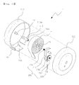
- Fig. 10 is an exploded perspective view of the dispenser 1 according to the second exemplary embodiment of the present invention
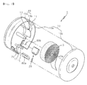
- Fig. 11 is an exploded perspective view of an elastic discharging unit 200 of Fig. 10 .
- the dispenser 1 comprises a main body casing 100 which accommodates a paper product T and the elastic discharging unit 200 which is installed in the main body casing 100 and enables the paper product T to be supplied automatically when a wire 231 is pulled.
- the main body casing 100 comprises a first casing 110 and a second casing 120.
- the first casing 110 has a shape of a case with a front opening and accommodates the paper product T therein.
- the second casing 120 is coupled to the first casing 110 to cover the front opening of the first casing 110.
- the elastic discharging unit 200 is coupled to the second casing 120.
- the first casing 110 has a supporting rib 111 which supports a rotating shaft 115 to be rotatable and the rotating shaft 115 which is supported by the supporting rib 111 at one end and is coupled to a driving shaft 220 of the elastic discharging unit 200 at the other end.
- the rotating shaft 115 is inserted in a shaft hole Ta of the paper product T.
- a discharging part 130 where the paper product T is discharged is formed at a lower end part of the first casing 110.
- a cutting edge 140 is formed at both sides of the discharging part 130.
- a product receiving part 150 is provided to receive therein the paper product T discharged through the discharging part 130.
- the supporting rib 111 protrudes from an inner surface of the first casing 110 to rotatably support the rotating shaft 115.
- the supporting rib 111 is inserted into a rib receiving hole 115a of the rotating shaft 115.
- the rotating shaft 115 is coupled to the driving shaft 220 and is rotated in the first casing 110 according to a rotation of the driving shaft 220.
- the rotating shaft is inserted in the shaft hole Ta of the paper product T and rotates the paper product T to be supplied to the discharging part 130.
- the rotating shaft 115 has at one end a rib receiving hole 115 to receive the supporting rib 111 and at the other end a driving shaft receiving hole 115b to be coupled to the driving shaft 220.
- the cutting edge 140 is provided at both sides of the discharging part 130 to enable a user to cut the paper product T discharged through the discharging part 130.
- the product receiving part 150 is located at a lower side of the discharging part 130 and is provided to surround the discharging part 130 in part.
- the product receiving part 150 covers a lower area of the discharging part 130 to receive therein the paper product T which is automatically supplied with a predetermined length by the wire 231.
- the product receiving part 150 may be integrally provided with the first casing 110 or may be detachably attached to the first casing 110.
- the second casing 120 covers and closes the front opening of the first casing 110.
- the elastic discharging unit 200 is coupled to the second casing 120.
- the second casing 120 has a wire withdrawing hole 121 to withdraw the wire 231 of the elastic discharging unit 200 to an outside.
- the wire 231 is exposed to a predetermined length downward from the wire withdrawing hole 121 to enable the user to pull.
- the elastic discharging unit 200 is coupled to the second casing 120 and enables the rotating shaft 115 to rotate thus supplying the paper product T through the discharging part 130 to a predetermined length the user needs as much as he/she pulls the wire 231.
- the elastic discharging unit 200 comprises a casing 210 received in the second casing 120, the driving shaft 220 disposed in the casing 210 and coupled to the rotating shaft 115, an elastic member driving shaft 230 disposed apart from the driving shaft 220 to a predetermined distance and coupled to an elastic member 233, the elastic member 233 and a wire 231 both coupled to the elastic member driving shaft 230, and a gear train 221, 223, 237 and a clutch gear 235 for transferring a rotation of the elastic member driving shaft 230 to the driving shaft 220.
- the casing 210 comprises a front casing 211 and a rear casing 213 coupled therebetween.
- the driving shaft 220 is coupled to the front casing 211 and the rear casing 213 to be rotatable and is fixedly coupled to the rotating shaft 115 through the front casing 211.
- a second transfer gear 221 is coupled to the driving shaft 220 to transfer a rotation force from the elastic member driving shaft 230 to the driving shaft 220.
- the elastic member driving shaft 230 is located apart from the driving shaft 220 to a predetermined distance and has a part where the elastic member 233 wound and another part where the wire 231 is wound.
- the elastic member driving shaft 230 is rotatably coupled to the front casing 211 and the rear casing 213.
- the elastic member 233 is coupled to the elastic member driving shaft 230.
- an inner end part 233a of the elastic member 233 is inserted into an elastic member coupling hole 230b.
- the elastic member 233 is provided as a windup spring that is wound to several turns around the elastic member driving shaft 230.
- the wire 231 is wound around an end part of the elastic member driving shaft 230 which is exposed at an outside of the rear casing 213.
- a wire supporting plate 232 is coupled to an end part of the elastic member driving shaft 230.
- the wire supporting plate 232 has an outer circumference of a 'U' shape to hold and support the wire 231 around the elastic member driving shaft 230.
- Teeth 230a are formed on a round surface of the elastic member driving shaft 230 in an axial direction and coupled to grooves 232a formed on an inner surface of a shaft hole of the wire supporting plate 232.
- the elastic member driving shaft 230 is rotated integrally with the wire supporting plate 232.
- a clutch gear 235 is provided to the elastic member driving shaft 230.
- the clutch gear 235 is a shaft connecting means for connecting or disconnecting a driving force between shafts.
- the clutch gear 235 enables the rotating force to be transferred to the driving shaft 220 when the elastic member driving shaft 230 is rotated in a direction where the user pulls the wire 231 downward.
- the clutch gear 235 prevents the rotating force from being transferred to the driving shaft 220.
- the clutch gear 235 is engaged to an inner gear 237b of a first gear 237 to perform transferring the rotating force in one direction.
- the first gear 237 is rotatably supported by the elastic member driving shaft 230 to transfer the rotating force from the elastic member driving shaft 230 to a second gear 221.
- the first gear 237 has an outer gear 237a formed on an outer circumference and the inner gear 237b formed in an inner side of the outer gear 237a.
- the outer gear 237a is engaged to a smaller gear 223a of a third gear 223 to transfer the rotating force according to a rotation of the elastic member driving shaft 230.
- the inner gear 237b is engaged to the clutch gear 235 and transfers the rotating force to the second gear 221 only when the elastic member driving shaft 230 is rotated in a direction where the wire 231 is lowered.
- the third gear 223 is provided between the first gear 237 and the second gear 221 to transfer the rotating force from the elastic member driving shaft 230 to the driving shaft 220.
- the third gear 223 is coupled to a third gear supporting shaft 224 which is rotatably supported by the front casing 211 and the rear casing 213.
- the third gear 223 comprises the smaller gear 223a and a bigger gear 223b which have the same axis of rotation.
- the smaller gear 223a is engaged to the first gear 237 and the bigger gear 223b is engaged to the second gear 221.
- the user who needs the paper product T pulls down the wire 231 which is exposed under the main body casing 100.
- the elastic member driving shaft 230 is rotated in a direction in which the wire 231 is unwound.
- the elastic member driving shaft 230 is rotated in the direction where the wire 231 is unwound, the elastic member 233 which has been fixed to the elastic member driving shaft 230 is rotated in a direction in which it is wound around the elastic member driving shaft 230 further than it is in an initial state.
- the smaller gear 223a and the bigger gear 223b of the third gear 223 are rotated together.
- the rotating shaft 115 to which the paper product T is coupled is rotated.
- the paper product T Due to the rotation of the rotating shaft 115, the paper product T is unwound and discharged through the discharging part 130. The discharged paper product T is received into the product receiving part 150.
- the elastic member 23 is unwound elastically to return to its initial state while the wire 231 is raised up.
- the elastic member driving shaft 230 and the clutch gear 235 which is integrally coupled to the elastic member driving shaft 230 are rotated together.
- the first gear 237 which is coupled to the clutch gear 235 in one direction is not rotated.
- the rotating shaft is rotated by the elastic force of the elastic member to discharge the paper product T through the discharging part, so that the user's convenience can be enhanced.
- Fig. 14 is a front view of a modification of the dispenser according to the second exemplary embodiment of the present invention.
- the dispenser 1 includes at its discharging part 130 a wet type cutting unit 20 which supplies liquid to an area of the paper product T to cut.
- the wet type cutting unit 20 comprises a sponge 60, a cutting casing 30, a cutting guide 40 and etc. which are the same as those in the exemplary embodiment of the present invention and whose detailed descriptions are omitted here.
- the dispenser 1 if the paper product is automatically supplied to a predetermined length by the wire and received in the product receiving part 150, the user contacts the area to cut in the paper product onto the cutting guide 40 of the wet type cutting unit 20.
- a discharging guide 160 is located in the main body casing 100 at an inner side of the discharging part 130.
- the discharging guide 160 guides the paper product T which is supplied by the rotation of the driving shaft 220 as described above to be easily discharged through the discharging part 130.
- the discharging guide 160 prevents the paper product T from being not unrolled due to an excessive rotation speed of the driving shaft 220.
- Fig. 15 is a perspective view of another modification of the dispenser according to the second exemplary embodiment of the present invention, where a display unit 400 is provided in the dispenser 1.
- the display unit 400 is mounted on a front surface of the main body casing 100 to make the user recognize an advertisement phrase or design thus improving an advertising effect.
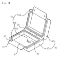
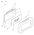
- Fig. 16 is an exploded perspective view of the display unit 400 of the dispenser 1 of Fig. 15 .
- the display unit 400 comprises a display panel 420 which displays letters, pictures or advertisements and liquid crystal panel 430 which is attached to the display panel 420 to pass or reflect light and a power supplying part 410 which supplies an electric power to the liquid crystal panel 430.
- the power supplying part 410 is a solar battery.
- the liquid crystal panel 430 is divided into a plurality of sectors 431 in front of the display panel 420 and a polarization film is attached to the liquid crystal panel 430 to protect the liquid crystal panel 430 and to polarize light.
- a solar battery mounting part 412 is provided on an upper side of the display unit 400.
- the solar battery 410 which is mounted in the solar battery mounting part 412 supplies electric power to the liquid crystal panel 430.
- the solar battery 410 is a device which converts light energy emitted from a natural light or an illuminating device into an electric energy, so that it supplies the electric power for driving the liquid crystal panel 430.
- the electric energy generated by the solar battery 410 is controlled by a control chip on a board 411 which is connected to the liquid crystal panel 430.
- the liquid crystal panel 430 turns on and off sequentially among the sectors 431 to make the user clearly recognize a mark 421.
- liquid crystal panel 430 and the display panel 420 are driven only by the solar battery 410.
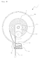
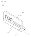
- the display unit 400 described above may be substituted by a memo board 500 shown in Fig. 17 .
- the memo board 500 is provided to display an advertising phrase or design thereon.
- the memo board 500 to be mounted to the main body casing 100 comprises a transparent memo plate 510 which displays the advertising phrase or design thereon, an illuminating part 520 which is fixed to an end part of the transparent memo plate 510 to emit light through the transparent memo plate 510, a power supplying part 530 for supplying an electric power to the illuminating part 520 and a power supplying switch 540 for controlling an electric current applied from the power supplying part 530.
- the transparent memo plate 510 is made of transparent plastics such as acryl resin or glass having a predetermined thickness.
- the illuminating part 520 is fixed to a lower end part of the transparent memo plate 510 and has an LED (light emitting diode) therein to illuminate the transparent memo plate 510 at its upper side when it is turned on by the power supplying switch 540.
- the power supplying part 230 is provided at a rear side of the illuminating part 520 and has therein a plurality of batteries 531 as a power source of the LED.
- a receiving part 532 to receive the batteries 531 and a cover 533 to cover the receiving part 532.
- the memo board 500 may always be in an 'ON' state for a convenience in use to enable the advertising phrase or design to be easily recognized even in the dark.
Landscapes
- Health & Medical Sciences (AREA)
- Public Health (AREA)
- Unwinding Webs (AREA)
- Details Of Rigid Or Semi-Rigid Containers (AREA)
Applications Claiming Priority (4)
| Application Number | Priority Date | Filing Date | Title |
|---|---|---|---|
| KR2020090010950U KR200458150Y1 (ko) | 2009-08-21 | 2009-08-21 | 디스펜서 |
| KR20090082934 | 2009-09-03 | ||
| KR1020100042370A KR101105553B1 (ko) | 2010-05-06 | 2010-05-06 | 디스펜서 |
| PCT/KR2010/004721 WO2011021781A2 (ko) | 2009-08-21 | 2010-07-20 | 디스펜서 |
Publications (2)
| Publication Number | Publication Date |
|---|---|
| EP2468162A2 true EP2468162A2 (de) | 2012-06-27 |
| EP2468162A4 EP2468162A4 (de) | 2017-01-11 |
Family
ID=43607427
Family Applications (1)
| Application Number | Title | Priority Date | Filing Date |
|---|---|---|---|
| EP10810089.2A Withdrawn EP2468162A4 (de) | 2009-08-21 | 2010-07-20 | Spender |
Country Status (5)
| Country | Link |
|---|---|
| US (1) | US8960514B2 (de) |
| EP (1) | EP2468162A4 (de) |
| JP (1) | JP3177666U (de) |
| CN (1) | CN102481074B (de) |
| WO (1) | WO2011021781A2 (de) |
Families Citing this family (9)
| Publication number | Priority date | Publication date | Assignee | Title |
|---|---|---|---|---|
| US9809439B2 (en) | 2014-09-08 | 2017-11-07 | Ernest F. FALCO, III | Sanitary touch-free automatic condiment dispensing apparatus and method of use |
| US9772078B2 (en) | 2015-08-27 | 2017-09-26 | Timothy Suggs | Lighted toilet paper holder |
| US9957125B2 (en) | 2016-02-04 | 2018-05-01 | Ilya Ray | Sanitary automatic glove dispensing apparatus and method of use |
| US11155401B2 (en) | 2016-02-04 | 2021-10-26 | Ilya Ray | Sanitary glove dispensing apparatus |
| US12268341B2 (en) * | 2018-05-24 | 2025-04-08 | Charles Agnew Osborne, Jr. | Sheet material dispensing assembly with integrated gear clutch |
| WO2019241387A1 (en) * | 2018-06-14 | 2019-12-19 | Smith & Nephew, Inc. | Weightless traction system |
| US10800587B2 (en) * | 2018-06-29 | 2020-10-13 | Henkel IP & Holding GmbH | Separatable agent doses |
| US11542460B2 (en) | 2021-04-14 | 2023-01-03 | Henkel Ag & Co. Kgaa | Multi-chamber detergent single dose packs with detachable and reattachable functionality and methods of using the same |
| CN118789135B (zh) * | 2024-08-14 | 2025-03-18 | 深圳市兴益鑫科技有限公司 | 一种纸张生产用纸张激光切割机 |
Family Cites Families (22)
| Publication number | Priority date | Publication date | Assignee | Title |
|---|---|---|---|---|
| US2560065A (en) * | 1950-01-21 | 1951-07-10 | Avrick Abraham | Sealing machine attachment for gummed tape dispensers |
| KR900000262B1 (ko) * | 1987-04-04 | 1990-01-24 | 이중재 | 유압브레이크시스템을 이용한 자동차 논슬립제어장치 |
| KR900000262Y1 (ko) * | 1987-12-28 | 1990-01-30 | 박정극 | 쪽 가위 |
| KR910003589Y1 (ko) * | 1988-06-11 | 1991-05-31 | 전성조 | 화장지 배출기 |
| JPH03149818A (ja) | 1989-11-06 | 1991-06-26 | Mitsubishi Electric Corp | 半導体装置およびその製造方法 |
| CN2089311U (zh) * | 1991-03-16 | 1991-11-27 | 仝利民 | 单手可取任意长短的卫生纸盒 |
| JPH06269374A (ja) * | 1993-03-17 | 1994-09-27 | Fushimi Seiyakushiyo:Kk | 使い捨て殺菌タオルのディスペンサ |
| DE29501934U1 (de) * | 1995-02-07 | 1995-06-08 | Loos, Harry, 71287 Weissach | Wandspender für Intensiv-Feucht-Reinigungstücher |
| US6098917A (en) * | 1996-04-26 | 2000-08-08 | Cruz; Joseph P. | Hands-free paper towel dispenser |
| JP3149818B2 (ja) | 1997-06-02 | 2001-03-26 | 住友金属工業株式会社 | 連続鋳造による丸ビレット鋳片の製造方法 |
| JP2002272636A (ja) * | 2001-03-21 | 2002-09-24 | Takayuki Onodera | 片手操作用ペーパーホルダー。 |
| JP3761853B2 (ja) * | 2001-11-01 | 2006-03-29 | 敏治 平井 | ペーパーホルダー及びペーパー切断装置 |
| CN2514777Y (zh) * | 2001-12-20 | 2002-10-09 | 林万荣 | 卫生纸全自动供应装置 |
| US7289179B2 (en) * | 2002-11-08 | 2007-10-30 | Samsung Electronics Co., Ltd. | Liquid crystal display |
| US7101441B2 (en) * | 2003-03-02 | 2006-09-05 | Kennard Wayne M | Toilet paper dispenser |
| US7726599B2 (en) * | 2003-12-31 | 2010-06-01 | Kimberly-Clark Worldwide, Inc. | Apparatus and method for dispensing sheet material |
| US7213782B2 (en) * | 2004-01-30 | 2007-05-08 | Charles Agnew Osborne | Intelligent dispensing system |
| JP2005245647A (ja) * | 2004-03-03 | 2005-09-15 | Yoshino Kinzoku Co Ltd | ペーパーホルダー |
| US20070272701A1 (en) * | 2004-03-12 | 2007-11-29 | Rickard Carlsson | Paper dispenser |
| KR100643196B1 (ko) | 2004-10-28 | 2006-11-10 | (주) 폭스힐 | 액정패널을 이용한 광고장치 |
| KR101321659B1 (ko) * | 2007-06-28 | 2013-10-22 | 주식회사 엘지생활건강 | 화장품 용기 |
| US8600547B2 (en) * | 2008-08-22 | 2013-12-03 | Georgia-Pacific Consumer Products Lp | Sheet product dispenser and method of operation |
-
2010
- 2010-07-20 JP JP2012600035U patent/JP3177666U/ja not_active Expired - Fee Related
- 2010-07-20 EP EP10810089.2A patent/EP2468162A4/de not_active Withdrawn
- 2010-07-20 US US13/389,785 patent/US8960514B2/en not_active Expired - Fee Related
- 2010-07-20 CN CN201080037154.8A patent/CN102481074B/zh not_active Expired - Fee Related
- 2010-07-20 WO PCT/KR2010/004721 patent/WO2011021781A2/ko not_active Ceased
Non-Patent Citations (1)
| Title |
|---|
| See references of WO2011021781A2 * |
Also Published As
| Publication number | Publication date |
|---|---|
| US20120138654A1 (en) | 2012-06-07 |
| JP3177666U (ja) | 2012-08-16 |
| EP2468162A4 (de) | 2017-01-11 |
| WO2011021781A2 (ko) | 2011-02-24 |
| CN102481074A (zh) | 2012-05-30 |
| US8960514B2 (en) | 2015-02-24 |
| WO2011021781A3 (ko) | 2011-04-21 |
| CN102481074B (zh) | 2014-12-31 |
Similar Documents
| Publication | Publication Date | Title |
|---|---|---|
| US8960514B2 (en) | Dispenser | |
| EP2214542B1 (de) | Elektromanueller spender | |
| US20070193426A1 (en) | Adhesive tape dispenser | |
| US7540225B2 (en) | Double-faced adhesive tape dispenser | |
| KR20100031660A (ko) | 표지를 선택적으로 나타내기 위한 시스템 | |
| KR101105553B1 (ko) | 디스펜서 | |
| WO2005013244A3 (en) | Retractable display apparatus | |
| US9514662B2 (en) | System for selectively revealing indicia | |
| CN216509363U (zh) | 贴膜工具和贴膜组件 | |
| CN210297894U (zh) | 一种直下式背光电视机 | |
| KR101996365B1 (ko) | 사용편의성이 향상된 접착테이프 케이스 | |
| KR200458150Y1 (ko) | 디스펜서 | |
| TWI243045B (en) | Roller type wiping paper supplying device | |
| CN210191351U (zh) | 一种可发光的车载纸巾盒 | |
| CN212450119U (zh) | 一种条幅收卷展示装置 | |
| JP4064737B2 (ja) | ディスペンサ内のトイレットペーパー又はハンドタオルの交換時期表示装置 | |
| KR20230087949A (ko) | 절약형 화장지 디스펜서 | |
| JP2006142519A (ja) | 携帯型プリンタ | |
| KR200408618Y1 (ko) | 휴대용 명함식 치실 케이스 | |
| KR200449286Y1 (ko) | 광고 효과를 갖는 두루마리 휴지 걸이 | |
| WO2014011602A1 (en) | System for selectively revealing indicia |
Legal Events
| Date | Code | Title | Description |
|---|---|---|---|
| PUAI | Public reference made under article 153(3) epc to a published international application that has entered the european phase |
Free format text: ORIGINAL CODE: 0009012 |
|
| 17P | Request for examination filed |
Effective date: 20120320 |
|
| AK | Designated contracting states |
Kind code of ref document: A2 Designated state(s): AL AT BE BG CH CY CZ DE DK EE ES FI FR GB GR HR HU IE IS IT LI LT LU LV MC MK MT NL NO PL PT RO SE SI SK SM TR |
|
| DAX | Request for extension of the european patent (deleted) | ||
| RIC1 | Information provided on ipc code assigned before grant |
Ipc: A47K 10/38 20060101AFI20160523BHEP Ipc: A47K 10/36 20060101ALI20160523BHEP |
|
| RIC1 | Information provided on ipc code assigned before grant |
Ipc: A47K 10/38 20060101AFI20160909BHEP Ipc: A47K 10/36 20060101ALI20160909BHEP |
|
| R17P | Request for examination filed (corrected) |
Effective date: 20120320 |
|
| RIC1 | Information provided on ipc code assigned before grant |
Ipc: A47K 10/36 20060101ALI20161012BHEP Ipc: A47K 10/38 20060101AFI20161012BHEP |
|
| A4 | Supplementary search report drawn up and despatched |
Effective date: 20161212 |
|
| RIC1 | Information provided on ipc code assigned before grant |
Ipc: A47K 10/36 20060101ALI20161206BHEP Ipc: A47K 10/38 20060101AFI20161206BHEP |
|
| STAA | Information on the status of an ep patent application or granted ep patent |
Free format text: STATUS: THE APPLICATION IS DEEMED TO BE WITHDRAWN |
|
| 18D | Application deemed to be withdrawn |
Effective date: 20170201 |