EP2467754B1 - Manipulateur de lumière transportable - Google Patents
Manipulateur de lumière transportable Download PDFInfo
- Publication number
- EP2467754B1 EP2467754B1 EP10730765.4A EP10730765A EP2467754B1 EP 2467754 B1 EP2467754 B1 EP 2467754B1 EP 10730765 A EP10730765 A EP 10730765A EP 2467754 B1 EP2467754 B1 EP 2467754B1
- Authority
- EP
- European Patent Office
- Prior art keywords
- portable light
- cloth
- frame
- longitudinal
- manipulator
- Prior art date
- Legal status (The legal status is an assumption and is not a legal conclusion. Google has not performed a legal analysis and makes no representation as to the accuracy of the status listed.)
- Not-in-force
Links
- 239000004744 fabric Substances 0.000 claims description 66
- 230000006835 compression Effects 0.000 claims description 7
- 238000007906 compression Methods 0.000 claims description 7
- 230000000284 resting effect Effects 0.000 claims 1
- 238000006073 displacement reaction Methods 0.000 description 62
- 238000010276 construction Methods 0.000 description 6
- 239000000463 material Substances 0.000 description 4
- 230000008901 benefit Effects 0.000 description 3
- 230000003993 interaction Effects 0.000 description 3
- 230000032683 aging Effects 0.000 description 2
- 238000011161 development Methods 0.000 description 2
- 230000018109 developmental process Effects 0.000 description 2
- 230000000694 effects Effects 0.000 description 2
- 239000013013 elastic material Substances 0.000 description 2
- 230000006872 improvement Effects 0.000 description 2
- 230000035882 stress Effects 0.000 description 2
- 241000282994 Cervidae Species 0.000 description 1
- 230000009471 action Effects 0.000 description 1
- 230000006978 adaptation Effects 0.000 description 1
- 230000003679 aging effect Effects 0.000 description 1
- 230000005540 biological transmission Effects 0.000 description 1
- 239000011248 coating agent Substances 0.000 description 1
- 238000000576 coating method Methods 0.000 description 1
- 230000001419 dependent effect Effects 0.000 description 1
- 238000005286 illumination Methods 0.000 description 1
- 238000004519 manufacturing process Methods 0.000 description 1
- 238000005259 measurement Methods 0.000 description 1
- 239000012858 resilient material Substances 0.000 description 1
- 239000007787 solid Substances 0.000 description 1
- 239000004753 textile Substances 0.000 description 1
- 230000007704 transition Effects 0.000 description 1
Images


Classifications
-
- G—PHYSICS
- G03—PHOTOGRAPHY; CINEMATOGRAPHY; ANALOGOUS TECHNIQUES USING WAVES OTHER THAN OPTICAL WAVES; ELECTROGRAPHY; HOLOGRAPHY
- G03B—APPARATUS OR ARRANGEMENTS FOR TAKING PHOTOGRAPHS OR FOR PROJECTING OR VIEWING THEM; APPARATUS OR ARRANGEMENTS EMPLOYING ANALOGOUS TECHNIQUES USING WAVES OTHER THAN OPTICAL WAVES; ACCESSORIES THEREFOR
- G03B15/00—Special procedures for taking photographs; Apparatus therefor
- G03B15/02—Illuminating scene
- G03B15/06—Special arrangements of screening, diffusing, or reflecting devices, e.g. in studio
-
- F—MECHANICAL ENGINEERING; LIGHTING; HEATING; WEAPONS; BLASTING
- F21—LIGHTING
- F21V—FUNCTIONAL FEATURES OR DETAILS OF LIGHTING DEVICES OR SYSTEMS THEREOF; STRUCTURAL COMBINATIONS OF LIGHTING DEVICES WITH OTHER ARTICLES, NOT OTHERWISE PROVIDED FOR
- F21V7/00—Reflectors for light sources
- F21V7/10—Construction
- F21V7/18—Construction with provision for folding or collapsing
Definitions
- the invention relates to a portable light manipulator.
- Such a portable light manipulator is in the form of a light reflector, for example in the EP 0 597 199 A1 described.
- This light reflector described there is widely used in practice and is there used to illuminate sets for film and photo shoots. He has the particular advantage that it can be quickly and easily disassembled into a few parts and then forms a light and easy to be transported by a person unit. Likewise, it is relatively quick to set up at the site, so that even here a quick deployment is guaranteed and not lost valuable recording times.
- similarly constructed light manipulators are known in which instead of the reflector cloth, e.g. a light diffuser cloth is used to diffuse the receiving set to diffuse the incident light to achieve softer contours.
- the sole application of the holding force on the frame by the fabric tension not only requires a particularly precise measurement of the cloth and adaptation of the dimensions to apply the right amount of clamping force, also can with an aging of the cloth, the clamping force decrease, so that then a sufficient Halt the frame can not even be guaranteed.
- the inventor has taken on the task to remedy the situation and to provide an improved portable light manipulator, which is easier to use both in construction and a higher tolerance in terms of fabric tension or tension due to the elasticity of the device for fixing to the longitudinal struts allowed and counteracts a decrease in these stresses due to aging effects or even in the case of such aging still reaches a sufficient and reliable hold of the light manipulator in the position of use.
- the tensioning strut is formed from at least two displacement sections which are displaceable relative to each other in the longitudinal direction and which are displaceable or connectable to one another in the longitudinal direction.
- a spring force is provided between the displacement sections, which forces these sections away from each other, so the tension strut spreads.
- the clamping strut with abutting shift sections in the region of these displacement sections can be formed tubular and in the tube openings of the displacement sections can be used with one end of an inner tube or a solid inner cylinder be, on the one hand ensures the connection, on the other hand accomplished the Relativverschiebles in the longitudinal direction.
- This inserted inner tube or the inner cylinder is arranged at a first of the displacement sections fixed to this, displaceably guided to a second of the displacement sections forcibly guided in the longitudinal direction of the tensioning strut.
- This positive guide extends over a given stroke, which is ultimately determined by the geometry of the frame and the desired additional clamping effect.
- This compression spring element may for example be a helical spring.
- the forced operation should in particular when, as provided according to claim 5 and following the ends of the strut run angled, be rotationally fixed and allow only a longitudinal displacement, however, prevent a relative rotation. This can e.g. carried out by a constructive solution as specified in claim 4.
- the slot which is penetrated by the pin, for an exclusive Relativbeweg sadness in the axial direction, a rotational movement about the longitudinal axis is prevented by the hold between the slot and pin.
- the frame is formed not only in one plane, but undergoes an alignment in a third dimension.
- the frame is still stable in the assembled state and in particular torsionally rigid. This is not only true for outdoor use, where on the portable light manipulator e.g. can also act torsional forces by wind influence, advantage. Even with indoor shots such increased stability leads to a significant improvement in handling.
- an undesired bulging of the manipulator cloth in the region of struts extending behind the manipulator cloth can be avoided by the angling.
- the frame according to claim 6 is designed as a collapsible and / or collapsible frame. This makes it particularly space-saving and easy to transport.
- the frame is in a particularly simple Design formed by two longitudinal struts and at least one cross strut.
- the longitudinal struts can be brought into coincidence with the longitudinal sides of the manipulator cloth and connected with them.
- the at least one crossbar then extends between the longitudinal struts. It is advantageously attached in the middle of the two parallel longitudinal struts.
- At least one transverse strut is executed angled according to claim 5.
- a simple way to build the transportable light manipulator according to claim 8, is to provide connecting means, in particular Aufsteckzapfen on the longitudinal struts for connection to, in particular tubular open, ends of at least one transverse strut.
- This type of connection is easy to manufacture and stable in the assembled state.
- receiving sleeves or plug-in sockets can equally well be provided on the longitudinal struts into which the cross struts can be inserted with their ends. Even with such a solution, which is ultimately nothing more than a constructive reversal of the pin solution, a simple construction and a stable hold in the assembled state is achieved in a simple manner.
- the Aufsteckzapfen or corresponding Einsteckhülsen are aligned so that they are given by the angle to which the crossbar is angled at its ends, angled run.
- a simple embodiment of the means for fixing the manipulator cloth on the longitudinal struts is for this purpose to the Long edges of the manipulator cloth to provide longitudinal pockets.
- These longitudinal pockets can be formed, for example, by loops, which are either formed in the manipulator cloth itself or firmly connected to it, eg sewn.
- These loops themselves can also consist of a textile material, in particular one with elasticity.
- the elasticity of the loops may promote the support of the frame.
- the manipulator cloth itself is elastic, correspondingly arranged loops can be made of non-elastic material or even of an elastic material, whereby in the latter case the elasticity of the clothing (formed from manipulator cloth and loops) is increased once more.
- the construction of the transportable light manipulator is simplified if cutouts are provided in the longitudinal pockets in the areas in which cross struts are fixed to the longitudinal struts. These cutouts can extend both on the back, as well as on a front side of the transportable Lichtmanipulators to ensure free access to the junction between the longitudinal struts and cross braces and thus to allow unhindered assembly of the light manipulator.
- the light manipulator when the light manipulator has large dimensions, e.g. a width of more than 1.5 m, it is for a compact form of the transportable light reflector in the disassembled state advantageous if the longitudinal struts and / or cross member are divisible in the longitudinal direction. For then these elements can be shortened again by splitting when folding (in the disassembled state of the light manipulator).
- the transportable, rigid longitudinal struts or cross strut are limited in length, so that they can be easily carried by a person.
- the portable light manipulator according to the invention can be designed as a light reflector, for which purpose the manipulator cloth is a reflector cloth with e.g. a reflective coating, it may as well be a light diffuser with a diffuser cloth as a manipulator cloth with light attenuation values in a desired range.
- the manipulator cloth is a reflector cloth with e.g. a reflective coating
- it may as well be a light diffuser with a diffuser cloth as a manipulator cloth with light attenuation values in a desired range.
- the in Fig. 1 illustrated light manipulator is formed by a frame, which is essentially formed of two longitudinal struts 2 and three designed as clamping struts cross struts 3, as well as a stretched over this frame manipulator cloth 1.
- the manipulator cloth 1 may in particular be a reflector cloth or a diffuser cloth.
- the manipulator cloth 1 consists of a resilient material in which, for example, elastic threads are incorporated in the cloth.
- the spring tension is effective to at least hold together the frame and thus to prevent that the connections between the longitudinal struts 2 and cross struts 3 solve.
- loops 12 are formed on the manipulator cloth through which the longitudinal struts 2 are guided. These loops 12 can either be formed from the material of the manipulator cloth itself or be firmly connected, for example sewn, from a separate material and with the actual manipulator cloth.
- the loops 12 are closed to pockets 22. In these pockets, the ends of the longitudinal struts 2 are added. Such pockets are particularly advantageous if the longitudinal struts 2 spring-loaded displacement sections 9, 13 have (see Fig. 6 )
- Fig. 2 it can be seen that 2 brackets 4 are attached to the longitudinal struts with 4 Aufsteckzapfen 5 by rivets 6.
- the Aufsteckzapfen 5 fit tightly into the tubes that form the crossbar 3.
- caps 7 are attached to the ends of the longitudinal struts. Instead of the caps 7 can also plug in the pipe ends be used.
- the longitudinal struts 2 are divided in this embodiment, in order to obtain corresponding shorter parts in transport position. In the division they are connected by Aufsteckmuffen 8 (see Fig. 3 ).
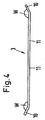
- a transverse strut 3, of which in the embodiment as shown in Fig. 1 is shown using three is in side view in Fig. 4 shown.
- the connected by a connector 11 with a straight course ends 10 of the cross member 3 are bent, as when viewing the Fig. 4 becomes clear, in the direction of the plane defined by the manipulator cloth 1 level.
- This level is in Fig. 4 perpendicular to the plane of the drawing and lies above the cross member 3 shown there.
- the angle W, in which the ends 10 are bent is greater than 90 ° and in this embodiment is approximately 155 °.
- the transverse strut 3 are namely, in this embodiment, near the transition between the connecting piece 11 and the end 10 divided into a first displacement portion 9, which includes the end 10
- Both tubular sections are connected by an inner tube 14 pushed into these sections.
- the inner tube 14 is immovably fixed to the first displacement section 9 by a rivet 15.
- the Inner tube 14 are displaced in the longitudinal direction of the connecting piece 11, thus also the first sliding portion 9 relative to this second displacement portion 13. This displacement is indicated by a double arrow D.
- a slot 16 is provided in the inner tube 14, w moose of a pin 17 (eg a rivet) firmly with the second shift portion 13 of the cross member 3 is connected, is penetrated.
- the interaction between the slot 16 and the pin 17 results in a longitudinal displacement of the inner tube 14 relative to the second displacement section 13, whereas the inner tube 14 is arranged against rotation relative to the second displacement section 13. This is important so that the cross brace 3 with its angularly bent ends 10 maintains the required alignment for the structure of the frame.
- a Federsplint or a Klappsplint can be used instead of the rivet 15 and a split pin, in particular a secured sapwood.
- a Federsplint or a Klappsplint can be used instead of the rivet 15 and a split pin, in particular a secured sapwood.
- a stop 19 is fixed in place via a rivet 18 also. Between this stop 19 and the projecting into the second displacement portion 13 end of the inner tube 14, a coil spring 20 is arranged as a compression spring element. This coil spring presses on the end of the inner tube 14 and forces the inner tube out of the second displacement section 13, thus leading to a bias of the transverse strut 3 designed as a tension strut into a longer extension, in which the first displacement section 9 and the second displacement section 13 are forced away from one another become. A stop for this movement is given by the coil spring 20 facing the end of the elongated hole 16 when it abuts against the pin 17.
- the longitudinal struts 2 are first threaded into the loops 12 and the ends of the longitudinal struts are optionally inserted into the pockets 22, the clamps 4 coming to lie with the slip pin 5 in cutouts 21.
- the cross struts 3 are used. These are first placed with a first end on a Aufsteckzapfen 5 on one of the longitudinal struts 2, then is against the spring force of the coil spring 20 of the strut designed as a cross brace third compressed by the first displacement portion 9 is moved in the direction of the second portion 13. So shortened, if necessary, with slight tightening of the manipulator cloth 1, the end 10 are guided over the slip pin 5. After taking the final position while a spring tension on the frame is maintained, which is caused on the one hand by the elastic manipulator cloth 1, on the other hand by the spring forces of the compression springs 20 in the cross braces. 3
- the angle W which is greater than 90 °, is formed in cooperation with the spring tension of the manipulator cloth 1 and the coil springs 20, a stable and torsion-resistant structure that is very light and can be easily assembled and disassembled.
- the total weight is about 2 kg.
- the entire structure ie the light manipulator in its individual parts, fits into a transport tube of approx. 10 cm in diameter and 110 cm in length. There are no fasteners such as loose screws or the like. Present that can be lost. The entire assembly is done by plugging together.
- the connectors are held by a part of the residual stress of the manipulator cloth 1 and the material of the loops 12 and 22 pockets, partly by the clamping force of the coil springs 20, which is why the connectors are securely held and the manipulator cloth 1 remains reliably tense.
- Fig. 6 shows an alternative of the light manipulator from the Fig. 1 to 5 in that the longitudinal struts 2 instead of the transverse struts 3 are formed with spring-loaded displacement sections 9, 13.
- the cross struts 3 are executed without displacement sections.
- spring-loaded displacement sections 9, 13 may also be provided simultaneously in the longitudinal struts 2 and the transverse struts 3.
- the loops 12 of the manipulator cloth 1 are closed at the corners of the manipulator cloth 1 to pockets 22.
- the remaining loops are not necessarily required in this embodiment with displacement sections 9, 13 only in the longitudinal struts. All four with their ends located in the pockets 22 of the manipulator cloth 1 longitudinal struts 2 are formed with displacement sections. A terminal portion of such a longitudinal strut 2 is in Fig. 6 shown.
- both longitudinal struts Fig. 1 in each case two first displacement sections 9 and two second displacement sections 13.
- Both first and second displacement sections 9, 13 are each connected by an inner tube 14 inserted into these sections.
- the inner tube 14 is fixed immovably to the first displacement portion 9 by a splint 15a.
- the inner tube 14 can be displaced in the longitudinal direction of the longitudinal strut 2, thus also the first displacement section 9 relative to this second displacement section 13.
- This displaceability is indicated by a double arrow D.
- a slot 16 is provided in the inner tube 14, which is penetrated by a pin 17 (for example, a rivet) which is fixedly connected to the second displacement portion 13 of the longitudinal brace 2.
- a stop 19 is fixed in place via a rivet 18 also. Between this stop 19 and the projecting into the second displacement portion 13 end of the inner tube 14, a coil spring 20 is arranged as a compression spring element. This coil spring 20 presses on the end of the inner tube 14 and forces the inner tube 14 out of the second displacement section 13, thus leading to a bias of the clamping strut designed as a longitudinal strut 2 in a longer extension, in which the first displacement portion 9 and the second displacement portion 13 from each other be forced away. A stop for this movement is given by the coil spring 20 facing the end of the elongated hole 16 when it abuts against the pin 17.
- the light manipulator can also be attached to a tripod with the aid of a corresponding adapter.
- displacement sections can also be arranged between two clamps 4 or between two transverse struts. Also, it is conceivable only one first and one to provide a second displacement section per longitudinal strut 2.
Landscapes
- Physics & Mathematics (AREA)
- General Physics & Mathematics (AREA)
- Manipulator (AREA)
- Curtains And Furnishings For Windows Or Doors (AREA)
- Non-Portable Lighting Devices Or Systems Thereof (AREA)
Claims (15)
- Manipulateur de lumière transportable, comprenant une armature et un tissu de manipulateur (1) qui est tendu ou peut être tendu sur l'armature, où l'armature contient au moins une barre de tension (3), qui possède au moins deux sections coulissantes (9, 13), lesquelles peuvent coulisser dans le sens longitudinal de la barre de tension et qui sont connectées ou peuvent être connectées l'une à l'autre, lesquelles sections coulissantes sont soumises à une tension de ressort de manière à ce qu'elles puissent être séparées l'une de l'autre dans le sens longitudinal de la barre de tension en raison de la force du ressort et où le tissu de manipulateur (1) possède des dispositifs de fixation terminaux (12) pour, en particulier, assurer la fixation définitive à l'armature, et où le tissu de manipulateur (1) et/ou les dispositifs de fixation (12) présentent un élément élastique qui en position d'utilisation du manipulateur de lumière tire sur les sections coulissantes (9, 13) pour les rapprocher l'une de l'autre.
- Manipulateur de lumière transportable selon la revendication 1, caractérisé en ce que ladite au moins une barre de tension est tubulaire au moins dans la zone où les deux sections coulissantes (9, 13) sont connectées l'une à l'autre, où un tuyau intérieur (14) ou bien un cylindre intérieur massif sont insérés dans les ouvertures de tuyau adjacentes des sections coulissantes (9, 13), lequel tuyau est connecté fixement à la première des sections coulissantes (9) et connecté de façon mobile avec la seconde des sections coulissantes (13) par le biais d'un guide contraignant (16, 17) agissant dans le sens longitudinal de ladite au moins une barre de tension, sur une course prédéfinie, et que, dans la seconde section coulissante (13), un élément ressort de compression est agencé entre la butée fixe (19) par rapport à ladite section coulissante (13) et l'extrémité du tuyau intérieur (14) ou cylindre intérieur reposant dans l'ouverture de tuyau de ladite section coulissante (13).
- Manipulateur de lumière transportable selon la revendication 2, caractérisé par un ressort hélicoïdal comme élément à ressort de compression (20).
- Manipulateur de lumière transportable selon l'une des revendications 2 ou 3, caractérisé en ce que le guide contraignant (16, 17) est formé d'un trou allongé (16) qui s'étend dans la direction longitudinale de ladite au moins une barre de tension dans le tuyau intérieur (14) ou cylindre intérieur ainsi qu'une goupille (17) fixée à demeure sur la seconde section coulissante et en saillie à travers le tuyau.
- Manipulateur de lumière transportable selon l'une quelconque des revendications précédentes, caractérisé en ce que l'armature possède au moins une barre (2, 3) qui à ses extrémités (10) s'étend en une courbe à un angle (W), en particulier que l'angle (W), avec lequel s'étend la barre dans une courbe à ses extrémités (10), est supérieur à 90°, de préférence dans une fourchette comprise entre 120° et 170°, en particulier est égal à 155°.
- Manipulateur de lumière transportable selon l'une quelconque des revendications précédentes, où l'armature peut être démontée et/ou repliée.
- Manipulateur de lumière transportable selon la revendication 6, où la force produite en position d'utilisation par l'élasticité du tissu de manipulateur sur l'armature assure la cohésion de ladite armature.
- Manipulateur de lumière transportable selon l'une quelconque des revendications précédentes, caractérisé en ce que l'armature est formée de deux barres longitudinales (2) et au moins d'une barre transversale (3) reliant les barres longitudinales (2).
- Manipulateur de lumière transportable selon la revendication 8, où ladite au moins une barre transversale (3) et/ou les barres longitudinales (2) sont conçues comme barres de tension.
- Manipulateur de lumière transportable selon la revendication 9, où ladite au moins une barre transversale (3) est conçue selon la revendication 5.
- Manipulateur de lumière transportable selon l'une quelconque des revendications précédentes, caractérisé par des moyens de connexion, en particulier des goupilles de positionnement (5) ou des douilles d'insertion, sur les barres longitudinales (2) pour connexion avec les extrémités (10), en particulier des extrémités de forme tubulaire et ouvertes, de ladite au moins une barre transversale (3) pour construire l'armature.
- Manipulateur de lumière transportable selon l'une des revendications 5 ou 10, caractérisé en ce que l'axe de direction des goupilles de positionnement (5) ou des douilles d'insertion et des extrémités (10) de la barre transversale (3) en position d'utilisation est le même et défini par l'angle (W) avec lequel la barre transversale (3) tourne à un angle à ses extrémités (10).
- Manipulateur de lumière transportable selon l'une quelconque des revendications précédentes, caractérisé en ce que le tissu de manipulateur (1) possède des poches longitudinales comme dispositifs de fixation (12) pour permettre le serrage avec les barres longitudinales (2), à ses bords longitudinaux prévus pour assurer une connexion avec les barres longitudinales (2).
- Manipulateur de lumière transportable selon la revendication 13, caractérisé en ce que les poches longitudinales sont découpées dans les zones dans lesquelles les barres transversales (3) sont fixées aux barres longitudinales (2).
- Manipulateur de lumière transportable selon l'une quelconque des revendications précédentes, caractérisé en ce que le tissu de manipulateur (1) est un tissu réflecteur ou un tissu diffuseur.
Applications Claiming Priority (2)
| Application Number | Priority Date | Filing Date | Title |
|---|---|---|---|
| DE200920010894 DE202009010894U1 (de) | 2009-08-19 | 2009-08-19 | Transportabler Lichtmanipulator |
| PCT/EP2010/059490 WO2011020642A1 (fr) | 2009-08-19 | 2010-07-02 | Manipulateur de lumière transportable |
Publications (2)
| Publication Number | Publication Date |
|---|---|
| EP2467754A1 EP2467754A1 (fr) | 2012-06-27 |
| EP2467754B1 true EP2467754B1 (fr) | 2016-09-21 |
Family
ID=41429064
Family Applications (1)
| Application Number | Title | Priority Date | Filing Date |
|---|---|---|---|
| EP10730765.4A Not-in-force EP2467754B1 (fr) | 2009-08-19 | 2010-07-02 | Manipulateur de lumière transportable |
Country Status (6)
| Country | Link |
|---|---|
| US (1) | US8875457B2 (fr) |
| EP (1) | EP2467754B1 (fr) |
| CN (1) | CN102483558B (fr) |
| DE (1) | DE202009010894U1 (fr) |
| RU (1) | RU2498377C1 (fr) |
| WO (1) | WO2011020642A1 (fr) |
Families Citing this family (10)
| Publication number | Priority date | Publication date | Assignee | Title |
|---|---|---|---|---|
| MX2010010892A (es) | 2010-10-01 | 2012-04-04 | Eamon Conmac Sebastian O Farrill Haro | Marco neumatico para textiles de control y/o modificacion de luz. |
| CA2949217A1 (fr) * | 2014-06-04 | 2015-12-10 | Officine Maccaferri Italia S.R.L. | Nervure permettant de supporter et de consolider une excavation et procede permettant d'installer une structure destinee a supporter et consolider une excavation |
| CN104809965B (zh) * | 2015-05-07 | 2018-05-29 | 上海易所试实业有限公司 | 一种图片支撑架 |
| CN105240363A (zh) * | 2015-10-29 | 2016-01-13 | 重庆市璧山区红宁汽车配件有限公司 | 盘式刹车片自动液压装置 |
| DE202016101460U1 (de) * | 2016-03-16 | 2016-03-29 | Markus Kreuzer | Vorrichtung zur Beeinflussung des Lichts bei Fotoaufnahmen |
| KR200489435Y1 (ko) * | 2016-02-01 | 2019-09-30 | 카본 시스템 페어발? 게엠베하 | 사진 촬영용 광 영향 장치 |
| US11359762B2 (en) * | 2020-03-03 | 2022-06-14 | Savage Universal Corp | V-pole holder for light modifiers |
| CN113183341A (zh) * | 2021-05-19 | 2021-07-30 | 精良(北京)电子科技有限公司 | 一种用于晶圆解理的绷紧机构、绷膜组件及绷膜方法 |
| CN113178407A (zh) * | 2021-05-19 | 2021-07-27 | 精良(北京)电子科技有限公司 | 一种芯片解理设备 |
| US12385304B2 (en) * | 2021-08-10 | 2025-08-12 | Yuliya SYTNYK | Rotatable suspension rail background system with multiple panels |
Family Cites Families (50)
| Publication number | Priority date | Publication date | Assignee | Title |
|---|---|---|---|---|
| US2129154A (en) * | 1936-03-12 | 1938-09-06 | Charles W Sherman | Diffusing screen |
| US2545251A (en) | 1947-10-07 | 1951-03-13 | Barettella Angelo | Curtain rod |
| US3062157A (en) * | 1960-03-14 | 1962-11-06 | Marquis A Woods | Cargo bracing device |
| US3451153A (en) * | 1967-05-08 | 1969-06-24 | John A Dohanyos | Adjustable framing device |
| US3570412A (en) * | 1968-12-20 | 1971-03-16 | Robert E Holman Jr | Captive brace rod and track |
| US3574447A (en) * | 1969-02-17 | 1971-04-13 | Goodyear Aerospace Corp | Multicurved reflector |
| US3583466A (en) * | 1969-12-17 | 1971-06-08 | Polacoat Inc | Adjustable screen frame for rear projection screen or the like |
| US3836174A (en) * | 1972-10-16 | 1974-09-17 | R Holman | Cargo beam |
| US3952463A (en) * | 1974-05-29 | 1976-04-27 | General Aluminum Products, Inc. | Flexible cover support structure |
| SU559066A1 (ru) * | 1975-10-13 | 1977-05-25 | Головное Предприятие Производственно-Го Объединения "Ватра" | Отражатель |
| US4110003A (en) * | 1975-12-27 | 1978-08-29 | Knox Manufacturing Company | Portable movie screen device |
| US4091485A (en) * | 1976-10-22 | 1978-05-30 | Dohet Pierre E | Collapsible structure |
| US4179193A (en) * | 1978-04-10 | 1979-12-18 | The Boeing Company | Focusing reflector |
| FR2515369A1 (fr) * | 1981-10-23 | 1983-04-29 | Baliozian Mardick | Panneau modulaire en matiere plastique diffuseur ou reflecteur de lumiere pour la photographie, le cinema, la television et l'eclairage de locaux, et dispositif obtenu par l'assemblage de plusieurs de ces panneaux |
| US4532744A (en) * | 1983-09-06 | 1985-08-06 | The Firestone Tire & Rubber Company | Locking device for membrane fastener apparatus |
| US4519151A (en) * | 1983-11-03 | 1985-05-28 | Metalogic, Inc. | Expandable and contractible frame for stretching fabric material, and method |
| US4552438A (en) * | 1984-01-09 | 1985-11-12 | The United States Of America As Represented By The United States Department Of Energy | Cable tensioned membrane solar collector module with variable tension control |
| FR2582227B1 (fr) * | 1985-05-23 | 1988-04-01 | Labarthe Benoit De | Dispositif pour recouvrir ou decouvrir une surface au moyen d'une couverture |
| US4998189A (en) * | 1989-05-04 | 1991-03-05 | Giles Guggemos | Collapsible reflector unit for display structures |
| SU1723410A1 (ru) * | 1989-12-06 | 1992-03-30 | Всесоюзный Научно-Исследовательский Проектно-Конструкторский И Технологический Светотехнический Институт | Отражатель светильника дл теплиц |
| US5104269A (en) * | 1991-02-25 | 1992-04-14 | Jps Corporation | Self-locking adjustable cargo beam |
| GB9203041D0 (en) * | 1992-02-13 | 1992-03-25 | Hodkinson John M | Joints and connectors |
| GB9211186D0 (en) * | 1992-05-27 | 1992-07-08 | Lastolite Ltd | Light-modifying screen for use in photography |
| DE9215330U1 (de) | 1992-11-11 | 1992-12-24 | Geller, Peter, 2000 Hamburg | Transportabler Lichtreflektor |
| CN2163390Y (zh) * | 1992-12-25 | 1994-04-27 | 吴俊� | 便携式反光、测光板 |
| US5557870A (en) * | 1994-07-05 | 1996-09-24 | Bergman; Gerald H. | T-shirt mounting frame |
| US5927668A (en) * | 1995-12-28 | 1999-07-27 | Omni Mount Systems, Inc. | Adjustable framing support system |
| US6102350A (en) * | 1995-12-28 | 2000-08-15 | Omnimount Systems, Inc. | Apparatus for mounting objects, including tension member |
| EP0828044A3 (fr) * | 1996-08-09 | 1998-07-08 | Gale Australia Pty. Ltd. | Structure de protection portable |
| US5944464A (en) * | 1997-06-11 | 1999-08-31 | Utility Trailer Manufacturing Co. | Load restraining ceiling and system for refrigerated vehicles |
| DE69810903D1 (de) * | 1998-05-14 | 2003-02-27 | Elinca S A | Faltbarer Lichtreflektor mit schirmartiger Struktur |
| DE19950950A1 (de) | 1999-10-22 | 2001-11-22 | Aktas Uezeyir | Gardinenklemmstange |
| DE20000923U1 (de) * | 2000-01-20 | 2000-03-30 | Geller, Wolfgang Peter, 21376 Garlstorf | Transportabler Lichtreflektor oder -diffusor |
| FR2810122B1 (fr) * | 2000-06-08 | 2002-11-22 | Patrice Bernard Franco Congard | Ecran escamotable permeable aux ondes sonores |
| WO2002008546A1 (fr) * | 2000-07-22 | 2002-01-31 | Hubertus Greschbach | Module pour la construction de plates-formes |
| CN2433700Y (zh) * | 2000-08-08 | 2001-06-06 | 黄光伟 | 旋转式广告塔 |
| US7160000B2 (en) * | 2003-02-26 | 2007-01-09 | Eldridge Kathleen A | Collapsible frame device and system |
| US8695306B2 (en) * | 2003-06-11 | 2014-04-15 | Sava Cvek | Methods and arrangements for securing fabric |
| US8156994B2 (en) * | 2003-07-09 | 2012-04-17 | Freshair Screen Technology, Llc | Longitudinal frame member and spline |
| US7735540B2 (en) * | 2003-07-09 | 2010-06-15 | Freshair Screen Technology, Llc | Longitudinal frame member and spline |
| DE20316399U1 (de) * | 2003-10-24 | 2004-01-08 | Geller, Wolfgang Peter | Vorrichtung zur Beeinflussung von Licht zur Ausleuchtung eines Sets für Filmaufnahmen, Photoaufnahmen, und/oder Bühne |
| US7054549B2 (en) * | 2003-11-28 | 2006-05-30 | Novoflex Gbr Bothe, Hiesinger Und Mann | Variable background for photographic pictures |
| US7134758B1 (en) * | 2005-06-08 | 2006-11-14 | Baker Michael R | Privacy screen for laptop computer |
| US7337737B1 (en) * | 2005-06-13 | 2008-03-04 | Kazak Composites, Incorporated | Stanchion assembly |
| CN2821616Y (zh) * | 2005-07-08 | 2006-09-27 | 深圳市元科摄影器材有限公司 | 折叠式反光屏 |
| US7609949B2 (en) * | 2006-02-15 | 2009-10-27 | Ealer John S | Portable flag and net kit |
| CN201035293Y (zh) * | 2007-04-02 | 2008-03-12 | 中山立信摄影器材有限公司 | 一种便携式反光屏 |
| DE202009000682U1 (de) * | 2009-01-16 | 2009-03-26 | Geller, Wolfgang Peter | Transportabler faltbarer Lichtgestalter |
| TWM403168U (en) * | 2010-12-06 | 2011-05-01 | Bright Supply Corp | Telescopic holder (5) display screen |
| US8683771B2 (en) * | 2011-04-04 | 2014-04-01 | Quanex Corporation | Adjustable frame assembly and method of assembling the adjustable frame assembly |
-
2009
- 2009-08-19 DE DE200920010894 patent/DE202009010894U1/de not_active Expired - Lifetime
-
2010
- 2010-07-02 WO PCT/EP2010/059490 patent/WO2011020642A1/fr not_active Ceased
- 2010-07-02 CN CN201080037083.1A patent/CN102483558B/zh not_active Expired - Fee Related
- 2010-07-02 EP EP10730765.4A patent/EP2467754B1/fr not_active Not-in-force
- 2010-07-02 US US13/391,050 patent/US8875457B2/en active Active
- 2010-07-02 RU RU2012110235/28A patent/RU2498377C1/ru not_active IP Right Cessation
Also Published As
| Publication number | Publication date |
|---|---|
| DE202009010894U1 (de) | 2009-12-24 |
| US20120170278A1 (en) | 2012-07-05 |
| CN102483558A (zh) | 2012-05-30 |
| EP2467754A1 (fr) | 2012-06-27 |
| CN102483558B (zh) | 2016-11-02 |
| US8875457B2 (en) | 2014-11-04 |
| RU2498377C1 (ru) | 2013-11-10 |
| WO2011020642A1 (fr) | 2011-02-24 |
| RU2012110235A (ru) | 2013-09-27 |
Similar Documents
| Publication | Publication Date | Title |
|---|---|---|
| EP2467754B1 (fr) | Manipulateur de lumière transportable | |
| DE102014103535B4 (de) | Vorrichtung zur Befestigung eines Bauteils an einem Trägerbauteil | |
| DE102012110648B4 (de) | Verriegelungselement, Verbindungsanordnung, Anordnung aus einem ersten Bauteil und einem zweiten Bauteil und Verfahren zur Montage einer solchen Anordnung | |
| DE102013110750B3 (de) | Optische Baugruppe mit einer Fassung mit thermisch abhängigem Kraftausgleich | |
| DE102011113388A1 (de) | Schutzabdeckung | |
| DE102010004277A1 (de) | Trampolin | |
| LU84380A1 (de) | Verbindungsmuffe zum loesbaren befestigen des endes eines ersten stabes an einem zweiten stab | |
| DE102012208482A1 (de) | Befestigungsvorrichtung | |
| EP3108773B1 (fr) | Élement de cadre pour cadre de serrage | |
| DE102013100822A1 (de) | Befestigungssystem und Einbausatz für die Montage eines Montagestegs in einem Schaltschrank | |
| EP4202174B1 (fr) | Kit de construction pour cadre | |
| DE2619830C3 (de) | Abschleppstange für Kraftfahrzeuge | |
| DE3715435C2 (fr) | ||
| DE102018000658A1 (de) | Halterung für ein Telekommunikations-Endgerät und Verfahren zum Einführen eines Telekommunikations-Endgeräts | |
| DE7614128U1 (de) | Rohr- und Kabelschelle | |
| DE2750503B2 (de) | Vorrichtung zum gegenseitigen Verbinden von Profilstäben | |
| EP4515111B1 (fr) | Dispositif de maintien et ensemble de maintien pour systèmes de support publicitaire | |
| DE102007014013B4 (de) | Flugkörperadapterring | |
| DE102013108275B3 (de) | Scharnier | |
| DE102011087620B4 (de) | Scheibenwischvorrichtung | |
| DE102018110172B4 (de) | Haltevorrichtung und Verfahren zum Sichern und/oder Befestigen einer Komponente an einer gehöhlten Außenstruktur eines Raumflugkörpers | |
| WO2017060306A1 (fr) | Dispositif de liaison pour relier rigidement un premier tube à un deuxième tube | |
| DE102024122864A1 (de) | Faltgestell für ein Pagodenzelt | |
| DE202006008989U1 (de) | Gleitelement für eine Schutzabdeckung | |
| DE202024102792U1 (de) | Teleskopierbare Schwenkarmanordnung auf Basis einer Möbeltüraufklappvorrichtung |
Legal Events
| Date | Code | Title | Description |
|---|---|---|---|
| PUAI | Public reference made under article 153(3) epc to a published international application that has entered the european phase |
Free format text: ORIGINAL CODE: 0009012 |
|
| 17P | Request for examination filed |
Effective date: 20120307 |
|
| AK | Designated contracting states |
Kind code of ref document: A1 Designated state(s): AL AT BE BG CH CY CZ DE DK EE ES FI FR GB GR HR HU IE IS IT LI LT LU LV MC MK MT NL NO PL PT RO SE SI SK SM TR |
|
| DAX | Request for extension of the european patent (deleted) | ||
| GRAJ | Information related to disapproval of communication of intention to grant by the applicant or resumption of examination proceedings by the epo deleted |
Free format text: ORIGINAL CODE: EPIDOSDIGR1 |
|
| GRAP | Despatch of communication of intention to grant a patent |
Free format text: ORIGINAL CODE: EPIDOSNIGR1 |
|
| GRAP | Despatch of communication of intention to grant a patent |
Free format text: ORIGINAL CODE: EPIDOSNIGR1 |
|
| RAP1 | Party data changed (applicant data changed or rights of an application transferred) |
Owner name: GELLER, WOLFGANG-PETER |
|
| RIN1 | Information on inventor provided before grant (corrected) |
Inventor name: GELLER, WOLFGANG-PETER |
|
| INTG | Intention to grant announced |
Effective date: 20160518 |
|
| GRAS | Grant fee paid |
Free format text: ORIGINAL CODE: EPIDOSNIGR3 |
|
| GRAA | (expected) grant |
Free format text: ORIGINAL CODE: 0009210 |
|
| AK | Designated contracting states |
Kind code of ref document: B1 Designated state(s): AL AT BE BG CH CY CZ DE DK EE ES FI FR GB GR HR HU IE IS IT LI LT LU LV MC MK MT NL NO PL PT RO SE SI SK SM TR |
|
| REG | Reference to a national code |
Ref country code: GB Ref legal event code: FG4D Free format text: NOT ENGLISH |
|
| REG | Reference to a national code |
Ref country code: CH Ref legal event code: EP |
|
| REG | Reference to a national code |
Ref country code: AT Ref legal event code: REF Ref document number: 831519 Country of ref document: AT Kind code of ref document: T Effective date: 20161015 |
|
| REG | Reference to a national code |
Ref country code: IE Ref legal event code: FG4D Free format text: LANGUAGE OF EP DOCUMENT: GERMAN |
|
| REG | Reference to a national code |
Ref country code: DE Ref legal event code: R096 Ref document number: 502010012446 Country of ref document: DE |
|
| REG | Reference to a national code |
Ref country code: LT Ref legal event code: MG4D Ref country code: NL Ref legal event code: MP Effective date: 20160921 |
|
| PG25 | Lapsed in a contracting state [announced via postgrant information from national office to epo] |
Ref country code: LT Free format text: LAPSE BECAUSE OF FAILURE TO SUBMIT A TRANSLATION OF THE DESCRIPTION OR TO PAY THE FEE WITHIN THE PRESCRIBED TIME-LIMIT Effective date: 20160921 Ref country code: FI Free format text: LAPSE BECAUSE OF FAILURE TO SUBMIT A TRANSLATION OF THE DESCRIPTION OR TO PAY THE FEE WITHIN THE PRESCRIBED TIME-LIMIT Effective date: 20160921 Ref country code: NO Free format text: LAPSE BECAUSE OF FAILURE TO SUBMIT A TRANSLATION OF THE DESCRIPTION OR TO PAY THE FEE WITHIN THE PRESCRIBED TIME-LIMIT Effective date: 20161221 |
|
| PG25 | Lapsed in a contracting state [announced via postgrant information from national office to epo] |
Ref country code: SE Free format text: LAPSE BECAUSE OF FAILURE TO SUBMIT A TRANSLATION OF THE DESCRIPTION OR TO PAY THE FEE WITHIN THE PRESCRIBED TIME-LIMIT Effective date: 20160921 Ref country code: LV Free format text: LAPSE BECAUSE OF FAILURE TO SUBMIT A TRANSLATION OF THE DESCRIPTION OR TO PAY THE FEE WITHIN THE PRESCRIBED TIME-LIMIT Effective date: 20160921 Ref country code: GR Free format text: LAPSE BECAUSE OF FAILURE TO SUBMIT A TRANSLATION OF THE DESCRIPTION OR TO PAY THE FEE WITHIN THE PRESCRIBED TIME-LIMIT Effective date: 20161222 Ref country code: NL Free format text: LAPSE BECAUSE OF FAILURE TO SUBMIT A TRANSLATION OF THE DESCRIPTION OR TO PAY THE FEE WITHIN THE PRESCRIBED TIME-LIMIT Effective date: 20160921 |
|
| PG25 | Lapsed in a contracting state [announced via postgrant information from national office to epo] |
Ref country code: RO Free format text: LAPSE BECAUSE OF FAILURE TO SUBMIT A TRANSLATION OF THE DESCRIPTION OR TO PAY THE FEE WITHIN THE PRESCRIBED TIME-LIMIT Effective date: 20160921 Ref country code: EE Free format text: LAPSE BECAUSE OF FAILURE TO SUBMIT A TRANSLATION OF THE DESCRIPTION OR TO PAY THE FEE WITHIN THE PRESCRIBED TIME-LIMIT Effective date: 20160921 |
|
| PG25 | Lapsed in a contracting state [announced via postgrant information from national office to epo] |
Ref country code: CZ Free format text: LAPSE BECAUSE OF FAILURE TO SUBMIT A TRANSLATION OF THE DESCRIPTION OR TO PAY THE FEE WITHIN THE PRESCRIBED TIME-LIMIT Effective date: 20160921 Ref country code: IS Free format text: LAPSE BECAUSE OF FAILURE TO SUBMIT A TRANSLATION OF THE DESCRIPTION OR TO PAY THE FEE WITHIN THE PRESCRIBED TIME-LIMIT Effective date: 20170121 Ref country code: ES Free format text: LAPSE BECAUSE OF FAILURE TO SUBMIT A TRANSLATION OF THE DESCRIPTION OR TO PAY THE FEE WITHIN THE PRESCRIBED TIME-LIMIT Effective date: 20160921 Ref country code: PT Free format text: LAPSE BECAUSE OF FAILURE TO SUBMIT A TRANSLATION OF THE DESCRIPTION OR TO PAY THE FEE WITHIN THE PRESCRIBED TIME-LIMIT Effective date: 20170123 Ref country code: SK Free format text: LAPSE BECAUSE OF FAILURE TO SUBMIT A TRANSLATION OF THE DESCRIPTION OR TO PAY THE FEE WITHIN THE PRESCRIBED TIME-LIMIT Effective date: 20160921 Ref country code: BG Free format text: LAPSE BECAUSE OF FAILURE TO SUBMIT A TRANSLATION OF THE DESCRIPTION OR TO PAY THE FEE WITHIN THE PRESCRIBED TIME-LIMIT Effective date: 20161221 Ref country code: PL Free format text: LAPSE BECAUSE OF FAILURE TO SUBMIT A TRANSLATION OF THE DESCRIPTION OR TO PAY THE FEE WITHIN THE PRESCRIBED TIME-LIMIT Effective date: 20160921 Ref country code: SM Free format text: LAPSE BECAUSE OF FAILURE TO SUBMIT A TRANSLATION OF THE DESCRIPTION OR TO PAY THE FEE WITHIN THE PRESCRIBED TIME-LIMIT Effective date: 20160921 |
|
| REG | Reference to a national code |
Ref country code: DE Ref legal event code: R097 Ref document number: 502010012446 Country of ref document: DE |
|
| PG25 | Lapsed in a contracting state [announced via postgrant information from national office to epo] |
Ref country code: IT Free format text: LAPSE BECAUSE OF FAILURE TO SUBMIT A TRANSLATION OF THE DESCRIPTION OR TO PAY THE FEE WITHIN THE PRESCRIBED TIME-LIMIT Effective date: 20160921 |
|
| REG | Reference to a national code |
Ref country code: FR Ref legal event code: PLFP Year of fee payment: 8 |
|
| PLBE | No opposition filed within time limit |
Free format text: ORIGINAL CODE: 0009261 |
|
| STAA | Information on the status of an ep patent application or granted ep patent |
Free format text: STATUS: NO OPPOSITION FILED WITHIN TIME LIMIT |
|
| PG25 | Lapsed in a contracting state [announced via postgrant information from national office to epo] |
Ref country code: DK Free format text: LAPSE BECAUSE OF FAILURE TO SUBMIT A TRANSLATION OF THE DESCRIPTION OR TO PAY THE FEE WITHIN THE PRESCRIBED TIME-LIMIT Effective date: 20160921 |
|
| 26N | No opposition filed |
Effective date: 20170622 |
|
| PG25 | Lapsed in a contracting state [announced via postgrant information from national office to epo] |
Ref country code: SI Free format text: LAPSE BECAUSE OF FAILURE TO SUBMIT A TRANSLATION OF THE DESCRIPTION OR TO PAY THE FEE WITHIN THE PRESCRIBED TIME-LIMIT Effective date: 20160921 |
|
| REG | Reference to a national code |
Ref country code: CH Ref legal event code: PL |
|
| REG | Reference to a national code |
Ref country code: IE Ref legal event code: MM4A |
|
| PG25 | Lapsed in a contracting state [announced via postgrant information from national office to epo] |
Ref country code: CH Free format text: LAPSE BECAUSE OF NON-PAYMENT OF DUE FEES Effective date: 20170731 Ref country code: LI Free format text: LAPSE BECAUSE OF NON-PAYMENT OF DUE FEES Effective date: 20170731 Ref country code: IE Free format text: LAPSE BECAUSE OF NON-PAYMENT OF DUE FEES Effective date: 20170702 |
|
| REG | Reference to a national code |
Ref country code: BE Ref legal event code: MM Effective date: 20170731 |
|
| PG25 | Lapsed in a contracting state [announced via postgrant information from national office to epo] |
Ref country code: LU Free format text: LAPSE BECAUSE OF NON-PAYMENT OF DUE FEES Effective date: 20170702 |
|
| REG | Reference to a national code |
Ref country code: FR Ref legal event code: PLFP Year of fee payment: 9 |
|
| PG25 | Lapsed in a contracting state [announced via postgrant information from national office to epo] |
Ref country code: BE Free format text: LAPSE BECAUSE OF NON-PAYMENT OF DUE FEES Effective date: 20170731 |
|
| REG | Reference to a national code |
Ref country code: AT Ref legal event code: MM01 Ref document number: 831519 Country of ref document: AT Kind code of ref document: T Effective date: 20170702 |
|
| PG25 | Lapsed in a contracting state [announced via postgrant information from national office to epo] |
Ref country code: MT Free format text: LAPSE BECAUSE OF FAILURE TO SUBMIT A TRANSLATION OF THE DESCRIPTION OR TO PAY THE FEE WITHIN THE PRESCRIBED TIME-LIMIT Effective date: 20160921 |
|
| PG25 | Lapsed in a contracting state [announced via postgrant information from national office to epo] |
Ref country code: AL Free format text: LAPSE BECAUSE OF FAILURE TO SUBMIT A TRANSLATION OF THE DESCRIPTION OR TO PAY THE FEE WITHIN THE PRESCRIBED TIME-LIMIT Effective date: 20160921 |
|
| PGFP | Annual fee paid to national office [announced via postgrant information from national office to epo] |
Ref country code: GB Payment date: 20180912 Year of fee payment: 17 |
|
| PG25 | Lapsed in a contracting state [announced via postgrant information from national office to epo] |
Ref country code: AT Free format text: LAPSE BECAUSE OF NON-PAYMENT OF DUE FEES Effective date: 20170702 |
|
| PG25 | Lapsed in a contracting state [announced via postgrant information from national office to epo] |
Ref country code: MC Free format text: LAPSE BECAUSE OF FAILURE TO SUBMIT A TRANSLATION OF THE DESCRIPTION OR TO PAY THE FEE WITHIN THE PRESCRIBED TIME-LIMIT Effective date: 20160921 Ref country code: HU Free format text: LAPSE BECAUSE OF FAILURE TO SUBMIT A TRANSLATION OF THE DESCRIPTION OR TO PAY THE FEE WITHIN THE PRESCRIBED TIME-LIMIT; INVALID AB INITIO Effective date: 20100702 |
|
| PG25 | Lapsed in a contracting state [announced via postgrant information from national office to epo] |
Ref country code: CY Free format text: LAPSE BECAUSE OF NON-PAYMENT OF DUE FEES Effective date: 20160921 |
|
| PGFP | Annual fee paid to national office [announced via postgrant information from national office to epo] |
Ref country code: DE Payment date: 20190626 Year of fee payment: 10 |
|
| PG25 | Lapsed in a contracting state [announced via postgrant information from national office to epo] |
Ref country code: MK Free format text: LAPSE BECAUSE OF FAILURE TO SUBMIT A TRANSLATION OF THE DESCRIPTION OR TO PAY THE FEE WITHIN THE PRESCRIBED TIME-LIMIT Effective date: 20160921 |
|
| GBPC | Gb: european patent ceased through non-payment of renewal fee |
Effective date: 20190702 |
|
| PG25 | Lapsed in a contracting state [announced via postgrant information from national office to epo] |
Ref country code: TR Free format text: LAPSE BECAUSE OF FAILURE TO SUBMIT A TRANSLATION OF THE DESCRIPTION OR TO PAY THE FEE WITHIN THE PRESCRIBED TIME-LIMIT Effective date: 20160921 |
|
| PG25 | Lapsed in a contracting state [announced via postgrant information from national office to epo] |
Ref country code: GB Free format text: LAPSE BECAUSE OF NON-PAYMENT OF DUE FEES Effective date: 20190702 |
|
| PG25 | Lapsed in a contracting state [announced via postgrant information from national office to epo] |
Ref country code: HR Free format text: LAPSE BECAUSE OF FAILURE TO SUBMIT A TRANSLATION OF THE DESCRIPTION OR TO PAY THE FEE WITHIN THE PRESCRIBED TIME-LIMIT Effective date: 20160921 Ref country code: FR Free format text: LAPSE BECAUSE OF NON-PAYMENT OF DUE FEES Effective date: 20190731 |
|
| REG | Reference to a national code |
Ref country code: DE Ref legal event code: R119 Ref document number: 502010012446 Country of ref document: DE |
|
| PG25 | Lapsed in a contracting state [announced via postgrant information from national office to epo] |
Ref country code: DE Free format text: LAPSE BECAUSE OF NON-PAYMENT OF DUE FEES Effective date: 20210202 |