EP2467754B1 - Transportable lightmanipulator - Google Patents
Transportable lightmanipulator Download PDFInfo
- Publication number
- EP2467754B1 EP2467754B1 EP10730765.4A EP10730765A EP2467754B1 EP 2467754 B1 EP2467754 B1 EP 2467754B1 EP 10730765 A EP10730765 A EP 10730765A EP 2467754 B1 EP2467754 B1 EP 2467754B1
- Authority
- EP
- European Patent Office
- Prior art keywords
- portable light
- cloth
- frame
- longitudinal
- manipulator
- Prior art date
- Legal status (The legal status is an assumption and is not a legal conclusion. Google has not performed a legal analysis and makes no representation as to the accuracy of the status listed.)
- Not-in-force
Links
- 239000004744 fabric Substances 0.000 claims description 66
- 230000006835 compression Effects 0.000 claims description 7
- 238000007906 compression Methods 0.000 claims description 7
- 230000000284 resting effect Effects 0.000 claims 1
- 238000006073 displacement reaction Methods 0.000 description 62
- 238000010276 construction Methods 0.000 description 6
- 239000000463 material Substances 0.000 description 4
- 230000008901 benefit Effects 0.000 description 3
- 230000003993 interaction Effects 0.000 description 3
- 230000032683 aging Effects 0.000 description 2
- 238000011161 development Methods 0.000 description 2
- 230000018109 developmental process Effects 0.000 description 2
- 230000000694 effects Effects 0.000 description 2
- 239000013013 elastic material Substances 0.000 description 2
- 230000006872 improvement Effects 0.000 description 2
- 230000035882 stress Effects 0.000 description 2
- 241000282994 Cervidae Species 0.000 description 1
- 230000009471 action Effects 0.000 description 1
- 230000006978 adaptation Effects 0.000 description 1
- 230000003679 aging effect Effects 0.000 description 1
- 230000005540 biological transmission Effects 0.000 description 1
- 239000011248 coating agent Substances 0.000 description 1
- 238000000576 coating method Methods 0.000 description 1
- 230000001419 dependent effect Effects 0.000 description 1
- 238000005286 illumination Methods 0.000 description 1
- 238000004519 manufacturing process Methods 0.000 description 1
- 238000005259 measurement Methods 0.000 description 1
- 239000012858 resilient material Substances 0.000 description 1
- 239000007787 solid Substances 0.000 description 1
- 239000004753 textile Substances 0.000 description 1
- 230000007704 transition Effects 0.000 description 1
Images


Classifications
-
- G—PHYSICS
- G03—PHOTOGRAPHY; CINEMATOGRAPHY; ANALOGOUS TECHNIQUES USING WAVES OTHER THAN OPTICAL WAVES; ELECTROGRAPHY; HOLOGRAPHY
- G03B—APPARATUS OR ARRANGEMENTS FOR TAKING PHOTOGRAPHS OR FOR PROJECTING OR VIEWING THEM; APPARATUS OR ARRANGEMENTS EMPLOYING ANALOGOUS TECHNIQUES USING WAVES OTHER THAN OPTICAL WAVES; ACCESSORIES THEREFOR
- G03B15/00—Special procedures for taking photographs; Apparatus therefor
- G03B15/02—Illuminating scene
- G03B15/06—Special arrangements of screening, diffusing, or reflecting devices, e.g. in studio
-
- F—MECHANICAL ENGINEERING; LIGHTING; HEATING; WEAPONS; BLASTING
- F21—LIGHTING
- F21V—FUNCTIONAL FEATURES OR DETAILS OF LIGHTING DEVICES OR SYSTEMS THEREOF; STRUCTURAL COMBINATIONS OF LIGHTING DEVICES WITH OTHER ARTICLES, NOT OTHERWISE PROVIDED FOR
- F21V7/00—Reflectors for light sources
- F21V7/10—Construction
- F21V7/18—Construction with provision for folding or collapsing
Definitions
- the invention relates to a portable light manipulator.
- Such a portable light manipulator is in the form of a light reflector, for example in the EP 0 597 199 A1 described.
- This light reflector described there is widely used in practice and is there used to illuminate sets for film and photo shoots. He has the particular advantage that it can be quickly and easily disassembled into a few parts and then forms a light and easy to be transported by a person unit. Likewise, it is relatively quick to set up at the site, so that even here a quick deployment is guaranteed and not lost valuable recording times.
- similarly constructed light manipulators are known in which instead of the reflector cloth, e.g. a light diffuser cloth is used to diffuse the receiving set to diffuse the incident light to achieve softer contours.
- the sole application of the holding force on the frame by the fabric tension not only requires a particularly precise measurement of the cloth and adaptation of the dimensions to apply the right amount of clamping force, also can with an aging of the cloth, the clamping force decrease, so that then a sufficient Halt the frame can not even be guaranteed.
- the inventor has taken on the task to remedy the situation and to provide an improved portable light manipulator, which is easier to use both in construction and a higher tolerance in terms of fabric tension or tension due to the elasticity of the device for fixing to the longitudinal struts allowed and counteracts a decrease in these stresses due to aging effects or even in the case of such aging still reaches a sufficient and reliable hold of the light manipulator in the position of use.
- the tensioning strut is formed from at least two displacement sections which are displaceable relative to each other in the longitudinal direction and which are displaceable or connectable to one another in the longitudinal direction.
- a spring force is provided between the displacement sections, which forces these sections away from each other, so the tension strut spreads.
- the clamping strut with abutting shift sections in the region of these displacement sections can be formed tubular and in the tube openings of the displacement sections can be used with one end of an inner tube or a solid inner cylinder be, on the one hand ensures the connection, on the other hand accomplished the Relativverschiebles in the longitudinal direction.
- This inserted inner tube or the inner cylinder is arranged at a first of the displacement sections fixed to this, displaceably guided to a second of the displacement sections forcibly guided in the longitudinal direction of the tensioning strut.
- This positive guide extends over a given stroke, which is ultimately determined by the geometry of the frame and the desired additional clamping effect.
- This compression spring element may for example be a helical spring.
- the forced operation should in particular when, as provided according to claim 5 and following the ends of the strut run angled, be rotationally fixed and allow only a longitudinal displacement, however, prevent a relative rotation. This can e.g. carried out by a constructive solution as specified in claim 4.
- the slot which is penetrated by the pin, for an exclusive Relativbeweg sadness in the axial direction, a rotational movement about the longitudinal axis is prevented by the hold between the slot and pin.
- the frame is formed not only in one plane, but undergoes an alignment in a third dimension.
- the frame is still stable in the assembled state and in particular torsionally rigid. This is not only true for outdoor use, where on the portable light manipulator e.g. can also act torsional forces by wind influence, advantage. Even with indoor shots such increased stability leads to a significant improvement in handling.
- an undesired bulging of the manipulator cloth in the region of struts extending behind the manipulator cloth can be avoided by the angling.
- the frame according to claim 6 is designed as a collapsible and / or collapsible frame. This makes it particularly space-saving and easy to transport.
- the frame is in a particularly simple Design formed by two longitudinal struts and at least one cross strut.
- the longitudinal struts can be brought into coincidence with the longitudinal sides of the manipulator cloth and connected with them.
- the at least one crossbar then extends between the longitudinal struts. It is advantageously attached in the middle of the two parallel longitudinal struts.
- At least one transverse strut is executed angled according to claim 5.
- a simple way to build the transportable light manipulator according to claim 8, is to provide connecting means, in particular Aufsteckzapfen on the longitudinal struts for connection to, in particular tubular open, ends of at least one transverse strut.
- This type of connection is easy to manufacture and stable in the assembled state.
- receiving sleeves or plug-in sockets can equally well be provided on the longitudinal struts into which the cross struts can be inserted with their ends. Even with such a solution, which is ultimately nothing more than a constructive reversal of the pin solution, a simple construction and a stable hold in the assembled state is achieved in a simple manner.
- the Aufsteckzapfen or corresponding Einsteckhülsen are aligned so that they are given by the angle to which the crossbar is angled at its ends, angled run.
- a simple embodiment of the means for fixing the manipulator cloth on the longitudinal struts is for this purpose to the Long edges of the manipulator cloth to provide longitudinal pockets.
- These longitudinal pockets can be formed, for example, by loops, which are either formed in the manipulator cloth itself or firmly connected to it, eg sewn.
- These loops themselves can also consist of a textile material, in particular one with elasticity.
- the elasticity of the loops may promote the support of the frame.
- the manipulator cloth itself is elastic, correspondingly arranged loops can be made of non-elastic material or even of an elastic material, whereby in the latter case the elasticity of the clothing (formed from manipulator cloth and loops) is increased once more.
- the construction of the transportable light manipulator is simplified if cutouts are provided in the longitudinal pockets in the areas in which cross struts are fixed to the longitudinal struts. These cutouts can extend both on the back, as well as on a front side of the transportable Lichtmanipulators to ensure free access to the junction between the longitudinal struts and cross braces and thus to allow unhindered assembly of the light manipulator.
- the light manipulator when the light manipulator has large dimensions, e.g. a width of more than 1.5 m, it is for a compact form of the transportable light reflector in the disassembled state advantageous if the longitudinal struts and / or cross member are divisible in the longitudinal direction. For then these elements can be shortened again by splitting when folding (in the disassembled state of the light manipulator).
- the transportable, rigid longitudinal struts or cross strut are limited in length, so that they can be easily carried by a person.
- the portable light manipulator according to the invention can be designed as a light reflector, for which purpose the manipulator cloth is a reflector cloth with e.g. a reflective coating, it may as well be a light diffuser with a diffuser cloth as a manipulator cloth with light attenuation values in a desired range.
- the manipulator cloth is a reflector cloth with e.g. a reflective coating
- it may as well be a light diffuser with a diffuser cloth as a manipulator cloth with light attenuation values in a desired range.
- the in Fig. 1 illustrated light manipulator is formed by a frame, which is essentially formed of two longitudinal struts 2 and three designed as clamping struts cross struts 3, as well as a stretched over this frame manipulator cloth 1.
- the manipulator cloth 1 may in particular be a reflector cloth or a diffuser cloth.
- the manipulator cloth 1 consists of a resilient material in which, for example, elastic threads are incorporated in the cloth.
- the spring tension is effective to at least hold together the frame and thus to prevent that the connections between the longitudinal struts 2 and cross struts 3 solve.
- loops 12 are formed on the manipulator cloth through which the longitudinal struts 2 are guided. These loops 12 can either be formed from the material of the manipulator cloth itself or be firmly connected, for example sewn, from a separate material and with the actual manipulator cloth.
- the loops 12 are closed to pockets 22. In these pockets, the ends of the longitudinal struts 2 are added. Such pockets are particularly advantageous if the longitudinal struts 2 spring-loaded displacement sections 9, 13 have (see Fig. 6 )
- Fig. 2 it can be seen that 2 brackets 4 are attached to the longitudinal struts with 4 Aufsteckzapfen 5 by rivets 6.
- the Aufsteckzapfen 5 fit tightly into the tubes that form the crossbar 3.
- caps 7 are attached to the ends of the longitudinal struts. Instead of the caps 7 can also plug in the pipe ends be used.
- the longitudinal struts 2 are divided in this embodiment, in order to obtain corresponding shorter parts in transport position. In the division they are connected by Aufsteckmuffen 8 (see Fig. 3 ).
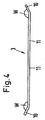
- a transverse strut 3, of which in the embodiment as shown in Fig. 1 is shown using three is in side view in Fig. 4 shown.
- the connected by a connector 11 with a straight course ends 10 of the cross member 3 are bent, as when viewing the Fig. 4 becomes clear, in the direction of the plane defined by the manipulator cloth 1 level.
- This level is in Fig. 4 perpendicular to the plane of the drawing and lies above the cross member 3 shown there.
- the angle W, in which the ends 10 are bent is greater than 90 ° and in this embodiment is approximately 155 °.
- the transverse strut 3 are namely, in this embodiment, near the transition between the connecting piece 11 and the end 10 divided into a first displacement portion 9, which includes the end 10
- Both tubular sections are connected by an inner tube 14 pushed into these sections.
- the inner tube 14 is immovably fixed to the first displacement section 9 by a rivet 15.
- the Inner tube 14 are displaced in the longitudinal direction of the connecting piece 11, thus also the first sliding portion 9 relative to this second displacement portion 13. This displacement is indicated by a double arrow D.
- a slot 16 is provided in the inner tube 14, w moose of a pin 17 (eg a rivet) firmly with the second shift portion 13 of the cross member 3 is connected, is penetrated.
- the interaction between the slot 16 and the pin 17 results in a longitudinal displacement of the inner tube 14 relative to the second displacement section 13, whereas the inner tube 14 is arranged against rotation relative to the second displacement section 13. This is important so that the cross brace 3 with its angularly bent ends 10 maintains the required alignment for the structure of the frame.
- a Federsplint or a Klappsplint can be used instead of the rivet 15 and a split pin, in particular a secured sapwood.
- a Federsplint or a Klappsplint can be used instead of the rivet 15 and a split pin, in particular a secured sapwood.
- a stop 19 is fixed in place via a rivet 18 also. Between this stop 19 and the projecting into the second displacement portion 13 end of the inner tube 14, a coil spring 20 is arranged as a compression spring element. This coil spring presses on the end of the inner tube 14 and forces the inner tube out of the second displacement section 13, thus leading to a bias of the transverse strut 3 designed as a tension strut into a longer extension, in which the first displacement section 9 and the second displacement section 13 are forced away from one another become. A stop for this movement is given by the coil spring 20 facing the end of the elongated hole 16 when it abuts against the pin 17.
- the longitudinal struts 2 are first threaded into the loops 12 and the ends of the longitudinal struts are optionally inserted into the pockets 22, the clamps 4 coming to lie with the slip pin 5 in cutouts 21.
- the cross struts 3 are used. These are first placed with a first end on a Aufsteckzapfen 5 on one of the longitudinal struts 2, then is against the spring force of the coil spring 20 of the strut designed as a cross brace third compressed by the first displacement portion 9 is moved in the direction of the second portion 13. So shortened, if necessary, with slight tightening of the manipulator cloth 1, the end 10 are guided over the slip pin 5. After taking the final position while a spring tension on the frame is maintained, which is caused on the one hand by the elastic manipulator cloth 1, on the other hand by the spring forces of the compression springs 20 in the cross braces. 3
- the angle W which is greater than 90 °, is formed in cooperation with the spring tension of the manipulator cloth 1 and the coil springs 20, a stable and torsion-resistant structure that is very light and can be easily assembled and disassembled.
- the total weight is about 2 kg.
- the entire structure ie the light manipulator in its individual parts, fits into a transport tube of approx. 10 cm in diameter and 110 cm in length. There are no fasteners such as loose screws or the like. Present that can be lost. The entire assembly is done by plugging together.
- the connectors are held by a part of the residual stress of the manipulator cloth 1 and the material of the loops 12 and 22 pockets, partly by the clamping force of the coil springs 20, which is why the connectors are securely held and the manipulator cloth 1 remains reliably tense.
- Fig. 6 shows an alternative of the light manipulator from the Fig. 1 to 5 in that the longitudinal struts 2 instead of the transverse struts 3 are formed with spring-loaded displacement sections 9, 13.
- the cross struts 3 are executed without displacement sections.
- spring-loaded displacement sections 9, 13 may also be provided simultaneously in the longitudinal struts 2 and the transverse struts 3.
- the loops 12 of the manipulator cloth 1 are closed at the corners of the manipulator cloth 1 to pockets 22.
- the remaining loops are not necessarily required in this embodiment with displacement sections 9, 13 only in the longitudinal struts. All four with their ends located in the pockets 22 of the manipulator cloth 1 longitudinal struts 2 are formed with displacement sections. A terminal portion of such a longitudinal strut 2 is in Fig. 6 shown.
- both longitudinal struts Fig. 1 in each case two first displacement sections 9 and two second displacement sections 13.
- Both first and second displacement sections 9, 13 are each connected by an inner tube 14 inserted into these sections.
- the inner tube 14 is fixed immovably to the first displacement portion 9 by a splint 15a.
- the inner tube 14 can be displaced in the longitudinal direction of the longitudinal strut 2, thus also the first displacement section 9 relative to this second displacement section 13.
- This displaceability is indicated by a double arrow D.
- a slot 16 is provided in the inner tube 14, which is penetrated by a pin 17 (for example, a rivet) which is fixedly connected to the second displacement portion 13 of the longitudinal brace 2.
- a stop 19 is fixed in place via a rivet 18 also. Between this stop 19 and the projecting into the second displacement portion 13 end of the inner tube 14, a coil spring 20 is arranged as a compression spring element. This coil spring 20 presses on the end of the inner tube 14 and forces the inner tube 14 out of the second displacement section 13, thus leading to a bias of the clamping strut designed as a longitudinal strut 2 in a longer extension, in which the first displacement portion 9 and the second displacement portion 13 from each other be forced away. A stop for this movement is given by the coil spring 20 facing the end of the elongated hole 16 when it abuts against the pin 17.
- the light manipulator can also be attached to a tripod with the aid of a corresponding adapter.
- displacement sections can also be arranged between two clamps 4 or between two transverse struts. Also, it is conceivable only one first and one to provide a second displacement section per longitudinal strut 2.
Landscapes
- Physics & Mathematics (AREA)
- General Physics & Mathematics (AREA)
- Manipulator (AREA)
- Curtains And Furnishings For Windows Or Doors (AREA)
- Non-Portable Lighting Devices Or Systems Thereof (AREA)
Description
Die Erfindung betrifft einen transportablen Lichtmanipulator.The invention relates to a portable light manipulator.
Ein solcher transportabler Lichtmanipulator ist in Form eines Lichtreflektors z.B. in der
In der Praxis sind neben der Verwendung als Lichtreflektor gleichartig aufgebaute Lichtmanipulatoren bekannt, bei denen anstelle des Reflektortuches z.B. ein Lichtdiffusortuch eingesetzt wird, um zur Ausleuchtung des Aufnahmesets ein Diffundieren des einfallenden Lichtes zu bewerkstelligen und damit weichere Konturen zu erzielen.In practice, in addition to the use as a light reflector, similarly constructed light manipulators are known in which instead of the reflector cloth, e.g. a light diffuser cloth is used to diffuse the receiving set to diffuse the incident light to achieve softer contours.
Auch wenn sich die bekannten transportablen Lichtmanipulatoren dem Grunde nach gut bewährt haben, gibt es hier doch noch Verbesserungsbedarf. So ist zum einen beim Aufbau des vorbekannten transportablen Lichtmanipulators der Kraftaufwand zum Befestigen der Querstrebe an den Längsstreben nicht unerheblich, da dabei jedes Mal nahezu die vollständige Spannung zu überwinden ist, die aufgrund des elastischen Manipulatortuches bzw. der elastischen Einrichtungen zum Festlegen an den Längsstreben aufgebracht wird. Je nach Elastizität und insbesondere Alter des Manipulatortuches bzw. der Einrichtung zum Festlegen der Längsstreben kann dieser Kraftaufwand erheblich sein, so dass insbesondere schwächere Personen oder weibliche Assistenten Schwierigkeiten beim Aufbau des transportablen Lichtmanipulators haben und Hilfe bedürfen. Darüber hinaus erfordert die alleinige Aufbringung der Haltekraft auf das Rahmengestell durch die Tuchspannung nicht nur ein besonders präzises Abmessen des Tuches und Anpassung der Dimensionen zur Aufbringung des richtigen Maßes an Spannkraft, auch kann bei einem Altern des Tuches die Spannkraft nachlassen, so dass dann ein ausreichender Halt des Rahmengestells sogar nicht mehr sichergestellt sein kann.Although the well-known portable light manipulators have basically proven themselves, there is still room for improvement here. Thus, on the one hand in the construction of the known portable light manipulator of the force to fasten the cross member to the longitudinal struts not insignificant, since each time almost complete tension is overcome, which applied due to the elastic manipulator cloth or the elastic means for fixing to the longitudinal struts becomes. Depending on the elasticity and in particular the age of the manipulator cloth or the device for fixing the longitudinal struts, this expenditure of force can be considerable, so that in particular weaker persons or female assistants have difficulties in constructing the transportable light manipulator and need help. In addition, the sole application of the holding force on the frame by the fabric tension not only requires a particularly precise measurement of the cloth and adaptation of the dimensions to apply the right amount of clamping force, also can with an aging of the cloth, the clamping force decrease, so that then a sufficient Halt the frame can not even be guaranteed.
Hier hat es sich der Erfinder zur Aufgabe gemacht, Abhilfe zu schaffen und einen verbesserten transportablen Lichtmanipulator anzugeben, der sowohl im Aufbau einfacher zu bedienen ist als auch eine höhere Toleranz hinsichtlich der Tuchspannung bzw. der Spannung aufgrund der Elastizität der Einrichtung zum Festlegen an den Längsstreben erlaubt und einem Nachlassen dieser Spannungen durch Alterungseffekte entgegenwirkt bzw. auch im Falle eines solchen Alterns noch immer einen ausreichenden und zuverlässigen Halt des Lichtmanipulators in Gebrauchsstellung erreicht.Here, the inventor has taken on the task to remedy the situation and to provide an improved portable light manipulator, which is easier to use both in construction and a higher tolerance in terms of fabric tension or tension due to the elasticity of the device for fixing to the longitudinal struts allowed and counteracts a decrease in these stresses due to aging effects or even in the case of such aging still reaches a sufficient and reliable hold of the light manipulator in the position of use.
Diese Aufgabe wird erfindungsgemäß gelöst durch einen transportablen Lichtmanipulator mit den Merkmalen des Schutzanspruchs 1. Vorteilhafte Weiterbildungen eines solchen erfindungsgemäßen transportablen Lichtmanipulators sind in den abhängigen Ansprüchen 2 bis 15 genannt.This object is achieved by a portable light manipulator with the features of the
Der wesentliche Gedanke und die Basis der Erfindung besteht darin, dass wenigstens eine Strebe anstelle wie im Stand der Technik ein allein passives Strebenelement zu sein, nunmehr aktiv zum Aufbau der Spannung im Manipulatortuch bzw. in dem aufgebauten Lichtmanipulator selbst beiträgt, also als Spannstrebe ausgeführt ist. Hierzu ist die Spannstrebe aus wenigstens zwei in deren Längsrichtung gegeneinander verschiebbaren Verschiebeabschnitten gebildet, die - in Längsrichtung verschiebbar - miteinander verbunden oder verbindbar sind. Dabei ist zwischen den Verschiebeabschnitten eine Federkraft vorgesehen, die diese Abschnitte voneinander weg zwingt, die Spannstrebe also spreizt.The essential idea and the basis of the invention is that at least one strut, instead of being a solely passive strut element as in the prior art, now actively contributes to the buildup of tension in the manipulator cloth or in the built-up light manipulator itself, ie is designed as a tension strut , For this purpose, the tensioning strut is formed from at least two displacement sections which are displaceable relative to each other in the longitudinal direction and which are displaceable or connectable to one another in the longitudinal direction. In this case, a spring force is provided between the displacement sections, which forces these sections away from each other, so the tension strut spreads.
Durch diese Maßnahme kann einerseits beim Aufbau des erfindungsgemäßen transportablen Lichtmanipulators der erforderliche Kraftaufwand erheblich reduziert werden. Denn nun muss beim Verbinden des Rahmengestells mit den an den Festlegeeinrichtungen an dem Manipulatortuch lediglich die Spannstrebe entgegen der Federkraft "gestaucht" werden, was mit weniger Kraftaufwand erfolgen kann, als dies zum Spannen des Tuches bei dem aus dem Stand der Technik gemäß der
Eine mögliche Ausgestaltungsform der in wenigstens zwei Verschiebeabschnitte unterteilten Spannstrebe ergibt sich gemäß Schutzanspruch 2. So kann die Spannstrebe mit aneinander anliegenden Verschiebeabschnitten im Bereich dieser Verschiebeabschnitte rohrförmig gebildet sein und in den Rohröffnungen der Verschiebeabschnitte kann jeweils mit einem Ende ein Innenrohr bzw. ein massiver Innenzylinder eingesetzt sein, der einerseits für die Verbindung sorgt, andererseits die Relativverschiebbarkeit in Längsrichtung bewerkstelligt. Dieses eingesetzte Innenrohr bzw. der Innenzylinder ist an einem ersten der Verschiebeabschnitte fest zu diesem geordnet, an einen zweiten der Verschiebeabschnitte verschiebbar zwangsgeführt in Längsrichtung der Spannstrebe. Diese Zwangsführung erstreckt sich über einen vorgegebenen Hub, welcher letztlich durch die Geometrie des Rahmengestells und die gewünschte zusätzliche Spannwirkung bestimmt wird. Durch ein zwischen einem in dem zweiten Verschiebeabschnitt angeordneten, ortsfesten Anschlag und dem in diesem Verschiebeabschnitt angeordneten Ende des Innenrohres bzw. Innenzylinders angeordnetes Druckfederelement wird die Federkraft zum Auseinanderdrücken der beiden Verschiebeabschnitte aufgebracht. Dieses Druckfederelement kann z.B. eine Schraubenfeder sein.A possible embodiment of the divided in at least two displacement sections tension strut results according to
Die Zwangsführung sollte insbesondere dann, wenn wie gemäß Anspruch 5 und folgenden vorgesehen die Enden der Strebe abgewinkelt verlaufen, drehfest sein und nur eine Längsverschiebung ermöglichen, eine Relativverdrehung hingegen verhindern. Dies kann z.B. erfolgen durch eine konstruktive Lösung wie in Anspruch 4 angegeben. Dort sorgt das Langloch, welches von dem Stift durchragt wird, für eine ausschließliche Relativbewegbarkeit in axialer Richtung, eine Drehbewegung um die Längsachse wird durch den Halt zwischen Langloch und Stift verhindert.The forced operation should in particular when, as provided according to
Durch die abgewinkelten Enden der Strebe, wie sie in einer vorteilhaften Weiterbildung vorgesehen sein können, wird das Rahmengestell nicht nur in einer Ebene gebildet, sondern erfährt eine Ausrichtung auch in eine dritte Dimension. Durch diese Erstreckung auch in die dritte Dimension ist das Rahmengestell im aufgebauten Zustand noch haltbar und insbesondere verwindungssteif. Dies ist nicht nur bei Außeneinsätzen, bei denen auf dem transportablen Lichtmanipulator z.B. durch Windeinfluss auch Torsionskräfte wirken können, von Vorteil. Auch bei Innenaufnahmen führt eine so erhöhte Stabilität zu einer deutlichen Verbesserung der Handhabbarkeit. Darüber hinaus kann durch die Abwinkelung eine ungewünschte Ausbeulung des Manipulatortuchs im Bereich von hinter dem Manipulatortuch verlaufenden Streben vermieden werden.Due to the angled ends of the strut, as they may be provided in an advantageous development, the frame is formed not only in one plane, but undergoes an alignment in a third dimension. By this extension in the third dimension, the frame is still stable in the assembled state and in particular torsionally rigid. This is not only true for outdoor use, where on the portable light manipulator e.g. can also act torsional forces by wind influence, advantage. Even with indoor shots such increased stability leads to a significant improvement in handling. In addition, an undesired bulging of the manipulator cloth in the region of struts extending behind the manipulator cloth can be avoided by the angling.
Die in Anspruch 5 angegebenen Winkel bzw. Winkelbereiche haben sich als besonders geeignet herausgestellt.The specified in
Vorteilhafterweise ist das Rahmengestell gemäß Anspruch 6 als zerlegbares und/oder zusammenklappbares Rahmengestell ausgebildet. So kann es besonders platzsparend und einfach transportiert werden.Advantageously, the frame according to
Besonders vorteilhaft ist es in diesem Fall, wenn in Gebrauchsstellung die durch Elastizität des Manipulatortuchs hervorgerufene Kraft auf das das Rahmengestell den Zusammenhalt des Rahmengestells fördert.It is particularly advantageous in this case, if in the position of use caused by elasticity of the manipulator cloth force on the frame supports the cohesion of the frame.
Vorteilhafterweise ist das Rahmengestell in einer besonders einfachen Ausführung durch zwei Längsstreben und mindestens eine Querstrebe gebildet. Dabei können die Längsstreben mit den Längsseiten des Manipulatortuchs in Deckung gebracht und mit diesen Verbunden werden. Die mindestens eine Querstange erstreckt sich dann zwischen den Längsstreben. Dabei ist sie vorteilhaft in der Mitte der beiden, parallel verlaufenden Längsstreben befestigt.Advantageously, the frame is in a particularly simple Design formed by two longitudinal struts and at least one cross strut. In this case, the longitudinal struts can be brought into coincidence with the longitudinal sides of the manipulator cloth and connected with them. The at least one crossbar then extends between the longitudinal struts. It is advantageously attached in the middle of the two parallel longitudinal struts.
Vorteilhafterweise sind dabei die mindestens eine Querstrebe und/oder die Längsstreben als Spannstrebe ausgeführt. Die Wahl, welchen Streben als Spannstrebe ausgeführt werden, kann vom Fachmann je nach Rahmengestellausführung, Form des Manipulatortuchs und gewünschter Manipulatortuchspannung getroffen werden.Advantageously, the at least one transverse strut and / or the longitudinal struts are designed as a tension strut. The choice of which struts are made as a tension strut can be made by the skilled person depending on the frame frame design, shape of the manipulator cloth and desired Manipulatortuchspannung.
Besonders vorteilhaft wird mindestens eine Querstrebe gemäß Anspruch 5 abgewinkelt ausgeführt.Particularly advantageously, at least one transverse strut is executed angled according to
Jedoch sind auch andere Ausführungsformen, beispielsweise mit einem X-förmigen Rahmengestell denkbar.However, other embodiments, for example, with an X-shaped frame conceivable.
Eine einfache Art, den transportablen Lichtmanipulator gemäß Anspruch 8 aufzubauen, besteht darin, Verbindungsmittel, insbesondere Aufsteckzapfen an den Längsstreben zum Verbinden mit, insbesondere rohrförmig offenen, Enden des wenigsten einen Querstrebes vorzusehen. Diese Art der Verbindung ist einfach herzustellen und stabil im aufgebautem Zustand. Selbstverständlich können ebenso gut an den Längsstreben Aufnahmehülsen oder Einsteckbuchsen vorgesehen sein, in die die Querstrebe mit ihren Enden einsteckbar sind. Auch mit einer solchen Lösung, die letztlich nichts weiter als eine konstruktive Umkehr der Zapfenlösung ist, wird auf ebenso einfache Weise ein einfacher Aufbau und ein stabiler Halt im zusammengebauten Zustand erreicht.A simple way to build the transportable light manipulator according to
Im Zusammenwirken mit Querstreben mit abgewinkelten Enden sind zweckmäßiger Weise auch die Aufsteckzapfen bzw. entsprechende Einsteckhülsen so ausgerichtet, dass sie vorgegeben durch den Winkel, um den der Querstrebe an seinen Enden abgewinkelt verläuft, gewinkelt verlaufen.In cooperation with cross struts with angled ends expediently, the Aufsteckzapfen or corresponding Einsteckhülsen are aligned so that they are given by the angle to which the crossbar is angled at its ends, angled run.
Eine einfache Ausgestaltung der Einrichtungen zum Festlegen des Manipulatortuches an den Längsstreben besteht darin, hierfür an den Längskanten des Manipulatortuches Längstaschen vorzusehen. Diese Längstaschen können z.B. durch Schlaufen gebildet sein, die entweder in dem Manipulatortuch selbst ausgebildet oder aber mit diesem fest verbunden, z.B. vernäht sind. Dabei können diese Schlaufen selbst auch aus einem textilen Material bestehen, insbesondere einem solchen mit Elastizität. So kann, wenn das Manipulatortuch selbst nicht elastisch gebildet ist, die Elastizität der Schlaufen den Halt des Rahmengestells befördern. Ist das Manipulatortuch selbst elastisch, können entsprechend angeordnete Schlaufen aus nicht elastischem Material oder aber auch aus einem elastischen Material sein, wobei im letztgenannten Fall dadurch die Elastizität der Bespannung (gebildet aus Manipulatortuch und Schlaufen) insgesamt noch einmal erhöht wird.A simple embodiment of the means for fixing the manipulator cloth on the longitudinal struts is for this purpose to the Long edges of the manipulator cloth to provide longitudinal pockets. These longitudinal pockets can be formed, for example, by loops, which are either formed in the manipulator cloth itself or firmly connected to it, eg sewn. These loops themselves can also consist of a textile material, in particular one with elasticity. Thus, if the manipulator sheet itself is not formed elastically, the elasticity of the loops may promote the support of the frame. If the manipulator cloth itself is elastic, correspondingly arranged loops can be made of non-elastic material or even of an elastic material, whereby in the latter case the elasticity of the clothing (formed from manipulator cloth and loops) is increased once more.
Der Aufbau des transportablen Lichtmanipulators wird vereinfacht, wenn in den Längstaschen Ausschnitte vorgesehen sind in den Bereichen, in denen an den Längsstreben Querstrebe festgelegt sind. Diese Ausschnitte können sich sowohl auf der Rückseite, als auch auf einer Vorderseite des transportablen Lichtmanipulators erstrecken, um einen freien Zugang zu der Verbindungsstelle zwischen Längsstreben und Querstreben zu gewährleisten und so einen ungehinderten Zusammenbau des Lichtmanipulators zu ermöglichen.The construction of the transportable light manipulator is simplified if cutouts are provided in the longitudinal pockets in the areas in which cross struts are fixed to the longitudinal struts. These cutouts can extend both on the back, as well as on a front side of the transportable Lichtmanipulators to ensure free access to the junction between the longitudinal struts and cross braces and thus to allow unhindered assembly of the light manipulator.
Insbesondere dann, wenn der Lichtmanipulator große Abmessungen aufweist, z.B. eine Breite von mehr als 1,5 m, ist es für eine kompakte Form des transportablen Lichtreflektors im zerlegten Zustand von Vorteil, wenn die Längsstreben und/oder Querstrebe in Längsrichtung teilbar sind. Dann nämlich können diese Elemente beim Zusammenlegen (im auseinander gebauten Zustand des Lichtmanipulators) noch einmal verkürzt werden durch Teilung. So sind die zu transportierenden, starren Längsstreben bzw. Querstrebe (genauer deren Teile) in der Länge begrenzt, so dass sie bequem von einer Person getragen werden können.In particular, when the light manipulator has large dimensions, e.g. a width of more than 1.5 m, it is for a compact form of the transportable light reflector in the disassembled state advantageous if the longitudinal struts and / or cross member are divisible in the longitudinal direction. For then these elements can be shortened again by splitting when folding (in the disassembled state of the light manipulator). Thus, the transportable, rigid longitudinal struts or cross strut (more precisely their parts) are limited in length, so that they can be easily carried by a person.
Auch wenn insbesondere für solche Lichtmanipulatoren mit kleiner Fläche grundsätzlich ein Querstrebe zum Aufbau des Gerüstrahmens genügt, so können doch zwei oder auch bei größeren Lichtmanipulatoren drei und mehr Querstrebe Verwendung finden. Die Anzahl der Querstrebe ist dabei insbesondere auch nach Kriterien zu wählen, die durch die erforderliche Spannung auf dem Manipulatortuch im gebrauchsfertigen Zustand vorgegeben sind. Sind hier nämlich zu wenig als Spannstreben ausgeführte Querstrebe vorgesehen und wird der Abstand zwischen solchen Querstreben zu groß, so kann es zu einem zu geringen Maß an Spannung in bestimmten Bereichen des Manipulatortuches kommen, wodurch ein Faltenwurf oder ähnliche Instabilitäten auftreten können, die das gewünschte, mit dem Lichtmanipulator zu erzeugende Ausleuchtungsergebnis stören.Even if, in particular for such light manipulators with a small area, basically one transverse strut suffices for the construction of the scaffolding frame, two or even with larger light manipulators three and more cross struts can nevertheless be used. The number of crossbar is included In particular, to choose according to criteria that are specified by the required tension on the manipulator cloth in the ready state. If there are too little transverse struts designed as tension struts, and if the distance between such cross struts becomes too great, then a too small amount of tension may occur in certain areas of the manipulator cloth, as a result of which a pleat throw or similar instabilities may occur, which may be the desired, interfere with the light manipulator to produce the illumination result.
Der erfindungsgemäße transportable Lichtmanipulator kann insbesondere als Lichtreflektor ausgebildet werden, wozu das Manipulatortuch ein Reflektortuch ist mit z.B. einer reflektierenden Beschichtung, er kann ebenso gut ein Lichtdiffusor sein mit einem Diffusortuch als Manipulatortuch mit Lichtabschwächungswerten in einem gewünschten Bereich. Insbesondere ist es dabei auch möglich, einen transportablen Lichtmanipulator bereitzustellen mit wählbaren Eigenschaften, indem für einen Gerüstrahmen unterschiedliche Manipulatortücher beigegeben werden, beispielsweise ein Reflektortuch und ein oder mehrere Diffursortücher, z.B. mit unterschiedlichen Lichttransmissionswerten.In particular, the portable light manipulator according to the invention can be designed as a light reflector, for which purpose the manipulator cloth is a reflector cloth with e.g. a reflective coating, it may as well be a light diffuser with a diffuser cloth as a manipulator cloth with light attenuation values in a desired range. In particular, it is also possible to provide a transportable light manipulator with selectable properties by adding different manipulator cloths for a scaffolding frame, for example a reflector cloth and one or more diffuser cloths, e.g. with different light transmission values.
Weitere Merkmale und Vorteile der Erfindung ergeben sich aus der nachfolgenden Beschreibung eines Ausführungsbeispiels anhand der beigefügten Figuren. Dabei zeigen:
-
Fig. 1 eine Ansicht einer Ausführungsform eines erfindungsgemäßen Lichtmanipulators in Gebrauchslage von hinten, d.h. von der Rückseite der Manipulatorfläche her; -
Fig. 2 eine Einzelheit des linken oberen Teils des Rahmengestells in vergrößertem Maßstab; -
Fig. 3 eine derFig. 2 entsprechende Ansicht, jedoch der rechten oberen Ecke des Rahmensgestells; -
Fig. 4 eine Ansicht auf eine Querstrebe mit abgebogenen Ende; -
Fig. 5 eine Ansicht des linken Teils der als Spannstrebe ausgeführten Querstrebes derFig. 4 in vergrößertem Maßstab und mit der Darstellung der federgespannten Längenverstellmöglichkeit; -
Fig. 6 eine Einzelheit des linken oberen Teils des Rahmengestells mit federgespannter Längenverstellmöglichkeit; und -
Fig. 7 eine Einzelheit des mittleren oberen Teils des Rahmengestells mit federgespannter Längenverstellmöglichkeit.
-
Fig. 1 a view of an embodiment of a light manipulator according to the invention in the use position from behind, ie from the back of the manipulator surface forth; -
Fig. 2 a detail of the left upper part of the frame on an enlarged scale; -
Fig. 3 one of theFig. 2 corresponding view, but the upper right corner of the frame frame; -
Fig. 4 a view of a transverse strut with bent end; -
Fig. 5 a view of the left part of the running as a tension strut cross member ofFig. 4 on an enlarged scale and with the representation the spring-loaded Längenverstellmöglichkeit; -
Fig. 6 a detail of the left upper part of the frame with spring-loaded Längenverstellmöglichkeit; and -
Fig. 7 a detail of the middle upper part of the frame with spring-loaded Längenverstellmöglichkeit.
1616
Der in
Das Manipulatortuch 1 kann dabei insbesondere ein Reflektortuch oder ein Diffusortuch sein. Das Manipulatortuch 1 besteht aus einem federelastischen Material, in dem z.B. elastische Fäden in das Tuch mit eingearbeitet sind. Dabei wird im aufgespannten Zustand die Federspannung wirksam, um das Rahmengestell jedenfalls mit zusammenzuhalten und so zu verhindern, dass sich die Verbindungen zwischen Längsstreben 2 und Querstreben 3 lösen. An den Längskanten sind an dem Manipulatortuch 1 Schlaufen 12 ausgebildet, durch die die Längsstreben 2 geführt sind. Diese Schlaufen 12 können entweder aus dem Material des Manipulatortuches selbst gebildet sein oder aber aus einem gesonderten Material und mit dem eigentlichen Manipulatortuch fest verbunden, z.B. vernäht, sein. An den Ecken sind die Schlaufen 12 zu Taschen 22 verschlossen. In diesen Taschen werden die Enden der Längsstreben 2 aufgenommen. Solche Taschen sind vorteilhaft insbesondere, wenn auch die Längsstreben 2 federgespannte Verschiebeabschnitte 9, 13 aufweisen (vergleiche
In
Ein Querstrebe 3, von dem bei der Ausführungsform, wie sie in
Anstelle der Niete 15 kann auch ein Splint, insbesondere ein gesicherter Splint, ein Federsplint oder ein Klappsplint verwendet werden. Dies ermöglicht es, die Strebe, hier die Querstrebe 3, auf einfache Weise teilbar zu machen, also den ersten Verschiebeabschnitt 9 vom zweiten Verschiebeabschnitt 13, beziehungsweise dem Innenrohr 14 zu trennen.Instead of the
In dem zweiten Verschiebeabschnitt 13 ist ferner über eine Niete 18 ein Anschlag 19 ortsfest festgelegt. Zwischen diesem Anschlag 19 und dem in den zweiten Verschiebeabschnitt 13 hineinragenden Ende des Innenrohrs 14 ist eine Schraubenfeder 20 als Druckfederelement angeordnet. Diese Schraubenfeder drückt auf das Ende des Innenrohres 14 und zwingt das Innenrohr aus dem zweiten Verschiebeabschnitt 13 heraus, führt somit zu einer Vorspannung der als Spannstrebe ausgeführten Querstrebe 3 in eine längere Erstreckung, in der der erste Verschiebeabschnitt 9 und der zweite Verschiebeabschnitt 13 voneinander weg gezwungen werden. Ein Anschlag für diese Bewegung ist durch das der Schraubenfeder 20 zugewandte Ende des Langloches 16 gegeben, wenn dieses gegen den Stift 17 stößt.In the
Zum Zusammensetzen des Lichtmanipulators werden zunächst die Längsstreben 2 in die Schlaufen 12 eingefädelt und die Enden der Längsstreben gegebenenfalls in die Taschen 22 gesteckt, wobei die Klammern 4 mit dem Aufsteckzapfen 5 in Ausschnitten 21 zu liegen kommen. Nun werden die Querstreben 3 eingesetzt. Diese werden hierzu zunächst mit einem ersten Ende auf einen Aufsteckzapfen 5 an einer der Längsstreben 2 aufgesetzt, dann wird gegen die Federkraft der Schraubenfeder 20 der als Spannstrebe ausgeführten Querstreben 3 gestaucht, indem der erste Verschiebeabschnitt 9 in Richtung des zweiten Abschnitts 13 bewegt wird. So verkürzt kann, ggf. unter leichtem Straffen des Manipulatortuches 1 das Ende 10 über den Aufsteckzapfen 5 geführt werden. Nach dem Einnehmen der endgültigen Stellung bleibt dabei eine Federspannung auf dem Rahmengestell erhalten, die einerseits durch das elastische Manipulatortuch 1 bewirkt wird, andererseits durch die Federkräfte der Druckfedern 20 in den Querstreben 3.To assemble the light manipulator, the
Dieses Zusammenwirken der beiden Federkräfte bewirkt eine besonders stabile und störunanfällige, gestraffte Spannung in dem Manipulatortuch 1 im gebrauchsfertigen Zustand. Darüber hinaus können die Querstreben 3 aufgrund der Relativverschiebbarkeit des ersten Verschiebeabschnittes 9 zu dem zweiten Verschiebeabschnitt 13 und der dabei allein zu überwindenden Federkraft der Schraubenfeder 20 mit geringerem Kraftaufwand in das Rahmengestell eingesetzt werden, als dies im Stand der Technik bei starren Querstreben der Fall war, zu deren Einsetzen das Manipulatortuch 1 insgesamt entgegen der elastischen Federspannung gedehnt werden musste.This interaction of the two spring forces causes a particularly stable and störunanfällige, tightened tension in the
Durch den Winkel W, der größer als 90° ist, entsteht im Zusammenwirken mit der Federspannung des Manipulatortuches 1 sowie der Schraubenfedern 20 ein stabiles und torsionsfestes Gebilde, das sehr leicht ist und sich leicht zusammensetzen und auseinandernehmen lässt. Bei einer Ausführungsform mit 2,5 qm Fläche des Manipulatortuches beträgt das Gesamtgewicht ca. 2 kg. Im zusammengelegten Zustand passt der gesamte Aufbau, also der Lichtmanipulator in seinen Einzelteilen, in ein Transportrohr von ca. 10 cm Durchmesser und 110 cm Länge. Es sind keine Befestigungsteile wie etwa lose Schrauben oder dgl. vorhanden, die verlorengehen können. Die gesamte Montage erfolgt durch Zusammenstecken. Gehalten werden die Steckverbindungen durch einesteils die Eigenspannung des Manipulatortuches 1 bzw. des Materials der Schlaufen 12 beziehungsweise Taschen 22, anderenteils durch die Spannkraft der Schraubenfedern 20, weshalb die Steckverbindungen sicher gehalten werden und das Manipulatortuch 1 zuverlässig gespannt bleibt.By the angle W, which is greater than 90 °, is formed in cooperation with the spring tension of the
Die Schlaufen 12 des Manipulatortuchs 1 sind an den Ecken des Manipulatortuchs 1 zu Taschen 22 verschlossen. Die übrigen Schlaufen sind bei dieser Ausführung mit Verschiebeabschnitten 9, 13 nur in den Längsstreben nicht unbedingt erforderlich. Alle vier mit ihren Enden in den Taschen 22 des Manipulatortuchs 1 befindlichen Längsstreben 2 sind mit Verschiebeabschnitten ausgebildet. Ein endständiger Abschnitt einer solchen Längsstrebe 2 ist in
Die Längsstreben 2 sind in diesem Ausführungsbeispiel nahe ihrer Enden, zwischen den Klammern 4 und den Kappen 7 unterteilt in einen ersten Verschiebeabschnitt 9 und einen zweiten Verschiebeabschnitt 13. So weisen beide Längsstreben aus
Beide erste und zweite Verschiebeabschnitte 9, 13 sind jeweils durch ein in diese Abschnitte eingeschobenes Innenrohr 14 verbunden. Das Innenrohr 14 ist an dem ersten Verschiebeabschnitt 9 durch einen Splint 15a unverschiebbar festgelegt. Gegenüber dem zweiten Verschiebeabschnitt 13 hingegen kann das Innenrohr 14 in Längsrichtung der Längsstrebe 2 verschoben werden, somit auch der erste Verschiebeabschnitt 9 gegenüber diesem zweiten Verschiebeabschnitt 13. Angedeutet ist diese Verschiebbarkeit durch einen Doppelpfeil D. Hierzu ist in dem Innenrohr 14 ein Langloch 16 vorgesehen, welches von einem Stift 17 (z.B. einer Niete) der fest mit dem zweiten Verschiebeabschnitt 13 der Längsstrebe 2 verbunden ist, durchragt wird. Durch das Zusammenwirken zwischen dem Langloch 16 und dem Stift 17 ergibt sich eine Längsverschiebbarkeit des Innenrohres 14 gegenüber dem zweiten Verschiebeabschnitt 13, wogegen das Innenrohr 14 gegenüber dem zweiten Verschiebeabschnitt 13 verdrehsicher angeordnet ist. Diese Verdrehsicherheit ist bei der hier gewählten Anordnung in der Längsstrebe 2 nicht unbedingt erforderlich. Vorteilhaft ist sie jedoch, wenn die Verschiebeabschnitte 9, 13 zwischen zwei Klammern 4 beziehungsweise Querstreben 3 angeordnet werden, wie dies beispielhaft in
In dem zweiten Verschiebeabschnitt 13 ist ferner über eine Niete 18 ein Anschlag 19 ortsfest festgelegt. Zwischen diesem Anschlag 19 und dem in den zweiten Verschiebeabschnitt 13 hineinragenden Ende des Innenrohrs 14 ist eine Schraubenfeder 20 als Druckfederelement angeordnet. Diese Schraubenfeder 20 drückt auf das Ende des Innenrohres 14 und zwingt das Innenrohr 14 aus dem zweiten Verschiebeabschnitt 13 heraus, führt somit zu einer Vorspannung der als Spannstrebe ausgeführten Längsstrebe 2 in eine längere Erstreckung, in der der erste Verschiebeabschnitt 9 und der zweite Verschiebeabschnitt 13 voneinander weg gezwungen werden. Ein Anschlag für diese Bewegung ist durch das der Schraubenfeder 20 zugewandte Ende des Langloches 16 gegeben, wenn dieses gegen den Stift 17 stößt.In the
Dabei sind die Verschiebeabschnitte 9, 13 beziehungsweise der erste Verschiebeabschnitt 9 und das Innenrohr 14, das wiederum über den Stift 17, der auch eine Niete sein kann, mit dem zweiten Verschiebeabschnitt 13 verbunden ist, über den Splint 15a, insbesondere einen gesicherten Splint, einen Federstecker oder einen Klappsplint, miteinander verbunden. Somit lässt sich die Querstrebe durch Entfernen des Splints 15a in zwei Stücke trennen und leichter transportieren.In this case, the
Selbstverständlich lässt sich der Lichtmanipulator auch mit Hilfe eines entsprechenden Adapters an einem Stativ befestigen.Of course, the light manipulator can also be attached to a tripod with the aid of a corresponding adapter.
Alternativ oder zusätzlich können Verschiebeabschnitte auch zwischen zwei Klemmen 4 beziehungsweise zwischen zwei Querstreben angeordnet werden. Auch ist es denkbar nur jeweils einen ersten und einen zweiten Verschiebeabschnitt pro Längsstrebe 2 vorzusehen.Alternatively or additionally, displacement sections can also be arranged between two
- 11
- Manipulatortuchmanipulator cloth
- 22
- Längsstrebelongitudinal strut
- 33
- Querstrebecrossmember
- 44
- Klammerclip
- 55
- Aufsteckzapfenspigot
- 66
- Nieterivet
- 77
- Kappecap
- 88th
- Aufsteckmuffepush-on
- 99
- erster Verschiebeabschnittfirst displacement section
- 1010
- EndeThe End
- 1111
- Verbindungsstückjoint
- 1212
- Schlaufenloops
- 1313
- zweiter Verschiebeabschnittsecond displacement section
- 1414
- Innenrohrinner tube
- 1515
- Nieterivet
- 15a15a
- KlappsplintLynch pin
- 1616
- LanglochLong hole
- 1717
- Stiftpen
- 1818
- Nieterivet
- 1919
- Anschlagattack
- 2020
- Schraubenfedercoil spring
- 2121
- Ausschnittneckline
- 2222
- Taschebag
- DD
- Doppelpfeildouble arrow
Claims (15)
- A portable light manipulator, comprising a frame and a manipulator cloth (1) which is stretched or can be stretched on the frame, wherein the frame contains at least one tension bar (3), which has at least two moving sections (9, 13), which can be moved in the longitudinal direction of the tension bar and which are connected or can be connected to one another, which moving sections are spring-loaded in such a way that they can be forced apart from one another in the longitudinal direction of the tension bar due to the spring force and wherein the manipulator cloth (1) has terminal fastening devices (12) for, in particular final, fastening to the frame, and wherein the manipulator cloth (1) and/or the fastening devices (12) have an elasticity which in operating position of the light manipulator pulls the moving sections (9, 13) towards one another.
- The portable light manipulator according to claim 1, characterised in that said at least one tension bar is tubular at least in the area where both moving sections (9, 13) are connected to one another, wherein an inner pipe (14) or massive inner cylinder is inserted into the adjoining pipe openings of the moving sections (9, 13), which is connected fixedly to the first of the moving sections (9) and connected movably to the second of the moving sections (13) via a constraining guide (16, 17) acting in the longitudinal direction of said at least one tension bar, over a preset travel, and that in the second moving section (13) a compression spring element is arranged between a fixed stop (19) with respect to said moving section (13) and the end of the inner pipe (14) or inner cylinder resting in the pipe opening of said moving section (13).
- The portable light manipulator according to claim 2, characterised by a helical spring as a compression spring element (20).
- The portable light manipulator according to any of the claims 2 or 3, characterised in that the constraining guide (16, 17) is formed of a long hole (16) extending in the longitudinal direction of said at least one tension bar in the inner pipe (14) or inner cylinder as well as a pin (17) provided fixedly on the second moving section and protruding through said pipe.
- The portable light manipulator according to any of the previous claims, characterised in that the frame has at least one bar (2, 3) which at its ends (10) extends in a curve at an angle (W), in particular that the angle (W), around which the bar extends in a curve at its ends (10), is greater than 90°, preferably in a range between 120° and 170°, in particular is equal to 155°.
- The portable light manipulator according to any of the previous claims, wherein the frame can be disassembled and/or collapsed.
- The portable light manipulator according to claim 6, wherein the force produced in operational position by the elasticity of the manipulator cloth onto the frame secures the cohesion of said frame.
- The portable light manipulator according to any of the previous claims, characterised in that the frame is formed of two longitudinal bars (2) and at least one cross bar (3) connecting the longitudinal bars (2).
- The portable light manipulator according to claim 8, wherein said at least one cross bar (3) and/or the longitudinal bars (2) are designed as tension bars.
- The portable light manipulator according to claim 9, wherein said at least one cross bar (3) is designed according to claim 5.
- The portable light manipulator according to any of the previous claims, characterised by connecting means, in particular locating pins (5) or insert bushes, on the longitudinal bars (2) for connection with the ends (10), in particular tubular and open ends, of said at least one cross bar (3) to build the frame.
- The portable light manipulator according to any of the claims 5 or 10, characterised in that the axis direction of the locating pins (5) or insert bushes and of the ends (10) of the cross bar (3) in operational position is the same and defined by the angle (W) around which the cross bar (3) runs at an angle at its ends (10).
- The portable light manipulator according to any of the previous claims, characterised in that the manipulator cloth (1) has longitudinal pockets as fastening devices (12) for clamping to the longitudinal bars (2), at its longitudinal edges provided for securing a connection with the longitudinal bars (2).
- The portable light manipulator according to claim 13, characterised in that the longitudinal pockets are cut in the areas in which cross bars (3) are fixed to the longitudinal bars (2).
- The portable light manipulator according to any of the previous claims, characterised in that the manipulator cloth (1) is a reflector cloth or a diffusor cloth.
Applications Claiming Priority (2)
| Application Number | Priority Date | Filing Date | Title |
|---|---|---|---|
| DE200920010894 DE202009010894U1 (en) | 2009-08-19 | 2009-08-19 | Portable light manipulator |
| PCT/EP2010/059490 WO2011020642A1 (en) | 2009-08-19 | 2010-07-02 | Portable light manipulator |
Publications (2)
| Publication Number | Publication Date |
|---|---|
| EP2467754A1 EP2467754A1 (en) | 2012-06-27 |
| EP2467754B1 true EP2467754B1 (en) | 2016-09-21 |
Family
ID=41429064
Family Applications (1)
| Application Number | Title | Priority Date | Filing Date |
|---|---|---|---|
| EP10730765.4A Not-in-force EP2467754B1 (en) | 2009-08-19 | 2010-07-02 | Transportable lightmanipulator |
Country Status (6)
| Country | Link |
|---|---|
| US (1) | US8875457B2 (en) |
| EP (1) | EP2467754B1 (en) |
| CN (1) | CN102483558B (en) |
| DE (1) | DE202009010894U1 (en) |
| RU (1) | RU2498377C1 (en) |
| WO (1) | WO2011020642A1 (en) |
Families Citing this family (10)
| Publication number | Priority date | Publication date | Assignee | Title |
|---|---|---|---|---|
| MX2010010892A (en) | 2010-10-01 | 2012-04-04 | Eamon Conmac Sebastian O Farrill Haro | Pneumatic frame for textile control and/or modification of light. |
| CA2949217A1 (en) * | 2014-06-04 | 2015-12-10 | Officine Maccaferri Italia S.R.L. | Rib for supporting and consolidating an excavation and method for installing a structure to support and consolidate an excavation |
| CN104809965B (en) * | 2015-05-07 | 2018-05-29 | 上海易所试实业有限公司 | A kind of picture supporting rack |
| CN105240363A (en) * | 2015-10-29 | 2016-01-13 | 重庆市璧山区红宁汽车配件有限公司 | Automatic hydraulic device for disc brake pad |
| DE202016101460U1 (en) * | 2016-03-16 | 2016-03-29 | Markus Kreuzer | Device for influencing the light during photo taking |
| KR200489435Y1 (en) * | 2016-02-01 | 2019-09-30 | 카본 시스템 페어발? 게엠베하 | Device for influencing light during the taking of photographs |
| US11359762B2 (en) * | 2020-03-03 | 2022-06-14 | Savage Universal Corp | V-pole holder for light modifiers |
| CN113183341A (en) * | 2021-05-19 | 2021-07-30 | 精良(北京)电子科技有限公司 | Tensioning mechanism, film tensioning assembly and film tensioning method for wafer cleavage |
| CN113178407A (en) * | 2021-05-19 | 2021-07-27 | 精良(北京)电子科技有限公司 | Chip cleavage equipment |
| US12385304B2 (en) * | 2021-08-10 | 2025-08-12 | Yuliya SYTNYK | Rotatable suspension rail background system with multiple panels |
Family Cites Families (50)
| Publication number | Priority date | Publication date | Assignee | Title |
|---|---|---|---|---|
| US2129154A (en) * | 1936-03-12 | 1938-09-06 | Charles W Sherman | Diffusing screen |
| US2545251A (en) | 1947-10-07 | 1951-03-13 | Barettella Angelo | Curtain rod |
| US3062157A (en) * | 1960-03-14 | 1962-11-06 | Marquis A Woods | Cargo bracing device |
| US3451153A (en) * | 1967-05-08 | 1969-06-24 | John A Dohanyos | Adjustable framing device |
| US3570412A (en) * | 1968-12-20 | 1971-03-16 | Robert E Holman Jr | Captive brace rod and track |
| US3574447A (en) * | 1969-02-17 | 1971-04-13 | Goodyear Aerospace Corp | Multicurved reflector |
| US3583466A (en) * | 1969-12-17 | 1971-06-08 | Polacoat Inc | Adjustable screen frame for rear projection screen or the like |
| US3836174A (en) * | 1972-10-16 | 1974-09-17 | R Holman | Cargo beam |
| US3952463A (en) * | 1974-05-29 | 1976-04-27 | General Aluminum Products, Inc. | Flexible cover support structure |
| SU559066A1 (en) * | 1975-10-13 | 1977-05-25 | Головное Предприятие Производственно-Го Объединения "Ватра" | Reflector |
| US4110003A (en) * | 1975-12-27 | 1978-08-29 | Knox Manufacturing Company | Portable movie screen device |
| US4091485A (en) * | 1976-10-22 | 1978-05-30 | Dohet Pierre E | Collapsible structure |
| US4179193A (en) * | 1978-04-10 | 1979-12-18 | The Boeing Company | Focusing reflector |
| FR2515369A1 (en) * | 1981-10-23 | 1983-04-29 | Baliozian Mardick | MODULAR PLASTIC DIFFUSER OR LIGHT REFLECTOR PANEL FOR THE PHOTOGRAPHY, CINEMA, TELEVISION AND LIGHTING OF PREMISES, AND DEVICE OBTAINED BY THE ASSEMBLY OF SEVERAL OF THESE PANELS |
| US4532744A (en) * | 1983-09-06 | 1985-08-06 | The Firestone Tire & Rubber Company | Locking device for membrane fastener apparatus |
| US4519151A (en) * | 1983-11-03 | 1985-05-28 | Metalogic, Inc. | Expandable and contractible frame for stretching fabric material, and method |
| US4552438A (en) * | 1984-01-09 | 1985-11-12 | The United States Of America As Represented By The United States Department Of Energy | Cable tensioned membrane solar collector module with variable tension control |
| FR2582227B1 (en) * | 1985-05-23 | 1988-04-01 | Labarthe Benoit De | DEVICE FOR COVERING OR DISCOVERING A SURFACE BY MEANS OF A COVER |
| US4998189A (en) * | 1989-05-04 | 1991-03-05 | Giles Guggemos | Collapsible reflector unit for display structures |
| SU1723410A1 (en) * | 1989-12-06 | 1992-03-30 | Всесоюзный Научно-Исследовательский Проектно-Конструкторский И Технологический Светотехнический Институт | Reflector of lighting fitting for greenhouse |
| US5104269A (en) * | 1991-02-25 | 1992-04-14 | Jps Corporation | Self-locking adjustable cargo beam |
| GB9203041D0 (en) * | 1992-02-13 | 1992-03-25 | Hodkinson John M | Joints and connectors |
| GB9211186D0 (en) * | 1992-05-27 | 1992-07-08 | Lastolite Ltd | Light-modifying screen for use in photography |
| DE9215330U1 (en) | 1992-11-11 | 1992-12-24 | Geller, Peter, 2000 Hamburg | Portable light reflector |
| CN2163390Y (en) * | 1992-12-25 | 1994-04-27 | 吴俊� | Portable light reflecting and photometric plate lens |
| US5557870A (en) * | 1994-07-05 | 1996-09-24 | Bergman; Gerald H. | T-shirt mounting frame |
| US5927668A (en) * | 1995-12-28 | 1999-07-27 | Omni Mount Systems, Inc. | Adjustable framing support system |
| US6102350A (en) * | 1995-12-28 | 2000-08-15 | Omnimount Systems, Inc. | Apparatus for mounting objects, including tension member |
| EP0828044A3 (en) * | 1996-08-09 | 1998-07-08 | Gale Australia Pty. Ltd. | Portable protective structure |
| US5944464A (en) * | 1997-06-11 | 1999-08-31 | Utility Trailer Manufacturing Co. | Load restraining ceiling and system for refrigerated vehicles |
| DE69810903D1 (en) * | 1998-05-14 | 2003-02-27 | Elinca S A | Foldable light reflector with an umbrella-like structure |
| DE19950950A1 (en) | 1999-10-22 | 2001-11-22 | Aktas Uezeyir | Extendible curtain rod secured directly to windows or doors, comprises spring loaded telescopic rod with end clamps fitted directly into glazing frame or sealant |
| DE20000923U1 (en) * | 2000-01-20 | 2000-03-30 | Geller, Wolfgang Peter, 21376 Garlstorf | Portable light reflector or diffuser |
| FR2810122B1 (en) * | 2000-06-08 | 2002-11-22 | Patrice Bernard Franco Congard | RETRACTABLE SCREEN PERMEABLE TO SOUND WAVES |
| WO2002008546A1 (en) * | 2000-07-22 | 2002-01-31 | Hubertus Greschbach | Module for building platforms |
| CN2433700Y (en) * | 2000-08-08 | 2001-06-06 | 黄光伟 | Rotary advertisement tower |
| US7160000B2 (en) * | 2003-02-26 | 2007-01-09 | Eldridge Kathleen A | Collapsible frame device and system |
| US8695306B2 (en) * | 2003-06-11 | 2014-04-15 | Sava Cvek | Methods and arrangements for securing fabric |
| US8156994B2 (en) * | 2003-07-09 | 2012-04-17 | Freshair Screen Technology, Llc | Longitudinal frame member and spline |
| US7735540B2 (en) * | 2003-07-09 | 2010-06-15 | Freshair Screen Technology, Llc | Longitudinal frame member and spline |
| DE20316399U1 (en) * | 2003-10-24 | 2004-01-08 | Geller, Wolfgang Peter | Device for influencing light for illuminating a set for film recordings, photo recordings and / or stage |
| US7054549B2 (en) * | 2003-11-28 | 2006-05-30 | Novoflex Gbr Bothe, Hiesinger Und Mann | Variable background for photographic pictures |
| US7134758B1 (en) * | 2005-06-08 | 2006-11-14 | Baker Michael R | Privacy screen for laptop computer |
| US7337737B1 (en) * | 2005-06-13 | 2008-03-04 | Kazak Composites, Incorporated | Stanchion assembly |
| CN2821616Y (en) * | 2005-07-08 | 2006-09-27 | 深圳市元科摄影器材有限公司 | Folding type light reflective screen |
| US7609949B2 (en) * | 2006-02-15 | 2009-10-27 | Ealer John S | Portable flag and net kit |
| CN201035293Y (en) * | 2007-04-02 | 2008-03-12 | 中山立信摄影器材有限公司 | Portable reflective screen |
| DE202009000682U1 (en) * | 2009-01-16 | 2009-03-26 | Geller, Wolfgang Peter | Portable foldable lighting designer |
| TWM403168U (en) * | 2010-12-06 | 2011-05-01 | Bright Supply Corp | Telescopic holder (5) display screen |
| US8683771B2 (en) * | 2011-04-04 | 2014-04-01 | Quanex Corporation | Adjustable frame assembly and method of assembling the adjustable frame assembly |
-
2009
- 2009-08-19 DE DE200920010894 patent/DE202009010894U1/en not_active Expired - Lifetime
-
2010
- 2010-07-02 WO PCT/EP2010/059490 patent/WO2011020642A1/en not_active Ceased
- 2010-07-02 CN CN201080037083.1A patent/CN102483558B/en not_active Expired - Fee Related
- 2010-07-02 EP EP10730765.4A patent/EP2467754B1/en not_active Not-in-force
- 2010-07-02 US US13/391,050 patent/US8875457B2/en active Active
- 2010-07-02 RU RU2012110235/28A patent/RU2498377C1/en not_active IP Right Cessation
Also Published As
| Publication number | Publication date |
|---|---|
| DE202009010894U1 (en) | 2009-12-24 |
| US20120170278A1 (en) | 2012-07-05 |
| CN102483558A (en) | 2012-05-30 |
| EP2467754A1 (en) | 2012-06-27 |
| CN102483558B (en) | 2016-11-02 |
| US8875457B2 (en) | 2014-11-04 |
| RU2498377C1 (en) | 2013-11-10 |
| WO2011020642A1 (en) | 2011-02-24 |
| RU2012110235A (en) | 2013-09-27 |
Similar Documents
| Publication | Publication Date | Title |
|---|---|---|
| EP2467754B1 (en) | Transportable lightmanipulator | |
| DE102014103535B4 (en) | Device for fastening a component to a carrier component | |
| DE102012110648B4 (en) | Locking element, connection arrangement, arrangement of a first component and a second component and method for mounting such an arrangement | |
| DE102013110750B3 (en) | Optical assembly with a socket with thermally dependent force compensation | |
| DE102011113388A1 (en) | protective cover | |
| DE102010004277A1 (en) | trampoline | |
| LU84380A1 (en) | CONNECTING SLEEVE FOR SOLVELY FASTENING THE END OF A FIRST ROD TO A SECOND ROD | |
| DE102012208482A1 (en) | fastening device | |
| EP3108773B1 (en) | Frame element for a clamping frame | |
| DE102013100822A1 (en) | Mounting system and installation kit for mounting a mounting bar in a control cabinet | |
| EP4202174B1 (en) | Kit for a frame | |
| DE2619830C3 (en) | Tow bars for automobiles | |
| DE3715435C2 (en) | ||
| DE102018000658A1 (en) | Holder for a telecommunication terminal and method for introducing a telecommunication terminal | |
| DE7614128U1 (en) | Pipe and cable clamp | |
| DE2750503B2 (en) | Device for connecting profile bars to one another | |
| EP4515111B1 (en) | Holding device and holding set for advertising medium systems | |
| DE102007014013B4 (en) | Missiles adapter ring | |
| DE102013108275B3 (en) | Hinge for use in furniture industry, has pin comprising pin hole that is formed corresponding with case hole in releasing position such that pivoting unit is fixed in releasing position and introduced into pin hole to pivot sectors | |
| DE102011087620B4 (en) | windshield wiper system | |
| DE102018110172B4 (en) | Holding device and method for securing and / or attaching a component to a hollowed outer structure of a spacecraft | |
| WO2017060306A1 (en) | Connecting device for rigidly connecting a first pipe to a second pipe | |
| DE102024122864A1 (en) | Folding frame for a pagoda tent | |
| DE202006008989U1 (en) | Slide element for protective covering consists of protective covering segments with edges that facilitate slidable mounting on slide rail and is fixed to holder element | |
| DE202024102792U1 (en) | Telescopic swivel arm arrangement based on a furniture door opening device |
Legal Events
| Date | Code | Title | Description |
|---|---|---|---|
| PUAI | Public reference made under article 153(3) epc to a published international application that has entered the european phase |
Free format text: ORIGINAL CODE: 0009012 |
|
| 17P | Request for examination filed |
Effective date: 20120307 |
|
| AK | Designated contracting states |
Kind code of ref document: A1 Designated state(s): AL AT BE BG CH CY CZ DE DK EE ES FI FR GB GR HR HU IE IS IT LI LT LU LV MC MK MT NL NO PL PT RO SE SI SK SM TR |
|
| DAX | Request for extension of the european patent (deleted) | ||
| GRAJ | Information related to disapproval of communication of intention to grant by the applicant or resumption of examination proceedings by the epo deleted |
Free format text: ORIGINAL CODE: EPIDOSDIGR1 |
|
| GRAP | Despatch of communication of intention to grant a patent |
Free format text: ORIGINAL CODE: EPIDOSNIGR1 |
|
| GRAP | Despatch of communication of intention to grant a patent |
Free format text: ORIGINAL CODE: EPIDOSNIGR1 |
|
| RAP1 | Party data changed (applicant data changed or rights of an application transferred) |
Owner name: GELLER, WOLFGANG-PETER |
|
| RIN1 | Information on inventor provided before grant (corrected) |
Inventor name: GELLER, WOLFGANG-PETER |
|
| INTG | Intention to grant announced |
Effective date: 20160518 |
|
| GRAS | Grant fee paid |
Free format text: ORIGINAL CODE: EPIDOSNIGR3 |
|
| GRAA | (expected) grant |
Free format text: ORIGINAL CODE: 0009210 |
|
| AK | Designated contracting states |
Kind code of ref document: B1 Designated state(s): AL AT BE BG CH CY CZ DE DK EE ES FI FR GB GR HR HU IE IS IT LI LT LU LV MC MK MT NL NO PL PT RO SE SI SK SM TR |
|
| REG | Reference to a national code |
Ref country code: GB Ref legal event code: FG4D Free format text: NOT ENGLISH |
|
| REG | Reference to a national code |
Ref country code: CH Ref legal event code: EP |
|
| REG | Reference to a national code |
Ref country code: AT Ref legal event code: REF Ref document number: 831519 Country of ref document: AT Kind code of ref document: T Effective date: 20161015 |
|
| REG | Reference to a national code |
Ref country code: IE Ref legal event code: FG4D Free format text: LANGUAGE OF EP DOCUMENT: GERMAN |
|
| REG | Reference to a national code |
Ref country code: DE Ref legal event code: R096 Ref document number: 502010012446 Country of ref document: DE |
|
| REG | Reference to a national code |
Ref country code: LT Ref legal event code: MG4D Ref country code: NL Ref legal event code: MP Effective date: 20160921 |
|
| PG25 | Lapsed in a contracting state [announced via postgrant information from national office to epo] |
Ref country code: LT Free format text: LAPSE BECAUSE OF FAILURE TO SUBMIT A TRANSLATION OF THE DESCRIPTION OR TO PAY THE FEE WITHIN THE PRESCRIBED TIME-LIMIT Effective date: 20160921 Ref country code: FI Free format text: LAPSE BECAUSE OF FAILURE TO SUBMIT A TRANSLATION OF THE DESCRIPTION OR TO PAY THE FEE WITHIN THE PRESCRIBED TIME-LIMIT Effective date: 20160921 Ref country code: NO Free format text: LAPSE BECAUSE OF FAILURE TO SUBMIT A TRANSLATION OF THE DESCRIPTION OR TO PAY THE FEE WITHIN THE PRESCRIBED TIME-LIMIT Effective date: 20161221 |
|
| PG25 | Lapsed in a contracting state [announced via postgrant information from national office to epo] |
Ref country code: SE Free format text: LAPSE BECAUSE OF FAILURE TO SUBMIT A TRANSLATION OF THE DESCRIPTION OR TO PAY THE FEE WITHIN THE PRESCRIBED TIME-LIMIT Effective date: 20160921 Ref country code: LV Free format text: LAPSE BECAUSE OF FAILURE TO SUBMIT A TRANSLATION OF THE DESCRIPTION OR TO PAY THE FEE WITHIN THE PRESCRIBED TIME-LIMIT Effective date: 20160921 Ref country code: GR Free format text: LAPSE BECAUSE OF FAILURE TO SUBMIT A TRANSLATION OF THE DESCRIPTION OR TO PAY THE FEE WITHIN THE PRESCRIBED TIME-LIMIT Effective date: 20161222 Ref country code: NL Free format text: LAPSE BECAUSE OF FAILURE TO SUBMIT A TRANSLATION OF THE DESCRIPTION OR TO PAY THE FEE WITHIN THE PRESCRIBED TIME-LIMIT Effective date: 20160921 |
|
| PG25 | Lapsed in a contracting state [announced via postgrant information from national office to epo] |
Ref country code: RO Free format text: LAPSE BECAUSE OF FAILURE TO SUBMIT A TRANSLATION OF THE DESCRIPTION OR TO PAY THE FEE WITHIN THE PRESCRIBED TIME-LIMIT Effective date: 20160921 Ref country code: EE Free format text: LAPSE BECAUSE OF FAILURE TO SUBMIT A TRANSLATION OF THE DESCRIPTION OR TO PAY THE FEE WITHIN THE PRESCRIBED TIME-LIMIT Effective date: 20160921 |
|
| PG25 | Lapsed in a contracting state [announced via postgrant information from national office to epo] |
Ref country code: CZ Free format text: LAPSE BECAUSE OF FAILURE TO SUBMIT A TRANSLATION OF THE DESCRIPTION OR TO PAY THE FEE WITHIN THE PRESCRIBED TIME-LIMIT Effective date: 20160921 Ref country code: IS Free format text: LAPSE BECAUSE OF FAILURE TO SUBMIT A TRANSLATION OF THE DESCRIPTION OR TO PAY THE FEE WITHIN THE PRESCRIBED TIME-LIMIT Effective date: 20170121 Ref country code: ES Free format text: LAPSE BECAUSE OF FAILURE TO SUBMIT A TRANSLATION OF THE DESCRIPTION OR TO PAY THE FEE WITHIN THE PRESCRIBED TIME-LIMIT Effective date: 20160921 Ref country code: PT Free format text: LAPSE BECAUSE OF FAILURE TO SUBMIT A TRANSLATION OF THE DESCRIPTION OR TO PAY THE FEE WITHIN THE PRESCRIBED TIME-LIMIT Effective date: 20170123 Ref country code: SK Free format text: LAPSE BECAUSE OF FAILURE TO SUBMIT A TRANSLATION OF THE DESCRIPTION OR TO PAY THE FEE WITHIN THE PRESCRIBED TIME-LIMIT Effective date: 20160921 Ref country code: BG Free format text: LAPSE BECAUSE OF FAILURE TO SUBMIT A TRANSLATION OF THE DESCRIPTION OR TO PAY THE FEE WITHIN THE PRESCRIBED TIME-LIMIT Effective date: 20161221 Ref country code: PL Free format text: LAPSE BECAUSE OF FAILURE TO SUBMIT A TRANSLATION OF THE DESCRIPTION OR TO PAY THE FEE WITHIN THE PRESCRIBED TIME-LIMIT Effective date: 20160921 Ref country code: SM Free format text: LAPSE BECAUSE OF FAILURE TO SUBMIT A TRANSLATION OF THE DESCRIPTION OR TO PAY THE FEE WITHIN THE PRESCRIBED TIME-LIMIT Effective date: 20160921 |
|
| REG | Reference to a national code |
Ref country code: DE Ref legal event code: R097 Ref document number: 502010012446 Country of ref document: DE |
|
| PG25 | Lapsed in a contracting state [announced via postgrant information from national office to epo] |
Ref country code: IT Free format text: LAPSE BECAUSE OF FAILURE TO SUBMIT A TRANSLATION OF THE DESCRIPTION OR TO PAY THE FEE WITHIN THE PRESCRIBED TIME-LIMIT Effective date: 20160921 |
|
| REG | Reference to a national code |
Ref country code: FR Ref legal event code: PLFP Year of fee payment: 8 |
|
| PLBE | No opposition filed within time limit |
Free format text: ORIGINAL CODE: 0009261 |
|
| STAA | Information on the status of an ep patent application or granted ep patent |
Free format text: STATUS: NO OPPOSITION FILED WITHIN TIME LIMIT |
|
| PG25 | Lapsed in a contracting state [announced via postgrant information from national office to epo] |
Ref country code: DK Free format text: LAPSE BECAUSE OF FAILURE TO SUBMIT A TRANSLATION OF THE DESCRIPTION OR TO PAY THE FEE WITHIN THE PRESCRIBED TIME-LIMIT Effective date: 20160921 |
|
| 26N | No opposition filed |
Effective date: 20170622 |
|
| PG25 | Lapsed in a contracting state [announced via postgrant information from national office to epo] |
Ref country code: SI Free format text: LAPSE BECAUSE OF FAILURE TO SUBMIT A TRANSLATION OF THE DESCRIPTION OR TO PAY THE FEE WITHIN THE PRESCRIBED TIME-LIMIT Effective date: 20160921 |
|
| REG | Reference to a national code |
Ref country code: CH Ref legal event code: PL |
|
| REG | Reference to a national code |
Ref country code: IE Ref legal event code: MM4A |
|
| PG25 | Lapsed in a contracting state [announced via postgrant information from national office to epo] |
Ref country code: CH Free format text: LAPSE BECAUSE OF NON-PAYMENT OF DUE FEES Effective date: 20170731 Ref country code: LI Free format text: LAPSE BECAUSE OF NON-PAYMENT OF DUE FEES Effective date: 20170731 Ref country code: IE Free format text: LAPSE BECAUSE OF NON-PAYMENT OF DUE FEES Effective date: 20170702 |
|
| REG | Reference to a national code |
Ref country code: BE Ref legal event code: MM Effective date: 20170731 |
|
| PG25 | Lapsed in a contracting state [announced via postgrant information from national office to epo] |
Ref country code: LU Free format text: LAPSE BECAUSE OF NON-PAYMENT OF DUE FEES Effective date: 20170702 |
|
| REG | Reference to a national code |
Ref country code: FR Ref legal event code: PLFP Year of fee payment: 9 |
|
| PG25 | Lapsed in a contracting state [announced via postgrant information from national office to epo] |
Ref country code: BE Free format text: LAPSE BECAUSE OF NON-PAYMENT OF DUE FEES Effective date: 20170731 |
|
| REG | Reference to a national code |
Ref country code: AT Ref legal event code: MM01 Ref document number: 831519 Country of ref document: AT Kind code of ref document: T Effective date: 20170702 |
|
| PG25 | Lapsed in a contracting state [announced via postgrant information from national office to epo] |
Ref country code: MT Free format text: LAPSE BECAUSE OF FAILURE TO SUBMIT A TRANSLATION OF THE DESCRIPTION OR TO PAY THE FEE WITHIN THE PRESCRIBED TIME-LIMIT Effective date: 20160921 |
|
| PG25 | Lapsed in a contracting state [announced via postgrant information from national office to epo] |
Ref country code: AL Free format text: LAPSE BECAUSE OF FAILURE TO SUBMIT A TRANSLATION OF THE DESCRIPTION OR TO PAY THE FEE WITHIN THE PRESCRIBED TIME-LIMIT Effective date: 20160921 |
|
| PGFP | Annual fee paid to national office [announced via postgrant information from national office to epo] |
Ref country code: GB Payment date: 20180912 Year of fee payment: 17 |
|
| PG25 | Lapsed in a contracting state [announced via postgrant information from national office to epo] |
Ref country code: AT Free format text: LAPSE BECAUSE OF NON-PAYMENT OF DUE FEES Effective date: 20170702 |
|
| PG25 | Lapsed in a contracting state [announced via postgrant information from national office to epo] |
Ref country code: MC Free format text: LAPSE BECAUSE OF FAILURE TO SUBMIT A TRANSLATION OF THE DESCRIPTION OR TO PAY THE FEE WITHIN THE PRESCRIBED TIME-LIMIT Effective date: 20160921 Ref country code: HU Free format text: LAPSE BECAUSE OF FAILURE TO SUBMIT A TRANSLATION OF THE DESCRIPTION OR TO PAY THE FEE WITHIN THE PRESCRIBED TIME-LIMIT; INVALID AB INITIO Effective date: 20100702 |
|
| PG25 | Lapsed in a contracting state [announced via postgrant information from national office to epo] |
Ref country code: CY Free format text: LAPSE BECAUSE OF NON-PAYMENT OF DUE FEES Effective date: 20160921 |
|
| PGFP | Annual fee paid to national office [announced via postgrant information from national office to epo] |
Ref country code: DE Payment date: 20190626 Year of fee payment: 10 |
|
| PG25 | Lapsed in a contracting state [announced via postgrant information from national office to epo] |
Ref country code: MK Free format text: LAPSE BECAUSE OF FAILURE TO SUBMIT A TRANSLATION OF THE DESCRIPTION OR TO PAY THE FEE WITHIN THE PRESCRIBED TIME-LIMIT Effective date: 20160921 |
|
| GBPC | Gb: european patent ceased through non-payment of renewal fee |
Effective date: 20190702 |
|
| PG25 | Lapsed in a contracting state [announced via postgrant information from national office to epo] |
Ref country code: TR Free format text: LAPSE BECAUSE OF FAILURE TO SUBMIT A TRANSLATION OF THE DESCRIPTION OR TO PAY THE FEE WITHIN THE PRESCRIBED TIME-LIMIT Effective date: 20160921 |
|
| PG25 | Lapsed in a contracting state [announced via postgrant information from national office to epo] |
Ref country code: GB Free format text: LAPSE BECAUSE OF NON-PAYMENT OF DUE FEES Effective date: 20190702 |
|
| PG25 | Lapsed in a contracting state [announced via postgrant information from national office to epo] |
Ref country code: HR Free format text: LAPSE BECAUSE OF FAILURE TO SUBMIT A TRANSLATION OF THE DESCRIPTION OR TO PAY THE FEE WITHIN THE PRESCRIBED TIME-LIMIT Effective date: 20160921 Ref country code: FR Free format text: LAPSE BECAUSE OF NON-PAYMENT OF DUE FEES Effective date: 20190731 |
|
| REG | Reference to a national code |
Ref country code: DE Ref legal event code: R119 Ref document number: 502010012446 Country of ref document: DE |
|
| PG25 | Lapsed in a contracting state [announced via postgrant information from national office to epo] |
Ref country code: DE Free format text: LAPSE BECAUSE OF NON-PAYMENT OF DUE FEES Effective date: 20210202 |