EP2467680B1 - Flussmesseranordnung, toranordnungen dafür und flussmessverfahren - Google Patents
Flussmesseranordnung, toranordnungen dafür und flussmessverfahren Download PDFInfo
- Publication number
- EP2467680B1 EP2467680B1 EP10809359.2A EP10809359A EP2467680B1 EP 2467680 B1 EP2467680 B1 EP 2467680B1 EP 10809359 A EP10809359 A EP 10809359A EP 2467680 B1 EP2467680 B1 EP 2467680B1
- Authority
- EP
- European Patent Office
- Prior art keywords
- acoustic
- flow
- gate
- assembly
- flow meter
- Prior art date
- Legal status (The legal status is an assumption and is not a legal conclusion. Google has not performed a legal analysis and makes no representation as to the accuracy of the status listed.)
- Active
Links
Images


Classifications
-
- G—PHYSICS
- G01—MEASURING; TESTING
- G01F—MEASURING VOLUME, VOLUME FLOW, MASS FLOW OR LIQUID LEVEL; METERING BY VOLUME
- G01F1/00—Measuring the volume flow or mass flow of fluid or fluent solid material wherein the fluid passes through a meter in a continuous flow
- G01F1/66—Measuring the volume flow or mass flow of fluid or fluent solid material wherein the fluid passes through a meter in a continuous flow by measuring frequency, phase shift or propagation time of electromagnetic or other waves, e.g. using ultrasonic flowmeters
- G01F1/662—Constructional details
-
- E—FIXED CONSTRUCTIONS
- E02—HYDRAULIC ENGINEERING; FOUNDATIONS; SOIL SHIFTING
- E02B—HYDRAULIC ENGINEERING
- E02B7/00—Barrages or weirs; Layout, construction, methods of, or devices for, making same
- E02B7/20—Movable barrages; Lock or dry-dock gates
- E02B7/26—Vertical-lift gates
-
- E—FIXED CONSTRUCTIONS
- E02—HYDRAULIC ENGINEERING; FOUNDATIONS; SOIL SHIFTING
- E02B—HYDRAULIC ENGINEERING
- E02B7/00—Barrages or weirs; Layout, construction, methods of, or devices for, making same
- E02B7/20—Movable barrages; Lock or dry-dock gates
- E02B7/26—Vertical-lift gates
- E02B7/28—Vertical-lift gates with sliding gates
-
- E—FIXED CONSTRUCTIONS
- E02—HYDRAULIC ENGINEERING; FOUNDATIONS; SOIL SHIFTING
- E02B—HYDRAULIC ENGINEERING
- E02B7/00—Barrages or weirs; Layout, construction, methods of, or devices for, making same
- E02B7/20—Movable barrages; Lock or dry-dock gates
- E02B7/40—Swinging or turning gates
-
- E—FIXED CONSTRUCTIONS
- E05—LOCKS; KEYS; WINDOW OR DOOR FITTINGS; SAFES
- E05D—HINGES OR SUSPENSION DEVICES FOR DOORS, WINDOWS OR WINGS
- E05D15/00—Suspension arrangements for wings
- E05D15/48—Suspension arrangements for wings allowing alternative movements
-
- E—FIXED CONSTRUCTIONS
- E05—LOCKS; KEYS; WINDOW OR DOOR FITTINGS; SAFES
- E05F—DEVICES FOR MOVING WINGS INTO OPEN OR CLOSED POSITION; CHECKS FOR WINGS; WING FITTINGS NOT OTHERWISE PROVIDED FOR, CONCERNED WITH THE FUNCTIONING OF THE WING
- E05F15/00—Power-operated mechanisms for wings
-
- G—PHYSICS
- G01—MEASURING; TESTING
- G01F—MEASURING VOLUME, VOLUME FLOW, MASS FLOW OR LIQUID LEVEL; METERING BY VOLUME
- G01F1/00—Measuring the volume flow or mass flow of fluid or fluent solid material wherein the fluid passes through a meter in a continuous flow
- G01F1/002—Measuring the volume flow or mass flow of fluid or fluent solid material wherein the fluid passes through a meter in a continuous flow wherein the flow is in an open channel
-
- G—PHYSICS
- G01—MEASURING; TESTING
- G01F—MEASURING VOLUME, VOLUME FLOW, MASS FLOW OR LIQUID LEVEL; METERING BY VOLUME
- G01F1/00—Measuring the volume flow or mass flow of fluid or fluent solid material wherein the fluid passes through a meter in a continuous flow
- G01F1/66—Measuring the volume flow or mass flow of fluid or fluent solid material wherein the fluid passes through a meter in a continuous flow by measuring frequency, phase shift or propagation time of electromagnetic or other waves, e.g. using ultrasonic flowmeters
- G01F1/667—Arrangements of transducers for ultrasonic flowmeters; Circuits for operating ultrasonic flowmeters
-
- G—PHYSICS
- G01—MEASURING; TESTING
- G01F—MEASURING VOLUME, VOLUME FLOW, MASS FLOW OR LIQUID LEVEL; METERING BY VOLUME
- G01F15/00—Details of, or accessories for, apparatus of groups G01F1/00 - G01F13/00 insofar as such details or appliances are not adapted to particular types of such apparatus
-
- G—PHYSICS
- G01—MEASURING; TESTING
- G01F—MEASURING VOLUME, VOLUME FLOW, MASS FLOW OR LIQUID LEVEL; METERING BY VOLUME
- G01F15/00—Details of, or accessories for, apparatus of groups G01F1/00 - G01F13/00 insofar as such details or appliances are not adapted to particular types of such apparatus
- G01F15/005—Valves
-
- G—PHYSICS
- G01—MEASURING; TESTING
- G01F—MEASURING VOLUME, VOLUME FLOW, MASS FLOW OR LIQUID LEVEL; METERING BY VOLUME
- G01F25/00—Testing or calibration of apparatus for measuring volume, volume flow or liquid level or for metering by volume
- G01F25/10—Testing or calibration of apparatus for measuring volume, volume flow or liquid level or for metering by volume of flowmeters
-
- E—FIXED CONSTRUCTIONS
- E05—LOCKS; KEYS; WINDOW OR DOOR FITTINGS; SAFES
- E05Y—INDEXING SCHEME ASSOCIATED WITH SUBCLASSES E05D AND E05F, RELATING TO CONSTRUCTION ELEMENTS, ELECTRIC CONTROL, POWER SUPPLY, POWER SIGNAL OR TRANSMISSION, USER INTERFACES, MOUNTING OR COUPLING, DETAILS, ACCESSORIES, AUXILIARY OPERATIONS NOT OTHERWISE PROVIDED FOR, APPLICATION THEREOF
- E05Y2900/00—Application of doors, windows, wings or fittings thereof
- E05Y2900/40—Application of doors, windows, wings or fittings thereof for gates
Definitions
- This invention relates to an acoustic flow meter assembly for pipes or open channels and relates particularly, though not exclusively, to an acoustic flow meter assembly for monitoring water flow.
- the invention also relates to an undershot gate leaf assembly which may be used with the acoustic flow meter assembly.
- Flow meters are commonly used to measure the flow rate of fluids within buried pipes and open channels or culverts.
- Transit time acoustic flow meters are an established measurement technology.
- servicing requirements mean that these flow meters are traditionally installed within a buried meter pit, typically a concrete box construction. The pit is typically accessible so that technicians may access the components of the flow meter.
- the construction and installation of these service pits is generally a high proportion of the total flow meter installation cost.
- ultrasonic flow meters When ultrasonic (transit time) flow meters are installed in open channels and pipes they are typically installed as a collection of sub-components which must be assembled and then calibrated to their installation. The commissioning of these metering systems requires the precise measurement of the path length between each transducer, the angle of the measurement path relative to the mean direction of flow, and of water level transducer datum's and other meter configuration parameters.
- Other acoustic flow meter products available in the marketplace are assembled on site by strapping the acoustic transducers around the external or internal diameter of the pipe which passes the flow. In open conduit applications the transducers are bolted to the opposing walls of the conduit. The transducers are connected by signal cables to processor electronics. The assembly must be precision installed and calibrated in the field.
- the pipe For installations in which the transducers are installed on the internal diameter of the pipe, the pipe must be of sufficient diameter that a person may safely access it for the purpose of installation.
- the pipe For installations in which the transducers are installed on the outer diameter of the pipe, the pipe must be above ground or a large concrete pit must be constructed around the pipe to permit a person to safely access the external diameter for the purpose of fitting and maintaining the sensors.
- the accuracy of the flow meter is affected by the flow meter surroundings.
- the geometry of the channel upstream and downstream of the flow meter can influence the velocity distribution of the fluid passing through the flow meter. This velocity distribution is measurable at all points within the flow meter except for the surface.
- the velocity of the fluid on the floor/walls of the flow meter is zero.
- the velocity at set elevations within the flow meter can be measured, and the velocity at elevations between these measurements can be interpolated from the measured elevation velocities.
- the surface velocity of the flow is not measured and so the velocity distribution in the upper levels of the flow must be extrapolated with potentially high uncertainty. To minimise the uncertainty in the surface velocity of the flow, the variation in surface velocity behaviour needs to be minimised.
- US2004009041A1 provides a control gate adapted to be installed across a channel for liquids, wherein the control gate has a barrier member that is pivotally mounted at or adjacent the base of flow channel and at least one side member attached to barrier member.
- a drive means co-operates with the at least one side member or central member to allow raising and lowering of barrier member to regulate flow of liquid through control gate.
- JPH052429A aims to control the opening of a flow rate adjusting gate by detecting the position of the gate with a potentiometer provided to a drive motor and calculating a flow rate from the pressure signal detected from a pressure gauge and the gate position signal supplied from the potentiometer.
- JPS62247216A enable measurement of flow-rate of fluid even if the specimen contains floating substances, by dividing a cross-section of flowing path in a plurality of sections in the depth direction and when the floating substances mixed in the fluid stops transmission of ultrasonic-wave pulses, obtaining the required flow-rate per unit of time by multiplication by the sectional area of the section concerned.
- EP0012058A1 discloses a device that utilises the propagation of an acoustic wave through the seal between emitting and receiving transducers.
- the device comprises means for determining the propagation time of the acoustic wave between the transducers and means for computing the differences between the propagation times of the acoustic wave in one direction and in the other. Means permit the processing of the differences between the propagation times in order to deduce therefrom the parameter measured.
- the device comprises at least two pairs of transducers which are disposed on a measurement channel passing through the axis of the valve, the position of each one of the measurement channels being deduced from the position of another measurement channel by a rotation of 2n pi about the axis of the switch. Use is made of the mean value of the differential measurements obtained for each one of the measurement channels in order to compute the parameter which is being measured.
- the invention is applied, in particular, to power measurements on the primary circuit of a pressurised water reactor.
- a further object of the invention is to provide a flow meter which completely defines its own geometry and does not require calibration to its installation or surroundings.
- an undershot flow gate which influences the flow profile to create non-turbulent, streamlined and repeatable flow behaviour.
- Yet another object of the invention is to provide a flow meter, for use in a closed conduit, which includes a gate valve or the equivalent, but without what is referred to as a "bonnet" of the type which constitute an integral component of a traditional gate valve.
- an example provides an acoustic flow meter assembly for pipes or open channels, said assembly including a frame with a predetermined geometry, said frame including at least one user accessible port, said at least one user accessible port adapted to receive an interchangeable cartridge which contains at least one acoustic transducer to measure fluid velocity through said frame.
- the acoustic flow meter assembly further includes a plurality of user accessible ports with an associated cartridge.
- the user accessible ports may be located in corners of a rectangular or square orientation formed by said frame.
- Preferably a pair of cartridges are diagonally directed towards each other.
- each cartridge includes a plurality of acoustic transducers for measuring flow at predetermined depths.
- the acoustic flow meter assembly may further include a hollow tube for coupling at either end to a pipeline to determine the velocity through said pipeline.
- each transducer is located at one end of a respective sound transmission tube and the other end opens into said hollow tube.
- Each sound transmission tube can be associated with a respective cartridge and angled towards an associated facing sound transmission tube.
- Each sound transmission tube may contain fluid from said hollow tube.
- Each sound transmission tube may contain still fluid which is not in the path of the fluid flow.
- each sound transmission tube is filled with an acoustic transmissive material.
- the acoustic flow meter assembly may further include a boundary interface between the fluid in said sound transmission tube and the flowing fluid, said boundary interface formed of a material of suitable acoustic properties to enable ready transmission of the acoustic signals.
- the fluid in the sound transmission tubes may also be contained in a sealed well such that the fluid couples the transducers to the inner face of the sound transmission tubes.
- the invention may provide a tilt lift gate assembly including a gate member which can be raised and lowered from a vertically closed position through to a substantially horizontal disposition, said gate member being pivotally mounted at the top end thereof to a mechanism for pulling said gate member inwardly from the vertically closed position to the substantially horizontal disposition and at least one extension projecting from said gate member with a pivot point at the end of said at least one extension, said pivot point co-operating with a downwardly angled guide means whereby movement of said gate member does not cross said downwardly angled guide means.
- a pair of extensions are located on each side of said gate member which co-operate with respective downwardly angled guide means.
- the tilt lift gate assembly may be located in an open fluid channel, said at least one extension being positioned substantially two thirds of the depth of the fluid.
- a further example provides an open channel fluid velocity system for measuring the fluid velocity of the fluid flowing through said system, said system including an open channel containing said flowing fluid, an acoustic flow meter assembly as previously described and a tilt lift gate assembly as previously described downstream of said acoustic flow meter assembly, wherein said gate member predictably influences the surface velocity of said flowing fluid.
- a further example provides an open channel fluid velocity system for measuring the fluid velocity of the fluid flowing through said system, said system including an open channel containing said flowing fluid, an acoustic flow meter assembly as previously described and an undershot gate downstream of said acoustic flow meter assembly, wherein said gate allows the fluid level in front of said gate to back to provide a uniform depth of fluid through said acoustic flow meter assembly.
- a further example provides a method of measuring fluid velocity in a pipe or open channel, said method including the steps of: providing a timing circuit which includes a first circuit having at least one upstream acoustic transducer and a second circuit having at least one downstream acoustic transducer, measuring the time delay in detecting the acoustic signal from said at least one upstream acoustic transducer to said at least one downstream acoustic transducer from said first circuit, measuring the time delay in detecting the acoustic signal from said at least one downstream acoustic transducer to said at least one upstream acoustic transducer from said second circuit, measuring the time delay in said first circuit when said at least one upstream acoustic transducer is bypassed in said first circuit, measuring the time delay in said second circuit when said at least one downstream acoustic transducer is bypassed in said second circuit, and calculating the fluid velocity using said measurements.
- an acoustic flow meter for a pipe, said assembly including at least three pairs of acoustic transducers, each pair of said acoustic transducers located on opposing sides of said pipe and offset longitudinally along said pipe to provide upstream and downstream transducers, each pair of acoustic transducers, in use, having their acoustic paths intersecting at a point along the axis of said pipe to provide redundancy in measuring flow through said pipe if one of said acoustic transducers should fail.
- a method of measuring acoustic transit times in an open channel or river including the steps of: providing a first circuit having at least one upstream acoustic transducer on one side of said open channel or river and a second circuit having at least one downstream acoustic transducer on the opposite side of said open channel or river, said first and second circuits including respective timing circuitry which are not synchronised with one another, each of said timing circuits measuring their respective signal transmit and receive events, at least one of said first or second circuits including an RF or laser to provide synchronising signals between said first and second circuits, an RF or laser synchronising signal is transmitted between said first and second circuits prior to an acoustic signal transmitted from one of said acoustic transducers between said first and second circuits whereby said RF or laser synchronising signal allows synchronisation between the respective timing circuitry of said first and second circuits of said acoustic signal.
- acoustic flow meter assembly 20 which is adapted to be fitted between a pipeline (not shown) through which fluid flows, preferably a liquid.
- the fluid is water but the invention is not limited to such an environment.
- the examples are particularly useful for the metering of irrigation water consumption in irrigation channels in international irrigated agriculture regions and the metering of urban water supplies in international urban water networks.
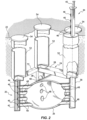
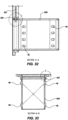
- the acoustic flow meter 20 is buried in the ground 22 ( Fig. 2 ) and includes a frame 24 which supports a pipe section 26. Pipe section 26 is adapted to be coupled to either end of the pipeline through which the flow rate is to be determined.
- Pipe section 26 has number of sound transmission tubes 48 which are mounted in a horizontal disposition as clearly shown in Figs. 2 and 3 .
- the sound transmission tubes 48 are typically cylindrical in shape and are made of an acoustically transmissive material which couples the aligned acoustic transducers 46 to the internal bore of the pipe section 26.
- the sound transmission tubes 48 are arranged to intersect the pipe section 26 at an angle ⁇ ( Fig. 5a ) to the direction of fluid flow 50.
- the preferred intersection angle ⁇ is 45 degrees, however other implementations could be manufactured with an intersection angle ⁇ between 0 and 90 degrees to suit geometry requirements of various applications.
- the sound transmission tubes 48 provide an acoustic path for the acoustic transducers 46 located within the flow meter cartridges 44. In Fig. 5a the sound transmission tubes 48 are hollow so that they contain the fluid within the pipe section 26 and the sound propagates through this fluid only. The sound transmission tubes 48 will contain still water and will not be in the path of the water flow.
- the sound transmission tubes 48 may be filled or plugged with a solid material of appropriate acoustic behaviour so that the pipe section 26 is completely sealed and the cartridges 44 may be retrieved while the pipe is operating under a positive or negative pressure without the requirement to seal access ports 52 against this pressure.
- the sound transmission tubes 48 could also be filled with water with a boundary interface (not shown) between the still water in the sound transmission tubes 48 and the flowing water. This interface would be made of a material of appropriate acoustic properties that enables the ready transmission of the acoustic signals.
- An advantage of this example with the closed sound transmission tubes 48 is that the internal bore of the pipe section 26 will be smooth and there will be no potential for clogging or trapping of debris in the pipe section 26 or the sound transmission tubes 48.
- a good acoustic coupling would be achieved between the acoustic transducers 46 contained within the cartridges 44 and the end faces of the sound transmission tubes 48 by employing a camming mechanism within the access ports 52 which would positively engage the acoustic transducers 46 against the faces of the sound transmission tubes 48.
- a simpler coupling mechanism can be achieved by filling access ports 52 with water or similar fluid which acoustically couples the transducers 46 contained within cartridges 44 to the end faces of the sound transmission tubes 48.
- the access ports 52 are a sealed well containing a fluid which couples the transducers 46 to the inner face of the sound transmission tubes 48.
- the access ports 52 are typically aligned vertically and accessed through sealed lids 54 at ground level. In some applications the access ports 52 might be aligned horizontally and accessed through wall mounted lids.
- the access ports may be installed at any other angle as the installation requires.
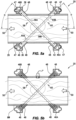
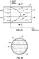
- acoustic transducers 46 Within a horizontal plane of the acoustic flow meter assembly 20 there are four acoustic transducers 46, which are arranged to provide two acoustic paths 58, 60 within each horizontal plane ( Figs. 5a and 5b ). As there are four acoustic transducers in each cartridge 44 there will be four horizontal planes 62, 64, 66 and 68 ( Figs. 6a and 6b ). These acoustic paths are at right angles to each other, and this arrangement eliminates cross flow errors as discussed in Section 13.1.3 of ASTM D5389-93(2007) Standard Test Method for Open-Channel Flow Measurement by Acoustic Velocity Meter Systems.
- the acoustic transducers 46 transmit a high frequency (in the kilohertz to megahertz range) sound pulse across the pipe section 26.
- the travel time of the acoustic signal is measured in a direction upstream to the direction of flow 50, and also in a direction downstream to the direction of flow 50 as seen in Figs 5a and 5b .
- the flow velocity creates a difference in the sound wave travel times in the upstream and downstream direction. This travel time difference is recorded and used to determine the average velocity of the fluid along the line of the acoustic path.
- the four measurement paths provide an average velocity of the fluid at four different planes 62-68 as shown in Fig. 6a .
- the velocity distribution within the pipe section 26 is then calculated from the velocities at each of the four planes 62-68 using a calibrated mathematical relationship.
- a water level sensor preferably an acoustic water level sensor 45
- each cartridge 44 includes a port, generally designated 47, for receiving and releasably retaining an acoustic water level sensor 45. It should be understood, however, that it is not essential for the water level sensor to be physically integrated into or with the associated cartridge 45, so long as a water level sensor is located at or in the vicinity of each cartridge 44.
- the water level sensors 45 function to provide an accurate measurement of the profile of the water surface at or in the vicinity of the overall flow meter assembly. Since a measurement is being made of the average velocity of flow of the water, then in order to be able to accurately compute the volumetric flow rate an accurate measurement of the cross-sectional area of flow at the location of the flow meter assembly is also required.
- acoustic transducers 46 may include any number and combination of acoustic transducers 46, as required, to realise other signal path configurations.
- the use of signal reflectors to replace some of the transducers in each measurement plane could also be used. It is not necessary to have four planes 62-68 across the acoustic flow meter assembly 20. Any number of planes may be used, for example, one or a plurality of planes. The planes need not be horizontal as shown in this example.
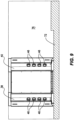
- Figs. 7 to 9 show the use of the acoustic flow meter assembly 20 in an open channel environment, typically used for water irrigation.
- a U-shaped channel 70 having a base 72 and sidewalls 74, 76 is used to control flow of irrigation water.
- the acoustic flow meter assembly 20 shown in Fig. 1 can be used but does not require the access ports 52 as the installation is not buried in the ground. Pipe section 26 is not required.
- This example is similar in construction to the previous example in that four retrievable cartridges 44 are provided. However the system can also be designed with one, two, three, or more retrievable cartridges 44, similar to the previous example. .
- the acoustic flow meter assembly 20 is manufactured under high tolerance and completely defines the geometry that the metered fluid passes through.
- This assembly 20 ensures that the fluid always passes through the same geometry through the body of the acoustic flow meter assembly 20 regardless of the geometry of the channel 70 into which it is installed.
- the cartridges 44 can be slidably removed and replaced without changing the geometry of the acoustic flow meter assembly 20.
- the cartridges 44 are each individually calibrated with a calibration referenced to their mounting points within the four hollow legs 36, 38, 40 and 42. This allows the cartridges 44 to be interchanged without effecting the calibration of the acoustic flow meter assembly 20.
- the acoustic transducer behaviour and geometry requirements are the same as described for the previous example.
- the acoustic flow meter assembly 20 of Figs. 7 to 9 includes a downstream control gate 80.
- the control gate 80 is a simple guillotine gate which is raised and lowered vertically and closes on a seal 82.
- the control gate 80 can be separate from the acoustic flow meter assembly 20, as shown, or could be integrated into a combined assembly.
- the control gate 80 forms an undershot gate which influences the surface velocity of the fluid 84 flowing through the acoustic flow meter assembly 20 and reduces the influence of the surrounding world on the flow profile passing through the acoustic flow meter assembly 20.
- the velocity is measured at a number of vertical elevations by acoustic transducers 46, and the velocity at each of these elevations is then fitted to a relationship which is used to interpolate the velocity at heights between the sampled elevations.
- the surface velocity of the fluid 84 is typically not measured because the elevation of the surface thereof varies during operation and so it is generally not possible to locate an acoustic transducer plane at the surface 86 of the fluid.
- the floor velocity is always zero, and the velocity at all elevations below the top transducer plane 62 can be interpolated from the measured values obtained in the planes above and below the elevation of interest.
- the unknown surface velocity means that the velocity at elevations above the top transducer plane 62 must be extrapolated based on assumptions of the shape of the velocity profile.
- This top section of the flow is typically where the greatest uncertainties in the velocity profile occur, as there is no information about the velocity at the surface. In worst case scenarios this velocity could be extremely high or even in a reverse direction to the flow due to surface influences such as wind.
- control gate 80 By locating control gate 80 downstream of acoustic flow meter assembly 20 and ensuring that the lower tip 88 of control gate 80 is always submerged, the control gate 80 maintains a laminar and streamlined flow profile which is free of turbulence. The velocity of the fluid will be zero in front of control gate 80.
- This flow profile is repeatable and may be characterised by a flow model which computes the flow rate using measurements of gate position and the fluid velocities measured by the acoustic transducer system.
- the repeatability of the flow profile passing under the control gate 80 is combined with the measured flow velocities at each of the sensor plane elevations 62, 64, 66 and 68 and is used to reduce the uncertainty in the estimation of the fluid's surface velocity through the body of the acoustic flow meter assembly 20.
- the influence of the undershot control gate 80 reduces the potential variation in the flow pattern through the acoustic flow meter assembly 20.
- Fig. 11 the guillotine control gate 80 of Fig. 10 is replaced with a tilt-lift type gate 90.
- the control gate 90 can be separate from the acoustic flow meter assembly 20, as shown, or could be integrated into a combined assembly.
- Gate 90 allows the gate to be in vertical disposition when closed on seal 82 and an angular or horizontal disposition when in the open position.
- Gate 90 is held between a frame 92 which includes a horizontal track 94 and a vertical track 96.
- Pins or rollers 98, 100 are located on the corners of gate 90 and are held captive in tracks 94, 96. The pins or rollers 98, 100 will move along their respective tracks to allow opening and closing of gate 90. Movement of gate 90 is controlled by a motor driven or hydraulic arm (not shown) coupled to the top 102 of gate 90. By pulling or pushing the top 102 of gate 90 the gate will be raised or lowered to act as an undershot gate.
- the tilt lift gate 90 allows for both a repeatable flow streamline for a given gate position as well as keeping the velocity of the fluid at the surface to a minimum. Both the above ensure minimal error in computing the flow for the segment between the sensors 48 in the top sensor plane elevation 62 and the water surface 84.
- the undershot gate 90 being located downstream creates a surface velocity distribution through the body of the acoustic flow meter assembly 20 meter that is more repeatable and predictable than would be the case if the undershot gate 90 were not present.
- the gate 90 forces the flow to be non-turbulent and laminar.
- the gate 90 allows creation of a flow computation algorithm which is a function of the gate position and the velocities measured by the acoustic transducers 46.
- the open channel and closed conduit implementations of the acoustic flow meter assembly 20 are supplied as a single assembly which completely defines its own geometry such that in-field commissioning of meter geometry parameters is not required.
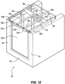
- Figs. 12 to 17 show a further variation of the tilt-lift gate 90 shown in Fig. 11 .
- gate 120 does not have the pins or rollers 98, 100 at both ends of gate 90 in Fig. 11 .
- the control gate 120 can be separate from the acoustic flow meter assembly 20 or could be integrated into a combined assembly, as shown. The integration of the control gate 120 and the acoustic flow meter assembly 20 will allow a drop in solution which has already been calibrated.
- Top 122 of gate 120 is pivotally mounted by brackets 124 and axle 126.
- the axle 126 runs in guiding tracks 128.
- Horizontally mounted arm members 130 are pivotally mounted to axle 126 and will allow gate 120 to be moved from a closed to an open position and vice versa.
- the arm members 130 can be moved by an electric motor or hydraulic means depending on requirements.
- the arm members 130 are cable driven by spools 132 which are coupled to an electric motor 134.
- a gear box 136 will drive the spools 132.
- the cables from spools 132 will be attached to the arm members 130 or axle 126.
- the positioning of the gate 120 is controlled by an extension arm 138 attached to the underside 140 of gate 120.
- Extension arm 138 has a pivot point 142 at its free end.
- the pivot point 142 is at a position that will result in a minimal force (actuation force) to open gate 120. This will result in a low cost actuation and drive train system 132-136.
- the preferred pivot point location is that of the line of the net resultant force when the gate is in the closed position, typically 2 3 the depth of water below the water surface level. This point represents the neutral axis about which the net forces above the axis equal the net forces below the axis.
- the force on the gate 120 is due to water pressure and which equals: ⁇ * g * h, at a given depth h below the water surface
- the pivot point is offset perpendicular from the underside 140 of gate 120. Pivot point 142 is constrained to move along a rail or slot 144 which is at a downward angle towards gate 120.
- the offset assists in providing a downward force when closing the gate from its fully open substantially horizontal position.
- the offset also ensures the gate side seals (not shown) do not cross the rail or slot 144 in order to avoid leakage around the side seals.
- the angle of the rail or slot 144 also assists with the downward force when closing gate 120 from its fully open substantially horizontal position.
- a seal 146 is provided on the free end edge and sides of the gate 120.
- the seal is in the form of a bulb seal which engages on a slightly raised face 148 on the base 72 and sides 74, 76 and of the U-shaped channel 70 when gate 120 is in the vertical i.e. closed position. Seal 146 will undergo minimal compression when in contact with the U-shaped channel 70.
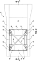
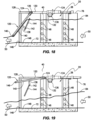
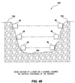
- Fig. 18 shows the situation of the downstream gate 120 backing up the water level 84 through the body of the acoustic flow meter under the same flow and water depth conditions as Fig. 19 which has no downstream obstruction. It can be seen that the gate 120 acts to maintain a deeper flow through the body of the meter, such that all transducers are submerged below the water surface. In Fig. 19 the water surface drops as the flow velocity increases through the body of the acoustic flow meter such that several of the transducers 48 are not submerged below the water surface.
- This key advantage discovered through fluid dynamic simulations causes the water to back-up in front of it in situations where there is no downstream tail water. This depth profile is problematic as many of the sensor paths will be above water and so not able to be used in the measurement.
- a partially open gate located downstream of the meter backs the water up so that it flows through the body of the meter at approximately constant depth such that more measurement paths can be used. This allows the flow meter to be used in hydraulic conditions which would otherwise not be compatible with metering using this approach.
- the angular position of sensor pairs 48 is not restricted to horizontal planes and preferred 45 degrees to the centreline.
- the sensor pairs 48 can be at angular orientation.
- the sensor 48 is not limited to a send and receive device with a matching pair. Many sensors could receive signals from the one transmit sensor.
- Figs. 1 to 6 the examples could be incorporated in-situ into an existing pipeline. Sound transmission tubes 48 could be tapped and welded onto an existing pipeline rather than providing a separate acoustic flow meter assembly 20 which is inserted into the pipeline. The assembly would include the cartridges 44 in a modified frame 24.
- acoustic transducers 46 In Figs. 1 to 19 the acoustic transducers 46 have been described together with their operation.
- the acoustic transducers 46 preferably work in opposing pairs.
- the acoustic flow meter assembly 20 measures the travel time of the acoustic signal in a direction upstream 58B, 60B to the direction of flow 50, and also in a direction downstream 58A, 60A to the direction of flow 50 as seen in Figs 5a and 5b .
- the flow velocity creates a difference in the sound wave travel times in the upstream and downstream direction. This travel time difference is recorded and used to determine the average velocity of the water along the line of the acoustic path.
- the time difference is recorded using transducers and circuitry which together have intrinsic time delays which add to the actual travel time of the acoustic signal. These transducer 46 and circuitry time delays must be subtracted from the recorded acoustic signal travel time so that the actual travel time of the acoustic signal may be determined.
- the transducer 46 and circuit time delays are typically measured in a calibration of the acoustic flow meter assembly 20, and characterized as a numerical constant which is subtracted from the measured acoustic signal travel time to calculate a best estimate of the actual acoustic signal travel time.
- Two constants could be determined by calibrating the acoustic signal travel time measurements in both the upstream and downstream directions. This is not necessary however, as the acoustic signal travel time in the upstream direction is subtracted from the acoustic signal travel time in the downstream direction, a single calibrated time delay constant is sufficient to calibrate the required system measurement.
- the upstream signal travel time is precisely equal to the downstream signal travel time.
- the measured travel times will not be identical. The difference in the measured travel times will reflect the different time delay characteristics in the circuitry used to measure the upstream and downstream travel times, and can be determined as a single numerical value at an instant in time by calibrating the measurement system under still water zero flow conditions.
- time delays contributed by the transducers 46 and the upstream and downstream measurement circuitry are not constant, but are a function of environmental influences such as temperature and pressure, and of electronic circuit conditions such as operating voltage and temperature. Changes in these time delays result from changes in temperature, pressure, operating voltages and other environmental disturbances. These changes result in a change to the calibration of the flow metering system 20 which results in errors in measuring the precise difference in acoustic signal travel times. This results in errors in the measurement of flow velocity, which are particularly significant to the measurement of low flow velocities.
- a self-calibrating measurement system which is capable of calibrating itself against a reference standard on every flow velocity measurement, thereby preventing errors in the measurement of the acoustic signal travel times.
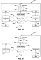
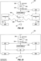
- a measurement system 200 is represented as a timer 202 which has a start input 204 and a stop input 206, together with several signal paths through which electrical information is transmitted.
- the drawings show only two transducers being represented in this measurement system 200 namely transducer 46A and transducer 46B from Figs. 5a and 5b for simplicity. All paired transducers 46 from Figs. 1 to 20 will be connected in the same manner.
- the acoustic signal travel time from transducer 46A to transducer 46B along path 58A is represented as T FLOW_A ⁇ B and the acoustic signal travel time from transducer 46B to transducer 46A along path 58B is represented as T FLOW_B ⁇ A .
- Fig. 21 shows only the signal path when measuring the acoustic signal travel time from transducer 46A to transducer 46B.
- This signal travel time is determined by sending a transmit signal 208 to transducer 46A.
- This transmit signal 208 has an initial signal characteristic which defines the start of the transmit signal. This signal characteristic is input to the timer 202 and defines the start of the time measurement.
- the transmit signal 208 is transmitted to transducer 46A which responds by transmitting an acoustic signal to transducer 46B.
- Transducer 46B converts this acoustic signal to an electrical signal which is input into the timer 202 and defines the end of the time measurement.
- the acoustic signal travel time from transducer 46B to transducer 46A is determined by sending a transmit signal 208 to transducer 46B.
- This transmit signal 208 has an initial signal characteristic which defines the start of the transmit signal. This signal characteristic is input to the timer 202 and defines the start of the time measurement.
- the transmit signal 208 is transmitted to transducer 46B which responds by transmitting an acoustic signal to transducer 46A.
- Transducer 46A converts this acoustic signal to an electrical signal which is input into the timer 202 and defines the end of the time measurement.
- the example provides additional measurements without using the transducers 46A, 46B. This aspect is shown in Fig. 23 .
- T BA _ Calibration ⁇ TB + ⁇ C + ⁇ RA
- the measurement process will be as follows:
- the electronic circuit delay times have been removed from the acoustic signal transit time measurements, and the difference in signal transit time measurements is determined precisely.
- the calibrations can occur in real time or the calibrations may be monitored at predetermined intervals.
- Another aspect provides a further method of measurement of velocity of fluid flowing in a pipe.
- acoustic transit time technology to measure the rate of flow in pipes it is common to use either a single path or cross path technique.
- the single path technique assumes a symmetrical velocity distribution around the centre line of the pipe with oppositely facing and offset top and bottom acoustic transducers.
- the cross path technique is used where the velocity distribution is non-symmetrical around the pipe centre line.
- two pairs of oppositely facing and offset top and bottom acoustic transducers are used and their acoustic paths cross the pipe centre line.
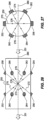
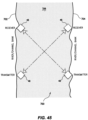
- Four pairs of acoustic transducers 252,254; 256,258; 260,262; and 264,266 are equi-spaced around pipe 250.
- the positioning of the acoustic transducers is not restricted to being equi-spaced but can be placed in positions to suit requirements.
- the number of pairs of acoustic transducers can vary but at least three pairs must be provided.
- the upstream and downstream acoustic paths 270-276 all cross at a central point 278 along the central axis 280 of pipe 250. Accordingly, measurements along the four paths 270-276 can be made to increase accuracy. If one of the acoustic transducers 252-266 fails, then measurements can still be made with the remaining acoustic transducers. The failure can be detected and the faulty acoustic transducer replaced at a convenient time.
- This aspect of the invention provides at least three single or cross paths located around the centre line 280 of pipe 250.
- This approach will provide at least three independent flow meters formed by the co-operating pairs of acoustic transducers on pipe 250. The result is to allow the real-time detection of the failure of any one of the independent flow meters, but also to be able to maintain flow measurement until the fault is corrected. To achieve this effect using other metering technologies, for example, magnetic flow meters, would require three meters to be installed in series along a section of pipe.
- a time of flight or transit time measuring apparatus is located immediately upstream of a slide or control gate 500.
- the control gate 500 may be of the type referred to in the present applicant's Australian Patent No. 2001283691 , as referred to and described earlier in this specification.
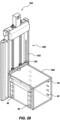
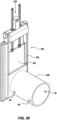
- the measurement apparatus will take the form of a conduit 600, of any cross-section but more particularly of either a circular, as in Fig. 29 , or a parallelepipedal as in Fig. 28 , cross-section, which conduit 600 will be associated with - either fixedly or removably - the frame of a flow or control gate 500.
- a control gate 500 to be located within a conduit, as for example an irrigation channel (not shown), the function of the control gate being to allow a controlled flow of water through the channel.
- the control gate 500 includes a gate leaf 501 which slides within a frame 502.
- Frame 502 has an outer frame member, which may be permanently secured to floor and sides of an irrigation channel or conduit and an internal frame member which slides within that outer frame member.
- the internal frame member may be connected to and separated from the external frame member with no requirement to undertake civil works on the floor and sides of the irrigation channel.
- This type of internal/external frame mechanism is further detailed in the specification of the present applicant's International (PCT) Patent Application No. PCT/AU2001/001036 .
- Gate leaf 501 may be raised or lowered by a lifting mechanism 503 of any known type, as for example that illustrated and described in the present applicant's International Patent Application No. PCT/AU2010/000115 . It should be understood, however, that the invention is not limited to usage only with such a flow or control gate.
- a typical installation would involve a control or flow gate (of any given type) with the associated measuring apparatus 600 attached, in any known manner and using any known means, to the upstream inlet of a conduit or pipe, located for example in a canal, reservoir or the like watercourse.
- conduit connection means at both upstream and downstream ends or sides of the overall flow meter assembly as referred to earlier in this specification.
- the conduit 500 has associated therewith acoustic transducers 46 for the generation of acoustic beams which traverse the flow through that conduit 500.
- the arrangement in accordance with the present invention relies for its operation on a derived relationship between the flow through the conduit and the transit time measurements of acoustic beams which traverse the fluid.
- the relationship further relies on the measurement inputs of water level (as determined by the level sensors) and gate position.
- PCT/AU2002/000230 the present applicant's International Patent Application No. PCT/AU2002/000230 .
- acoustic beams which traverse the flow can be singular or many, and can exhibit a variety of different orientations.
- preferred arrangements as shown in the drawings will include three (3) pairs of acoustic transducers 46 for the parallelepipedal conduit 600 of Fig. 28 and one (1) pair for the circular conduit 600 of Fig. 29 .
- the arrangement is such that the conduit 600 is substantially fixed within the channel, whilst the control gate leaf 501 is movable substantially vertically within that channel, whereby to allow for variation of flow through the conduit 600.
- the arrangement utilises a double seal 601, see in particular Figs. 33 to 36 , which runs the entire circumference of the gate 500. That double seal 601 ensures complete sealing of the conduit 600 from both upstream and downstream thereof, as well as external thereto.
- the gate 500 employs a flat face or surface on both the upstream and downstream sides of the leaf 501 to ensure position sealing through the full travel of the gate 500.
- Fig. 37 has a single divider 602 whilst Fig. 38 has a pair of dividers 602.
- the dividers 602 have a plurality of acoustic transducers 46 attached on either side which cooperate with the acoustic transducers 46 on the inner opposing walls of conduit 600.
- the acoustic path lengths f the embodiment shown in Fig. 28 will be reduced as the acoustic transducers of the embodiment shown in Fig. 37 will be between the divider 602 and the inner walls of conduit 600 on either side.
- Fig. 33 the acoustic path lengths f the embodiment shown in Fig. 28 will be reduced as the acoustic transducers of the embodiment shown in Fig. 37 will be between the divider 602 and the inner walls of conduit 600 on either side.
- the acoustic path lengths will be further reduced because the acoustic path lengths are between the divider 602 and the inner walls of conduit 600 on either side and between the dividers 602 in the middle of conduit 600. This reduced acoustic path length will allow a reduction in the length of conduit 600. It is possible to have further dividers 602 but the cost of the additional acoustic transducers 46 would be expensive and not justifiable.
- Figs. 39 and 40 there is shown a variation of the embodiment of Fig. 29 with dividers 602.
- the dividers 602 operate in the same manner as that described with respect to Figs. 37 and 38 . Again the resulting reduction in acoustic path length will allow a reduction in the length of conduit 600.
- Fig. 41 The embodiment shown in Fig. 41 is similar to the embodiment of Fig. 28 .
- Figs. 42 and 43 relate to the use of dividers 602 for the embodiment of Fig. 41 and operate identically to the embodiments of Figs. 37 and 38 previously discussed.
- Figs. 44 to 46 show a schematic drawing of a further measurement system in the form of an acoustic transit time flow meter designed to measure fluid flows 700 which does not require linked cabling to connect all acoustic transducers 46 to a central location.
- the measurement system 200 described in Figs. 20 to 25 requires cabling which traverses opposite sides of the open channel.
- the system shows a left river or channel bank 702 and an opposite right river or channel bank 704. Conventionally, cabling would be required to cross the river or channel bed 706 between banks 702, 704. It may not be feasible to dig up or cut into the river or channel bed 706 to lay the required cables.
- the cartridges 44A may contain the acoustic transducers 46 as previously described.
- the cartridge 44A contains the required electronics and processing circuitry and is powered by a solar panel 708.
- a telemetry radio 712 allows generation of RF signals which can be sent and received using data radio antenna 710. Data can also be sent to a central location for storage and further processing.
- Fig. 44 shows use of the transit time flow meter where the transit time flow meter measures flows by the standard transit time method.
- the flow meter consists of two or more cartridges 44A which provide their own power supply 708, a shared radio communications link, the acoustic transducers 46, and a synchronising radio signal which is used to synchronise the signal sampling system clock in each cartridge 44A.
- cartridges 44A are installed - one on either side of each bank 702, 704.
- Four cartridges 44A may also be installed as shown in Fig. 44 , two per side to provide the standard crossed-path metering arrangement. Further cartridge pairs may be used to provide additional velocity information within the flow channel.
- the cartridge pairs 44A act alternately as an acoustic transmitter and an acoustic receiver.
- cartridge 714 in the pair acts as a transmitter
- cartridge 716 acts as a receiver and receives the acoustic signal 718 transmitted by cartridge 714.
- Cartridge 714 records the time of the firing event in its high resolution timing circuitry
- cartridge 716 records the time of the receive event in its high resolution timing circuitry.
- the timing circuitry in each cartridge is a high speed binary counter, which is initialised to a zero value and then proceeds to count upwards. Each count in these counters is updated in a 10 pico-second period, and so a single counter increment represents a 10 pico-second duration.
- the transmit event is captured by circuitry in cartridge 714, and the timing count value at this instant is stored in a register in cartridge 714.
- the receive event is captured by circuitry in cartridge 716 and the timing count value at this instant is stored in a register in cartridge 716.
- the counter in cartridge 714 is not synchronised with the counter in cartridge 716, and so the time difference between the register value stored in cartridge 716 and cartridge 714 is indeterminate.
- an RF synchronisation pulse is transmitted from cartridge 714 to cartridge 716 prior to the firing pulse.
- This RF pulse travels between the two cartridges 714, 716 at the speed of light (3x10 8 m/s), meaning that the time elapsed for a cartridge spacing of 100 m is 333 ns.
- This RF pulse is captured by both timing systems in cartridges 714, 716 and provides a common time tag with which to refer the firing event and receive event within the two cartridge timing circuits.
- the acoustic transit time is then calculated by subtracting the firing event time from the receive event time.
- the cartridges 714, 716 then swap roles and the transmitter cartridge 714 becomes the receiver cartridge and vice-versa.
- the acoustic transit time in the reverse direction is then calculated, allowing the differential transit time to be recorded and used to deduce flow rate through the channel.
- Fig. 45 replaces the RF system of Fig. 44 with a laser system.
- a sync pulse laser radio 720 ( Fig. 47 ) could then be used as a substitute.
- the cartridge 44A shows both options but it is to be understood that the system can operate with only one of these options
Landscapes
- Physics & Mathematics (AREA)
- Engineering & Computer Science (AREA)
- Fluid Mechanics (AREA)
- General Physics & Mathematics (AREA)
- Structural Engineering (AREA)
- General Engineering & Computer Science (AREA)
- Mechanical Engineering (AREA)
- Electromagnetism (AREA)
- Civil Engineering (AREA)
- Measuring Volume Flow (AREA)
Claims (7)
- Hebetoranordnung (500), umfassend ein Torelement (501) und einen Rahmen (502), wobei das Torelement (501) in dem Rahmen (502) gleitfähig ist und das Torelement (501) aus einer geschlossenen bzw. offenen Konfiguration angehoben und/oder gesenkt werden kann, wobei sich die Hebetoranordnung (500) in einem offenen Fluidkanal befinden kann und weiter eine akustische Durchflussmessvorrichtung (600) zum Messen von Durchgangszeiten eines akustischen Signals durch ein Fluid, das durch die akustische Durchflussmessvorrichtung (600) strömt, umfasst, wobei der Rahmen (502) an und stromaufwärts der akustischen Durchflussmessvorrichtung (600) zum Messen von Durchgangszeiten von akustischen Signalen durch das Fluid befestigt ist, wobei die akustische Durchflussmessvorrichtung (600) die Form einer Leitung (600) mit einem oder mehreren gegenüberliegenden Paaren von akustischen Wandlern (46) aufweist, wobei der Rahmen (502) eine Doppeldichtung (601) enthält, die um seinen gesamten Umfang angeordnet ist, dadurch gekennzeichnet, dass die Hebetoranordnung (500) weiter mindestens drei Paare von akustischen Wandlern (252-266) umfasst, wobei sich jedes Paar der akustischen Wandler (252, 254) an gegenüberliegenden Seiten der Leitung (600) befindet und in Längsrichtung entlang der Leitung (600) versetzt ist, um einen stromaufwärts und stromabwärts liegenden Wandler (252, 254) bereitzustellen, wobei akustische Pfade jedes Paars von akustischen Wandlern (252-266) in Verwendung an einem Punkt (278) entlang der Achse der Leitung (600) schneiden, um Redundanz beim Messen eines Flusses durch die Leitung (600) bereitzustellen, sollte einer der akustischen Wandler (252-266) versagen.
- Anordnung nach Anspruch 1, wobei die Leitung (600) einen kreisförmigen oder parallelepipedförmigen Querschnitt aufweist.
- Anordnung nach Anspruch 2, wobei der Querschnitt quadratisch oder rechteckig ist.
- Anordnung nach einem der Ansprüche 1 bis 3, wobei das Torelement (501) und der Rahmen (502) im Wesentlichen vertikal ausgerichtet sind.
- Anordnung nach einem der Ansprüche 1 bis 3, wobei das Torelement (501) und der Rahmen (502) relativ zu der Leitung winkelig oder schräg sind.
- Anordnung nach Anspruch 1, wobei die Doppeldichtung (601) vollständige Dichtung der Leitung von stromaufwärts, stromabwärts und außen sicherstellt, um Dichtung über die gesamte Bewegung des Torelements (501) sicherzustellen.
- Anordnung nach Anspruch 1, wobei der eine oder die mehreren gegenüberliegenden akustischen Wandler (252, 254) diagonal zueinander ausgerichtet sind.
Priority Applications (1)
| Application Number | Priority Date | Filing Date | Title |
|---|---|---|---|
| EP25162789.9A EP4567383A3 (de) | 2009-08-18 | 2010-08-18 | Durchflussmesseranordnung, toranordnungen und verfahren zur durchflussmessung |
Applications Claiming Priority (4)
| Application Number | Priority Date | Filing Date | Title |
|---|---|---|---|
| AU2009903893A AU2009903893A0 (en) | 2009-08-18 | Flow meter assembly | |
| AU2009905149A AU2009905149A0 (en) | 2009-10-22 | Flow meter assembly | |
| AU2010902414A AU2010902414A0 (en) | 2010-06-02 | Flow meter assembly | |
| PCT/AU2010/001052 WO2011020143A1 (en) | 2009-08-18 | 2010-08-18 | Flow meter assembly, gate assemblies and methods of flow measurement |
Related Child Applications (2)
| Application Number | Title | Priority Date | Filing Date |
|---|---|---|---|
| EP25162789.9A Division EP4567383A3 (de) | 2009-08-18 | 2010-08-18 | Durchflussmesseranordnung, toranordnungen und verfahren zur durchflussmessung |
| EP25162789.9A Division-Into EP4567383A3 (de) | 2009-08-18 | 2010-08-18 | Durchflussmesseranordnung, toranordnungen und verfahren zur durchflussmessung |
Publications (3)
| Publication Number | Publication Date |
|---|---|
| EP2467680A1 EP2467680A1 (de) | 2012-06-27 |
| EP2467680A4 EP2467680A4 (de) | 2017-12-27 |
| EP2467680B1 true EP2467680B1 (de) | 2025-04-16 |
Family
ID=43606468
Family Applications (2)
| Application Number | Title | Priority Date | Filing Date |
|---|---|---|---|
| EP10809359.2A Active EP2467680B1 (de) | 2009-08-18 | 2010-08-18 | Flussmesseranordnung, toranordnungen dafür und flussmessverfahren |
| EP25162789.9A Pending EP4567383A3 (de) | 2009-08-18 | 2010-08-18 | Durchflussmesseranordnung, toranordnungen und verfahren zur durchflussmessung |
Family Applications After (1)
| Application Number | Title | Priority Date | Filing Date |
|---|---|---|---|
| EP25162789.9A Pending EP4567383A3 (de) | 2009-08-18 | 2010-08-18 | Durchflussmesseranordnung, toranordnungen und verfahren zur durchflussmessung |
Country Status (11)
| Country | Link |
|---|---|
| US (5) | US8474327B2 (de) |
| EP (2) | EP2467680B1 (de) |
| CN (3) | CN102575950A (de) |
| AU (1) | AU2010283959A1 (de) |
| BR (1) | BR112012003537B1 (de) |
| CA (2) | CA2948307A1 (de) |
| CL (1) | CL2012000414A1 (de) |
| MX (5) | MX344270B (de) |
| NZ (4) | NZ613848A (de) |
| WO (1) | WO2011020143A1 (de) |
| ZA (2) | ZA201201428B (de) |
Families Citing this family (47)
| Publication number | Priority date | Publication date | Assignee | Title |
|---|---|---|---|---|
| US20140069207A1 (en) | 2011-03-18 | 2014-03-13 | Soneter, LLC | Methods and apparatus for fluid flow measurement |
| CA3052881C (en) * | 2011-04-01 | 2022-09-06 | Rubicon Research Pty Ltd | Actuation and valve mechanism |
| US8438936B2 (en) | 2011-06-03 | 2013-05-14 | General Electric Company | Sensor assembly including a collar for mounting sensors to a pipeline |
| WO2013165314A1 (en) * | 2012-05-04 | 2013-11-07 | Dhi Water & Environment (S) Pte Ltd | A flow meter system |
| CN107101677B (zh) | 2012-05-30 | 2020-01-17 | 鲁比康研究有限公司 | 流体网中的泥沙控制 |
| NZ724844A (en) * | 2012-07-13 | 2017-09-29 | Rubicon Res Pty Ltd | Pipe flow meters |
| CN102798419A (zh) * | 2012-08-15 | 2012-11-28 | 江苏迈拓智能仪表有限公司 | 一种超声波流量传感器 |
| IN2015DN03971A (de) | 2012-10-11 | 2015-10-02 | Rubicon Res Pty Ltd | |
| CA2838446C (en) * | 2013-01-04 | 2017-02-21 | Schlagel, Inc. | Gate with variable gate control for handling agricultural granular materials |
| US10059513B1 (en) | 2013-01-04 | 2018-08-28 | Schlagel, Inc. | Gate with anti-fouling proximity indicators for handling agricultural granular materials |
| US9091576B2 (en) * | 2013-01-14 | 2015-07-28 | Cameron International Corporation | Deployable ultrasonic flow meter that is inserted through a gate valve slot, method and apparatus |
| US9612141B2 (en) * | 2013-04-25 | 2017-04-04 | Woojin Inc. | Ultrasonic flow measurement system |
| US9080908B2 (en) * | 2013-07-24 | 2015-07-14 | Jesse Yoder | Flowmeter design for large diameter pipes |
| WO2015031954A1 (en) | 2013-09-04 | 2015-03-12 | Rubicon Research Pty Ltd | Method of demand management and control of fluid pipe networks |
| US9494454B2 (en) * | 2013-12-06 | 2016-11-15 | Joseph Baumoel | Phase controlled variable angle ultrasonic flow meter |
| AU2015286219A1 (en) * | 2014-07-06 | 2016-12-22 | Rubicon Research Pty Ltd | Measurement of flow through pipelines |
| CN104596601B (zh) * | 2014-12-25 | 2018-08-03 | 重庆川仪自动化股份有限公司 | 八声道超声波流量计传感器 |
| US10184221B2 (en) | 2015-02-06 | 2019-01-22 | Norman Paul Watson | Water control system and method for water management |
| US10053829B2 (en) | 2015-02-06 | 2018-08-21 | Norman Paul Watson | Flashboard riser system and method for water management |
| US9624637B2 (en) * | 2015-04-08 | 2017-04-18 | Smart Vent Products, Inc. | Flood vent |
| US9752907B2 (en) | 2015-04-14 | 2017-09-05 | Joseph Baumoel | Phase controlled variable angle ultrasonic flow meter |
| CA2895361C (en) * | 2015-06-19 | 2023-08-01 | Accutron Instruments Inc. | Method and system for ultrasonic airflow measurements |
| NL2015247B1 (en) * | 2015-07-31 | 2017-02-20 | Berkin Bv | A method for determining a flow rate for a fluid in a flow tube of a flow measurement system, as well as a corresponding flow measurement system. |
| DE102016006244A1 (de) | 2016-01-14 | 2017-07-20 | Diehl Metering Gmbh | Ultraschallfluidzähler sowie Verfahren zur Durchfluss- und/oder Volumenbestimmung eines strömenden Mediums |
| CN105780717B (zh) * | 2016-03-24 | 2018-03-06 | 华北水利水电大学 | 一种用于多沙渠道的闸门量水方法 |
| CN105625284A (zh) * | 2016-03-25 | 2016-06-01 | 山东省水利科学研究院 | 一种闸门控制与测流装置 |
| CN105804016B (zh) * | 2016-04-05 | 2017-11-07 | 河海大学 | 一种适合于水利工程上用的城市拦河闸 |
| RU2619819C1 (ru) * | 2016-05-23 | 2017-05-18 | Общество с ограниченной ответственностью "Синтез НПФ" | Устройство фиксации рентгеновского аппарата на трубе |
| CN108020272A (zh) * | 2016-11-03 | 2018-05-11 | 钛能科技股份有限公司 | 一种明渠过闸流量在线监测装置 |
| CR20190378A (es) | 2017-01-17 | 2019-11-19 | Rubicon Res Pty Ltd | Medición de flujo |
| WO2018162340A1 (en) * | 2017-03-07 | 2018-09-13 | Abb Schweiz Ag | Apparatus and method for measuring the flow velocity of a fluid in a pipe |
| US10126155B1 (en) * | 2017-08-25 | 2018-11-13 | Saudi Arabian Oil Company | Multi-layer flow and level visualizer |
| EP3450930A1 (de) * | 2017-08-29 | 2019-03-06 | Nederlandse Organisatie voor toegepast- natuurwetenschappelijk onderzoek TNO | Akustischen messung einer flüssigkeitsströmung |
| CN108775936B (zh) * | 2018-03-23 | 2020-04-10 | 中国航天系统科学与工程研究院 | 一种流量计量装置、计量方法及测控一体化闸门系统 |
| CN108387279B (zh) * | 2018-04-09 | 2024-05-24 | 河北科鼎智能科技有限公司 | 一种基于声波矩阵的液体流量测量装置及测量方法 |
| CN108871477A (zh) * | 2018-06-05 | 2018-11-23 | 北京华水仪表系统有限公司 | 超声波明渠流量计 |
| US11274952B2 (en) * | 2018-11-16 | 2022-03-15 | Levitronix Gmbh | Ultrasonic measuring device for ultrasonic measurement on a flowing fluid |
| CN109297551B (zh) * | 2018-11-26 | 2020-11-24 | 浙江清环智慧科技有限公司 | 一种管网流量的测量方法及系统 |
| CN109443469A (zh) * | 2018-12-26 | 2019-03-08 | 安徽金大仪器有限公司 | 一种智能节能型电子水表 |
| US10588273B1 (en) * | 2019-04-24 | 2020-03-17 | Joshua Bishop | Flood irrigation apparatus |
| WO2021054977A1 (en) * | 2019-09-20 | 2021-03-25 | Halliburton Energy Services, Inc. | Acoustic production flow measurements |
| WO2021072496A1 (en) * | 2019-10-15 | 2021-04-22 | Rubicon Research Pty Ltd | Overshot and undershot control gate |
| DE102020116181A1 (de) * | 2020-06-18 | 2021-12-23 | Endress+Hauser Flowtec Ag | Clamp-On-Ultraschall-Durchflussmessgerät |
| JP7475047B2 (ja) | 2020-11-09 | 2024-04-26 | 株式会社アイシーティー | 超音波流量計 |
| CA3213372A1 (en) | 2021-03-26 | 2022-09-29 | Capta Hydro Spa | Vandal-proof installation system for the monitoring of physical variables in water, comprising: a first member; a second member; a third member and a fourth member; where the first member comprises a plurality of compartments for housing a plurality of devices. assembly metho |
| US20220364902A1 (en) * | 2021-05-07 | 2022-11-17 | StormSensor Inc. | Calibrating fluid flow measurements in fluid flow systems |
| CN115326150A (zh) * | 2022-08-11 | 2022-11-11 | 北京奥特美克科技股份有限公司 | 一种渠道的流量测量装置 |
Family Cites Families (47)
| Publication number | Priority date | Publication date | Assignee | Title |
|---|---|---|---|---|
| GB465004A (en) * | 1935-12-23 | 1937-04-29 | William R Yendall | Improvements in overhead-housed sliding doors |
| GB692075A (en) * | 1951-07-10 | 1953-05-27 | Keith Halliwell | Improved door control mechanism |
| US3771117A (en) * | 1972-03-01 | 1973-11-06 | Westinghouse Electric Corp | Transducer installation |
| US3869915A (en) * | 1973-01-23 | 1975-03-11 | Joseph Baumoel | Digital flowmeter |
| US4162630A (en) * | 1976-09-20 | 1979-07-31 | University Of Utah | Measurement and reconstruction of three-dimensional fluid flow |
| JPS5829854B2 (ja) * | 1977-07-26 | 1983-06-25 | 富士電機株式会社 | 超音波式測定装置 |
| FR2443050A1 (fr) * | 1978-11-29 | 1980-06-27 | Framatome Sa | Dispositif de mesure d'un parametre relatif a un fluide en ecoulement dans une canalisation |
| US4350916A (en) | 1980-06-27 | 1982-09-21 | Rockwell International Corporation | Surface acoustic wave device having buried transducer |
| US4483200A (en) * | 1981-01-19 | 1984-11-20 | Anima Corporation | Thermal pulse flowmeter |
| US4462261A (en) * | 1982-04-27 | 1984-07-31 | The Babcock & Wilcox Company | Mass and velocity flowmeter |
| JPS62247216A (ja) * | 1986-04-21 | 1987-10-28 | Nippon N U S Kk | 超音波により浮遊物を含む流体の流量測定方法 |
| US4726709A (en) * | 1986-09-23 | 1988-02-23 | Camille Labelle | Sealing assemblies |
| US4762012A (en) * | 1987-01-29 | 1988-08-09 | Manning Technologies, Inc. | Universal upstream-downstream flowmeter tester |
| US5179862A (en) * | 1990-06-29 | 1993-01-19 | Panametrics, Inc. | Snap-on flow measurement system |
| JPH04361121A (ja) * | 1991-06-06 | 1992-12-14 | Kaijo Corp | 3次元型流体流速計 |
| JPH052429A (ja) * | 1991-06-24 | 1993-01-08 | Ishikawajima Harima Heavy Ind Co Ltd | 流量調節ゲートの制御方法及び装置 |
| GB9119742D0 (en) * | 1991-09-16 | 1991-10-30 | British Gas Plc | Measurement system |
| US7159472B1 (en) * | 1995-03-31 | 2007-01-09 | Cameron International Corporation | Apparatus for determining fluid flow |
| US5719329B1 (en) * | 1995-12-28 | 1999-11-16 | Univ Ohio | Ultrasonic measuring system and method of operation |
| EP0800062A3 (de) * | 1996-04-04 | 1998-04-15 | Georg Fischer Rohrleitungssysteme AG | Vorrichtung zur Messung der Strömungsgeschwindigkeit eines Fluides |
| FR2781047B1 (fr) * | 1998-07-10 | 2000-09-01 | Faure Herman | Debitmetre a ultrasons multicorde |
| JP2000346686A (ja) * | 1999-06-08 | 2000-12-15 | Fuji Electric Co Ltd | 超音波流量計 |
| US6327915B1 (en) * | 1999-06-30 | 2001-12-11 | Micro Motion, Inc. | Straight tube Coriolis flowmeter |
| US6487916B1 (en) * | 2000-02-02 | 2002-12-03 | Bechtel Bxwt Idaho, Llc | Ultrasonic flow metering system |
| KR100349504B1 (ko) * | 2000-04-24 | 2002-08-21 | 주식회사 창민테크 | 초음파 유속 측정장치 |
| DE60128702T2 (de) | 2000-08-21 | 2008-01-31 | Rubicon Research Pty Ltd. | Kontrollschieber |
| AUPR353801A0 (en) | 2001-03-02 | 2001-03-29 | Rubicon Systems Australia Pty Ltd | Fluid regulation |
| DE20122896U1 (de) * | 2001-09-14 | 2009-07-16 | Sick Ag | Messaufnehmer und Vorrichtung zum Messen der Strömungsgeschwindigkeit und/oder des Durchflusses eines Fluids |
| JP4424936B2 (ja) * | 2003-07-28 | 2010-03-03 | パナソニック株式会社 | 流路における流量均一化構造および流量計測装置 |
| US6895825B1 (en) * | 2004-01-29 | 2005-05-24 | The Boeing Company | Ultrasonic transducer assembly for monitoring a fluid flowing through a duct |
| CN1273689C (zh) * | 2004-04-21 | 2006-09-06 | 余姚市耀鑫给排水设备有限公司 | 可倾斜调节闸门 |
| US7044000B2 (en) | 2004-09-22 | 2006-05-16 | Murray F Feller | Ultrasonic flow sensor using quasi-helical beam |
| DE102005003398A1 (de) * | 2005-01-24 | 2006-08-03 | Endress + Hauser Flowtec Ag | Vorrichtung zur Bestimmung und/oder Überwachung des Volumen- und/oder Massendurchflusses |
| DE102006001074B4 (de) * | 2006-01-09 | 2009-09-24 | Asi Aquasound Instruments Gmbh | Ultraschall-Durchflußmeßsystem zum Messen eines Durchflusses in einem Gewässer und Verfahren |
| KR100749721B1 (ko) * | 2006-04-24 | 2007-08-21 | 한상관 | 대용량 저장용 슬라이딩 자동보 수문 |
| US7481114B2 (en) * | 2006-07-13 | 2009-01-27 | Lynnworth Lawrence C | Noninvasive measurement of fluid characteristics using reversibly deformed conduit |
| CN200992701Y (zh) * | 2006-12-19 | 2007-12-19 | 上海勘测设计研究院 | 单液压缸悬挂闸门 |
| GB0703250D0 (en) * | 2007-02-20 | 2007-03-28 | Ge Healthcare Bio Sciences Ab | Ultrasonic flow meter |
| DE102008019992B4 (de) * | 2008-04-21 | 2010-07-01 | Mib Gmbh Messtechnik Und Industrieberatung | Ultraschall-Messanordnung |
| JP4361121B1 (ja) | 2008-05-30 | 2009-11-11 | 株式会社エヌ・ティ・ティ・ドコモ | 移動局 |
| CN201269765Y (zh) * | 2008-08-27 | 2009-07-08 | 威海市天罡仪表有限公司 | 超声流量计 |
| DE102008055165A1 (de) * | 2008-12-29 | 2010-07-01 | Endress + Hauser Flowtec Ag | Messrohr eines Messsystems zur Bestimmung und/oder Überwachung des Durchflusses eines Messmediums durch das Messrohr mittels Ultraschall |
| WO2010088731A1 (en) | 2009-02-05 | 2010-08-12 | Rubicon Research Pty Ltd | Undershot sluice gate |
| EP2444781A1 (de) * | 2010-10-19 | 2012-04-25 | SICK Engineering GmbH | Ultraschallmessung von Strömungsgeschwindigkeit |
| US8544343B2 (en) * | 2010-11-19 | 2013-10-01 | Cameron International Corporation | Chordal gas flowmeter with transducers installed outside the pressure boundary |
| US8997848B2 (en) * | 2011-03-02 | 2015-04-07 | Cameron International Corporation | Pressure balanced ultrasonic flowmeter |
| US8974114B2 (en) * | 2012-05-02 | 2015-03-10 | Daniel Measurement And Control, Inc. | Temperature verification for ultrasonic flow meters |
-
2010
- 2010-08-18 BR BR112012003537-1A patent/BR112012003537B1/pt active IP Right Grant
- 2010-08-18 CN CN2010800469368A patent/CN102575950A/zh active Pending
- 2010-08-18 MX MX2016002916A patent/MX344270B/es unknown
- 2010-08-18 NZ NZ61384810A patent/NZ613848A/en not_active IP Right Cessation
- 2010-08-18 WO PCT/AU2010/001052 patent/WO2011020143A1/en not_active Ceased
- 2010-08-18 CN CN201410186961.6A patent/CN104075757A/zh active Pending
- 2010-08-18 NZ NZ598472A patent/NZ598472A/en unknown
- 2010-08-18 MX MX2012002121A patent/MX2012002121A/es active IP Right Grant
- 2010-08-18 MX MX2017003922A patent/MX364336B/es unknown
- 2010-08-18 CA CA2948307A patent/CA2948307A1/en not_active Abandoned
- 2010-08-18 MX MX2014009668A patent/MX341582B/es unknown
- 2010-08-18 NZ NZ705352A patent/NZ705352A/en not_active IP Right Cessation
- 2010-08-18 EP EP10809359.2A patent/EP2467680B1/de active Active
- 2010-08-18 CN CN201710407744.9A patent/CN107356296A/zh active Pending
- 2010-08-18 MX MX2016002914A patent/MX346622B/es unknown
- 2010-08-18 EP EP25162789.9A patent/EP4567383A3/de active Pending
- 2010-08-18 NZ NZ704287A patent/NZ704287A/en not_active IP Right Cessation
- 2010-08-18 CA CA2771310A patent/CA2771310C/en active Active
- 2010-08-18 AU AU2010283959A patent/AU2010283959A1/en not_active Abandoned
-
2012
- 2012-02-17 CL CL2012000414A patent/CL2012000414A1/es unknown
- 2012-02-17 US US13/399,957 patent/US8474327B2/en active Active
- 2012-02-27 ZA ZA2012/01428A patent/ZA201201428B/en unknown
-
2013
- 2013-04-25 US US13/870,857 patent/US8893560B2/en not_active Expired - Fee Related
- 2013-08-01 ZA ZA2013/05813A patent/ZA201305813B/en unknown
-
2014
- 2014-08-04 US US14/451,017 patent/US9593972B2/en not_active Expired - Fee Related
- 2014-11-25 US US14/553,963 patent/US9261390B2/en not_active Expired - Fee Related
-
2017
- 2017-01-20 US US15/411,545 patent/US9804008B2/en active Active
Also Published As
Similar Documents
| Publication | Publication Date | Title |
|---|---|---|
| EP2467680B1 (de) | Flussmesseranordnung, toranordnungen dafür und flussmessverfahren | |
| EP2906913B1 (de) | Flussmessung | |
| EP2511676B1 (de) | Eichvorrichtung für kleine Mengen und Verfahren zur Bereitstellung variabler Volumenkalibrierung | |
| AU2017203457B2 (en) | Flow meter assembly | |
| US20170153132A1 (en) | Measurement of flow through pipelines | |
| WO2009037501A1 (en) | Measurement of flow in a channel | |
| CN202216742U (zh) | 双通道法超声流量计时间差检测装置 | |
| Laenen | Acoustic velocity meter systems | |
| Simões et al. | Traceability and measurement uncertainty of non-removable field flowmeters using clamp-on ultrasonic flowmeters as reference | |
| CN114509135A (zh) | 明渠流量计在线校准装置 | |
| CN210268742U (zh) | 一种用于宽浅式明渠水流流量测量的孔口出流装置 | |
| CN218211469U (zh) | 一种隧道涌水监测装置 | |
| DE102005032132A1 (de) | Vorrichtung zur positionsabhängigen Detektion einer Leckage in einem verdeckten, von außen unzugänglichen Rohrleitungssystem | |
| Ashley et al. | Flow and sediment movement monitoring in large sewers | |
| Ward et al. | Upgrading the Flow Measurement System at the Tehama Colusa Canal Authority | |
| Simpson et al. | Techniques for accurate estimation of net discharge in a tidal channel | |
| Bryant et al. | Overview and Modernization of the 1.5 and 3 m Flumes | |
| Kyser | Hydraulic; ind Technical Realities of Flow Monitoring for Sanitary Sewer Overflows | |
| Styles | Doppler Flow Meters for Turnouts |
Legal Events
| Date | Code | Title | Description |
|---|---|---|---|
| PUAI | Public reference made under article 153(3) epc to a published international application that has entered the european phase |
Free format text: ORIGINAL CODE: 0009012 |
|
| 17P | Request for examination filed |
Effective date: 20120314 |
|
| AK | Designated contracting states |
Kind code of ref document: A1 Designated state(s): AL AT BE BG CH CY CZ DE DK EE ES FI FR GB GR HR HU IE IS IT LI LT LU LV MC MK MT NL NO PL PT RO SE SI SK SM TR |
|
| DAX | Request for extension of the european patent (deleted) | ||
| RA4 | Supplementary search report drawn up and despatched (corrected) |
Effective date: 20171123 |
|
| RIC1 | Information provided on ipc code assigned before grant |
Ipc: E05F 15/00 20150101ALI20171117BHEP Ipc: E02B 13/02 20060101ALI20171117BHEP Ipc: E02B 7/26 20060101ALI20171117BHEP Ipc: G12B 9/00 20060101ALI20171117BHEP Ipc: E02B 7/40 20060101ALI20171117BHEP Ipc: E05D 15/48 20060101ALI20171117BHEP Ipc: G01F 1/66 20060101AFI20171117BHEP Ipc: G01P 5/24 20060101ALI20171117BHEP Ipc: E02B 7/28 20060101ALI20171117BHEP Ipc: G01F 1/00 20060101ALI20171117BHEP |
|
| STAA | Information on the status of an ep patent application or granted ep patent |
Free format text: STATUS: EXAMINATION IS IN PROGRESS |
|
| 17Q | First examination report despatched |
Effective date: 20210430 |
|
| P01 | Opt-out of the competence of the unified patent court (upc) registered |
Effective date: 20230602 |
|
| GRAP | Despatch of communication of intention to grant a patent |
Free format text: ORIGINAL CODE: EPIDOSNIGR1 |
|
| STAA | Information on the status of an ep patent application or granted ep patent |
Free format text: STATUS: GRANT OF PATENT IS INTENDED |
|
| RIC1 | Information provided on ipc code assigned before grant |
Ipc: G01F 1/667 20220101ALI20241114BHEP Ipc: G01F 1/002 20220101ALI20241114BHEP Ipc: G01P 5/24 20060101ALI20241114BHEP Ipc: G12B 9/00 20060101ALI20241114BHEP Ipc: E02B 7/26 20060101ALI20241114BHEP Ipc: E02B 7/40 20060101ALI20241114BHEP Ipc: E02B 13/02 20060101ALI20241114BHEP Ipc: G01F 1/00 20060101ALI20241114BHEP Ipc: E02B 7/28 20060101ALI20241114BHEP Ipc: E05F 15/00 20060101ALI20241114BHEP Ipc: E05D 15/48 20060101ALI20241114BHEP Ipc: G01F 1/66 20060101AFI20241114BHEP |
|
| INTG | Intention to grant announced |
Effective date: 20241128 |
|
| GRAS | Grant fee paid |
Free format text: ORIGINAL CODE: EPIDOSNIGR3 |
|
| GRAA | (expected) grant |
Free format text: ORIGINAL CODE: 0009210 |
|
| STAA | Information on the status of an ep patent application or granted ep patent |
Free format text: STATUS: THE PATENT HAS BEEN GRANTED |
|
| AK | Designated contracting states |
Kind code of ref document: B1 Designated state(s): AL AT BE BG CH CY CZ DE DK EE ES FI FR GB GR HR HU IE IS IT LI LT LU LV MC MK MT NL NO PL PT RO SE SI SK SM TR |
|
| REG | Reference to a national code |
Ref country code: GB Ref legal event code: FG4D |
|
| REG | Reference to a national code |
Ref country code: CH Ref legal event code: EP Ref country code: DE Ref legal event code: R096 Ref document number: 602010069726 Country of ref document: DE |
|
| REG | Reference to a national code |
Ref country code: IE Ref legal event code: FG4D |
|
| REG | Reference to a national code |
Ref country code: NL Ref legal event code: MP Effective date: 20250416 |
|
| PG25 | Lapsed in a contracting state [announced via postgrant information from national office to epo] |
Ref country code: NL Free format text: LAPSE BECAUSE OF FAILURE TO SUBMIT A TRANSLATION OF THE DESCRIPTION OR TO PAY THE FEE WITHIN THE PRESCRIBED TIME-LIMIT Effective date: 20250416 |
|
| REG | Reference to a national code |
Ref country code: AT Ref legal event code: MK05 Ref document number: 1785965 Country of ref document: AT Kind code of ref document: T Effective date: 20250416 |
|
| PG25 | Lapsed in a contracting state [announced via postgrant information from national office to epo] |
Ref country code: PT Free format text: LAPSE BECAUSE OF FAILURE TO SUBMIT A TRANSLATION OF THE DESCRIPTION OR TO PAY THE FEE WITHIN THE PRESCRIBED TIME-LIMIT Effective date: 20250818 Ref country code: FI Free format text: LAPSE BECAUSE OF FAILURE TO SUBMIT A TRANSLATION OF THE DESCRIPTION OR TO PAY THE FEE WITHIN THE PRESCRIBED TIME-LIMIT Effective date: 20250416 Ref country code: ES Free format text: LAPSE BECAUSE OF FAILURE TO SUBMIT A TRANSLATION OF THE DESCRIPTION OR TO PAY THE FEE WITHIN THE PRESCRIBED TIME-LIMIT Effective date: 20250416 |
|
| REG | Reference to a national code |
Ref country code: LT Ref legal event code: MG9D |
|
| PG25 | Lapsed in a contracting state [announced via postgrant information from national office to epo] |
Ref country code: GR Free format text: LAPSE BECAUSE OF FAILURE TO SUBMIT A TRANSLATION OF THE DESCRIPTION OR TO PAY THE FEE WITHIN THE PRESCRIBED TIME-LIMIT Effective date: 20250717 Ref country code: NO Free format text: LAPSE BECAUSE OF FAILURE TO SUBMIT A TRANSLATION OF THE DESCRIPTION OR TO PAY THE FEE WITHIN THE PRESCRIBED TIME-LIMIT Effective date: 20250716 |
|
| PG25 | Lapsed in a contracting state [announced via postgrant information from national office to epo] |
Ref country code: PL Free format text: LAPSE BECAUSE OF FAILURE TO SUBMIT A TRANSLATION OF THE DESCRIPTION OR TO PAY THE FEE WITHIN THE PRESCRIBED TIME-LIMIT Effective date: 20250416 |
|
| PG25 | Lapsed in a contracting state [announced via postgrant information from national office to epo] |
Ref country code: BG Free format text: LAPSE BECAUSE OF FAILURE TO SUBMIT A TRANSLATION OF THE DESCRIPTION OR TO PAY THE FEE WITHIN THE PRESCRIBED TIME-LIMIT Effective date: 20250416 |
|
| PG25 | Lapsed in a contracting state [announced via postgrant information from national office to epo] |
Ref country code: HR Free format text: LAPSE BECAUSE OF FAILURE TO SUBMIT A TRANSLATION OF THE DESCRIPTION OR TO PAY THE FEE WITHIN THE PRESCRIBED TIME-LIMIT Effective date: 20250416 |
|
| PG25 | Lapsed in a contracting state [announced via postgrant information from national office to epo] |
Ref country code: AT Free format text: LAPSE BECAUSE OF FAILURE TO SUBMIT A TRANSLATION OF THE DESCRIPTION OR TO PAY THE FEE WITHIN THE PRESCRIBED TIME-LIMIT Effective date: 20250416 |
|
| PG25 | Lapsed in a contracting state [announced via postgrant information from national office to epo] |
Ref country code: IS Free format text: LAPSE BECAUSE OF FAILURE TO SUBMIT A TRANSLATION OF THE DESCRIPTION OR TO PAY THE FEE WITHIN THE PRESCRIBED TIME-LIMIT Effective date: 20250816 |
|
| PG25 | Lapsed in a contracting state [announced via postgrant information from national office to epo] |
Ref country code: LV Free format text: LAPSE BECAUSE OF FAILURE TO SUBMIT A TRANSLATION OF THE DESCRIPTION OR TO PAY THE FEE WITHIN THE PRESCRIBED TIME-LIMIT Effective date: 20250416 |
|
| PG25 | Lapsed in a contracting state [announced via postgrant information from national office to epo] |
Ref country code: SM Free format text: LAPSE BECAUSE OF FAILURE TO SUBMIT A TRANSLATION OF THE DESCRIPTION OR TO PAY THE FEE WITHIN THE PRESCRIBED TIME-LIMIT Effective date: 20250416 Ref country code: DK Free format text: LAPSE BECAUSE OF FAILURE TO SUBMIT A TRANSLATION OF THE DESCRIPTION OR TO PAY THE FEE WITHIN THE PRESCRIBED TIME-LIMIT Effective date: 20250416 |
|
| REG | Reference to a national code |
Ref country code: DE Ref legal event code: R097 Ref document number: 602010069726 Country of ref document: DE |
|
| PG25 | Lapsed in a contracting state [announced via postgrant information from national office to epo] |
Ref country code: CZ Free format text: LAPSE BECAUSE OF FAILURE TO SUBMIT A TRANSLATION OF THE DESCRIPTION OR TO PAY THE FEE WITHIN THE PRESCRIBED TIME-LIMIT Effective date: 20250416 |
|
| PG25 | Lapsed in a contracting state [announced via postgrant information from national office to epo] |
Ref country code: EE Free format text: LAPSE BECAUSE OF FAILURE TO SUBMIT A TRANSLATION OF THE DESCRIPTION OR TO PAY THE FEE WITHIN THE PRESCRIBED TIME-LIMIT Effective date: 20250416 |
|
| PG25 | Lapsed in a contracting state [announced via postgrant information from national office to epo] |
Ref country code: RO Free format text: LAPSE BECAUSE OF FAILURE TO SUBMIT A TRANSLATION OF THE DESCRIPTION OR TO PAY THE FEE WITHIN THE PRESCRIBED TIME-LIMIT Effective date: 20250416 Ref country code: SK Free format text: LAPSE BECAUSE OF FAILURE TO SUBMIT A TRANSLATION OF THE DESCRIPTION OR TO PAY THE FEE WITHIN THE PRESCRIBED TIME-LIMIT Effective date: 20250416 |
|
| PG25 | Lapsed in a contracting state [announced via postgrant information from national office to epo] |
Ref country code: IT Free format text: LAPSE BECAUSE OF FAILURE TO SUBMIT A TRANSLATION OF THE DESCRIPTION OR TO PAY THE FEE WITHIN THE PRESCRIBED TIME-LIMIT Effective date: 20250416 |
|
| PLBE | No opposition filed within time limit |
Free format text: ORIGINAL CODE: 0009261 |
|
| STAA | Information on the status of an ep patent application or granted ep patent |
Free format text: STATUS: NO OPPOSITION FILED WITHIN TIME LIMIT |
|
| REG | Reference to a national code |
Ref country code: CH Ref legal event code: L10 Free format text: ST27 STATUS EVENT CODE: U-0-0-L10-L00 (AS PROVIDED BY THE NATIONAL OFFICE) Effective date: 20260225 |
|
| REG | Reference to a national code |
Ref country code: CH Ref legal event code: H13 Free format text: ST27 STATUS EVENT CODE: U-0-0-H10-H13 (AS PROVIDED BY THE NATIONAL OFFICE) Effective date: 20260324 |
|
| 26N | No opposition filed |
Effective date: 20260119 |