EP2467232B1 - Système perfectionné pour introduction d'accessoires aveugles - Google Patents
Système perfectionné pour introduction d'accessoires aveugles Download PDFInfo
- Publication number
- EP2467232B1 EP2467232B1 EP10782850.1A EP10782850A EP2467232B1 EP 2467232 B1 EP2467232 B1 EP 2467232B1 EP 10782850 A EP10782850 A EP 10782850A EP 2467232 B1 EP2467232 B1 EP 2467232B1
- Authority
- EP
- European Patent Office
- Prior art keywords
- seal member
- servo
- blind
- along
- holes
- Prior art date
- Legal status (The legal status is an assumption and is not a legal conclusion. Google has not performed a legal analysis and makes no representation as to the accuracy of the status listed.)
- Active
Links
Images
Classifications
-
- B—PERFORMING OPERATIONS; TRANSPORTING
- B23—MACHINE TOOLS; METAL-WORKING NOT OTHERWISE PROVIDED FOR
- B23P—METAL-WORKING NOT OTHERWISE PROVIDED FOR; COMBINED OPERATIONS; UNIVERSAL MACHINE TOOLS
- B23P19/00—Machines for simply fitting together or separating metal parts or objects, or metal and non-metal parts, whether or not involving some deformation; Tools or devices therefor so far as not provided for in other classes
- B23P19/04—Machines for simply fitting together or separating metal parts or objects, or metal and non-metal parts, whether or not involving some deformation; Tools or devices therefor so far as not provided for in other classes for assembling or disassembling parts
-
- Y—GENERAL TAGGING OF NEW TECHNOLOGICAL DEVELOPMENTS; GENERAL TAGGING OF CROSS-SECTIONAL TECHNOLOGIES SPANNING OVER SEVERAL SECTIONS OF THE IPC; TECHNICAL SUBJECTS COVERED BY FORMER USPC CROSS-REFERENCE ART COLLECTIONS [XRACs] AND DIGESTS
- Y10—TECHNICAL SUBJECTS COVERED BY FORMER USPC
- Y10T—TECHNICAL SUBJECTS COVERED BY FORMER US CLASSIFICATION
- Y10T29/00—Metal working
- Y10T29/49—Method of mechanical manufacture
- Y10T29/49826—Assembling or joining
- Y10T29/49863—Assembling or joining with prestressing of part
- Y10T29/4987—Elastic joining of parts
- Y10T29/49872—Confining elastic part in socket
-
- Y—GENERAL TAGGING OF NEW TECHNOLOGICAL DEVELOPMENTS; GENERAL TAGGING OF CROSS-SECTIONAL TECHNOLOGIES SPANNING OVER SEVERAL SECTIONS OF THE IPC; TECHNICAL SUBJECTS COVERED BY FORMER USPC CROSS-REFERENCE ART COLLECTIONS [XRACs] AND DIGESTS
- Y10—TECHNICAL SUBJECTS COVERED BY FORMER USPC
- Y10T—TECHNICAL SUBJECTS COVERED BY FORMER US CLASSIFICATION
- Y10T29/00—Metal working
- Y10T29/51—Plural diverse manufacturing apparatus including means for metal shaping or assembling
-
- Y—GENERAL TAGGING OF NEW TECHNOLOGICAL DEVELOPMENTS; GENERAL TAGGING OF CROSS-SECTIONAL TECHNOLOGIES SPANNING OVER SEVERAL SECTIONS OF THE IPC; TECHNICAL SUBJECTS COVERED BY FORMER USPC CROSS-REFERENCE ART COLLECTIONS [XRACs] AND DIGESTS
- Y10—TECHNICAL SUBJECTS COVERED BY FORMER USPC
- Y10T—TECHNICAL SUBJECTS COVERED BY FORMER US CLASSIFICATION
- Y10T408/00—Cutting by use of rotating axially moving tool
- Y10T408/52—Cutting by use of rotating axially moving tool with work advancing or guiding means
-
- Y—GENERAL TAGGING OF NEW TECHNOLOGICAL DEVELOPMENTS; GENERAL TAGGING OF CROSS-SECTIONAL TECHNOLOGIES SPANNING OVER SEVERAL SECTIONS OF THE IPC; TECHNICAL SUBJECTS COVERED BY FORMER USPC CROSS-REFERENCE ART COLLECTIONS [XRACs] AND DIGESTS
- Y10—TECHNICAL SUBJECTS COVERED BY FORMER USPC
- Y10T—TECHNICAL SUBJECTS COVERED BY FORMER US CLASSIFICATION
- Y10T408/00—Cutting by use of rotating axially moving tool
- Y10T408/83—Tool-support with means to move Tool relative to tool-support
Definitions
- the present invention relates generally to manufacturing methods but more particularly to the insertion of blind attachments into extruded seals.
- US 2003/0188425 A1 discloses that the combination of hole forming and pinning assembly and camera and guide bed and rubber strip base move along the direction of the length of the rubber strip to move the hole forming and pinning assembly and camera to the next desired location along the length of the rubber strip.
- US 3,199,184 discloses that the sealing strip could be moved at a continuous rate and that the drilling and inserting mechanisms could be moved therewith in predetermined locations for a predetermined length of time during the drilling as well as the inserting operation occur.
- JP 10-281 121 discloses a system for facilitating handling and storage of clip strip substances.
- the present invention which will be described subsequently in greater detail, is to provide objects and advantages which are: To provide for a way of combining two operations, that of drilling the next hole while the blind attachment is inserted in the previously drilled hole.
- the present invention generally comprises an apparatus adapted to hold and move a seal member along a predetermined linear path; a linear drive servo drill; a drive belt rotationally attached to the apparatus and adapted to move the servo drill along a predetermined linear path parallel to the linear path of the seal member; such that the servo drill is used to drill a plurality of holes in the seal member at predetermined points along its length.
- the linear motion of the servo drill is adapted to be in cooperation with the linear motion of the seal member.
- An insertion device is mechanically attached to the apparatus and adapted to insert a blind attachment within one of the plurality of holes after the seal member is moved from the position wherein the one of the plurality of holes was formed by the servo drill.
- the insertion device is adapted to insert a plurality of blind attachments respectively into a plurality of the holes in succession as the servo drill and the seal member move linearly respectively at the same time.
- a pair of servo pullers mechanically attached to the apparatus and adapted to move the seal member along its linear path.
- an entry cutter attached to the apparatus and located at an entry point where the seal member is adapted to enter the apparatus, and adapted to cut the seal member at a desired location; and an exit cutter attached to the apparatus and located at an exit point where the seal member is adapted to exit the apparatus, and adapted to cut the seal member at a desired location.
- a method for inserting blind attachments within a seal member comprising the features of claim 6 is provided.
- the seal member enters the apparatus is moved linearly along its respective path; the servo drill moves along its respective path drilling a plurality of holes in the seal member at predetermined points along its length; wherein the insertion device inserts a plurality of blind attachments respectively into a plurality of the holes in succession as the servo drill and the seal member move linearly respectively at the same time; wherein the entry cutter cuts the seal member at a predetermined length; and wherein the exit cutter cuts the seal member when the desired length of the seal member is achieved and reaches the exit cutter.
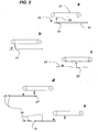
- the servo drill makes a first hole into the seal member; the seal is moved a predetermined amount; the first hole is then in position to receive a blind attachment; a blind attachment is then inserted through the first hole by the insertion device, and at the same time the servo drill is moved a predetermined amount and drills a second hole in the seal member; wherein this operation is repeated a plurality of times until the predetermined number of blind attachments are connected to the seal member.
- a system for inserting blind attachments into extruded seals comprising drilling members and insertion devices
- the improvement comprising an apparatus adapted to hold and move a seal member along a predetermined linear path; a linear drive servo drill; a drive belt rotationally attached to the apparatus and adapted to move the servo drill along a predetermined linear path parallel to the linear path of the seal member; such that the servo drill is used to drill a plurality of holes in the seal member at predetermined points along its length.
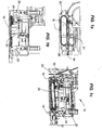
- the improved system for inserting blind attachments 10 is part of an existing blind attachment apparatus as is known in the art and as such, only the components specific to this invention are discussed in details.
- the improved system for inserting blind attachments 10 has an entry point 12 and an exit point 14 for the passage of a seal 16.
- the seal 16 enters by way of the entry point 12 and continues its guided course by being moved by a pair of servo pullers 18.
- a linear drive servo drill 20 running along a drive belt 21 makes a first hole 22 into the seal 16 and, as the seal 16 is moved, the first hole 22 is in position to have a blind attachment 24 inserted therethrough by way of an insertion tool 26, At the same time that the blind attachment 24 is inserted, a second hole 22 is made in the seal 16 by having the servo drill 20 moved at the appropriate location ,as per fig. 2b , for example.
- the servo drill 20 is a known device used in many fields and the insertion tool 26 is similar to those currently in use.
- the invention lies in the motion of the servo drill 20 running on a drive belt 21, in cooperation with the movement of the seal 16 along with the concurrent insertion of the blind attachment 24 by way of the insertion tool 26.
Landscapes
- Engineering & Computer Science (AREA)
- Mechanical Engineering (AREA)
- Control Of Cutting Processes (AREA)
- Perforating, Stamping-Out Or Severing By Means Other Than Cutting (AREA)
- Automatic Assembly (AREA)
Claims (8)
- Système pour l'insertion de fixations aveugles (24) comprenant :une paire de dispositifs d'entraînement asservi (18) adaptés pour maintenir et déplacer un élément d'étanchéité (16) le long d'une trajectoire linéaire prédéterminée ;une perceuse asservie (20) configurée se déplacer en coopération avec un déplacement de l'élément d'étanchéité, la perceuse asservie se déplaçant le long d'une trajectoire linéaire prédéterminée parallèle à ladite trajectoire linéaire prédéterminée dudit élément d'étanchéité (16), la perceuse asservie (20) étant configurée pour le forage d'une pluralité de trous (22, 22', 22", 22"') dans ledit élément d'étanchéité au niveau de points prédéterminés sur sa longueur ; etun dispositif d'insertion (26), séparé linéairement de la perceuse asservie (20) le long de la trajectoire linéaire prédéterminée, pour l'insertion d'une fixation aveugle (24) dans un parmi ladite pluralité de trous après que ledit élément d'étanchéité (16) soit déplacé d'une position de forage d'un parmi ladite pluralité de trous (22, 22', 22", 22'''), dans lequel, en même temps, lorsqu'une fixation aveugle (24) est insérée, un trou est réalisé dans l'élément d'étanchéité (16) en ayant déplacé la perceuse asservie (20) à l'emplacement approprié,caractérisé en ce que le dispositif d'insertion (26) est fixe.
- Système pour l'insertion de fixations aveugles (24) selon la revendication 1, comprenant une courroie d'entraînement (21) adaptée pour déplacer ladite perceuse asservie (20) le long de ladite trajectoire parallèle à ladite trajectoire linéaire prédéterminée dudit élément d'étanchéité (16).
- Système pour l'insertion de fixations aveugles (24) selon la revendication 2, dans lequel ledit dispositif d'insertion (26) est adapté pour insérer une pluralité de fixations aveugles (24) dans une pluralité desdits trous respectifs (22, 22', 22", 22''') successivement.
- Système pour l'insertion de fixations aveugles (24) selon la revendication 1, dans lequel :les deux extracteurs de la paire de dispositifs d'entraînement asservi (18) sont positionnés côte à côte le long de la trajectoire linéaire prédéterminée ; etla position de forage d'un parmi ladite pluralité de trous (22, 22', 22", 22''') et une position du dispositif d'insertion (26) sont toutes deux au sein d'une longueur des dispositifs d'entraînement asservi.
- Système pour l'insertion de fixations aveugles (24) selon la revendication 1, comprenant en outre :un organe de coupe d'entrée (28) situé au point d'entrée dudit système et adapté pour couper ledit élément d'étanchéité au niveau d'un emplacement souhaité ; etun organe de coupe de sortie (30) situé au point de sortie dudit système adapté pour couper ledit élément d'étanchéité au niveau d'un emplacement souhaité.
- Procédé pour l'insertion de fixations aveugles (24) à l'intérieur d'un élément d'étanchéité (16) comprenant :le maintien d'un élément d'étanchéité (16) entre une paire de dispositifs d'entraînement asservi (18) pour le déplacement de l'élément d'étanchéité (16) le long d'une trajectoire linéaire prédéterminée ;le forage d'une pluralité de trous (22, 22', 22", 22''') dans ledit élément d'étanchéité (16) au niveau de points prédéterminés sur sa longueur, le forage étant réalisé par une perceuse asservie (20) se déplaçant en coopération avec un mouvement de l'élément d'étanchéité (16), la perceuse asservie se déplaçant le long d'une trajectoire linéaire prédéterminée parallèle à ladite trajectoire linéaire prédéterminée dudit élément d'étanchéité (16) et ;l'insertion d'une fixation aveugle (24) dans un parmi ladite pluralité de trous (22, 22', 22", 22''') après que ledit élément d'étanchéité (16) soit déplacé d'une position de forage d'un parmi ladite pluralité de trous (22, 22', 22", 22"'), l'insertion étant réalisée par un dispositif d'insertion (26) séparé linéairement de la perceuse asservie (20) le long de la trajectoire linéaire prédéterminée ;caractérisé en ce qu'en même temps, lorsqu'une fixation aveugle (24) est insérée, un trou est réalisé dans l'élément d'étanchéité (16) en ayant déplacé la perceuse asservie (20) à l'emplacement approprié ;dans lequel le dispositif d'insertion (26) est fixe.
- Procédé pour l'insertion de fixations aveugles (24) selon la revendication 6, comprenant :le déplacement de ladite perceuse asservie (20) le long d'une trajectoire respective parallèle à ladite trajectoire linéaire prédéterminée dudit élément d'étanchéité (16) pour le forage de la pluralité de trous (22, 22', 22", 22''') dans ledit élément d'étanchéité au niveau de points prédéterminés sur sa longueur ;l'insertion d'une pluralité de fixations aveugles (24) dans une pluralité desdits trous respectifs (22, 22', 22", 22'") successivement.
- Procédé pour l'insertion de fixations aveugles (24) selon la revendication 7, comprenant :a) la réalisation d'un premier trou (22) dans ledit élément d'étanchéité (16) ;b) le déplacement dudit élément d'étanchéité (16) une quantité prédéterminée de sorte que ledit premier trou (22) se trouve alors en position pour recevoir une fixation aveugle (24) ; etc) l'insertion d'une fixation aveugle (24) à travers ledit premier trou (22) tandis que le déplacement de ladite perceuse asservie (20) une quantité prédéterminée pour le forage d'un deuxième trou (22') dans ledit élément d'étanchéité ;dans lequel les opérations a), b) et c) sont répétées une pluralité de fois jusqu'à ce qu'un nombre prédéterminé de fixations aveugles (24) soient connectés audit élément d'étanchéité (16).
Priority Applications (1)
| Application Number | Priority Date | Filing Date | Title |
|---|---|---|---|
| PL10782850T PL2467232T3 (pl) | 2009-06-05 | 2010-05-11 | Udoskonalony system do wkładania mocowań żaluzji |
Applications Claiming Priority (2)
| Application Number | Priority Date | Filing Date | Title |
|---|---|---|---|
| GBGB0909700.7A GB0909700D0 (en) | 2009-06-05 | 2009-06-05 | Improved system for inserting blind attachments |
| PCT/CA2010/000723 WO2010139046A1 (fr) | 2009-06-05 | 2010-05-11 | Système perfectionné pour introduction d'accessoires aveugles |
Publications (4)
| Publication Number | Publication Date |
|---|---|
| EP2467232A1 EP2467232A1 (fr) | 2012-06-27 |
| EP2467232A4 EP2467232A4 (fr) | 2013-07-03 |
| EP2467232B1 true EP2467232B1 (fr) | 2018-10-17 |
| EP2467232B8 EP2467232B8 (fr) | 2019-02-27 |
Family
ID=40936963
Family Applications (1)
| Application Number | Title | Priority Date | Filing Date |
|---|---|---|---|
| EP10782850.1A Active EP2467232B8 (fr) | 2009-06-05 | 2010-05-11 | Système perfectionné pour introduction d'accessoires aveugles |
Country Status (7)
| Country | Link |
|---|---|
| US (1) | US8528183B2 (fr) |
| EP (1) | EP2467232B8 (fr) |
| CA (1) | CA2701570C (fr) |
| ES (1) | ES2705679T3 (fr) |
| GB (1) | GB0909700D0 (fr) |
| PL (1) | PL2467232T3 (fr) |
| WO (1) | WO2010139046A1 (fr) |
Cited By (1)
| Publication number | Priority date | Publication date | Assignee | Title |
|---|---|---|---|---|
| CN108526892A (zh) * | 2018-04-09 | 2018-09-14 | 广东赛纳德智能装备有限公司 | 一种双动平衡加工设备 |
Families Citing this family (7)
| Publication number | Priority date | Publication date | Assignee | Title |
|---|---|---|---|---|
| US8951103B2 (en) * | 2010-10-27 | 2015-02-10 | Arzel Zoning Technology, Inc. | Foldable, boot loadable, insertable air damper device |
| US9266685B2 (en) | 2011-07-05 | 2016-02-23 | Conceptromec Inc. | Clip separating system, kit for assembling the same, and corresponding methods of operating and assembling associated thereof |
| CN102886545A (zh) * | 2012-10-24 | 2013-01-23 | 吴江华鹏制罐厂 | 一种多工件加工用钻床 |
| CN104907831A (zh) * | 2014-03-10 | 2015-09-16 | 苏州日邦自动化科技有限公司 | 一种组立熔接机 |
| CN104084799A (zh) * | 2014-07-06 | 2014-10-08 | 滁州开关电器科技有限公司 | 用于加工电力金具的钻孔攻牙机 |
| CN104097066A (zh) * | 2014-07-06 | 2014-10-15 | 滁州开关电器科技有限公司 | 电力金具用钻孔攻牙机 |
| CN114290060B (zh) * | 2021-12-31 | 2022-12-30 | 济南国宏建材有限公司 | 一种用于抗风降噪的百叶窗叶片加工装置 |
Family Cites Families (10)
| Publication number | Priority date | Publication date | Assignee | Title |
|---|---|---|---|---|
| US2972789A (en) | 1959-11-06 | 1961-02-28 | Gen Motors Corp | Sealing strip and method of manufacturing such strip |
| US3139674A (en) | 1961-06-22 | 1964-07-07 | Gen Motors Corp | Fastener assembly apparatus |
| US3199184A (en) | 1961-06-22 | 1965-08-10 | Gen Motors Corp | Elastomeric sealing strip and mounting means assembly procedure |
| JPS6071132A (ja) | 1983-09-29 | 1985-04-23 | Toyoda Gosei Co Ltd | ウェザ−ストリップの自動クリップ取付装置 |
| US4569116A (en) | 1984-03-12 | 1986-02-11 | Enterkin Manufacturing Co., Inc. | Automatic stud driving machine with pilot hole pre-drilling capability |
| JPS60232835A (ja) | 1984-04-30 | 1985-11-19 | Toyoda Gosei Co Ltd | ウエザ−ストリツプの自動クリツプ取付方法およびその装置 |
| JPH10281121A (ja) | 1997-04-03 | 1998-10-20 | Kinugawa Rubber Ind Co Ltd | クリップ帯体とその帯体を用いるクリップ取付方法及び装置 |
| US6143393A (en) * | 1997-12-16 | 2000-11-07 | Uni-Charm Corporation | Cleaning product and production process therefor |
| CA2424192C (fr) | 2002-04-05 | 2011-02-15 | John Howard Stewart | Percage et chevillage de joints d'etancheite de portes |
| US7171738B2 (en) * | 2003-10-09 | 2007-02-06 | Precision Automation, Inc. | Systems for processing workpieces |
-
2009
- 2009-06-05 GB GBGB0909700.7A patent/GB0909700D0/en not_active Ceased
-
2010
- 2010-04-29 CA CA2701570A patent/CA2701570C/fr active Active
- 2010-04-30 US US12/771,984 patent/US8528183B2/en active Active
- 2010-05-11 WO PCT/CA2010/000723 patent/WO2010139046A1/fr not_active Ceased
- 2010-05-11 ES ES10782850T patent/ES2705679T3/es active Active
- 2010-05-11 EP EP10782850.1A patent/EP2467232B8/fr active Active
- 2010-05-11 PL PL10782850T patent/PL2467232T3/pl unknown
Non-Patent Citations (1)
| Title |
|---|
| None * |
Cited By (1)
| Publication number | Priority date | Publication date | Assignee | Title |
|---|---|---|---|---|
| CN108526892A (zh) * | 2018-04-09 | 2018-09-14 | 广东赛纳德智能装备有限公司 | 一种双动平衡加工设备 |
Also Published As
| Publication number | Publication date |
|---|---|
| US20100306985A1 (en) | 2010-12-09 |
| EP2467232B8 (fr) | 2019-02-27 |
| CA2701570A1 (fr) | 2010-12-05 |
| PL2467232T3 (pl) | 2019-06-28 |
| ES2705679T3 (es) | 2019-03-26 |
| GB0909700D0 (en) | 2009-07-22 |
| CA2701570C (fr) | 2014-11-18 |
| WO2010139046A1 (fr) | 2010-12-09 |
| EP2467232A4 (fr) | 2013-07-03 |
| EP2467232A1 (fr) | 2012-06-27 |
| US8528183B2 (en) | 2013-09-10 |
Similar Documents
| Publication | Publication Date | Title |
|---|---|---|
| EP2467232B1 (fr) | Système perfectionné pour introduction d'accessoires aveugles | |
| CN102458757A (zh) | 用于供应连接元件的设备的单个化滑动件 | |
| US9333609B2 (en) | Tool carrier unit of a tool magazine | |
| EP3056311A1 (fr) | Support de profil | |
| JP4437445B2 (ja) | スライドファスナーの連続仕上装置 | |
| CN101844344B (zh) | 紧固件贮料条 | |
| JPS5911806A (ja) | 開離嵌挿具付スライドファスナに棒金具を取付ける装置 | |
| CN108746316B (zh) | 加工装置及生产设备 | |
| CN206901286U (zh) | 一种抓取砖胚的夹爪 | |
| US20160160526A1 (en) | Fencing assembly apparatus | |
| US10406660B2 (en) | Fastener driving system | |
| US10907707B2 (en) | Belt tensioning method | |
| CA2646448A1 (fr) | Procede permettant de reduire le retrecissement du diametre pres des extremites d'elements tubulaires dilates | |
| CN208961109U (zh) | 管体切割设备 | |
| EP2998064B1 (fr) | Dispositif de traitement | |
| KR200315306Y1 (ko) | 모헤어 조립장치 | |
| DE2507890A1 (de) | Verfahren und vorrichtung zur herstellung von leitern, insbesondere zur bearbeitung von holmen | |
| US8434204B2 (en) | Apparatus and method for trimming | |
| CN219788454U (zh) | 自动送管装置 | |
| CN218840655U (zh) | 一种磁块组装用侧推装置 | |
| CN213794402U (zh) | 一种铝型材打孔设备 | |
| CN110666478B (zh) | 夹持机构及具有其的电机定子插针机 | |
| CN214526668U (zh) | 定位组件及取料设备 | |
| CN208663193U (zh) | 管材治具 | |
| US11826966B2 (en) | Method and apparatus for inserting a reinforcing rod into a laminated material |
Legal Events
| Date | Code | Title | Description |
|---|---|---|---|
| PUAI | Public reference made under article 153(3) epc to a published international application that has entered the european phase |
Free format text: ORIGINAL CODE: 0009012 |
|
| 17P | Request for examination filed |
Effective date: 20120502 |
|
| AK | Designated contracting states |
Kind code of ref document: A1 Designated state(s): AL AT BE BG CH CY CZ DE DK EE ES FI FR GB GR HR HU IE IS IT LI LT LU LV MC MK MT NL NO PL PT RO SE SI SK SM TR |
|
| DAX | Request for extension of the european patent (deleted) | ||
| RAP1 | Party data changed (applicant data changed or rights of an application transferred) |
Owner name: MILAN CONCEPTION |
|
| RIN1 | Information on inventor provided before grant (corrected) |
Inventor name: MICHAUD, STEEVE Inventor name: LANGLOIS, BENOIT |
|
| A4 | Supplementary search report drawn up and despatched |
Effective date: 20130605 |
|
| RIC1 | Information provided on ipc code assigned before grant |
Ipc: B60J 10/00 20060101ALI20130530BHEP Ipc: B23P 19/04 20060101AFI20130530BHEP |
|
| STAA | Information on the status of an ep patent application or granted ep patent |
Free format text: STATUS: EXAMINATION IS IN PROGRESS |
|
| 17Q | First examination report despatched |
Effective date: 20161216 |
|
| GRAP | Despatch of communication of intention to grant a patent |
Free format text: ORIGINAL CODE: EPIDOSNIGR1 |
|
| STAA | Information on the status of an ep patent application or granted ep patent |
Free format text: STATUS: GRANT OF PATENT IS INTENDED |
|
| INTG | Intention to grant announced |
Effective date: 20180508 |
|
| GRAS | Grant fee paid |
Free format text: ORIGINAL CODE: EPIDOSNIGR3 |
|
| GRAA | (expected) grant |
Free format text: ORIGINAL CODE: 0009210 |
|
| STAA | Information on the status of an ep patent application or granted ep patent |
Free format text: STATUS: THE PATENT HAS BEEN GRANTED |
|
| AK | Designated contracting states |
Kind code of ref document: B1 Designated state(s): AL AT BE BG CH CY CZ DE DK EE ES FI FR GB GR HR HU IE IS IT LI LT LU LV MC MK MT NL NO PL PT RO SE SI SK SM TR |
|
| REG | Reference to a national code |
Ref country code: GB Ref legal event code: FG4D |
|
| REG | Reference to a national code |
Ref country code: CH Ref legal event code: EP |
|
| REG | Reference to a national code |
Ref country code: IE Ref legal event code: FG4D |
|
| REG | Reference to a national code |
Ref country code: DE Ref legal event code: R096 Ref document number: 602010054435 Country of ref document: DE Ref country code: AT Ref legal event code: REF Ref document number: 1053421 Country of ref document: AT Kind code of ref document: T Effective date: 20181115 |
|
| REG | Reference to a national code |
Ref country code: RO Ref legal event code: EPE |
|
| RAP2 | Party data changed (patent owner data changed or rights of a patent transferred) |
Owner name: MILAN CONCEPTION |
|
| REG | Reference to a national code |
Ref country code: CH Ref legal event code: PK Free format text: BERICHTIGUNG B8 |
|
| REG | Reference to a national code |
Ref country code: SE Ref legal event code: TRGR |
|
| REG | Reference to a national code |
Ref country code: NL Ref legal event code: MP Effective date: 20181017 |
|
| REG | Reference to a national code |
Ref country code: LT Ref legal event code: MG4D |
|
| REG | Reference to a national code |
Ref country code: AT Ref legal event code: MK05 Ref document number: 1053421 Country of ref document: AT Kind code of ref document: T Effective date: 20181017 |
|
| REG | Reference to a national code |
Ref country code: ES Ref legal event code: FG2A Ref document number: 2705679 Country of ref document: ES Kind code of ref document: T3 Effective date: 20190326 |
|
| PG25 | Lapsed in a contracting state [announced via postgrant information from national office to epo] |
Ref country code: NL Free format text: LAPSE BECAUSE OF FAILURE TO SUBMIT A TRANSLATION OF THE DESCRIPTION OR TO PAY THE FEE WITHIN THE PRESCRIBED TIME-LIMIT Effective date: 20181017 |
|
| PG25 | Lapsed in a contracting state [announced via postgrant information from national office to epo] |
Ref country code: FI Free format text: LAPSE BECAUSE OF FAILURE TO SUBMIT A TRANSLATION OF THE DESCRIPTION OR TO PAY THE FEE WITHIN THE PRESCRIBED TIME-LIMIT Effective date: 20181017 Ref country code: AT Free format text: LAPSE BECAUSE OF FAILURE TO SUBMIT A TRANSLATION OF THE DESCRIPTION OR TO PAY THE FEE WITHIN THE PRESCRIBED TIME-LIMIT Effective date: 20181017 Ref country code: LT Free format text: LAPSE BECAUSE OF FAILURE TO SUBMIT A TRANSLATION OF THE DESCRIPTION OR TO PAY THE FEE WITHIN THE PRESCRIBED TIME-LIMIT Effective date: 20181017 Ref country code: NO Free format text: LAPSE BECAUSE OF FAILURE TO SUBMIT A TRANSLATION OF THE DESCRIPTION OR TO PAY THE FEE WITHIN THE PRESCRIBED TIME-LIMIT Effective date: 20190117 Ref country code: HR Free format text: LAPSE BECAUSE OF FAILURE TO SUBMIT A TRANSLATION OF THE DESCRIPTION OR TO PAY THE FEE WITHIN THE PRESCRIBED TIME-LIMIT Effective date: 20181017 Ref country code: IS Free format text: LAPSE BECAUSE OF FAILURE TO SUBMIT A TRANSLATION OF THE DESCRIPTION OR TO PAY THE FEE WITHIN THE PRESCRIBED TIME-LIMIT Effective date: 20190217 Ref country code: LV Free format text: LAPSE BECAUSE OF FAILURE TO SUBMIT A TRANSLATION OF THE DESCRIPTION OR TO PAY THE FEE WITHIN THE PRESCRIBED TIME-LIMIT Effective date: 20181017 Ref country code: BG Free format text: LAPSE BECAUSE OF FAILURE TO SUBMIT A TRANSLATION OF THE DESCRIPTION OR TO PAY THE FEE WITHIN THE PRESCRIBED TIME-LIMIT Effective date: 20190117 |
|
| PG25 | Lapsed in a contracting state [announced via postgrant information from national office to epo] |
Ref country code: AL Free format text: LAPSE BECAUSE OF FAILURE TO SUBMIT A TRANSLATION OF THE DESCRIPTION OR TO PAY THE FEE WITHIN THE PRESCRIBED TIME-LIMIT Effective date: 20181017 Ref country code: PT Free format text: LAPSE BECAUSE OF FAILURE TO SUBMIT A TRANSLATION OF THE DESCRIPTION OR TO PAY THE FEE WITHIN THE PRESCRIBED TIME-LIMIT Effective date: 20190217 Ref country code: GR Free format text: LAPSE BECAUSE OF FAILURE TO SUBMIT A TRANSLATION OF THE DESCRIPTION OR TO PAY THE FEE WITHIN THE PRESCRIBED TIME-LIMIT Effective date: 20190118 |
|
| REG | Reference to a national code |
Ref country code: SK Ref legal event code: T3 Ref document number: E 29906 Country of ref document: SK |
|
| REG | Reference to a national code |
Ref country code: DE Ref legal event code: R097 Ref document number: 602010054435 Country of ref document: DE |
|
| PG25 | Lapsed in a contracting state [announced via postgrant information from national office to epo] |
Ref country code: DK Free format text: LAPSE BECAUSE OF FAILURE TO SUBMIT A TRANSLATION OF THE DESCRIPTION OR TO PAY THE FEE WITHIN THE PRESCRIBED TIME-LIMIT Effective date: 20181017 |
|
| PLBE | No opposition filed within time limit |
Free format text: ORIGINAL CODE: 0009261 |
|
| STAA | Information on the status of an ep patent application or granted ep patent |
Free format text: STATUS: NO OPPOSITION FILED WITHIN TIME LIMIT |
|
| PG25 | Lapsed in a contracting state [announced via postgrant information from national office to epo] |
Ref country code: SM Free format text: LAPSE BECAUSE OF FAILURE TO SUBMIT A TRANSLATION OF THE DESCRIPTION OR TO PAY THE FEE WITHIN THE PRESCRIBED TIME-LIMIT Effective date: 20181017 Ref country code: EE Free format text: LAPSE BECAUSE OF FAILURE TO SUBMIT A TRANSLATION OF THE DESCRIPTION OR TO PAY THE FEE WITHIN THE PRESCRIBED TIME-LIMIT Effective date: 20181017 |
|
| 26N | No opposition filed |
Effective date: 20190718 |
|
| PG25 | Lapsed in a contracting state [announced via postgrant information from national office to epo] |
Ref country code: SI Free format text: LAPSE BECAUSE OF FAILURE TO SUBMIT A TRANSLATION OF THE DESCRIPTION OR TO PAY THE FEE WITHIN THE PRESCRIBED TIME-LIMIT Effective date: 20181017 |
|
| REG | Reference to a national code |
Ref country code: CH Ref legal event code: PL |
|
| PG25 | Lapsed in a contracting state [announced via postgrant information from national office to epo] |
Ref country code: MC Free format text: LAPSE BECAUSE OF FAILURE TO SUBMIT A TRANSLATION OF THE DESCRIPTION OR TO PAY THE FEE WITHIN THE PRESCRIBED TIME-LIMIT Effective date: 20181017 Ref country code: CH Free format text: LAPSE BECAUSE OF NON-PAYMENT OF DUE FEES Effective date: 20190531 Ref country code: LI Free format text: LAPSE BECAUSE OF NON-PAYMENT OF DUE FEES Effective date: 20190531 |
|
| REG | Reference to a national code |
Ref country code: BE Ref legal event code: MM Effective date: 20190531 |
|
| PG25 | Lapsed in a contracting state [announced via postgrant information from national office to epo] |
Ref country code: LU Free format text: LAPSE BECAUSE OF NON-PAYMENT OF DUE FEES Effective date: 20190511 |
|
| PG25 | Lapsed in a contracting state [announced via postgrant information from national office to epo] |
Ref country code: TR Free format text: LAPSE BECAUSE OF FAILURE TO SUBMIT A TRANSLATION OF THE DESCRIPTION OR TO PAY THE FEE WITHIN THE PRESCRIBED TIME-LIMIT Effective date: 20181017 |
|
| PG25 | Lapsed in a contracting state [announced via postgrant information from national office to epo] |
Ref country code: IE Free format text: LAPSE BECAUSE OF NON-PAYMENT OF DUE FEES Effective date: 20190511 |
|
| PG25 | Lapsed in a contracting state [announced via postgrant information from national office to epo] |
Ref country code: BE Free format text: LAPSE BECAUSE OF NON-PAYMENT OF DUE FEES Effective date: 20190531 |
|
| PG25 | Lapsed in a contracting state [announced via postgrant information from national office to epo] |
Ref country code: CY Free format text: LAPSE BECAUSE OF FAILURE TO SUBMIT A TRANSLATION OF THE DESCRIPTION OR TO PAY THE FEE WITHIN THE PRESCRIBED TIME-LIMIT Effective date: 20181017 |
|
| PG25 | Lapsed in a contracting state [announced via postgrant information from national office to epo] |
Ref country code: MT Free format text: LAPSE BECAUSE OF FAILURE TO SUBMIT A TRANSLATION OF THE DESCRIPTION OR TO PAY THE FEE WITHIN THE PRESCRIBED TIME-LIMIT Effective date: 20181017 Ref country code: HU Free format text: LAPSE BECAUSE OF FAILURE TO SUBMIT A TRANSLATION OF THE DESCRIPTION OR TO PAY THE FEE WITHIN THE PRESCRIBED TIME-LIMIT; INVALID AB INITIO Effective date: 20100511 |
|
| PG25 | Lapsed in a contracting state [announced via postgrant information from national office to epo] |
Ref country code: MK Free format text: LAPSE BECAUSE OF FAILURE TO SUBMIT A TRANSLATION OF THE DESCRIPTION OR TO PAY THE FEE WITHIN THE PRESCRIBED TIME-LIMIT Effective date: 20181017 |
|
| P01 | Opt-out of the competence of the unified patent court (upc) registered |
Effective date: 20230512 |
|
| PGFP | Annual fee paid to national office [announced via postgrant information from national office to epo] |
Ref country code: PL Payment date: 20250408 Year of fee payment: 16 Ref country code: DE Payment date: 20250528 Year of fee payment: 16 |
|
| PGFP | Annual fee paid to national office [announced via postgrant information from national office to epo] |
Ref country code: GB Payment date: 20250520 Year of fee payment: 16 Ref country code: ES Payment date: 20250606 Year of fee payment: 16 |
|
| PGFP | Annual fee paid to national office [announced via postgrant information from national office to epo] |
Ref country code: IT Payment date: 20250522 Year of fee payment: 16 |
|
| PGFP | Annual fee paid to national office [announced via postgrant information from national office to epo] |
Ref country code: FR Payment date: 20250527 Year of fee payment: 16 |
|
| PGFP | Annual fee paid to national office [announced via postgrant information from national office to epo] |
Ref country code: RO Payment date: 20250429 Year of fee payment: 16 |
|
| PGFP | Annual fee paid to national office [announced via postgrant information from national office to epo] |
Ref country code: SK Payment date: 20250429 Year of fee payment: 16 |
|
| PGFP | Annual fee paid to national office [announced via postgrant information from national office to epo] |
Ref country code: CZ Payment date: 20250424 Year of fee payment: 16 |
|
| PGFP | Annual fee paid to national office [announced via postgrant information from national office to epo] |
Ref country code: SE Payment date: 20250526 Year of fee payment: 16 |