EP2467232B1 - Improved system for inserting blind attachments - Google Patents
Improved system for inserting blind attachments Download PDFInfo
- Publication number
- EP2467232B1 EP2467232B1 EP10782850.1A EP10782850A EP2467232B1 EP 2467232 B1 EP2467232 B1 EP 2467232B1 EP 10782850 A EP10782850 A EP 10782850A EP 2467232 B1 EP2467232 B1 EP 2467232B1
- Authority
- EP
- European Patent Office
- Prior art keywords
- seal member
- servo
- blind
- along
- holes
- Prior art date
- Legal status (The legal status is an assumption and is not a legal conclusion. Google has not performed a legal analysis and makes no representation as to the accuracy of the status listed.)
- Active
Links
Images
Classifications
-
- B—PERFORMING OPERATIONS; TRANSPORTING
- B23—MACHINE TOOLS; METAL-WORKING NOT OTHERWISE PROVIDED FOR
- B23P—METAL-WORKING NOT OTHERWISE PROVIDED FOR; COMBINED OPERATIONS; UNIVERSAL MACHINE TOOLS
- B23P19/00—Machines for simply fitting together or separating metal parts or objects, or metal and non-metal parts, whether or not involving some deformation; Tools or devices therefor so far as not provided for in other classes
- B23P19/04—Machines for simply fitting together or separating metal parts or objects, or metal and non-metal parts, whether or not involving some deformation; Tools or devices therefor so far as not provided for in other classes for assembling or disassembling parts
-
- Y—GENERAL TAGGING OF NEW TECHNOLOGICAL DEVELOPMENTS; GENERAL TAGGING OF CROSS-SECTIONAL TECHNOLOGIES SPANNING OVER SEVERAL SECTIONS OF THE IPC; TECHNICAL SUBJECTS COVERED BY FORMER USPC CROSS-REFERENCE ART COLLECTIONS [XRACs] AND DIGESTS
- Y10—TECHNICAL SUBJECTS COVERED BY FORMER USPC
- Y10T—TECHNICAL SUBJECTS COVERED BY FORMER US CLASSIFICATION
- Y10T29/00—Metal working
- Y10T29/49—Method of mechanical manufacture
- Y10T29/49826—Assembling or joining
- Y10T29/49863—Assembling or joining with prestressing of part
- Y10T29/4987—Elastic joining of parts
- Y10T29/49872—Confining elastic part in socket
-
- Y—GENERAL TAGGING OF NEW TECHNOLOGICAL DEVELOPMENTS; GENERAL TAGGING OF CROSS-SECTIONAL TECHNOLOGIES SPANNING OVER SEVERAL SECTIONS OF THE IPC; TECHNICAL SUBJECTS COVERED BY FORMER USPC CROSS-REFERENCE ART COLLECTIONS [XRACs] AND DIGESTS
- Y10—TECHNICAL SUBJECTS COVERED BY FORMER USPC
- Y10T—TECHNICAL SUBJECTS COVERED BY FORMER US CLASSIFICATION
- Y10T29/00—Metal working
- Y10T29/51—Plural diverse manufacturing apparatus including means for metal shaping or assembling
-
- Y—GENERAL TAGGING OF NEW TECHNOLOGICAL DEVELOPMENTS; GENERAL TAGGING OF CROSS-SECTIONAL TECHNOLOGIES SPANNING OVER SEVERAL SECTIONS OF THE IPC; TECHNICAL SUBJECTS COVERED BY FORMER USPC CROSS-REFERENCE ART COLLECTIONS [XRACs] AND DIGESTS
- Y10—TECHNICAL SUBJECTS COVERED BY FORMER USPC
- Y10T—TECHNICAL SUBJECTS COVERED BY FORMER US CLASSIFICATION
- Y10T408/00—Cutting by use of rotating axially moving tool
- Y10T408/52—Cutting by use of rotating axially moving tool with work advancing or guiding means
-
- Y—GENERAL TAGGING OF NEW TECHNOLOGICAL DEVELOPMENTS; GENERAL TAGGING OF CROSS-SECTIONAL TECHNOLOGIES SPANNING OVER SEVERAL SECTIONS OF THE IPC; TECHNICAL SUBJECTS COVERED BY FORMER USPC CROSS-REFERENCE ART COLLECTIONS [XRACs] AND DIGESTS
- Y10—TECHNICAL SUBJECTS COVERED BY FORMER USPC
- Y10T—TECHNICAL SUBJECTS COVERED BY FORMER US CLASSIFICATION
- Y10T408/00—Cutting by use of rotating axially moving tool
- Y10T408/83—Tool-support with means to move Tool relative to tool-support
Definitions
- the present invention relates generally to manufacturing methods but more particularly to the insertion of blind attachments into extruded seals.
- US 2003/0188425 A1 discloses that the combination of hole forming and pinning assembly and camera and guide bed and rubber strip base move along the direction of the length of the rubber strip to move the hole forming and pinning assembly and camera to the next desired location along the length of the rubber strip.
- US 3,199,184 discloses that the sealing strip could be moved at a continuous rate and that the drilling and inserting mechanisms could be moved therewith in predetermined locations for a predetermined length of time during the drilling as well as the inserting operation occur.
- JP 10-281 121 discloses a system for facilitating handling and storage of clip strip substances.
- the present invention which will be described subsequently in greater detail, is to provide objects and advantages which are: To provide for a way of combining two operations, that of drilling the next hole while the blind attachment is inserted in the previously drilled hole.
- the present invention generally comprises an apparatus adapted to hold and move a seal member along a predetermined linear path; a linear drive servo drill; a drive belt rotationally attached to the apparatus and adapted to move the servo drill along a predetermined linear path parallel to the linear path of the seal member; such that the servo drill is used to drill a plurality of holes in the seal member at predetermined points along its length.
- the linear motion of the servo drill is adapted to be in cooperation with the linear motion of the seal member.
- An insertion device is mechanically attached to the apparatus and adapted to insert a blind attachment within one of the plurality of holes after the seal member is moved from the position wherein the one of the plurality of holes was formed by the servo drill.
- the insertion device is adapted to insert a plurality of blind attachments respectively into a plurality of the holes in succession as the servo drill and the seal member move linearly respectively at the same time.
- a pair of servo pullers mechanically attached to the apparatus and adapted to move the seal member along its linear path.
- an entry cutter attached to the apparatus and located at an entry point where the seal member is adapted to enter the apparatus, and adapted to cut the seal member at a desired location; and an exit cutter attached to the apparatus and located at an exit point where the seal member is adapted to exit the apparatus, and adapted to cut the seal member at a desired location.
- a method for inserting blind attachments within a seal member comprising the features of claim 6 is provided.
- the seal member enters the apparatus is moved linearly along its respective path; the servo drill moves along its respective path drilling a plurality of holes in the seal member at predetermined points along its length; wherein the insertion device inserts a plurality of blind attachments respectively into a plurality of the holes in succession as the servo drill and the seal member move linearly respectively at the same time; wherein the entry cutter cuts the seal member at a predetermined length; and wherein the exit cutter cuts the seal member when the desired length of the seal member is achieved and reaches the exit cutter.
- the servo drill makes a first hole into the seal member; the seal is moved a predetermined amount; the first hole is then in position to receive a blind attachment; a blind attachment is then inserted through the first hole by the insertion device, and at the same time the servo drill is moved a predetermined amount and drills a second hole in the seal member; wherein this operation is repeated a plurality of times until the predetermined number of blind attachments are connected to the seal member.
- a system for inserting blind attachments into extruded seals comprising drilling members and insertion devices
- the improvement comprising an apparatus adapted to hold and move a seal member along a predetermined linear path; a linear drive servo drill; a drive belt rotationally attached to the apparatus and adapted to move the servo drill along a predetermined linear path parallel to the linear path of the seal member; such that the servo drill is used to drill a plurality of holes in the seal member at predetermined points along its length.
- the improved system for inserting blind attachments 10 is part of an existing blind attachment apparatus as is known in the art and as such, only the components specific to this invention are discussed in details.
- the improved system for inserting blind attachments 10 has an entry point 12 and an exit point 14 for the passage of a seal 16.
- the seal 16 enters by way of the entry point 12 and continues its guided course by being moved by a pair of servo pullers 18.
- a linear drive servo drill 20 running along a drive belt 21 makes a first hole 22 into the seal 16 and, as the seal 16 is moved, the first hole 22 is in position to have a blind attachment 24 inserted therethrough by way of an insertion tool 26, At the same time that the blind attachment 24 is inserted, a second hole 22 is made in the seal 16 by having the servo drill 20 moved at the appropriate location ,as per fig. 2b , for example.
- the servo drill 20 is a known device used in many fields and the insertion tool 26 is similar to those currently in use.
- the invention lies in the motion of the servo drill 20 running on a drive belt 21, in cooperation with the movement of the seal 16 along with the concurrent insertion of the blind attachment 24 by way of the insertion tool 26.
Landscapes
- Engineering & Computer Science (AREA)
- Mechanical Engineering (AREA)
- Control Of Cutting Processes (AREA)
- Perforating, Stamping-Out Or Severing By Means Other Than Cutting (AREA)
- Automatic Assembly (AREA)
Description
- The present invention relates generally to manufacturing methods but more particularly to the insertion of blind attachments into extruded seals.
- In various industries, such as the car industry, for example, there is a need for rubber seals made using an extrusion process. After being extruded, the seals sometimes need an attachment means which will attach the seal to a door, for example. The current methods are quite slow because a hole is first drilled and then the attachment means is installed and the two operations are not done simultaneously.
-
US 2003/0188425 A1 discloses that the combination of hole forming and pinning assembly and camera and guide bed and rubber strip base move along the direction of the length of the rubber strip to move the hole forming and pinning assembly and camera to the next desired location along the length of the rubber strip. By moving the guide bed and assembly and camera, which are thus all operating as movement fixtures, the time between succeeding forming and pinning steps can be shortened. -
US 3,199,184 discloses that the sealing strip could be moved at a continuous rate and that the drilling and inserting mechanisms could be moved therewith in predetermined locations for a predetermined length of time during the drilling as well as the inserting operation occur. -
JP 10-281 121 - The object of the invention is solved by a system according to claim 1 and a method according to claim 6. Preferred embodiments are presented in the dependent claims.
- In view of the foregoing disadvantages inherent in the known devices now present in the prior art, the present invention, which will be described subsequently in greater detail, is to provide objects and advantages which are:
To provide for a way of combining two operations, that of drilling the next hole while the blind attachment is inserted in the previously drilled hole. - To attain these ends, the present invention generally comprises an apparatus adapted to hold and move a seal member along a predetermined linear path; a linear drive servo drill; a drive belt rotationally attached to the apparatus and adapted to move the servo drill along a predetermined linear path parallel to the linear path of the seal member; such that the servo drill is used to drill a plurality of holes in the seal member at predetermined points along its length.
- The linear motion of the servo drill is adapted to be in cooperation with the linear motion of the seal member.
- An insertion device is mechanically attached to the apparatus and adapted to insert a blind attachment within one of the plurality of holes after the seal member is moved from the position wherein the one of the plurality of holes was formed by the servo drill.
- The insertion device is adapted to insert a plurality of blind attachments respectively into a plurality of the holes in succession as the servo drill and the seal member move linearly respectively at the same time.
- A pair of servo pullers mechanically attached to the apparatus and adapted to move the seal member along its linear path.
- Preferably an entry cutter attached to the apparatus and located at an entry point where the seal member is adapted to enter the apparatus, and adapted to cut the seal member at a desired location; and an exit cutter attached to the apparatus and located at an exit point where the seal member is adapted to exit the apparatus, and adapted to cut the seal member at a desired location.
- A method for inserting blind attachments within a seal member comprising the features of claim 6 is provided.
- Preferably according to the method for inserting blind attachments the seal member enters the apparatus, is moved linearly along its respective path; the servo drill moves along its respective path drilling a plurality of holes in the seal member at predetermined points along its length; wherein the insertion device inserts a plurality of blind attachments respectively into a plurality of the holes in succession as the servo drill and the seal member move linearly respectively at the same time; wherein the entry cutter cuts the seal member at a predetermined length; and wherein the exit cutter cuts the seal member when the desired length of the seal member is achieved and reaches the exit cutter.
- The servo drill makes a first hole into the seal member; the seal is moved a predetermined amount; the first hole is then in position to receive a blind attachment; a blind attachment is then inserted through the first hole by the insertion device, and at the same time the servo drill is moved a predetermined amount and drills a second hole in the seal member; wherein this operation is repeated a plurality of times until the predetermined number of blind attachments are connected to the seal member.
- In a system for inserting blind attachments into extruded seals comprising drilling members and insertion devices, the improvement comprising an apparatus adapted to hold and move a seal member along a predetermined linear path; a linear drive servo drill; a drive belt rotationally attached to the apparatus and adapted to move the servo drill along a predetermined linear path parallel to the linear path of the seal member; such that the servo drill is used to drill a plurality of holes in the seal member at predetermined points along its length.
- For a better understanding of the invention, its operating advantages and the specific objects attained by its uses, reference should be made to the accompanying drawings and descriptive matter which contains illustrated preferred embodiments of the invention.
-
-
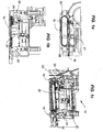
Figs. 1a -c top, front and isometric views, respectively, of the invention. -
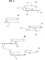
Figs. 2a -e Diagram views of the sequence of operations. - An improved system for inserting
blind attachments 10 is part of an existing blind attachment apparatus as is known in the art and as such, only the components specific to this invention are discussed in details. The improved system for insertingblind attachments 10 has an entry point 12 and anexit point 14 for the passage of aseal 16. Theseal 16 enters by way of the entry point 12 and continues its guided course by being moved by a pair ofservo pullers 18. - As shown in the series of figures from 2a to 2e, inclusively, a linear
drive servo drill 20 running along adrive belt 21 makes afirst hole 22 into theseal 16 and, as theseal 16 is moved, thefirst hole 22 is in position to have ablind attachment 24 inserted therethrough by way of aninsertion tool 26, At the same time that theblind attachment 24 is inserted, asecond hole 22 is made in theseal 16 by having theservo drill 20 moved at the appropriate location ,as perfig. 2b , for example. The other figures of thefigs. 2a-e sequence show that theseal 16 and theservo drill 20 both move at the same time, which forces theservo drill 20 to adjust so as to drillholes seal 16 positions itself under the blindattachment insertion device 26 which is itself stationary. An entry and anexit cutter seal 16 to length. - The
servo drill 20 is a known device used in many fields and theinsertion tool 26 is similar to those currently in use. - The invention lies in the motion of the
servo drill 20 running on adrive belt 21, in cooperation with the movement of theseal 16 along with the concurrent insertion of theblind attachment 24 by way of theinsertion tool 26. - As to a further discussion of the manner of usage and operation of the present invention, the same should be apparent from the above description. Accordingly, no further discussion relating to the manner of usage and operation will be provided.
- Therefore, the foregoing is considered as illustrative only of the principles of the invention. Further, since numerous modifications and changes will readily occur to those skilled in the art, it is not desired to limit the invention to the exact construction and operation shown and described, and accordingly, all suitable modifications and equivalents may be resorted to, falling within the scope of the invention, as defined in the claims.
Claims (8)
- A system for inserting blind attachments (24) comprising:a pair of servo pullers (18) adapted to hold and move a seal member (16) along a predetermined linear path;a servo drill (20) configured for moving in cooperation with a movement of the seal member, the servo drill moving along a predetermined linear path parallel to said predetermined linear path of said seal member (16), the servo drill (20) being configured for drilling a plurality of holes (22, 22', 22", 22''') in said seal member at predetermined points along its length; andan insertion device (26), linearly separated from the servo drill (20) along the predetermined linear path, for inserting a blind attachment (24) within one of said plurality of holes after said seal member (16) is moved from a drilling position of one of said plurality of holes (22, 22', 22", 22'"), wherein concurrently as a blind attachment (24) is inserted a hole is made in the seal member (16) by having the servo drill (20) moved at the appropriate location,characterized in that the insertion device (26) is stationary.
- The system for inserting blind attachments (24) of claim 1, comprising a drive belt (21) adapted to move said servo drill (20) along said path parallel to said predetermined linear path of said seal member (16).
- The system for inserting blind attachments (24) of claim 2, wherein said insertion device (26) is adapted to insert a plurality of blind attachments (24) into a plurality of respective said holes (22, 22', 22", 22'") in succession.
- The system for inserting blind attachments (24) of claim 1, wherein:the two pullers of the pair of servo pullers (18) are positioned side by side along the predetermined linear path; andthe drilling position of one of said plurality of holes (22, 22', 22", 22''') and a position of the insertion device (26) are both within a length of the servo pullers.
- The system for inserting blind attachments (24) of claim 1, further comprising:an entry cutter (28) located at an entry point of said system and adapted to cut said seal member at a desired location; andan exit cutter (30) located at an exit point and of said system adapted to cut said seal member at a desired location.
- A method for inserting blind attachments (24) within a seal member (16) comprising:holding a seal member (16) between a pair of servo pullers (18) for moving the seal member (16) along a predetermined linear path;drilling a plurality of holes (22, 22', 22", 22''') in said seal member (16) at predetermined points along its length, the drilling being effected by a servo drill (20) moving in cooperation with a movement of the seal member (16), the servo drill moving along a predetermined linear path parallel to said predetermined linear path of said seal member (16) and;inserting a blind attachment (24) within one of said plurality of holes (22, 22', 22", 22'") after said seal member (16) is moved from a drilling position of one of said plurality of holes (22, 22', 22", 22'"), the insertion being effected by an insertion device (26) linearly separated from the servo drill (20) along the predetermined linear path;characterized in that concurrently as a blind attachment (24) is inserted a hole is made in the seal member (16) by having the servo drill (20) moved at the appropriate location;wherein the insertion device (26) is stationary.
- The method for inserting blind attachments (24) of claim 6, comprising:moving said servo drill (20) along a respective path parallel to said predetermined linear path of said seal member (16) for drilling the plurality of holes (22, 22', 22", 22''') in said seal member at predetermined points along its length;inserting a plurality of blind attachments (24) into a plurality of respective of said holes (22, 22', 22", 22''') in succession.
- The method for inserting blind attachments (24) of claim 7, comprising:a) making a first hole (22) into said seal member (16);b) moving said seal member (16) a predetermined amount so that said first hole (22) is then in position to receive a blind attachment (24); andc) inserting a blind attachment (24) through said first hole (22) while moving said servo drill (20) a predetermined amount for drilling a second hole (22') in said seal member;wherein operations a), b) and c) are repeated a plurality of times until a predetermined number of blind attachments (24) are connected to said seal member (16).
Priority Applications (1)
| Application Number | Priority Date | Filing Date | Title |
|---|---|---|---|
| PL10782850T PL2467232T3 (en) | 2009-06-05 | 2010-05-11 | Improved system for inserting blind attachments |
Applications Claiming Priority (2)
| Application Number | Priority Date | Filing Date | Title |
|---|---|---|---|
| GBGB0909700.7A GB0909700D0 (en) | 2009-06-05 | 2009-06-05 | Improved system for inserting blind attachments |
| PCT/CA2010/000723 WO2010139046A1 (en) | 2009-06-05 | 2010-05-11 | Improved system for inserting blind attachments |
Publications (4)
| Publication Number | Publication Date |
|---|---|
| EP2467232A1 EP2467232A1 (en) | 2012-06-27 |
| EP2467232A4 EP2467232A4 (en) | 2013-07-03 |
| EP2467232B1 true EP2467232B1 (en) | 2018-10-17 |
| EP2467232B8 EP2467232B8 (en) | 2019-02-27 |
Family
ID=40936963
Family Applications (1)
| Application Number | Title | Priority Date | Filing Date |
|---|---|---|---|
| EP10782850.1A Active EP2467232B8 (en) | 2009-06-05 | 2010-05-11 | Improved system for inserting blind attachments |
Country Status (7)
| Country | Link |
|---|---|
| US (1) | US8528183B2 (en) |
| EP (1) | EP2467232B8 (en) |
| CA (1) | CA2701570C (en) |
| ES (1) | ES2705679T3 (en) |
| GB (1) | GB0909700D0 (en) |
| PL (1) | PL2467232T3 (en) |
| WO (1) | WO2010139046A1 (en) |
Cited By (1)
| Publication number | Priority date | Publication date | Assignee | Title |
|---|---|---|---|---|
| CN108526892A (en) * | 2018-04-09 | 2018-09-14 | 广东赛纳德智能装备有限公司 | A kind of double acting balance process equipment |
Families Citing this family (7)
| Publication number | Priority date | Publication date | Assignee | Title |
|---|---|---|---|---|
| US8951103B2 (en) * | 2010-10-27 | 2015-02-10 | Arzel Zoning Technology, Inc. | Foldable, boot loadable, insertable air damper device |
| US9266685B2 (en) | 2011-07-05 | 2016-02-23 | Conceptromec Inc. | Clip separating system, kit for assembling the same, and corresponding methods of operating and assembling associated thereof |
| CN102886545A (en) * | 2012-10-24 | 2013-01-23 | 吴江华鹏制罐厂 | Drilling machine for machining multiple workpieces |
| CN104907831A (en) * | 2014-03-10 | 2015-09-16 | 苏州日邦自动化科技有限公司 | Assemblage welding machine |
| CN104084799A (en) * | 2014-07-06 | 2014-10-08 | 滁州开关电器科技有限公司 | Drilling and tapping machine for machining electric power fittings |
| CN104097066A (en) * | 2014-07-06 | 2014-10-15 | 滁州开关电器科技有限公司 | Drilling and tapping machine for electric power fittings |
| CN114290060B (en) * | 2021-12-31 | 2022-12-30 | 济南国宏建材有限公司 | A shutter blade processingequipment for wind-resistant falls and make an uproar |
Family Cites Families (10)
| Publication number | Priority date | Publication date | Assignee | Title |
|---|---|---|---|---|
| US2972789A (en) | 1959-11-06 | 1961-02-28 | Gen Motors Corp | Sealing strip and method of manufacturing such strip |
| US3139674A (en) | 1961-06-22 | 1964-07-07 | Gen Motors Corp | Fastener assembly apparatus |
| US3199184A (en) | 1961-06-22 | 1965-08-10 | Gen Motors Corp | Elastomeric sealing strip and mounting means assembly procedure |
| JPS6071132A (en) | 1983-09-29 | 1985-04-23 | Toyoda Gosei Co Ltd | Automatic clip-fitting device of weather strip |
| US4569116A (en) | 1984-03-12 | 1986-02-11 | Enterkin Manufacturing Co., Inc. | Automatic stud driving machine with pilot hole pre-drilling capability |
| JPS60232835A (en) | 1984-04-30 | 1985-11-19 | Toyoda Gosei Co Ltd | Automatically installing method and device of clip for weather strip |
| JPH10281121A (en) | 1997-04-03 | 1998-10-20 | Kinugawa Rubber Ind Co Ltd | Clip strip substance and method and device for mounting clip using the strip substance |
| US6143393A (en) * | 1997-12-16 | 2000-11-07 | Uni-Charm Corporation | Cleaning product and production process therefor |
| CA2424192C (en) | 2002-04-05 | 2011-02-15 | John Howard Stewart | Door seal drilling and pinning |
| US7171738B2 (en) * | 2003-10-09 | 2007-02-06 | Precision Automation, Inc. | Systems for processing workpieces |
-
2009
- 2009-06-05 GB GBGB0909700.7A patent/GB0909700D0/en not_active Ceased
-
2010
- 2010-04-29 CA CA2701570A patent/CA2701570C/en active Active
- 2010-04-30 US US12/771,984 patent/US8528183B2/en active Active
- 2010-05-11 WO PCT/CA2010/000723 patent/WO2010139046A1/en not_active Ceased
- 2010-05-11 ES ES10782850T patent/ES2705679T3/en active Active
- 2010-05-11 EP EP10782850.1A patent/EP2467232B8/en active Active
- 2010-05-11 PL PL10782850T patent/PL2467232T3/en unknown
Non-Patent Citations (1)
| Title |
|---|
| None * |
Cited By (1)
| Publication number | Priority date | Publication date | Assignee | Title |
|---|---|---|---|---|
| CN108526892A (en) * | 2018-04-09 | 2018-09-14 | 广东赛纳德智能装备有限公司 | A kind of double acting balance process equipment |
Also Published As
| Publication number | Publication date |
|---|---|
| US20100306985A1 (en) | 2010-12-09 |
| EP2467232B8 (en) | 2019-02-27 |
| CA2701570A1 (en) | 2010-12-05 |
| PL2467232T3 (en) | 2019-06-28 |
| ES2705679T3 (en) | 2019-03-26 |
| GB0909700D0 (en) | 2009-07-22 |
| CA2701570C (en) | 2014-11-18 |
| WO2010139046A1 (en) | 2010-12-09 |
| EP2467232A4 (en) | 2013-07-03 |
| EP2467232A1 (en) | 2012-06-27 |
| US8528183B2 (en) | 2013-09-10 |
Similar Documents
| Publication | Publication Date | Title |
|---|---|---|
| EP2467232B1 (en) | Improved system for inserting blind attachments | |
| CN102458757A (en) | Singulation slide for an apparatus for feeding a connecting element | |
| US9333609B2 (en) | Tool carrier unit of a tool magazine | |
| EP3056311A1 (en) | Profile holder | |
| JP4437445B2 (en) | Slide fastener continuous finishing device | |
| CN101844344B (en) | Fastening element magazine strip | |
| JPS5911806A (en) | Method and apparatus for attaching rod metal fittings to slide fastener with openable inlay and insert tool | |
| CN108746316B (en) | Processing device and production equipment | |
| CN206901286U (en) | A kind of clamping jaw for capturing adobe | |
| US20160160526A1 (en) | Fencing assembly apparatus | |
| US10406660B2 (en) | Fastener driving system | |
| US10907707B2 (en) | Belt tensioning method | |
| CA2646448A1 (en) | Method for reducing diameter reduction near ends of expanded tubulars | |
| CN208961109U (en) | Tube body cutting equipment | |
| EP2998064B1 (en) | Processing device | |
| KR200315306Y1 (en) | Assembling device of mohair | |
| DE2507890A1 (en) | Sensor-actuated ladder production process - has stringer moved in clamps and miller and hole cutter operating for successive rungs | |
| US8434204B2 (en) | Apparatus and method for trimming | |
| CN219788454U (en) | Automatic pipe feeding device | |
| CN218840655U (en) | Side pushing device for assembling magnetic blocks | |
| CN213794402U (en) | Aluminium alloy drilling equipment | |
| CN110666478B (en) | Clamping mechanism and motor stator pin inserting machine with same | |
| CN214526668U (en) | Positioning assembly and material taking equipment | |
| CN208663193U (en) | Tubing jig | |
| US11826966B2 (en) | Method and apparatus for inserting a reinforcing rod into a laminated material |
Legal Events
| Date | Code | Title | Description |
|---|---|---|---|
| PUAI | Public reference made under article 153(3) epc to a published international application that has entered the european phase |
Free format text: ORIGINAL CODE: 0009012 |
|
| 17P | Request for examination filed |
Effective date: 20120502 |
|
| AK | Designated contracting states |
Kind code of ref document: A1 Designated state(s): AL AT BE BG CH CY CZ DE DK EE ES FI FR GB GR HR HU IE IS IT LI LT LU LV MC MK MT NL NO PL PT RO SE SI SK SM TR |
|
| DAX | Request for extension of the european patent (deleted) | ||
| RAP1 | Party data changed (applicant data changed or rights of an application transferred) |
Owner name: MILAN CONCEPTION |
|
| RIN1 | Information on inventor provided before grant (corrected) |
Inventor name: MICHAUD, STEEVE Inventor name: LANGLOIS, BENOIT |
|
| A4 | Supplementary search report drawn up and despatched |
Effective date: 20130605 |
|
| RIC1 | Information provided on ipc code assigned before grant |
Ipc: B60J 10/00 20060101ALI20130530BHEP Ipc: B23P 19/04 20060101AFI20130530BHEP |
|
| STAA | Information on the status of an ep patent application or granted ep patent |
Free format text: STATUS: EXAMINATION IS IN PROGRESS |
|
| 17Q | First examination report despatched |
Effective date: 20161216 |
|
| GRAP | Despatch of communication of intention to grant a patent |
Free format text: ORIGINAL CODE: EPIDOSNIGR1 |
|
| STAA | Information on the status of an ep patent application or granted ep patent |
Free format text: STATUS: GRANT OF PATENT IS INTENDED |
|
| INTG | Intention to grant announced |
Effective date: 20180508 |
|
| GRAS | Grant fee paid |
Free format text: ORIGINAL CODE: EPIDOSNIGR3 |
|
| GRAA | (expected) grant |
Free format text: ORIGINAL CODE: 0009210 |
|
| STAA | Information on the status of an ep patent application or granted ep patent |
Free format text: STATUS: THE PATENT HAS BEEN GRANTED |
|
| AK | Designated contracting states |
Kind code of ref document: B1 Designated state(s): AL AT BE BG CH CY CZ DE DK EE ES FI FR GB GR HR HU IE IS IT LI LT LU LV MC MK MT NL NO PL PT RO SE SI SK SM TR |
|
| REG | Reference to a national code |
Ref country code: GB Ref legal event code: FG4D |
|
| REG | Reference to a national code |
Ref country code: CH Ref legal event code: EP |
|
| REG | Reference to a national code |
Ref country code: IE Ref legal event code: FG4D |
|
| REG | Reference to a national code |
Ref country code: DE Ref legal event code: R096 Ref document number: 602010054435 Country of ref document: DE Ref country code: AT Ref legal event code: REF Ref document number: 1053421 Country of ref document: AT Kind code of ref document: T Effective date: 20181115 |
|
| REG | Reference to a national code |
Ref country code: RO Ref legal event code: EPE |
|
| RAP2 | Party data changed (patent owner data changed or rights of a patent transferred) |
Owner name: MILAN CONCEPTION |
|
| REG | Reference to a national code |
Ref country code: CH Ref legal event code: PK Free format text: BERICHTIGUNG B8 |
|
| REG | Reference to a national code |
Ref country code: SE Ref legal event code: TRGR |
|
| REG | Reference to a national code |
Ref country code: NL Ref legal event code: MP Effective date: 20181017 |
|
| REG | Reference to a national code |
Ref country code: LT Ref legal event code: MG4D |
|
| REG | Reference to a national code |
Ref country code: AT Ref legal event code: MK05 Ref document number: 1053421 Country of ref document: AT Kind code of ref document: T Effective date: 20181017 |
|
| REG | Reference to a national code |
Ref country code: ES Ref legal event code: FG2A Ref document number: 2705679 Country of ref document: ES Kind code of ref document: T3 Effective date: 20190326 |
|
| PG25 | Lapsed in a contracting state [announced via postgrant information from national office to epo] |
Ref country code: NL Free format text: LAPSE BECAUSE OF FAILURE TO SUBMIT A TRANSLATION OF THE DESCRIPTION OR TO PAY THE FEE WITHIN THE PRESCRIBED TIME-LIMIT Effective date: 20181017 |
|
| PG25 | Lapsed in a contracting state [announced via postgrant information from national office to epo] |
Ref country code: FI Free format text: LAPSE BECAUSE OF FAILURE TO SUBMIT A TRANSLATION OF THE DESCRIPTION OR TO PAY THE FEE WITHIN THE PRESCRIBED TIME-LIMIT Effective date: 20181017 Ref country code: AT Free format text: LAPSE BECAUSE OF FAILURE TO SUBMIT A TRANSLATION OF THE DESCRIPTION OR TO PAY THE FEE WITHIN THE PRESCRIBED TIME-LIMIT Effective date: 20181017 Ref country code: LT Free format text: LAPSE BECAUSE OF FAILURE TO SUBMIT A TRANSLATION OF THE DESCRIPTION OR TO PAY THE FEE WITHIN THE PRESCRIBED TIME-LIMIT Effective date: 20181017 Ref country code: NO Free format text: LAPSE BECAUSE OF FAILURE TO SUBMIT A TRANSLATION OF THE DESCRIPTION OR TO PAY THE FEE WITHIN THE PRESCRIBED TIME-LIMIT Effective date: 20190117 Ref country code: HR Free format text: LAPSE BECAUSE OF FAILURE TO SUBMIT A TRANSLATION OF THE DESCRIPTION OR TO PAY THE FEE WITHIN THE PRESCRIBED TIME-LIMIT Effective date: 20181017 Ref country code: IS Free format text: LAPSE BECAUSE OF FAILURE TO SUBMIT A TRANSLATION OF THE DESCRIPTION OR TO PAY THE FEE WITHIN THE PRESCRIBED TIME-LIMIT Effective date: 20190217 Ref country code: LV Free format text: LAPSE BECAUSE OF FAILURE TO SUBMIT A TRANSLATION OF THE DESCRIPTION OR TO PAY THE FEE WITHIN THE PRESCRIBED TIME-LIMIT Effective date: 20181017 Ref country code: BG Free format text: LAPSE BECAUSE OF FAILURE TO SUBMIT A TRANSLATION OF THE DESCRIPTION OR TO PAY THE FEE WITHIN THE PRESCRIBED TIME-LIMIT Effective date: 20190117 |
|
| PG25 | Lapsed in a contracting state [announced via postgrant information from national office to epo] |
Ref country code: AL Free format text: LAPSE BECAUSE OF FAILURE TO SUBMIT A TRANSLATION OF THE DESCRIPTION OR TO PAY THE FEE WITHIN THE PRESCRIBED TIME-LIMIT Effective date: 20181017 Ref country code: PT Free format text: LAPSE BECAUSE OF FAILURE TO SUBMIT A TRANSLATION OF THE DESCRIPTION OR TO PAY THE FEE WITHIN THE PRESCRIBED TIME-LIMIT Effective date: 20190217 Ref country code: GR Free format text: LAPSE BECAUSE OF FAILURE TO SUBMIT A TRANSLATION OF THE DESCRIPTION OR TO PAY THE FEE WITHIN THE PRESCRIBED TIME-LIMIT Effective date: 20190118 |
|
| REG | Reference to a national code |
Ref country code: SK Ref legal event code: T3 Ref document number: E 29906 Country of ref document: SK |
|
| REG | Reference to a national code |
Ref country code: DE Ref legal event code: R097 Ref document number: 602010054435 Country of ref document: DE |
|
| PG25 | Lapsed in a contracting state [announced via postgrant information from national office to epo] |
Ref country code: DK Free format text: LAPSE BECAUSE OF FAILURE TO SUBMIT A TRANSLATION OF THE DESCRIPTION OR TO PAY THE FEE WITHIN THE PRESCRIBED TIME-LIMIT Effective date: 20181017 |
|
| PLBE | No opposition filed within time limit |
Free format text: ORIGINAL CODE: 0009261 |
|
| STAA | Information on the status of an ep patent application or granted ep patent |
Free format text: STATUS: NO OPPOSITION FILED WITHIN TIME LIMIT |
|
| PG25 | Lapsed in a contracting state [announced via postgrant information from national office to epo] |
Ref country code: SM Free format text: LAPSE BECAUSE OF FAILURE TO SUBMIT A TRANSLATION OF THE DESCRIPTION OR TO PAY THE FEE WITHIN THE PRESCRIBED TIME-LIMIT Effective date: 20181017 Ref country code: EE Free format text: LAPSE BECAUSE OF FAILURE TO SUBMIT A TRANSLATION OF THE DESCRIPTION OR TO PAY THE FEE WITHIN THE PRESCRIBED TIME-LIMIT Effective date: 20181017 |
|
| 26N | No opposition filed |
Effective date: 20190718 |
|
| PG25 | Lapsed in a contracting state [announced via postgrant information from national office to epo] |
Ref country code: SI Free format text: LAPSE BECAUSE OF FAILURE TO SUBMIT A TRANSLATION OF THE DESCRIPTION OR TO PAY THE FEE WITHIN THE PRESCRIBED TIME-LIMIT Effective date: 20181017 |
|
| REG | Reference to a national code |
Ref country code: CH Ref legal event code: PL |
|
| PG25 | Lapsed in a contracting state [announced via postgrant information from national office to epo] |
Ref country code: MC Free format text: LAPSE BECAUSE OF FAILURE TO SUBMIT A TRANSLATION OF THE DESCRIPTION OR TO PAY THE FEE WITHIN THE PRESCRIBED TIME-LIMIT Effective date: 20181017 Ref country code: CH Free format text: LAPSE BECAUSE OF NON-PAYMENT OF DUE FEES Effective date: 20190531 Ref country code: LI Free format text: LAPSE BECAUSE OF NON-PAYMENT OF DUE FEES Effective date: 20190531 |
|
| REG | Reference to a national code |
Ref country code: BE Ref legal event code: MM Effective date: 20190531 |
|
| PG25 | Lapsed in a contracting state [announced via postgrant information from national office to epo] |
Ref country code: LU Free format text: LAPSE BECAUSE OF NON-PAYMENT OF DUE FEES Effective date: 20190511 |
|
| PG25 | Lapsed in a contracting state [announced via postgrant information from national office to epo] |
Ref country code: TR Free format text: LAPSE BECAUSE OF FAILURE TO SUBMIT A TRANSLATION OF THE DESCRIPTION OR TO PAY THE FEE WITHIN THE PRESCRIBED TIME-LIMIT Effective date: 20181017 |
|
| PG25 | Lapsed in a contracting state [announced via postgrant information from national office to epo] |
Ref country code: IE Free format text: LAPSE BECAUSE OF NON-PAYMENT OF DUE FEES Effective date: 20190511 |
|
| PG25 | Lapsed in a contracting state [announced via postgrant information from national office to epo] |
Ref country code: BE Free format text: LAPSE BECAUSE OF NON-PAYMENT OF DUE FEES Effective date: 20190531 |
|
| PG25 | Lapsed in a contracting state [announced via postgrant information from national office to epo] |
Ref country code: CY Free format text: LAPSE BECAUSE OF FAILURE TO SUBMIT A TRANSLATION OF THE DESCRIPTION OR TO PAY THE FEE WITHIN THE PRESCRIBED TIME-LIMIT Effective date: 20181017 |
|
| PG25 | Lapsed in a contracting state [announced via postgrant information from national office to epo] |
Ref country code: MT Free format text: LAPSE BECAUSE OF FAILURE TO SUBMIT A TRANSLATION OF THE DESCRIPTION OR TO PAY THE FEE WITHIN THE PRESCRIBED TIME-LIMIT Effective date: 20181017 Ref country code: HU Free format text: LAPSE BECAUSE OF FAILURE TO SUBMIT A TRANSLATION OF THE DESCRIPTION OR TO PAY THE FEE WITHIN THE PRESCRIBED TIME-LIMIT; INVALID AB INITIO Effective date: 20100511 |
|
| PG25 | Lapsed in a contracting state [announced via postgrant information from national office to epo] |
Ref country code: MK Free format text: LAPSE BECAUSE OF FAILURE TO SUBMIT A TRANSLATION OF THE DESCRIPTION OR TO PAY THE FEE WITHIN THE PRESCRIBED TIME-LIMIT Effective date: 20181017 |
|
| P01 | Opt-out of the competence of the unified patent court (upc) registered |
Effective date: 20230512 |
|
| PGFP | Annual fee paid to national office [announced via postgrant information from national office to epo] |
Ref country code: PL Payment date: 20250408 Year of fee payment: 16 Ref country code: DE Payment date: 20250528 Year of fee payment: 16 |
|
| PGFP | Annual fee paid to national office [announced via postgrant information from national office to epo] |
Ref country code: GB Payment date: 20250520 Year of fee payment: 16 Ref country code: ES Payment date: 20250606 Year of fee payment: 16 |
|
| PGFP | Annual fee paid to national office [announced via postgrant information from national office to epo] |
Ref country code: IT Payment date: 20250522 Year of fee payment: 16 |
|
| PGFP | Annual fee paid to national office [announced via postgrant information from national office to epo] |
Ref country code: FR Payment date: 20250527 Year of fee payment: 16 |
|
| PGFP | Annual fee paid to national office [announced via postgrant information from national office to epo] |
Ref country code: RO Payment date: 20250429 Year of fee payment: 16 |
|
| PGFP | Annual fee paid to national office [announced via postgrant information from national office to epo] |
Ref country code: SK Payment date: 20250429 Year of fee payment: 16 |
|
| PGFP | Annual fee paid to national office [announced via postgrant information from national office to epo] |
Ref country code: CZ Payment date: 20250424 Year of fee payment: 16 |
|
| PGFP | Annual fee paid to national office [announced via postgrant information from national office to epo] |
Ref country code: SE Payment date: 20250526 Year of fee payment: 16 |