EP2467225B1 - Rohrendenbearbeitungsgerät mit automatischem axialen vorschub - Google Patents
Rohrendenbearbeitungsgerät mit automatischem axialen vorschub Download PDFInfo
- Publication number
- EP2467225B1 EP2467225B1 EP10819693.2A EP10819693A EP2467225B1 EP 2467225 B1 EP2467225 B1 EP 2467225B1 EP 10819693 A EP10819693 A EP 10819693A EP 2467225 B1 EP2467225 B1 EP 2467225B1
- Authority
- EP
- European Patent Office
- Prior art keywords
- shaft
- mandrel
- sleeve
- feed
- arm
- Prior art date
- Legal status (The legal status is an assumption and is not a legal conclusion. Google has not performed a legal analysis and makes no representation as to the accuracy of the status listed.)
- Active
Links
Images


Classifications
-
- B—PERFORMING OPERATIONS; TRANSPORTING
- B23—MACHINE TOOLS; METAL-WORKING NOT OTHERWISE PROVIDED FOR
- B23B—TURNING; BORING
- B23B5/00—Turning-machines or devices specially adapted for particular work; Accessories specially adapted therefor
- B23B5/16—Turning-machines or devices specially adapted for particular work; Accessories specially adapted therefor for bevelling, chamfering, or deburring the ends of bars or tubes
- B23B5/161—Devices attached to the workpiece
- B23B5/162—Devices attached to the workpiece with an internal clamping device
-
- B—PERFORMING OPERATIONS; TRANSPORTING
- B23—MACHINE TOOLS; METAL-WORKING NOT OTHERWISE PROVIDED FOR
- B23B—TURNING; BORING
- B23B5/00—Turning-machines or devices specially adapted for particular work; Accessories specially adapted therefor
- B23B5/16—Turning-machines or devices specially adapted for particular work; Accessories specially adapted therefor for bevelling, chamfering, or deburring the ends of bars or tubes
- B23B5/167—Tools for chamfering the ends of bars or tubes
- B23B5/168—Tools for chamfering the ends of bars or tubes with guiding devices
-
- B—PERFORMING OPERATIONS; TRANSPORTING
- B23—MACHINE TOOLS; METAL-WORKING NOT OTHERWISE PROVIDED FOR
- B23B—TURNING; BORING
- B23B2260/00—Details of constructional elements
- B23B2260/004—Adjustable elements
-
- B—PERFORMING OPERATIONS; TRANSPORTING
- B23—MACHINE TOOLS; METAL-WORKING NOT OTHERWISE PROVIDED FOR
- B23B—TURNING; BORING
- B23B2260/00—Details of constructional elements
- B23B2260/104—Markings, i.e. symbols or other indicating marks
-
- Y—GENERAL TAGGING OF NEW TECHNOLOGICAL DEVELOPMENTS; GENERAL TAGGING OF CROSS-SECTIONAL TECHNOLOGIES SPANNING OVER SEVERAL SECTIONS OF THE IPC; TECHNICAL SUBJECTS COVERED BY FORMER USPC CROSS-REFERENCE ART COLLECTIONS [XRACs] AND DIGESTS
- Y10—TECHNICAL SUBJECTS COVERED BY FORMER USPC
- Y10T—TECHNICAL SUBJECTS COVERED BY FORMER US CLASSIFICATION
- Y10T82/00—Turning
- Y10T82/22—Portable lathe for pipe turning
Definitions
- the operator can therefore rotate the feed screw at a first rate, for example, one revolution of the screw for each revolution of the cutting tool to form a first bevel angle of thirty-seven degrees and then change the feed rate, for example, to three rotations of the feed screw for each rotation of the cutting tool to cut a bevel at ten degrees.
- a first rate for example, one revolution of the screw for each revolution of the cutting tool to form a first bevel angle of thirty-seven degrees
- change the feed rate for example, to three rotations of the feed screw for each rotation of the cutting tool to cut a bevel at ten degrees.
- the operation of such a machine requires constant attention from the operator. It may take forty-five minutes or longer for a machine to cut a bevel at the distal end of a length of pipe, and if the operator fails to properly adjust the feed screw after each revolution or sequence of revolutions of the cutting tool, the bevel will not be properly formed. It would be desirable, therefore, to provide a device for machining the end of a length of pipe that
- a cutting tool suitable for cutting the pipe is radially moveable along the arm and a drive radially moves the tool as the sleeve rotates about the shaft thereby providing a linear relationship between rotation of the sleeve and radial movement of the tool.
- the device further includes a control for controlling the outer limits of movement of the cam follower thereby controlling the rate at which the gearing is rotated thereby controlling the rate of axial movement of the feed screw and axial movement of the cutting tool. Accordingly, adjustment of the control changes the limits of movement of the cam follower and changes the axial speed of the cutting tool, thereby changing the angle of the bevel being cut. By merely changing the control, the device will change the angle of the bevel being cut without requiring an operator to reconfigure the machine.
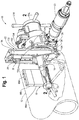
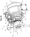
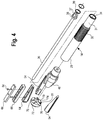
- a device 10 for machining the distal end of a length of pipe 12 has an elongate central shaft or mandrel 14 at one end of which is a mounting assembly 16 for retaining the mandrel 14 axially aligned with the longitudinal axis of the pipe 12 and at the opposite end of which are housing portions 18 and 19 that assemble together and are non-rotatable with respect to the mandrel 14.
- the device also includes a motor 20, a rotating arm 22, and radially moveable along the arm 22 a tool holder 24 for retaining a cutting tool 26. When in operation, the arm 22 rotates around the mandrel 14 and the cutting tool 26 is moved by the tool holder 24 and the arm 22 to cut a compound bevel 27 at the outer end of the length of pipe 12.
- the device 10 includes an adjustable autofeed 28 that can adjustably fix the axial rate at which the housing 18, 19 is axially advanced with respect to the mandrel 14 thereby axially moving the arm 22 and the tool 26.
- the mounting portion 16 will be described as being at the rearward end of the device 10 and the housing 18, 19 positioned at the forward end thereof.
- the mandrel 14 has a rearward end retaining the mounting assembly 16 and a forward end retaining the housing 18, and all longitudinally oriented parts likewise have forward and rearward ends.
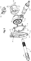
- annular end plate 72 On the distal end of the draw bar 36 is an annular end plate 72 having a forward surface 74 with a plurality of radially directed grooves 76 therein for receiving the rearward ends 67 of each chuck leg 54 and a threaded central opening 77 that threadedly receives the distal end of the draw bar 36.
- retaining screws Retained in mounting holes, not shown, adjacent to each of the grooves 76 are retaining screws, one of which 78 is shown.
- Each screw 78 has a head that engages the ridge 68 of one of the chuck legs 54, thereby slideably retaining the end of the chuck leg 54 to the end plate 72.
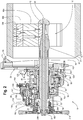
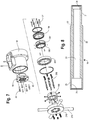
- a main shaft 90 rotatably mounted on bearings 86, 88 around the cylindrical portion 29 of the mandrel 14 immediately rearward of the splines 30 is a main shaft 90.
- the main shaft 90 is generally tubular in shape having a cylindrical inner opening 85 through with the mandrel 14 extends such that the main shaft 90 forms a sleeve rotatable around the mandrel 14.
- the forward end of the main shaft 90 has male threads 87, and rearward of the male threads 87 is a centrally located cylindrical section 89.
- a radial flange 92 At the rearward end of the main shaft 90.
- the rotating arm 22 includes a mounting plate 102 retained by a plurality of bolts, not visible, to the rearward surface of the flange 92 of the main shaft 90 for rotation therewith.
- On opposite sides of the rearward surface of the mounting plate 102 are stiffener plates 104, 106 for rigidly retaining the mounting plate 102.
- At the radially outward end of the mounting plate 102 and stiffeners 104, 106 is an end plate 108.
- a feed screw block 110 having a transverse hole 111 therein through which an elongate threaded feed screw 112 extends.
- the stiffener plates 104, 106 are oriented parallel to one another along the mounting plate 102 and form a channel along which a rectangular shaped male slide 114 is slideable.
- the slide 114 has a transverse threaded hole 116 therein for threadedly receiving the outer end of the feed screw 112.
- An enlarged diameter portion 122 of the feed screw 112 forms a thrust shoulder for applying force against a surface of the feed screw block 110 when the slide 114 it is moved radially outward.
- the distal end of the feed screw 112 has a star wheel 124 non-rotatably retained thereto such that rotation of the star wheel 124 rotates the feed screw 112 and causes radial movement of the slide 114.
- Mounted on the slide 114 is the tool holder 24 and cutting tool 26.
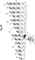
- each trip 128 consists of an elongate arm 130 with a handle at one end thereof and a centrally located transverse hole 121.
- Each trip 128 is mounted in a U-shaped retainer 132 on a pin 123 that extends through the centrally located transverse hole 121 of the moveable trip and through aligned holes in each of the parallel sides of the U-shaped trip retainer 132.
- an operator can position the various trips 128 into an engagement position, in which the trip is extended, or a non-engaging position, in which the trip is not extended, for engaging or not engaging the points of the star wheel 124 as the mounting plate 102 rotates around the mandrel 14. Accordingly, by setting or not setting the desired number of trips 128, an operator can determine the rate at which the star wheel 124 is rotated with respect to a single rotation of the mounting plate 104 and the tool 26 about the mandrel 14, and thereby controlling the speed of radial movement of the tool 26 with respect to the rotation of the mounting plate 102.
- a locking nut 134 has female threads 125 extending into the rearward end thereof that threadedly receive the threads 87 of the main shaft 90 and has a forward surface that abuts against the bearing 98, thereby retaining the bearings 98, 100 with respect to the main shaft 90.
- the forward end 127 of the outer surface of the locking nut 134 is frustoconical and the locking nut 134 is locked to the threads 87 of the main shaft 90 by an annular locking member 136 having an inner surface complementary to the frustoconical surface 127 of the lock nut 134 to ensure that the bearing lock nut and main shaft 90 rotate together.
- annular locking member 136 having an inner surface complementary to the frustoconical surface 127 of the lock nut 134 to ensure that the bearing lock nut and main shaft 90 rotate together.
- the rearward end of the outer surface 138 of the threaded locking nut 134 forms a cam against which moves a follower as is further described below.
- the cam 138 includes a gradual ramp portion 133 along which the radius is gradually lengthened and rapid fall section 135 extending between the maximum radius and minimum radius of the gradual ramp portion 133.
- the rearward portion of the cam follower 140 has a pair of spaced apart parallel ears 150, 152 with aligned transverse holes 157 therein and fitted between the ears 150, 152 and rotatable on a shaft 155 extending through the holes 157 in the ears 150, 152 is a rotatable roller 154 positioned to engage the outer surface of the cam 138.
- the cam follower 140 further has a third ear 156 positioned approximately diametrically opposite the first and second ears 150, 152.
- the third ear 156 has a threaded hole 158 therein for receiving a pin 160.
- Seals 169, 163 retain lubricants and retaining rings 165, 167 retain the parts around the cam shaft 142.
- the pin 160 in ear 156 receives one end of a coil spring 161, the opposite end of which connects to a pin 137 on an inner surface of the housing 18, not shown, to urge the cam follower 140 to rotate the roller 154 against the surface of the cam 138.
- a third bearing 146 rotatably retains the rearward end of the cam shaft 142 with respect to the cam follower 140. Accordingly, movement of the cam follower 140 and roller 154 against the outer surface of the cam 138 causes angular rotation of the cam follower 140 on the shaft 142.
- the first one-way clutch 166 applies an incremental angular rotation to the shaft 142 in one direction with each rotation of the cam 138 and reversal of the cam shaft 142 is prevented by the second one-way clutch 170.
- the lower end of the longitudinal hole 171 opens into a rectangular opening 177 that extends transversely through the controlling arm 178.
- Loosely fitted into the rectangular opening 177 is an elongate locking plate 175 to which the second end of the threaded stud 173 is attached.
- One end of the locking plate 175 extends into an arcuate slot 179 in the end plate 181 that mates against housing portion 183.
- Turning the locking knob 184 in one direction draws the locking plate 175 against a surface forming arcuate slot 179 in the end plate 181 thereby locking the stop 172 in a desired position.
- the intermediary gear assembly 188 includes a second gear 190 that engages the cam shaft gear 168 and a third gear 192 that is locked for rotation with the second gear 190.
- the teeth of the third gear 192 engage the teeth 193 of a feed nut drive gear 194.
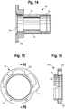
- the feed nut drive gear 194 has a large diameter central opening into which is fitted a tubular feed nut adapter 196.
- the feed nut adapter 196 is in turn retained by bolts 197 to a threaded feed nut 198 having internal threads 199 that engage the threaded forward end 31 of the mandrel 14.
- the assembled parts are rotatably retained with respect to the housing 18 by a bearing 201.
- the forward half of the inner opening of the feed nut drive gear 194 includes an annular rippled or serrated surface 200.
- the surface 200 has equally spaced apart crests 203 shaped as blunted teeth of a gear, and between each pair of crests 203, is a shallow, arcuate valley 205.
- the feed nut adapter 196 has a plurality of radial holes 202 therein that are aligned radially inward of the serrated surface 200 of the drive gear 194. Slideably fitted into each of the holes 202 is a detent ball 204.
- the angle of a cut made by the tool 26 is determined by the combination of the rate of radial movement of the slide 114 along the arms 22 and the rate of axial movement of the main shaft 90 along the mandrel 14.
- the radial movement of the slide is caused by rotation of the star wheel 124, which is incrementally rotated each time the star wheel 124 engages a trip 128 that is in the engagement position. If two trips 128 are set in the engagement position, the slide 114 and tool 26 will move at twice the radial rate relative to the axial movement of the main shaft 90 as when only one trip 128 is set.
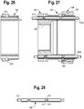
- One scale 184 is provided that has a marking that sets forth the angle to be cut by the tool 26 for various positions of the controlling arm 178 and marker 180 where one trip 128 is set in the engagement position. However, a second scale 184 is needed for setting the angle of the cut where two trips 128 are set, and a third scale 184 is needed for setting the angle of the cut when three trips 128 are set. As shown in Fig. 6 , the housing 183 may receive two or more scales 184 with each scale 184 showing angles to be cut for a different number of trips 128 set.
Landscapes
- Engineering & Computer Science (AREA)
- Mechanical Engineering (AREA)
- Turning (AREA)
Claims (10)
- Vorrichtung zum Bearbeiten eines Endes eines Rohrteilstücks, wobei die Vorrichtung Folgendes umfasst:einen länglichen Dorn (14),eine Hülse (90), die an dem Dorn drehbar angebracht ist,einen sich radial erstreckenden Arm (22) an der Hülse,ein Schneidwerkzeug (26) an dem Arm zum Bearbeiten des Endes des Rohrteilstücks, wenn sich der Arm dreht,einen Motor (20) zum Drehen der Hülse und des Arms,
wobei die Hülse längs des Dorns axial bewegt werden kann,ein Gewinde (31) an dem Dorn,eine Vorschubmutter (198), die für einen axialen Vortrieb der Hülse längs des Dorns mit dem Gewinde in Eingriff gelangt, gekennzeichnet durch:wobei die Welle mit der Vorschubmutter antriebstechnisch verbunden ist, wobei die Hülse und das Schneidwerkzeug mit jeder Drehung der Hülse längs des Dorns axial vorangetrieben werden.einen Nocken (138) an der Hülse,einen Nockenstößel (140), der mit dem Nocken in Eingriff ist,
wobei der Nockenstößel um eine Welle (142) gedreht werden kann,einen Freilauf (166) zwischen dem Nockenstößel und der Welle, wobei eine Drehbewegung des Nockenstößels nur in einer Richtung auf die Welle übertragen wird, und - Vorrichtung nach Anspruch 1, die ferner Folgendes umfasst:eine Klemme (40) an einem Ende des Dorns,wobei die Klemme mehrere radial bewegliche Beine (54) zum Eingreifen in eine Innenfläche des Rohrs aufweist.
- Vorrichtung nach Anspruch 2, die ferner Folgendes umfasst:abnehmbare Schuhe (66), die an den radial beweglichen Beinen (54) befestigt werden können,wobei die beweglichen Schuhe in mehreren unterschiedlichen Längen verfügbar sind und wobei die Schuhe in Längsrichtung gestapelt werden können, wobei mehrere Größen der Schuhe für einen Eingriff in die Klemme für mehrere Größen von Rohrdurchmessern kombiniert werden können.
- Vorrichtung nach einem der vorhergehenden Ansprüche, die ferner Folgendes umfasst:das Schneidwerkzeug, das längs des Arms radial bewegt werden kann,eine längs des Arms axial drehbare Zugspindel (112), undeinen Antrieb zum Drehen der Zugspindel in Reaktion auf eine Drehung der Hülse um den Dorn.
- Vorrichtung nach Anspruch 4, die ferner Folgendes umfasst:ein Gewinde an der Zugspindel, undeine nicht drehbare Folgermutter (114) und die Zugspindel,
wobei die Folgermutter an dem Schneidwerkzeug befestigt ist, wobei das Schneidwerkzeug in Reaktion auf eine Drehung des Arms um die Welle radial bewegt wird. - Vorrichtung nach einem der vorhergehenden Ansprüche, die ferner Folgendes umfasst:ein einstellbares Anschlagelement (172) zum Begrenzen eines Drehwinkels des Nockenstößels um die Welle, wobei eine Neupositionierung des Anschlagelements eine Geschwindigkeit ändert, mit der die Vorschubmutter die Hülse und das Schneidwerkzeug vorantreibt.
- Vorrichtung nach Anspruch 6, die ferner Folgendes umfasst:ein Markierungselement (180), das mit dem Anschlagelement bewegt werden kann, undeine Skala (182), die Markierungen aufweist, die entsprechende axiale Vorschubgeschwindigkeiten anzeigen, wobei die Positionierung des Markierungselements bei einer gewählten Vorschubgeschwindigkeit auf der Skala zur Folge hat, dass die Hülse und das Schneidwerkzeug mit der gewählten Geschwindigkeit vorangetrieben werden.
- Vorrichtung nach einem der vorhergehenden Ansprüche, die ferner eine manuelle Kupplung zwischen dem Dorn und der Vorschubmutter umfasst.
- Vorrichtung nach Anspruch 8, die ferner Folgendes umfasst:ein Antriebsrad (194) um die Vorschubmutter,
wobei das Antriebsrad eine gezahnte Innenfläche (200) aufweist,
wobei die gezahnte Innenfläche mehrere gleichmäßig voneinander beabstandete Kränze (203) und eine Mulde (205) zwischen jedem Paar Kränze aufweist,
wobei die Vorschubmutter wenigstens ein radiales Loch (202) aufweist, das sich in eine Außenfläche davon erstreckt,
wobei die Vorschubmutter ferner ein axial ausgerichtetes quer verlaufendes Loch (206) aufweist, dessen Achse die Achse des wenigstens einen radialen Lochs schneidet,eine Kugel (204) in wenigstens einem radialen Loch,einen Schaltstift (208) in dem axial ausgerichteten Loch,wobei der Schaltstift eine Nut quer zu seiner Länge aufweist, wobei die Kugel in die Nut fallen kann, wenn die Nut auf das radiale Loch ausgerichtet ist, und wobei die Kugel in eine der Mulden der gezahnten Oberfläche gedrängt wird, wenn die Nut nicht auf das radiale Loch ausgerichtet ist, und
wobei der Schaltstift zwischen einer ersten Position, in der die Nut auf das radiale Loch ausgerichtet ist, und einer zweiten Position, in der die Nut nicht auf das radiale Loch ausgerichtet ist, bewegt werden kann. - Vorrichtung nach Anspruch 1, die ferner einen zweiten Freilauf an der Welle umfasst, wobei der zweite Freilauf als hinterer Anschlag konfiguriert ist, um eine Drehung der Welle entgegengesetzt zu der Drehung, die durch den Nockenstößel auferlegt wird, zu verhindern.
Applications Claiming Priority (3)
| Application Number | Priority Date | Filing Date | Title |
|---|---|---|---|
| US23576809P | 2009-08-21 | 2009-08-21 | |
| US12/574,775 US9114458B2 (en) | 2009-08-21 | 2009-10-07 | Pipe end machining device with axial autofeed |
| PCT/US2010/046006 WO2011066005A2 (en) | 2009-08-21 | 2010-08-19 | Pipe end machining device with axial autofeed |
Publications (2)
| Publication Number | Publication Date |
|---|---|
| EP2467225A2 EP2467225A2 (de) | 2012-06-27 |
| EP2467225B1 true EP2467225B1 (de) | 2017-02-01 |
Family
ID=43604231
Family Applications (1)
| Application Number | Title | Priority Date | Filing Date |
|---|---|---|---|
| EP10819693.2A Active EP2467225B1 (de) | 2009-08-21 | 2010-08-19 | Rohrendenbearbeitungsgerät mit automatischem axialen vorschub |
Country Status (4)
| Country | Link |
|---|---|
| US (2) | US9114458B2 (de) |
| EP (1) | EP2467225B1 (de) |
| CA (1) | CA2770686C (de) |
| WO (1) | WO2011066005A2 (de) |
Families Citing this family (22)
| Publication number | Priority date | Publication date | Assignee | Title |
|---|---|---|---|---|
| DE102009019867A1 (de) * | 2009-05-06 | 2010-11-18 | Illinois Tool Works Inc., Glenview | Rohrbearbeitungsvorrichtung zum Bearbeiten eines rohrförmigen Körpers |
| US8935973B2 (en) * | 2011-01-19 | 2015-01-20 | Colin Denis LEBLANC | Bevelling apparatus for pipe re-facing machine |
| US9050669B2 (en) | 2012-10-04 | 2015-06-09 | Illinois Tool Works Inc. | Rapidly retractable tool support for a pipe machining apparatus |
| US9610636B2 (en) | 2013-01-09 | 2017-04-04 | Illinois Tool Works Inc. | Pipe machining apparatuses and methods of operating the same |
| US9623484B2 (en) * | 2013-01-14 | 2017-04-18 | Illinois Tool Works Inc. | Pipe machining apparatuses and methods of operating the same |
| WO2015026771A1 (en) * | 2013-08-19 | 2015-02-26 | Reface Systems, LLC | Tubular connection refacing apparatus and methods |
| WO2015051111A1 (en) | 2013-10-03 | 2015-04-09 | Illinois Tool Works Inc. | Pivotal tool support for a pipe machining apparatus |
| US10065246B2 (en) | 2015-04-13 | 2018-09-04 | Illinois Tool Works Inc. | Laser line generator tool for a pipe machining apparatus |
| US9901997B2 (en) * | 2015-06-24 | 2018-02-27 | Illinois Tool Works Inc. | Pipe cutting apparatus, kit, and method |
| US9849525B2 (en) | 2015-06-24 | 2017-12-26 | Illinois Tool Works Inc. | Pipe cutting apparatus, kit, and method |
| US10376963B2 (en) * | 2015-07-09 | 2019-08-13 | Illinois Tool Works Inc. | Pipe end machining device |
| WO2017027776A1 (en) | 2015-08-12 | 2017-02-16 | Illinois Tool Works Inc. | Crash resistant trip for a pipe for a machining apparatus |
| HUE070173T2 (hu) * | 2016-03-01 | 2025-05-28 | Fischer G Rohrleitungssysteme Ag | Hántoló és vágó szerszám |
| US9868182B1 (en) * | 2017-05-16 | 2018-01-16 | Jeffery A. Smith | Safe mode cross slide system |
| US10413971B1 (en) * | 2016-03-10 | 2019-09-17 | Jeffery A. Smith | Safe mode cross slide system |
| US10675692B2 (en) | 2016-08-25 | 2020-06-09 | Illinois Tool Works Inc. | Systems, apparatuses and methods of machining pipes and/or pipe flanges |
| HUE067311T2 (hu) * | 2017-10-11 | 2024-10-28 | Fischer G Rohrleitungssysteme Ag | Eljárás és berendezés elõszigetelt csövek szigetelésmentesítésére |
| US11123800B2 (en) * | 2018-02-07 | 2021-09-21 | Concurrent Technologies Corporation | Pipe edge preparation tool |
| CN108543956B (zh) * | 2018-05-17 | 2024-02-23 | 于伟忱 | 便携式数控管件平头倒角机 |
| US11958119B2 (en) | 2019-07-15 | 2024-04-16 | Climax Portable Machine Tools, Inc. | Portable lathes, portable lathe assembly kits, and associated methods |
| CN110788351B (zh) * | 2019-11-12 | 2020-11-03 | 陕西韩阳工程技术研发有限公司 | 一种外卡式管道切割坡口设备 |
| CN113618146B (zh) * | 2021-08-05 | 2024-04-12 | 山东荣智金属制造有限公司 | 一种薄壁钢管防变形切割装置 |
Family Cites Families (30)
| Publication number | Priority date | Publication date | Assignee | Title |
|---|---|---|---|---|
| US4149436A (en) * | 1977-12-13 | 1979-04-17 | Blattler Joseph F | Machine for facing seal faces of pipes |
| US4207786A (en) * | 1978-07-03 | 1980-06-17 | Tri Tool, Inc. | Cam follower tool arrangement |
| US4437366A (en) * | 1981-04-03 | 1984-03-20 | Tri Tool, Inc. | Tool carrier for portable lathe |
| US4411178A (en) * | 1981-06-04 | 1983-10-25 | Power Cutting Incorporated | Pipe end preparation machine |
| US4483223A (en) * | 1983-04-07 | 1984-11-20 | Tri Tool Inc. | Portable lathe |
| US4543861A (en) * | 1984-05-11 | 1985-10-01 | The E. H. Wachs Company | Portable lathe |
| US4614136A (en) * | 1984-11-26 | 1986-09-30 | Tri-Tool | Angularly adjustable mandrel assembly |
| US4677884A (en) * | 1985-04-05 | 1987-07-07 | The E. H. Wachs Company | Portable end prep lathe |
| JP2747523B2 (ja) | 1986-06-03 | 1998-05-06 | コスモ工機 株式会社 | 可搬式管開先加工機 |
| US4823655A (en) * | 1986-09-08 | 1989-04-25 | Tri Tool Inc. | Multi-speed drive system for a portable lathe |
| US4739685A (en) * | 1987-01-12 | 1988-04-26 | Ricci Donato L | Split frame portable machining lathe |
| US4981055A (en) * | 1989-03-30 | 1991-01-01 | Tri Tool Inc. | Portable facing tool |
| TW206182B (de) * | 1991-04-30 | 1993-05-21 | Sumitomo Chemical Co | |
| US5570608A (en) * | 1995-02-06 | 1996-11-05 | Miller; Robert H. | Power transmission |
| US5642969A (en) * | 1995-07-13 | 1997-07-01 | Climax Portable Machine Tools, Inc. | Portable machine tool |
| US5775188A (en) * | 1996-02-29 | 1998-07-07 | Climax Portable Machine Tools, Inc. | Apparatus for and method of facing surfaces |
| EP0810140B1 (de) * | 1996-05-30 | 2000-04-19 | Koyo Seiko Co., Ltd. | Welle für die Drehmomentübertragung in einer Lenkeinheit und Verfahren für ihren Zusammenbau |
| US5894772A (en) * | 1997-02-18 | 1999-04-20 | Nodar; Felix | Portable pipe machining tool |
| US6050161A (en) * | 1998-10-23 | 2000-04-18 | Tri Tool Inc. | Portable single-point beveling tool |
| US6202522B1 (en) * | 1999-05-27 | 2001-03-20 | Tri Tool Inc. | Portable pipe end preparation machine tool |
| US6189425B1 (en) * | 1999-10-13 | 2001-02-20 | Donato L. Ricci | Rapid end prep lathe |
| US6508413B2 (en) * | 2000-04-06 | 2003-01-21 | Siemens Westinghouse Power Corporation | Remote spray coating of nuclear cross-under piping |
| US6615696B2 (en) * | 2001-12-10 | 2003-09-09 | Donato L. Ricci | Oval manway facing machine |
| US6994002B2 (en) * | 2003-03-27 | 2006-02-07 | Esco Technologies, Inc. | End prep tool and tool centering and mounting system for use therewith |
| US7793574B2 (en) * | 2005-08-22 | 2010-09-14 | Climax Portable Machine Tools Inc. | Machine tool |
| CA2647050A1 (en) * | 2006-03-22 | 2007-11-01 | D.L. Ricci Corp. | Tapered turning lathe |
| US7383758B2 (en) * | 2006-06-14 | 2008-06-10 | D.L. Ricci Corp. | Air-operated end prep machine |
| US8250953B2 (en) * | 2008-12-31 | 2012-08-28 | H&S Tool, Inc. | Tripper assembly for a clamshell lathe |
| CA2767559C (en) * | 2009-08-03 | 2014-05-13 | Honda Motor Co., Ltd. | Multistage transmission |
| EP2681405B1 (de) * | 2011-02-28 | 2018-11-28 | Neil H. Akkerman | Trennanordnung für zylindrische bauteile |
-
2009
- 2009-10-07 US US12/574,775 patent/US9114458B2/en active Active
-
2010
- 2010-08-19 EP EP10819693.2A patent/EP2467225B1/de active Active
- 2010-08-19 WO PCT/US2010/046006 patent/WO2011066005A2/en not_active Ceased
- 2010-08-19 CA CA2770686A patent/CA2770686C/en active Active
-
2015
- 2015-07-20 US US14/803,176 patent/US10137504B2/en active Active
Non-Patent Citations (1)
| Title |
|---|
| None * |
Also Published As
| Publication number | Publication date |
|---|---|
| CA2770686A1 (en) | 2011-06-03 |
| CA2770686C (en) | 2014-05-20 |
| WO2011066005A2 (en) | 2011-06-03 |
| EP2467225A2 (de) | 2012-06-27 |
| US10137504B2 (en) | 2018-11-27 |
| US20110041658A1 (en) | 2011-02-24 |
| US9114458B2 (en) | 2015-08-25 |
| WO2011066005A3 (en) | 2011-11-03 |
| US20150321259A1 (en) | 2015-11-12 |
Similar Documents
| Publication | Publication Date | Title |
|---|---|---|
| EP2467225B1 (de) | Rohrendenbearbeitungsgerät mit automatischem axialen vorschub | |
| US4483223A (en) | Portable lathe | |
| EP0067204B1 (de) | Werkzeughalter für drehendes schneidwerzeug | |
| US11383338B2 (en) | Tool driving device, tool feeding mechanism for tool rotating unit and hole processing method | |
| JPH0310442B2 (de) | ||
| US10076792B2 (en) | Portable boring machine | |
| US2365549A (en) | Grooving tool | |
| WO2016045632A1 (zh) | 一种成型刀具及加工工件的方法、成型设备 | |
| EP1123171B1 (de) | Anfaswerkzeug mit einer schneidkante | |
| EP2558261B1 (de) | Maschinenanordnung mit auf verschiedene positionen einstellbarem getriebe | |
| US5605084A (en) | Squaring machine for various sized tubes | |
| US4813822A (en) | Power drill system with adjustable depth sensing means | |
| US3229555A (en) | Pipe-end finishing machine | |
| EP2271453B1 (de) | Rohrtrenn- und -anfaswerkzeug | |
| US4260303A (en) | Boring tools | |
| US4094216A (en) | Rapidly adjustable tool | |
| JP5693298B2 (ja) | 自動旋回割出機能付きアングルヘッド | |
| US5083484A (en) | Pipe end preparation tool having improved torque reacting and clamping capabilities | |
| US4577532A (en) | Automatic device for advancement of revolving mechanical organs | |
| EP0619158B1 (de) | Rohrendbearbeitungswerkzeug mit verbesserten Torsionreaktion und Spannmöglichkeiten | |
| US5692422A (en) | Squaring machine | |
| DE1958412A1 (de) | Tragbares Motorwerkzeug | |
| US6112627A (en) | Squaring machine | |
| US11534876B2 (en) | Machining assembly comprising a first and a second electric motor, a drive unit and a feed module | |
| CN110636917B (zh) | 机床的刀架 |
Legal Events
| Date | Code | Title | Description |
|---|---|---|---|
| PUAI | Public reference made under article 153(3) epc to a published international application that has entered the european phase |
Free format text: ORIGINAL CODE: 0009012 |
|
| 17P | Request for examination filed |
Effective date: 20120313 |
|
| AK | Designated contracting states |
Kind code of ref document: A2 Designated state(s): AL AT BE BG CH CY CZ DE DK EE ES FI FR GB GR HR HU IE IS IT LI LT LU LV MC MK MT NL NO PL PT RO SE SI SK SM TR |
|
| DAX | Request for extension of the european patent (deleted) | ||
| RAP1 | Party data changed (applicant data changed or rights of an application transferred) |
Owner name: ILLINOIS TOOL WORKS INC. |
|
| GRAP | Despatch of communication of intention to grant a patent |
Free format text: ORIGINAL CODE: EPIDOSNIGR1 |
|
| INTG | Intention to grant announced |
Effective date: 20160317 |
|
| GRAJ | Information related to disapproval of communication of intention to grant by the applicant or resumption of examination proceedings by the epo deleted |
Free format text: ORIGINAL CODE: EPIDOSDIGR1 |
|
| GRAP | Despatch of communication of intention to grant a patent |
Free format text: ORIGINAL CODE: EPIDOSNIGR1 |
|
| INTG | Intention to grant announced |
Effective date: 20160811 |
|
| GRAS | Grant fee paid |
Free format text: ORIGINAL CODE: EPIDOSNIGR3 |
|
| STAA | Information on the status of an ep patent application or granted ep patent |
Free format text: STATUS: GRANT OF PATENT IS INTENDED |
|
| GRAJ | Information related to disapproval of communication of intention to grant by the applicant or resumption of examination proceedings by the epo deleted |
Free format text: ORIGINAL CODE: EPIDOSDIGR1 |
|
| GRAL | Information related to payment of fee for publishing/printing deleted |
Free format text: ORIGINAL CODE: EPIDOSDIGR3 |
|
| STAA | Information on the status of an ep patent application or granted ep patent |
Free format text: STATUS: REQUEST FOR EXAMINATION WAS MADE |
|
| GRAR | Information related to intention to grant a patent recorded |
Free format text: ORIGINAL CODE: EPIDOSNIGR71 |
|
| STAA | Information on the status of an ep patent application or granted ep patent |
Free format text: STATUS: GRANT OF PATENT IS INTENDED |
|
| GRAA | (expected) grant |
Free format text: ORIGINAL CODE: 0009210 |
|
| STAA | Information on the status of an ep patent application or granted ep patent |
Free format text: STATUS: THE PATENT HAS BEEN GRANTED |
|
| INTC | Intention to grant announced (deleted) | ||
| INTG | Intention to grant announced |
Effective date: 20161222 |
|
| AK | Designated contracting states |
Kind code of ref document: B1 Designated state(s): AL AT BE BG CH CY CZ DE DK EE ES FI FR GB GR HR HU IE IS IT LI LT LU LV MC MK MT NL NO PL PT RO SE SI SK SM TR |
|
| REG | Reference to a national code |
Ref country code: GB Ref legal event code: FG4D |
|
| REG | Reference to a national code |
Ref country code: AT Ref legal event code: REF Ref document number: 865125 Country of ref document: AT Kind code of ref document: T Effective date: 20170215 Ref country code: CH Ref legal event code: EP |
|
| REG | Reference to a national code |
Ref country code: IE Ref legal event code: FG4D |
|
| REG | Reference to a national code |
Ref country code: DE Ref legal event code: R096 Ref document number: 602010039942 Country of ref document: DE |
|
| REG | Reference to a national code |
Ref country code: NL Ref legal event code: FP |
|
| REG | Reference to a national code |
Ref country code: LT Ref legal event code: MG4D |
|
| REG | Reference to a national code |
Ref country code: AT Ref legal event code: MK05 Ref document number: 865125 Country of ref document: AT Kind code of ref document: T Effective date: 20170201 |
|
| PG25 | Lapsed in a contracting state [announced via postgrant information from national office to epo] |
Ref country code: IS Free format text: LAPSE BECAUSE OF FAILURE TO SUBMIT A TRANSLATION OF THE DESCRIPTION OR TO PAY THE FEE WITHIN THE PRESCRIBED TIME-LIMIT Effective date: 20170601 Ref country code: GR Free format text: LAPSE BECAUSE OF FAILURE TO SUBMIT A TRANSLATION OF THE DESCRIPTION OR TO PAY THE FEE WITHIN THE PRESCRIBED TIME-LIMIT Effective date: 20170502 Ref country code: HR Free format text: LAPSE BECAUSE OF FAILURE TO SUBMIT A TRANSLATION OF THE DESCRIPTION OR TO PAY THE FEE WITHIN THE PRESCRIBED TIME-LIMIT Effective date: 20170201 Ref country code: NO Free format text: LAPSE BECAUSE OF FAILURE TO SUBMIT A TRANSLATION OF THE DESCRIPTION OR TO PAY THE FEE WITHIN THE PRESCRIBED TIME-LIMIT Effective date: 20170501 Ref country code: LT Free format text: LAPSE BECAUSE OF FAILURE TO SUBMIT A TRANSLATION OF THE DESCRIPTION OR TO PAY THE FEE WITHIN THE PRESCRIBED TIME-LIMIT Effective date: 20170201 Ref country code: FI Free format text: LAPSE BECAUSE OF FAILURE TO SUBMIT A TRANSLATION OF THE DESCRIPTION OR TO PAY THE FEE WITHIN THE PRESCRIBED TIME-LIMIT Effective date: 20170201 |
|
| REG | Reference to a national code |
Ref country code: FR Ref legal event code: PLFP Year of fee payment: 8 |
|
| PG25 | Lapsed in a contracting state [announced via postgrant information from national office to epo] |
Ref country code: AT Free format text: LAPSE BECAUSE OF FAILURE TO SUBMIT A TRANSLATION OF THE DESCRIPTION OR TO PAY THE FEE WITHIN THE PRESCRIBED TIME-LIMIT Effective date: 20170201 Ref country code: LV Free format text: LAPSE BECAUSE OF FAILURE TO SUBMIT A TRANSLATION OF THE DESCRIPTION OR TO PAY THE FEE WITHIN THE PRESCRIBED TIME-LIMIT Effective date: 20170201 Ref country code: BG Free format text: LAPSE BECAUSE OF FAILURE TO SUBMIT A TRANSLATION OF THE DESCRIPTION OR TO PAY THE FEE WITHIN THE PRESCRIBED TIME-LIMIT Effective date: 20170501 Ref country code: SE Free format text: LAPSE BECAUSE OF FAILURE TO SUBMIT A TRANSLATION OF THE DESCRIPTION OR TO PAY THE FEE WITHIN THE PRESCRIBED TIME-LIMIT Effective date: 20170201 Ref country code: ES Free format text: LAPSE BECAUSE OF FAILURE TO SUBMIT A TRANSLATION OF THE DESCRIPTION OR TO PAY THE FEE WITHIN THE PRESCRIBED TIME-LIMIT Effective date: 20170201 Ref country code: PL Free format text: LAPSE BECAUSE OF FAILURE TO SUBMIT A TRANSLATION OF THE DESCRIPTION OR TO PAY THE FEE WITHIN THE PRESCRIBED TIME-LIMIT Effective date: 20170201 Ref country code: PT Free format text: LAPSE BECAUSE OF FAILURE TO SUBMIT A TRANSLATION OF THE DESCRIPTION OR TO PAY THE FEE WITHIN THE PRESCRIBED TIME-LIMIT Effective date: 20170601 |
|
| PG25 | Lapsed in a contracting state [announced via postgrant information from national office to epo] |
Ref country code: CZ Free format text: LAPSE BECAUSE OF FAILURE TO SUBMIT A TRANSLATION OF THE DESCRIPTION OR TO PAY THE FEE WITHIN THE PRESCRIBED TIME-LIMIT Effective date: 20170201 Ref country code: RO Free format text: LAPSE BECAUSE OF FAILURE TO SUBMIT A TRANSLATION OF THE DESCRIPTION OR TO PAY THE FEE WITHIN THE PRESCRIBED TIME-LIMIT Effective date: 20170201 Ref country code: EE Free format text: LAPSE BECAUSE OF FAILURE TO SUBMIT A TRANSLATION OF THE DESCRIPTION OR TO PAY THE FEE WITHIN THE PRESCRIBED TIME-LIMIT Effective date: 20170201 Ref country code: SK Free format text: LAPSE BECAUSE OF FAILURE TO SUBMIT A TRANSLATION OF THE DESCRIPTION OR TO PAY THE FEE WITHIN THE PRESCRIBED TIME-LIMIT Effective date: 20170201 |
|
| REG | Reference to a national code |
Ref country code: DE Ref legal event code: R097 Ref document number: 602010039942 Country of ref document: DE |
|
| PG25 | Lapsed in a contracting state [announced via postgrant information from national office to epo] |
Ref country code: DK Free format text: LAPSE BECAUSE OF FAILURE TO SUBMIT A TRANSLATION OF THE DESCRIPTION OR TO PAY THE FEE WITHIN THE PRESCRIBED TIME-LIMIT Effective date: 20170201 Ref country code: SM Free format text: LAPSE BECAUSE OF FAILURE TO SUBMIT A TRANSLATION OF THE DESCRIPTION OR TO PAY THE FEE WITHIN THE PRESCRIBED TIME-LIMIT Effective date: 20170201 |
|
| PLBE | No opposition filed within time limit |
Free format text: ORIGINAL CODE: 0009261 |
|
| STAA | Information on the status of an ep patent application or granted ep patent |
Free format text: STATUS: NO OPPOSITION FILED WITHIN TIME LIMIT |
|
| 26N | No opposition filed |
Effective date: 20171103 |
|
| PG25 | Lapsed in a contracting state [announced via postgrant information from national office to epo] |
Ref country code: SI Free format text: LAPSE BECAUSE OF FAILURE TO SUBMIT A TRANSLATION OF THE DESCRIPTION OR TO PAY THE FEE WITHIN THE PRESCRIBED TIME-LIMIT Effective date: 20170201 |
|
| REG | Reference to a national code |
Ref country code: CH Ref legal event code: PL |
|
| PG25 | Lapsed in a contracting state [announced via postgrant information from national office to epo] |
Ref country code: MC Free format text: LAPSE BECAUSE OF FAILURE TO SUBMIT A TRANSLATION OF THE DESCRIPTION OR TO PAY THE FEE WITHIN THE PRESCRIBED TIME-LIMIT Effective date: 20170201 |
|
| PG25 | Lapsed in a contracting state [announced via postgrant information from national office to epo] |
Ref country code: CH Free format text: LAPSE BECAUSE OF NON-PAYMENT OF DUE FEES Effective date: 20170831 Ref country code: LI Free format text: LAPSE BECAUSE OF NON-PAYMENT OF DUE FEES Effective date: 20170831 |
|
| REG | Reference to a national code |
Ref country code: IE Ref legal event code: MM4A |
|
| REG | Reference to a national code |
Ref country code: BE Ref legal event code: MM Effective date: 20170831 |
|
| PG25 | Lapsed in a contracting state [announced via postgrant information from national office to epo] |
Ref country code: LU Free format text: LAPSE BECAUSE OF NON-PAYMENT OF DUE FEES Effective date: 20170819 |
|
| PG25 | Lapsed in a contracting state [announced via postgrant information from national office to epo] |
Ref country code: IE Free format text: LAPSE BECAUSE OF NON-PAYMENT OF DUE FEES Effective date: 20170819 |
|
| REG | Reference to a national code |
Ref country code: FR Ref legal event code: PLFP Year of fee payment: 9 |
|
| PG25 | Lapsed in a contracting state [announced via postgrant information from national office to epo] |
Ref country code: BE Free format text: LAPSE BECAUSE OF NON-PAYMENT OF DUE FEES Effective date: 20170831 |
|
| PG25 | Lapsed in a contracting state [announced via postgrant information from national office to epo] |
Ref country code: MT Free format text: LAPSE BECAUSE OF NON-PAYMENT OF DUE FEES Effective date: 20170819 |
|
| PG25 | Lapsed in a contracting state [announced via postgrant information from national office to epo] |
Ref country code: HU Free format text: LAPSE BECAUSE OF FAILURE TO SUBMIT A TRANSLATION OF THE DESCRIPTION OR TO PAY THE FEE WITHIN THE PRESCRIBED TIME-LIMIT; INVALID AB INITIO Effective date: 20100819 |
|
| PG25 | Lapsed in a contracting state [announced via postgrant information from national office to epo] |
Ref country code: CY Free format text: LAPSE BECAUSE OF NON-PAYMENT OF DUE FEES Effective date: 20170201 |
|
| PG25 | Lapsed in a contracting state [announced via postgrant information from national office to epo] |
Ref country code: MK Free format text: LAPSE BECAUSE OF FAILURE TO SUBMIT A TRANSLATION OF THE DESCRIPTION OR TO PAY THE FEE WITHIN THE PRESCRIBED TIME-LIMIT Effective date: 20170201 |
|
| PG25 | Lapsed in a contracting state [announced via postgrant information from national office to epo] |
Ref country code: TR Free format text: LAPSE BECAUSE OF FAILURE TO SUBMIT A TRANSLATION OF THE DESCRIPTION OR TO PAY THE FEE WITHIN THE PRESCRIBED TIME-LIMIT Effective date: 20170201 |
|
| PG25 | Lapsed in a contracting state [announced via postgrant information from national office to epo] |
Ref country code: AL Free format text: LAPSE BECAUSE OF FAILURE TO SUBMIT A TRANSLATION OF THE DESCRIPTION OR TO PAY THE FEE WITHIN THE PRESCRIBED TIME-LIMIT Effective date: 20170201 |
|
| P01 | Opt-out of the competence of the unified patent court (upc) registered |
Effective date: 20230606 |
|
| PGFP | Annual fee paid to national office [announced via postgrant information from national office to epo] |
Ref country code: NL Payment date: 20250826 Year of fee payment: 16 |
|
| PGFP | Annual fee paid to national office [announced via postgrant information from national office to epo] |
Ref country code: DE Payment date: 20250827 Year of fee payment: 16 |
|
| PGFP | Annual fee paid to national office [announced via postgrant information from national office to epo] |
Ref country code: IT Payment date: 20250820 Year of fee payment: 16 |
|
| PGFP | Annual fee paid to national office [announced via postgrant information from national office to epo] |
Ref country code: GB Payment date: 20250827 Year of fee payment: 16 |
|
| PGFP | Annual fee paid to national office [announced via postgrant information from national office to epo] |
Ref country code: FR Payment date: 20250825 Year of fee payment: 16 |