EP2467225B1 - Pipe end machining device with axial autofeed - Google Patents
Pipe end machining device with axial autofeed Download PDFInfo
- Publication number
- EP2467225B1 EP2467225B1 EP10819693.2A EP10819693A EP2467225B1 EP 2467225 B1 EP2467225 B1 EP 2467225B1 EP 10819693 A EP10819693 A EP 10819693A EP 2467225 B1 EP2467225 B1 EP 2467225B1
- Authority
- EP
- European Patent Office
- Prior art keywords
- shaft
- mandrel
- sleeve
- feed
- arm
- Prior art date
- Legal status (The legal status is an assumption and is not a legal conclusion. Google has not performed a legal analysis and makes no representation as to the accuracy of the status listed.)
- Active
Links
Images


Classifications
-
- B—PERFORMING OPERATIONS; TRANSPORTING
- B23—MACHINE TOOLS; METAL-WORKING NOT OTHERWISE PROVIDED FOR
- B23B—TURNING; BORING
- B23B5/00—Turning-machines or devices specially adapted for particular work; Accessories specially adapted therefor
- B23B5/16—Turning-machines or devices specially adapted for particular work; Accessories specially adapted therefor for bevelling, chamfering, or deburring the ends of bars or tubes
- B23B5/161—Devices attached to the workpiece
- B23B5/162—Devices attached to the workpiece with an internal clamping device
-
- B—PERFORMING OPERATIONS; TRANSPORTING
- B23—MACHINE TOOLS; METAL-WORKING NOT OTHERWISE PROVIDED FOR
- B23B—TURNING; BORING
- B23B5/00—Turning-machines or devices specially adapted for particular work; Accessories specially adapted therefor
- B23B5/16—Turning-machines or devices specially adapted for particular work; Accessories specially adapted therefor for bevelling, chamfering, or deburring the ends of bars or tubes
- B23B5/167—Tools for chamfering the ends of bars or tubes
- B23B5/168—Tools for chamfering the ends of bars or tubes with guiding devices
-
- B—PERFORMING OPERATIONS; TRANSPORTING
- B23—MACHINE TOOLS; METAL-WORKING NOT OTHERWISE PROVIDED FOR
- B23B—TURNING; BORING
- B23B2260/00—Details of constructional elements
- B23B2260/004—Adjustable elements
-
- B—PERFORMING OPERATIONS; TRANSPORTING
- B23—MACHINE TOOLS; METAL-WORKING NOT OTHERWISE PROVIDED FOR
- B23B—TURNING; BORING
- B23B2260/00—Details of constructional elements
- B23B2260/104—Markings, i.e. symbols or other indicating marks
-
- Y—GENERAL TAGGING OF NEW TECHNOLOGICAL DEVELOPMENTS; GENERAL TAGGING OF CROSS-SECTIONAL TECHNOLOGIES SPANNING OVER SEVERAL SECTIONS OF THE IPC; TECHNICAL SUBJECTS COVERED BY FORMER USPC CROSS-REFERENCE ART COLLECTIONS [XRACs] AND DIGESTS
- Y10—TECHNICAL SUBJECTS COVERED BY FORMER USPC
- Y10T—TECHNICAL SUBJECTS COVERED BY FORMER US CLASSIFICATION
- Y10T82/00—Turning
- Y10T82/22—Portable lathe for pipe turning
Definitions
- the operator can therefore rotate the feed screw at a first rate, for example, one revolution of the screw for each revolution of the cutting tool to form a first bevel angle of thirty-seven degrees and then change the feed rate, for example, to three rotations of the feed screw for each rotation of the cutting tool to cut a bevel at ten degrees.
- a first rate for example, one revolution of the screw for each revolution of the cutting tool to form a first bevel angle of thirty-seven degrees
- change the feed rate for example, to three rotations of the feed screw for each rotation of the cutting tool to cut a bevel at ten degrees.
- the operation of such a machine requires constant attention from the operator. It may take forty-five minutes or longer for a machine to cut a bevel at the distal end of a length of pipe, and if the operator fails to properly adjust the feed screw after each revolution or sequence of revolutions of the cutting tool, the bevel will not be properly formed. It would be desirable, therefore, to provide a device for machining the end of a length of pipe that
- a cutting tool suitable for cutting the pipe is radially moveable along the arm and a drive radially moves the tool as the sleeve rotates about the shaft thereby providing a linear relationship between rotation of the sleeve and radial movement of the tool.
- the device further includes a control for controlling the outer limits of movement of the cam follower thereby controlling the rate at which the gearing is rotated thereby controlling the rate of axial movement of the feed screw and axial movement of the cutting tool. Accordingly, adjustment of the control changes the limits of movement of the cam follower and changes the axial speed of the cutting tool, thereby changing the angle of the bevel being cut. By merely changing the control, the device will change the angle of the bevel being cut without requiring an operator to reconfigure the machine.
- a device 10 for machining the distal end of a length of pipe 12 has an elongate central shaft or mandrel 14 at one end of which is a mounting assembly 16 for retaining the mandrel 14 axially aligned with the longitudinal axis of the pipe 12 and at the opposite end of which are housing portions 18 and 19 that assemble together and are non-rotatable with respect to the mandrel 14.
- the device also includes a motor 20, a rotating arm 22, and radially moveable along the arm 22 a tool holder 24 for retaining a cutting tool 26. When in operation, the arm 22 rotates around the mandrel 14 and the cutting tool 26 is moved by the tool holder 24 and the arm 22 to cut a compound bevel 27 at the outer end of the length of pipe 12.
- the device 10 includes an adjustable autofeed 28 that can adjustably fix the axial rate at which the housing 18, 19 is axially advanced with respect to the mandrel 14 thereby axially moving the arm 22 and the tool 26.
- the mounting portion 16 will be described as being at the rearward end of the device 10 and the housing 18, 19 positioned at the forward end thereof.
- the mandrel 14 has a rearward end retaining the mounting assembly 16 and a forward end retaining the housing 18, and all longitudinally oriented parts likewise have forward and rearward ends.
- annular end plate 72 On the distal end of the draw bar 36 is an annular end plate 72 having a forward surface 74 with a plurality of radially directed grooves 76 therein for receiving the rearward ends 67 of each chuck leg 54 and a threaded central opening 77 that threadedly receives the distal end of the draw bar 36.
- retaining screws Retained in mounting holes, not shown, adjacent to each of the grooves 76 are retaining screws, one of which 78 is shown.
- Each screw 78 has a head that engages the ridge 68 of one of the chuck legs 54, thereby slideably retaining the end of the chuck leg 54 to the end plate 72.
- a main shaft 90 rotatably mounted on bearings 86, 88 around the cylindrical portion 29 of the mandrel 14 immediately rearward of the splines 30 is a main shaft 90.
- the main shaft 90 is generally tubular in shape having a cylindrical inner opening 85 through with the mandrel 14 extends such that the main shaft 90 forms a sleeve rotatable around the mandrel 14.
- the forward end of the main shaft 90 has male threads 87, and rearward of the male threads 87 is a centrally located cylindrical section 89.
- a radial flange 92 At the rearward end of the main shaft 90.
- the rotating arm 22 includes a mounting plate 102 retained by a plurality of bolts, not visible, to the rearward surface of the flange 92 of the main shaft 90 for rotation therewith.
- On opposite sides of the rearward surface of the mounting plate 102 are stiffener plates 104, 106 for rigidly retaining the mounting plate 102.
- At the radially outward end of the mounting plate 102 and stiffeners 104, 106 is an end plate 108.
- a feed screw block 110 having a transverse hole 111 therein through which an elongate threaded feed screw 112 extends.
- the stiffener plates 104, 106 are oriented parallel to one another along the mounting plate 102 and form a channel along which a rectangular shaped male slide 114 is slideable.
- the slide 114 has a transverse threaded hole 116 therein for threadedly receiving the outer end of the feed screw 112.
- An enlarged diameter portion 122 of the feed screw 112 forms a thrust shoulder for applying force against a surface of the feed screw block 110 when the slide 114 it is moved radially outward.
- the distal end of the feed screw 112 has a star wheel 124 non-rotatably retained thereto such that rotation of the star wheel 124 rotates the feed screw 112 and causes radial movement of the slide 114.
- Mounted on the slide 114 is the tool holder 24 and cutting tool 26.
- each trip 128 consists of an elongate arm 130 with a handle at one end thereof and a centrally located transverse hole 121.
- Each trip 128 is mounted in a U-shaped retainer 132 on a pin 123 that extends through the centrally located transverse hole 121 of the moveable trip and through aligned holes in each of the parallel sides of the U-shaped trip retainer 132.
- an operator can position the various trips 128 into an engagement position, in which the trip is extended, or a non-engaging position, in which the trip is not extended, for engaging or not engaging the points of the star wheel 124 as the mounting plate 102 rotates around the mandrel 14. Accordingly, by setting or not setting the desired number of trips 128, an operator can determine the rate at which the star wheel 124 is rotated with respect to a single rotation of the mounting plate 104 and the tool 26 about the mandrel 14, and thereby controlling the speed of radial movement of the tool 26 with respect to the rotation of the mounting plate 102.
- a locking nut 134 has female threads 125 extending into the rearward end thereof that threadedly receive the threads 87 of the main shaft 90 and has a forward surface that abuts against the bearing 98, thereby retaining the bearings 98, 100 with respect to the main shaft 90.
- the forward end 127 of the outer surface of the locking nut 134 is frustoconical and the locking nut 134 is locked to the threads 87 of the main shaft 90 by an annular locking member 136 having an inner surface complementary to the frustoconical surface 127 of the lock nut 134 to ensure that the bearing lock nut and main shaft 90 rotate together.
- annular locking member 136 having an inner surface complementary to the frustoconical surface 127 of the lock nut 134 to ensure that the bearing lock nut and main shaft 90 rotate together.
- the rearward end of the outer surface 138 of the threaded locking nut 134 forms a cam against which moves a follower as is further described below.
- the cam 138 includes a gradual ramp portion 133 along which the radius is gradually lengthened and rapid fall section 135 extending between the maximum radius and minimum radius of the gradual ramp portion 133.
- the rearward portion of the cam follower 140 has a pair of spaced apart parallel ears 150, 152 with aligned transverse holes 157 therein and fitted between the ears 150, 152 and rotatable on a shaft 155 extending through the holes 157 in the ears 150, 152 is a rotatable roller 154 positioned to engage the outer surface of the cam 138.
- the cam follower 140 further has a third ear 156 positioned approximately diametrically opposite the first and second ears 150, 152.
- the third ear 156 has a threaded hole 158 therein for receiving a pin 160.
- Seals 169, 163 retain lubricants and retaining rings 165, 167 retain the parts around the cam shaft 142.
- the pin 160 in ear 156 receives one end of a coil spring 161, the opposite end of which connects to a pin 137 on an inner surface of the housing 18, not shown, to urge the cam follower 140 to rotate the roller 154 against the surface of the cam 138.
- a third bearing 146 rotatably retains the rearward end of the cam shaft 142 with respect to the cam follower 140. Accordingly, movement of the cam follower 140 and roller 154 against the outer surface of the cam 138 causes angular rotation of the cam follower 140 on the shaft 142.
- the first one-way clutch 166 applies an incremental angular rotation to the shaft 142 in one direction with each rotation of the cam 138 and reversal of the cam shaft 142 is prevented by the second one-way clutch 170.
- the lower end of the longitudinal hole 171 opens into a rectangular opening 177 that extends transversely through the controlling arm 178.
- Loosely fitted into the rectangular opening 177 is an elongate locking plate 175 to which the second end of the threaded stud 173 is attached.
- One end of the locking plate 175 extends into an arcuate slot 179 in the end plate 181 that mates against housing portion 183.
- Turning the locking knob 184 in one direction draws the locking plate 175 against a surface forming arcuate slot 179 in the end plate 181 thereby locking the stop 172 in a desired position.
- the intermediary gear assembly 188 includes a second gear 190 that engages the cam shaft gear 168 and a third gear 192 that is locked for rotation with the second gear 190.
- the teeth of the third gear 192 engage the teeth 193 of a feed nut drive gear 194.
- the feed nut drive gear 194 has a large diameter central opening into which is fitted a tubular feed nut adapter 196.
- the feed nut adapter 196 is in turn retained by bolts 197 to a threaded feed nut 198 having internal threads 199 that engage the threaded forward end 31 of the mandrel 14.
- the assembled parts are rotatably retained with respect to the housing 18 by a bearing 201.
- the forward half of the inner opening of the feed nut drive gear 194 includes an annular rippled or serrated surface 200.
- the surface 200 has equally spaced apart crests 203 shaped as blunted teeth of a gear, and between each pair of crests 203, is a shallow, arcuate valley 205.
- the feed nut adapter 196 has a plurality of radial holes 202 therein that are aligned radially inward of the serrated surface 200 of the drive gear 194. Slideably fitted into each of the holes 202 is a detent ball 204.
- the angle of a cut made by the tool 26 is determined by the combination of the rate of radial movement of the slide 114 along the arms 22 and the rate of axial movement of the main shaft 90 along the mandrel 14.
- the radial movement of the slide is caused by rotation of the star wheel 124, which is incrementally rotated each time the star wheel 124 engages a trip 128 that is in the engagement position. If two trips 128 are set in the engagement position, the slide 114 and tool 26 will move at twice the radial rate relative to the axial movement of the main shaft 90 as when only one trip 128 is set.
- One scale 184 is provided that has a marking that sets forth the angle to be cut by the tool 26 for various positions of the controlling arm 178 and marker 180 where one trip 128 is set in the engagement position. However, a second scale 184 is needed for setting the angle of the cut where two trips 128 are set, and a third scale 184 is needed for setting the angle of the cut when three trips 128 are set. As shown in Fig. 6 , the housing 183 may receive two or more scales 184 with each scale 184 showing angles to be cut for a different number of trips 128 set.
Landscapes
- Engineering & Computer Science (AREA)
- Mechanical Engineering (AREA)
- Turning (AREA)
Description
- The present invention relates to a device according to the preamble of claim 1, for machining the end of a pipe to provide a bevel suitable for welding, and in particular to an autodrive for machining a compound bevel angle without requiring the reconfiguration of the machine.
- Such a device is already known from
US 4 677 884 A1 . - Extended piping requires that shorter lengths of pipe be welded together end to end to form a longer section and prior to joining two lengths together, the mated ends must be machined to receive a weld. Where the wall of the pipe is relatively thin, the distal end of the pipe may be machined into a simple bevel. Where the wall of the pipe is thicker, a compound bevel is required. A typical compound bevel has one portion angled at ten degrees and a second portion angled at thirty-seven degrees.
- Machines that bevel the distal end of a length of pipe are elongate with a first end structured to engage the inner surface of a length of pipe and retain the machine rigid with respect to the pipe. The second end of the machine includes a rotating member with a cutting end. Some machines can be configured to automatically cut a bevel at a fixed angle, for example, cut at ten degrees. Such machines must be reconfigured if they are subsequently required to cut a second portion of a bevel at thirty-seven degrees. Other machines move the tool radially at a fixed rate and provide a manually operable feed screw for moving the tool axially. The rate at which the axial feed screw is operated determines the angle of the bevel being cut. The operator can therefore rotate the feed screw at a first rate, for example, one revolution of the screw for each revolution of the cutting tool to form a first bevel angle of thirty-seven degrees and then change the feed rate, for example, to three rotations of the feed screw for each rotation of the cutting tool to cut a bevel at ten degrees. However, the operation of such a machine requires constant attention from the operator. It may take forty-five minutes or longer for a machine to cut a bevel at the distal end of a length of pipe, and if the operator fails to properly adjust the feed screw after each revolution or sequence of revolutions of the cutting tool, the bevel will not be properly formed. It would be desirable, therefore, to provide a device for machining the end of a length of pipe that is capable of forming a compound bevel without requiring the reconfiguration of the machine or requiring that an operator manually rotate a feed screw.
-
US 4,677,884 discloses an end prep lathe which is presettable to control the angle of a bevel cut on a pipe in response to rotation of a tool head. - Briefly, the present invention is a device according to claim 1, for preparing the end of a length of pipe , that includes an elongate non-rotatable shaft having a clamp at one end that includes a plurality of moveable shoes for applying force to the inner surface of a length of pipe to thereby retain the shaft to the pipe. A housing at the second end of the shaft retains a sleeve rotatable around the shaft and an arm extending radially from the sleeve. A motor rotates the sleeve and the arm, and the sleeve is axially moveable along the shaft.
- A cutting tool suitable for cutting the pipe is radially moveable along the arm and a drive radially moves the tool as the sleeve rotates about the shaft thereby providing a linear relationship between rotation of the sleeve and radial movement of the tool.
- A portion of the shaft has a threading and a feed screw rotates on the threading for axially advancing the sleeve. The rotating sleeve has an annular cam surface thereon that moves a cam follower mounted on the housing. Movement of the cam follower is converted into rotational movement that rotates a gearing connected to the feed screw for advancing the sleeve along the shaft in response to movement of the cam follower.
- In a preferred embodiment, the device further includes a control for controlling the outer limits of movement of the cam follower thereby controlling the rate at which the gearing is rotated thereby controlling the rate of axial movement of the feed screw and axial movement of the cutting tool. Accordingly, adjustment of the control changes the limits of movement of the cam follower and changes the axial speed of the cutting tool, thereby changing the angle of the bevel being cut. By merely changing the control, the device will change the angle of the bevel being cut without requiring an operator to reconfigure the machine.
- A better understanding of the invention will be had after a reading of the following detailed description taken in conjunction with the drawings wherein:
-
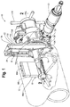
Fig. 1 is an isometric view of a device in accordance with the present invention; -
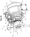
Fig. 1A is another isometric view of the device taken from the opposite side, with a portion of the housing broken away; -
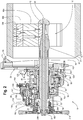
Fig. 2 is a cross-sectional view of the device shown inFig. 1 attached to a length of pipe; -
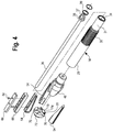
Fig. 3 is an exploded view of the device show inFig. 1 , showing the major components thereof; -
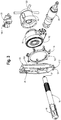
Fig. 4 is an exploded view of the mounting assembly for retaining the device shown inFigs. 1 and2 to the length of pipe; -
Fig. 5 is an exploded view of the facing arm of the device shownFigs. 1 and2 that engages and cuts the distal end of a length of pipe; -
Fig. 6 is an exploded view of the autofeed assembly that provides rotational power for axially moving the facing arm shown inFig. 5 ; -
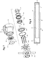
Fig. 7 is an exploded view of the feed that axially drives the facing arm and cutting tool shown inFig. 5 ; -
Fig. 8 is a cross-sectional view of the mandrel shown inFigs. 2 and3 ; -
Fig. 9 is a side elevational view of the chuck shown inFig. 4 ; -
Fig. 10 is a cross-sectional view of the chuck shown inFig. 9 ; -
Fig. 11 is a rear end view of the chuck shown inFig. 9 ; -
Fig. 12 is a side elevational view of one of the chuck legs shown inFig. 4 ; -
Fig. 13 is an elevational view of the outer end of the chuck leg shown inFig. 12 ; -
Fig. 14 is a cross-sectional view of the main shaft shown inFig. 2 ; -
Fig. 15 is an end view of a locking nut and cam shown inFig. 2 ; -
Fig. 16 is a cross-sectional view of the locking nut and cam shown inFig. 15 taken through line 16 - 16 thereof; -
Fig. 17 is a side elevational view of the cam follower shaft shown inFig. 6 ; -
Fig. 18 is a side elevational view of the cam follower shown inFig. 6 ; -
Fig. 19 is an end view of the cam follower shown inFig. 18 ; -
Fig. 20 is a side elevational view of the stop, the stop shaft, and the stop adjusting arm assembled together and visible inFig. 2 ; -
Fig. 21 is an end view of the stop, the stop shaft, and the stop adjusting arm as shown inFig. 20 ; -
Fig. 22 is a side elevational view of the intermediary gears and shaft shown inFigs. 2 and29 ; -
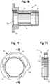
Fig. 23 is a rear end view of the feed nut drive gear shown inFig. 7 ; -
Fig. 24 is a cross-sectional view of the feed nut drive gear shown inFig. 23 taken through line 24 - 24 thereof; -
Fig. 25 is a front end view of the feed nut drive gear shown inFig. 23 ; -
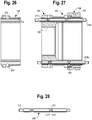
Fig. 26 is a cross-sectional view of the feed nut adapter shown inFig. 7 ; -
Fig. 27 is a cross-sectional view of the feed nut drive gear assembled to the feed nut adapter shown inFig. 26 and the feed nut shown inFig. 23 with two shifter pins inserted into the assembled parts; -
Fig. 28 is a side elevational view of a shifter pin shown inFigs. 7 and27 ; -
Fig. 29 is an isometric view of the cam follower, the stop, the scale for adjusting the stop, and the intermediary gears driven by the cam follower shaft, and -
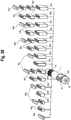
Fig. 30 shows a collection of different sizes of shoes attachable to the device shown inFigs. 1 and2 to accommodate a range of sizes of pipe. - Referring to
Figs. 1 ,2 , and3 , adevice 10 for machining the distal end of a length ofpipe 12 has an elongate central shaft ormandrel 14 at one end of which is amounting assembly 16 for retaining themandrel 14 axially aligned with the longitudinal axis of thepipe 12 and at the opposite end of which arehousing portions mandrel 14. The device also includes amotor 20, arotating arm 22, and radially moveable along the arm 22 atool holder 24 for retaining acutting tool 26. When in operation, thearm 22 rotates around themandrel 14 and thecutting tool 26 is moved by thetool holder 24 and thearm 22 to cut acompound bevel 27 at the outer end of the length ofpipe 12. - To cut a
compound bevel 27, thedevice 10 includes anadjustable autofeed 28 that can adjustably fix the axial rate at which thehousing mandrel 14 thereby axially moving thearm 22 and thetool 26. For the purposes of this discussion, the mountingportion 16 will be described as being at the rearward end of thedevice 10 and thehousing mandrel 14 has a rearward end retaining the mountingassembly 16 and a forward end retaining thehousing 18, and all longitudinally oriented parts likewise have forward and rearward ends. - Referring to
Figs. 2 ,4 , and8 , themandrel 14 is a hollow cylinder, the outer surface of which has a rearwardcylindrical portion 29. Forward of thecylindrical portion 29 are centrally locatedsplines 30, and forward of thesplines 30 is a smaller diameter threadedportion 31. Aradial shoulder 32 defines the intersection between thesplines 30 and the forward threadedportion 31. Thecentral opening 33 of themandrel 14 is cylindrical. Anannular shoulder 34 is spaced a short distance from the forward end of themandrel 14 andfemale threads 35 extend a short distance into the rearward end thereof. - Rotatably mounted within the
mandrel 14 is an elongate threadeddraw bar 36 having ahex nut 37 non-rotatably mounted to the outer end thereof such that an operator can rotate thehex nut 37 and thedraw bar 36 using a conventional hand wrench, not shown. Anannular flange 38 at the rearward end of thenut 37, axially retains thedraw bar 36 with respect to the inner surface of themandrel 14. The rearward surface of theflange 38 abuts theannular shoulder 34 in the inner surface of themandrel 14 and the forward surface of theflange 38 abuts anannular retainer 39 to thereby retain thedraw bar 36 against axial movement with respect to themandrel 14. - Referring to
Figs. 2 ,4 ,8 ,9, 10, 11 ,12,13 , and30 , the mountingassembly 16 at the rear end of themandrel 14 includes achuck body 40 that is symmetrical about its longitudinal axis and at the forward end of which is a cylindrical threadedportion 41 that is threadedly received in thefemale threads 35 at the rearward end of themandrel 14. The rearward end of thechuck body 40 has a plurality ofgrooves 42 therein equally spaced around the circumference thereof. Each of thegrooves 42 has a rampedbottom surface 44 and opposing side surfaces 46, 48, one of which 48 has an associated undercut 50 therein. An axial hole 51 extends through the length of thechuck body 40 that rotatably receives thedraw bar 36. - Slideably fitted within each of the
grooves 42 is a wedge-shapedchuck leg 54 having alower surface 56 adapted to slide along thebottom surface 44 of one of thegrooves 42. One of the opposingwalls 52 of each of thechuck legs 54 is indented forming aridge 58 along one side of thelower surface 56 which are slideably received within the undercut 50 of thechuck body 40. Eachchuck leg 54 also has a generally planarupper surface 60 having at least two tappedholes 62 therein for receiving retaining screws 64 for retaining one or more sets ofremovable shoes 66. Therearward end 67 of eachchuck leg 54 also has atransverse groove 69 therein thereby forming aridge 68 along the rear face of thechuck leg 54 that is perpendicular to theupper surface 60. - The
shoes 66 that are attachable to theouter surface 60 of eachleg 54 are preferably available in a plurality of lengths. As depicted inFig. 30 , the shoes may be available in four distinct lengths with shoe 66A being the longest and shoe 66D being the shortest. By assembling different combinations of shoe lengths to eachleg 54, the length of thelegs 54 can be adjusted to retain themandrel 14 in any diameter ofpipe 12. - On the distal end of the
draw bar 36 is anannular end plate 72 having aforward surface 74 with a plurality of radially directedgrooves 76 therein for receiving the rearward ends 67 of eachchuck leg 54 and a threadedcentral opening 77 that threadedly receives the distal end of thedraw bar 36. Retained in mounting holes, not shown, adjacent to each of thegrooves 76 are retaining screws, one of which 78 is shown. Eachscrew 78 has a head that engages theridge 68 of one of thechuck legs 54, thereby slideably retaining the end of thechuck leg 54 to theend plate 72. Accordingly, rotation of thehex nut 37 at the forward end of thedraw bar 36 will rotate thedraw bar 36 and cause axial movement of theend plate 72. Axial movement of theend plate 72 toward thehex nut 37 will move all of thechuck legs 54 upwardly along the ramp surfaces 44 and force theremovable shoes 66 to move radially outward until they engage the inner surface of the central opening of thepipe 12 thereby locking and retaining themandrel 14 coaxial with thepipe 12. Rotation of thehex nut 34 in the opposite direction will withdraw the shoes and release themandrel 14 from thepipe 12. - Referring to
Figs. 2 and7 , surrounding thecentral portion 30 of themandrel 14 is anannular coupling 80 havingfemale splines 82 for slideably engaging thesplines 30 of themandrel 14. A plurality ofscrews 83 extend through holes, unnumbered, in thecoupling 80 and into a retaining flange that forms part of thehousing 18 to retain thehousing 18 against rotation with respect to themandrel 14 and allow thehousing 18 to move axially with respect to themandrel 14. - Referring to
Figs. 2 and14 , rotatably mounted onbearings cylindrical portion 29 of themandrel 14 immediately rearward of thesplines 30 is amain shaft 90. Themain shaft 90 is generally tubular in shape having a cylindricalinner opening 85 through with themandrel 14 extends such that themain shaft 90 forms a sleeve rotatable around themandrel 14. The forward end of themain shaft 90 hasmale threads 87, and rearward of themale threads 87 is a centrally locatedcylindrical section 89. At the rearward end of themain shaft 90 is aradial flange 92. Aworm gear 94 is fitted around the centralcylindrical section 89 and theworm gear 94 is driven by aworm shaft 96 mounted on a shaft from themotor 20. Theworm gear 94 is retained with respect to themain shaft 90 by a key, not visible, in a key slot. Another set ofbearings main shaft 90 with respect to thehousing 18. - Referring to
Figs. 1 ,2 ,3 , and5 , therotating arm 22 includes a mountingplate 102 retained by a plurality of bolts, not visible, to the rearward surface of theflange 92 of themain shaft 90 for rotation therewith. On opposite sides of the rearward surface of the mountingplate 102 arestiffener plates plate 102. At the radially outward end of the mountingplate 102 andstiffeners end plate 108. At the opposite end of theplate 102 is afeed screw block 110 having atransverse hole 111 therein through which an elongate threadedfeed screw 112 extends. - The
stiffener plates plate 102 and form a channel along which a rectangular shapedmale slide 114 is slideable. Theslide 114 has a transverse threadedhole 116 therein for threadedly receiving the outer end of thefeed screw 112. Anenlarged diameter portion 122 of thefeed screw 112 forms a thrust shoulder for applying force against a surface of thefeed screw block 110 when theslide 114 it is moved radially outward. The distal end of thefeed screw 112 has astar wheel 124 non-rotatably retained thereto such that rotation of thestar wheel 124 rotates thefeed screw 112 and causes radial movement of theslide 114. Mounted on theslide 114 is thetool holder 24 and cuttingtool 26. - As best shown in
Figs. 2 ,3 , and5 , mounted around the circumference ofhousing member 19 and adjacent the mountingplate 102 is anannular trip retainer 126. Positioned at equally spaced locations around the circumference of thetrip retainer 126 are a plurality ofmoveable trips 128. Eachtrip 128 consists of anelongate arm 130 with a handle at one end thereof and a centrally locatedtransverse hole 121. Eachtrip 128 is mounted in aU-shaped retainer 132 on apin 123 that extends through the centrally locatedtransverse hole 121 of the moveable trip and through aligned holes in each of the parallel sides of theU-shaped trip retainer 132. Using the handles of thevarious trips 128, an operator can position thevarious trips 128 into an engagement position, in which the trip is extended, or a non-engaging position, in which the trip is not extended, for engaging or not engaging the points of thestar wheel 124 as the mountingplate 102 rotates around themandrel 14. Accordingly, by setting or not setting the desired number oftrips 128, an operator can determine the rate at which thestar wheel 124 is rotated with respect to a single rotation of the mountingplate 104 and thetool 26 about themandrel 14, and thereby controlling the speed of radial movement of thetool 26 with respect to the rotation of the mountingplate 102. - Referring to
Figs. 1A ,2 ,15, and 16 , a lockingnut 134 hasfemale threads 125 extending into the rearward end thereof that threadedly receive thethreads 87 of themain shaft 90 and has a forward surface that abuts against the bearing 98, thereby retaining thebearings main shaft 90. Theforward end 127 of the outer surface of the lockingnut 134 is frustoconical and the lockingnut 134 is locked to thethreads 87 of themain shaft 90 by anannular locking member 136 having an inner surface complementary to thefrustoconical surface 127 of thelock nut 134 to ensure that the bearing lock nut andmain shaft 90 rotate together. As best shown inFig. 15 , the rearward end of theouter surface 138 of the threadedlocking nut 134 forms a cam against which moves a follower as is further described below. Thecam 138 includes agradual ramp portion 133 along which the radius is gradually lengthened andrapid fall section 135 extending between the maximum radius and minimum radius of thegradual ramp portion 133. - Referring to
Figs. 1A ,2 ,6 , and17 through 19 , a fundamental element of the present invention is the provision of theadjustable autofeed 28 for moving thehousing 18 along themandrel 14 at a rate that can be changed without reconfiguring the machine to thereby form acompound bevel 27. The heart of theadjustable autofeed 28 lies in acam follower 140 mounted on ashaft 142. Theshaft 142 has a threadedforward end 137. Rearward of the threadedforward end 137 is a firstcylindrical portion 139, and rearward of the firstcylindrical portion 139 is a second, larger diametercylindrical portion 141. Along the rearward half of the secondcylindrical portion 141 is akey slot 143. Rearward of thekey slot 143 incylindrical portion 141 is a large diametercylindrical portion 145 having somewhat smallerdiameter side portions cam shaft 142 is an annular groove for receiving a snap ring, unnumbered. Thecamshaft 142 extends parallel to themandrel 14 with the forward end retained by abearing 144 in thehousing 18. Thecam follower 140 has a tubular body with a generally cylindrical outer surface. Theforward portion 151 of the outer surface is an uninterrupted cylinder so as to receivebearing 153 that rotatably retains thecam follower 140 in a portion of thehousing 18. The rearward portion of thecam follower 140 has a pair of spaced apartparallel ears transverse holes 157 therein and fitted between theears shaft 155 extending through theholes 157 in theears rotatable roller 154 positioned to engage the outer surface of thecam 138. Thecam follower 140 further has athird ear 156 positioned approximately diametrically opposite the first andsecond ears third ear 156 has a threadedhole 158 therein for receiving apin 160. - The
cam follower 140 is fitted around thelarge diameter portion 145 near the rearward end of thecam shaft 142, and between theenlarged diameter portion 145 and the body of thecam follower 140 is a one-way clutch 166. Forward of the one-way clutch 166, and mounted on the secondcylindrical portion 141 of thecam shaft 142 is agear 168 retained by a key, not visible, in thekey slot 143 for rotation with thecam shaft 142. Forward of thegear 168 is a second one-way clutch 170 configured as a backstop. The forward end of thecam shaft 142 extends through a hole, not visible, in aportion 183 of the housing and is non-rotatably retained thereto by acollar 159 on the threadedend 137 thereof.Seals rings cam shaft 142. Thepin 160 inear 156 receives one end of acoil spring 161, the opposite end of which connects to apin 137 on an inner surface of thehousing 18, not shown, to urge thecam follower 140 to rotate theroller 154 against the surface of thecam 138. Athird bearing 146 rotatably retains the rearward end of thecam shaft 142 with respect to thecam follower 140. Accordingly, movement of thecam follower 140 androller 154 against the outer surface of thecam 138 causes angular rotation of thecam follower 140 on theshaft 142. The first one-way clutch 166 applies an incremental angular rotation to theshaft 142 in one direction with each rotation of thecam 138 and reversal of thecam shaft 142 is prevented by the second one-way clutch 170. - Referring to
Figs. 1 ,2 ,6 ,20 ,21 , and29 , an important feature of theautodrive 28 is the provision of anadjustable stop 172 that limits movement of thecam follower 140. Theadjustable stop 172 is mounted on apivot arm 174 that is rotatable on ashaft 176 oriented coaxial with the rearward end of thecam shaft 142. Thestop 172 is adapted to abut thethird ear 156 of thecam follower 140 and thereby limit the return of theroller 154 to contact the smallest radius portion of thecam 138. Theshaft 176 extends through a housing andplate 181 and is rotated by acontrolling arm 178 attached by apin 173 to theshaft 176. Abushing 171 around theshaft 176 facilitates its rotation. At the outer end of thecontrolling arm 178 is amarker 180 that is moveable along ascale 182. Thescale 182 is affixed to the outer surface of theend plate 181 that fits against a portion ofhousing 183 enclosing theautofeed 28. Anend cap 217 encloses thecontrolling arm 178. Themarker 180 and thescale 182 are visible by an operator and thecontrolling arm 178 is locked into a desired orientation, as shown by themarker 180 andscale 182, by a lockingknob 184. The lockingknob 184 threadedly receives the end of a threadedstud 173 that extends slideably through alongitudinal hole 171 in the upper end of thecontrolling arm 178. The lower end of thelongitudinal hole 171 opens into a rectangular opening 177 that extends transversely through thecontrolling arm 178. Loosely fitted into the rectangular opening 177 is anelongate locking plate 175 to which the second end of the threadedstud 173 is attached. One end of thelocking plate 175 extends into anarcuate slot 179 in theend plate 181 that mates againsthousing portion 183. Turning the lockingknob 184 in one direction draws the lockingplate 175 against a surface formingarcuate slot 179 in theend plate 181 thereby locking thestop 172 in a desired position. By adjusting thecontrolling arm 178 an operator can control the range of movement of thecam follower 140 and thereby control the relationship between the rate of rotation of thecam follower shaft 142 with respect to the rotational rate of themain shaft 90. - As best shown in
Figs. 2 ,6 , and22 , extending parallel to themandrel 14 and thecam follower shaft 142 is yet anothershaft 186. Rotatably mounted onshaft 186 onbearings intermediary gear assembly 188. Theintermediary gear assembly 188 includes asecond gear 190 that engages thecam shaft gear 168 and athird gear 192 that is locked for rotation with thesecond gear 190. - Referring to
Figs. 2 ,7 , and22 through 28 , the teeth of thethird gear 192 engage theteeth 193 of a feednut drive gear 194. The feednut drive gear 194 has a large diameter central opening into which is fitted a tubularfeed nut adapter 196. Thefeed nut adapter 196 is in turn retained by bolts 197 to a threadedfeed nut 198 havinginternal threads 199 that engage the threaded forward end 31 of themandrel 14. The assembled parts are rotatably retained with respect to thehousing 18 by abearing 201. - The forward half of the inner opening of the feed
nut drive gear 194 includes an annular rippled orserrated surface 200. Thesurface 200 has equally spaced apart crests 203 shaped as blunted teeth of a gear, and between each pair ofcrests 203, is a shallow,arcuate valley 205. Thefeed nut adapter 196 has a plurality ofradial holes 202 therein that are aligned radially inward of theserrated surface 200 of thedrive gear 194. Slideably fitted into each of theholes 202 is adetent ball 204. Extending parallel to the axis of thefeed nut adapter 196 so as to intercept each of theradial holes 202 aretransverse holes 206 each of which slideably receives anelongate shifter pin 208. Centrally located along the length of each of the shifter pins 208 is anannular groove 210 having angled side surfaces 211, and at the forward end of eachshifter pin 208 is a threading 212. Each of the shifter pins 208 extends through corresponding alignedholes 213 in thefeed nut 198 with the threaded ends 212 received in complementary threaded holes, unnumbered, in an end plate 216 having a plurality of radially extending handles 218. The end plate 216 and the shifter pins 208 are therefore axially moveable with respect to themandrel 14, the feednut drive gear 194 and thefeed nut adapter 196.Fig. 2 depicts the end plate 216 compressed against the forward surface of thefeed nut 198. When theend plate 26 is in this position, the shifter pins 208 are moved to their rearward position. InFig. 27 , shifter pin 208B is depicted as being in the rearward position in which theannular groove 210 around the circumference of each of the shifter pins 208 is aligned under its associateddetent ball 204 allowing the ball the sink deep within its associatedradial hole 202 and not forced into theserrated surface 200 of thedrive gear 194. Thedrive gear 194 is thereby allowed to freely rotate around themandrel 14. On the other hand, when an operator manually pulls theend plate 116 away from the forward surface of thefeed screw 198, theannular grooves 210 of the shifter pins 208 are moved away from the associateddetent balls 204 as is shifter pin 208A inFig. 7 . Theballs 204 are then forced up theangled surfaces 211 of the shifter pins 208 so that they engage theserrated surface 200 of thedrive gear 194 and are forced into avalley 205 between twocrests 203 thereby drivingly connecting thedrive gear 194 to thefeed nut 198. When thedrive gear 194 is drivingly connected to thefeed nut 198, rotational movement of thecam follower shaft 142 is applied through thevarious gears feed nut 198 with respect to themandrel 14 thereby causing axial feed of thehousing 18 with respect to themandrel 14. The autofeed 28 is therefore engaged when the end plate 216 is pulled away from thehousing 18 and disengaged when the end plate 216 is compressed against the forward surface of thehousing 18. With theautodrive 28 in the disengaged orientation, that is with the end plate 216 compressed against the housing, as shown inFig. 2 , an operator can manually rotate thehandles 218 of the end plate 216 to provide a manual axial feed along themandrel 14. - The angular movement of the
cam follower 140 causes rotation of thecam shaft 142 and thefeed nut 198. Thestop 172 limits the angular rotation undertaken by thecam follower 140 with each rotation of thecam 138 and therefore, changing the position of thestop 172 changes the distance themain shaft 90 andtool 26 are advanced with each rotation of thearm 22. Thescale 182 has markings 220 thereon indicative of the axial speed at which themain shaft 90 andtool 26 will be advanced. By loosening the lockingknob 184, the operator can move themarker 180 to a position on thescale 182 indicative of a desired axial feed rate. - It should be apparent that the angle of a cut made by the
tool 26 is determined by the combination of the rate of radial movement of theslide 114 along thearms 22 and the rate of axial movement of themain shaft 90 along themandrel 14. The radial movement of the slide is caused by rotation of thestar wheel 124, which is incrementally rotated each time thestar wheel 124 engages atrip 128 that is in the engagement position. If twotrips 128 are set in the engagement position, theslide 114 andtool 26 will move at twice the radial rate relative to the axial movement of themain shaft 90 as when only onetrip 128 is set. Onescale 184 is provided that has a marking that sets forth the angle to be cut by thetool 26 for various positions of thecontrolling arm 178 andmarker 180 where onetrip 128 is set in the engagement position. However, asecond scale 184 is needed for setting the angle of the cut where twotrips 128 are set, and athird scale 184 is needed for setting the angle of the cut when threetrips 128 are set. As shown inFig. 6 , thehousing 183 may receive two ormore scales 184 with eachscale 184 showing angles to be cut for a different number oftrips 128 set. - To operate the device of the present invention an operator will select the desired combination of
removable shoes 66 to fit the size pipe to be machined and attach them by bolts to the outer ends of each of theslides 114. The retaining end of themandrel 14 is then extended into the length ofpipe 12 and thehex head 37 rotated with a wrench until thedevice 10 is firmly retained with respect to thepipe 12. Thereafter, the desired number oftrips 128 are set to fix the desired radial rate of movement of thecutting tool 26. The lockingnut 184 is loosened allowing movement of thecontrolling arm 178 andmarker 180 with respect to thescale 182 to set the desired feed rate after which the lockingknob 184 is tightened. Themotor 20 is then energized causing rotation of the mountingplate 102 around themandrel 14. Using thehandles 218 of the end plate 216 the operator can withdraw the end plate 216 to engage theautodrive 30 and cause thetool 26 to cut the desiredbevel 27 at the end of thepipe 12. - While the present invention has been described with respect to a single embodiment, it will be appreciated that many modifications and variations may be made without departing from the scope of the claims.
Claims (10)
- A device for preparing an end of a length of pipe, said device comprising
an elongate mandrel (14),
a sleeve (90) rotatably mounted on said mandrel,
a radially extending arm (22) on said sleeve,
a cutting tool (26) on said arm for machining said end of length of pipe as said arm rotates,
a motor (20) for rotating said sleeve and said arm,
said sleeve being axially moveable along said mandrel,
a threading (31) on said mandrel,
a feed nut (198) engaging said threading for axially advancing said sleeve along said mandrel, characterised by
a cam (138) on said sleeve,
a cam follower (140) engaging said cam,
said cam follower being rotatable about a shaft (142),
a one-way clutch (166) between said cam follower and said shaft wherein rotational movement of said cam follower is conveyed to said shaft in only one direction, and
said shaft being drivingly connected to said feed nut wherein said sleeve and
said cutting tool are axially advanced along said mandrel with each rotation of said sleeve. - The device of claim 1 and further comprising
a clamp (40) at one end of said mandrel
said clamp having a plurality of radially moveable legs (54) for engaging an inner surface of said pipe. - The device of claim 2 and further comprising
removable shoes (66) attachable to said radially moveable legs (54),
said moveable shoes available in a plurality of different lengths, and said shoes longitudinally stackable wherein a plurality of sizes of said shoes can be combined for engaging said clamp to a number of sizes of pipe diameters. - The device of any preceding claim and further comprising
said cutting tool radially moveable along said arm,
an axially rotatable feed shaft (112) along said arm, and
a drive for rotating said feed shaft in response to rotation of said sleeve about said mandrel. - The device of claim 4 and further comprising
a threading on said feed shaft,
a non-rotatable follower nut (114) and said feed shaft,
and said follower nut attached to said cutting tool, wherein said cutting tool is radially moved in response to rotation of said arm about said shaft. - The device of any preceding claim and further comprising
an adjustable stop (172) for limiting an angle of rotation of said cam
follower about said shaft wherein a repositioning of said stop will change a rate at which said feed nut advances said sleeve and said cutting tool. - The device of claim 6 and further comprising
a marker (180) movable with said stop, and
a scale (182) having markings thereon indicative of corresponding axial
feed rates wherein the positioning of said marker at a chosen feed rate on said scale will result in said sleeve and said cutting tool being advanced at said chosen rate. - The device of any preceding claim and further comprising a manual clutch between said mandrel and said feed nut.
- The device of claim 8 and further comprising
a drive gear (194) around said feed nut,
said drive gear having a serrated inner surface (200),
said serrated inner surface having a plurality of equally spaced apart crests (203) and a valley (205) between each pair of crests,
said feed nut having at least one radial hole (202) extending into an outer surface thereof,
said feed nut further having an axially directed transverse hole (206) the axis of which intercepts the axis of said at least one radial hole,
a ball (204) in said at least one radial hole,
a shifter pin (208) in said axially directed hole,
said shifter pin having a groove transverse to a length thereof wherein said ball may fall into said groove when said groove is aligned with said radial hole, and said ball is forced into one of said valleys of said serrated surface when said groove is not in alignment with said radial hole, and
said shifter pin axially moveable between a first position wherein said groove is aligned with said radial hole and a second position wherein said groove is not aligned with said radial hole. - The device of claim 1 and further comprising a second one-way clutch on said shaft, said second one-way clutch configured as a backstop to prevent rotation of said shaft opposite to said rotation imposed by said cam follower.
Applications Claiming Priority (3)
| Application Number | Priority Date | Filing Date | Title |
|---|---|---|---|
| US23576809P | 2009-08-21 | 2009-08-21 | |
| US12/574,775 US9114458B2 (en) | 2009-08-21 | 2009-10-07 | Pipe end machining device with axial autofeed |
| PCT/US2010/046006 WO2011066005A2 (en) | 2009-08-21 | 2010-08-19 | Pipe end machining device with axial autofeed |
Publications (2)
| Publication Number | Publication Date |
|---|---|
| EP2467225A2 EP2467225A2 (en) | 2012-06-27 |
| EP2467225B1 true EP2467225B1 (en) | 2017-02-01 |
Family
ID=43604231
Family Applications (1)
| Application Number | Title | Priority Date | Filing Date |
|---|---|---|---|
| EP10819693.2A Active EP2467225B1 (en) | 2009-08-21 | 2010-08-19 | Pipe end machining device with axial autofeed |
Country Status (4)
| Country | Link |
|---|---|
| US (2) | US9114458B2 (en) |
| EP (1) | EP2467225B1 (en) |
| CA (1) | CA2770686C (en) |
| WO (1) | WO2011066005A2 (en) |
Families Citing this family (22)
| Publication number | Priority date | Publication date | Assignee | Title |
|---|---|---|---|---|
| DE102009019867A1 (en) * | 2009-05-06 | 2010-11-18 | Illinois Tool Works Inc., Glenview | Pipe processing device for machining a tubular body |
| US8935973B2 (en) * | 2011-01-19 | 2015-01-20 | Colin Denis LEBLANC | Bevelling apparatus for pipe re-facing machine |
| US9050669B2 (en) | 2012-10-04 | 2015-06-09 | Illinois Tool Works Inc. | Rapidly retractable tool support for a pipe machining apparatus |
| US9610636B2 (en) | 2013-01-09 | 2017-04-04 | Illinois Tool Works Inc. | Pipe machining apparatuses and methods of operating the same |
| US9623484B2 (en) * | 2013-01-14 | 2017-04-18 | Illinois Tool Works Inc. | Pipe machining apparatuses and methods of operating the same |
| WO2015026771A1 (en) * | 2013-08-19 | 2015-02-26 | Reface Systems, LLC | Tubular connection refacing apparatus and methods |
| WO2015051111A1 (en) | 2013-10-03 | 2015-04-09 | Illinois Tool Works Inc. | Pivotal tool support for a pipe machining apparatus |
| US10065246B2 (en) | 2015-04-13 | 2018-09-04 | Illinois Tool Works Inc. | Laser line generator tool for a pipe machining apparatus |
| US9901997B2 (en) * | 2015-06-24 | 2018-02-27 | Illinois Tool Works Inc. | Pipe cutting apparatus, kit, and method |
| US9849525B2 (en) | 2015-06-24 | 2017-12-26 | Illinois Tool Works Inc. | Pipe cutting apparatus, kit, and method |
| US10376963B2 (en) * | 2015-07-09 | 2019-08-13 | Illinois Tool Works Inc. | Pipe end machining device |
| WO2017027776A1 (en) | 2015-08-12 | 2017-02-16 | Illinois Tool Works Inc. | Crash resistant trip for a pipe for a machining apparatus |
| HUE070173T2 (en) * | 2016-03-01 | 2025-05-28 | Fischer G Rohrleitungssysteme Ag | Peeling and cutting tool |
| US9868182B1 (en) * | 2017-05-16 | 2018-01-16 | Jeffery A. Smith | Safe mode cross slide system |
| US10413971B1 (en) * | 2016-03-10 | 2019-09-17 | Jeffery A. Smith | Safe mode cross slide system |
| US10675692B2 (en) | 2016-08-25 | 2020-06-09 | Illinois Tool Works Inc. | Systems, apparatuses and methods of machining pipes and/or pipe flanges |
| HUE067311T2 (en) * | 2017-10-11 | 2024-10-28 | Fischer G Rohrleitungssysteme Ag | Method and device for stripping pre-insulated pipes |
| US11123800B2 (en) * | 2018-02-07 | 2021-09-21 | Concurrent Technologies Corporation | Pipe edge preparation tool |
| CN108543956B (en) * | 2018-05-17 | 2024-02-23 | 于伟忱 | Portable numerical control pipe fitting flat head chamfering machine |
| US11958119B2 (en) | 2019-07-15 | 2024-04-16 | Climax Portable Machine Tools, Inc. | Portable lathes, portable lathe assembly kits, and associated methods |
| CN110788351B (en) * | 2019-11-12 | 2020-11-03 | 陕西韩阳工程技术研发有限公司 | Outer card formula pipeline cutting groove equipment |
| CN113618146B (en) * | 2021-08-05 | 2024-04-12 | 山东荣智金属制造有限公司 | Thin-wall steel pipe anti-deformation cutting device |
Family Cites Families (30)
| Publication number | Priority date | Publication date | Assignee | Title |
|---|---|---|---|---|
| US4149436A (en) * | 1977-12-13 | 1979-04-17 | Blattler Joseph F | Machine for facing seal faces of pipes |
| US4207786A (en) * | 1978-07-03 | 1980-06-17 | Tri Tool, Inc. | Cam follower tool arrangement |
| US4437366A (en) * | 1981-04-03 | 1984-03-20 | Tri Tool, Inc. | Tool carrier for portable lathe |
| US4411178A (en) * | 1981-06-04 | 1983-10-25 | Power Cutting Incorporated | Pipe end preparation machine |
| US4483223A (en) * | 1983-04-07 | 1984-11-20 | Tri Tool Inc. | Portable lathe |
| US4543861A (en) * | 1984-05-11 | 1985-10-01 | The E. H. Wachs Company | Portable lathe |
| US4614136A (en) * | 1984-11-26 | 1986-09-30 | Tri-Tool | Angularly adjustable mandrel assembly |
| US4677884A (en) * | 1985-04-05 | 1987-07-07 | The E. H. Wachs Company | Portable end prep lathe |
| JP2747523B2 (en) | 1986-06-03 | 1998-05-06 | コスモ工機 株式会社 | Portable pipe beveling machine |
| US4823655A (en) * | 1986-09-08 | 1989-04-25 | Tri Tool Inc. | Multi-speed drive system for a portable lathe |
| US4739685A (en) * | 1987-01-12 | 1988-04-26 | Ricci Donato L | Split frame portable machining lathe |
| US4981055A (en) * | 1989-03-30 | 1991-01-01 | Tri Tool Inc. | Portable facing tool |
| TW206182B (en) * | 1991-04-30 | 1993-05-21 | Sumitomo Chemical Co | |
| US5570608A (en) * | 1995-02-06 | 1996-11-05 | Miller; Robert H. | Power transmission |
| US5642969A (en) * | 1995-07-13 | 1997-07-01 | Climax Portable Machine Tools, Inc. | Portable machine tool |
| US5775188A (en) * | 1996-02-29 | 1998-07-07 | Climax Portable Machine Tools, Inc. | Apparatus for and method of facing surfaces |
| EP0810140B1 (en) * | 1996-05-30 | 2000-04-19 | Koyo Seiko Co., Ltd. | A power transmission shaft in a steering unit and assembly method thereof |
| US5894772A (en) * | 1997-02-18 | 1999-04-20 | Nodar; Felix | Portable pipe machining tool |
| US6050161A (en) * | 1998-10-23 | 2000-04-18 | Tri Tool Inc. | Portable single-point beveling tool |
| US6202522B1 (en) * | 1999-05-27 | 2001-03-20 | Tri Tool Inc. | Portable pipe end preparation machine tool |
| US6189425B1 (en) * | 1999-10-13 | 2001-02-20 | Donato L. Ricci | Rapid end prep lathe |
| US6508413B2 (en) * | 2000-04-06 | 2003-01-21 | Siemens Westinghouse Power Corporation | Remote spray coating of nuclear cross-under piping |
| US6615696B2 (en) * | 2001-12-10 | 2003-09-09 | Donato L. Ricci | Oval manway facing machine |
| US6994002B2 (en) * | 2003-03-27 | 2006-02-07 | Esco Technologies, Inc. | End prep tool and tool centering and mounting system for use therewith |
| US7793574B2 (en) * | 2005-08-22 | 2010-09-14 | Climax Portable Machine Tools Inc. | Machine tool |
| CA2647050A1 (en) * | 2006-03-22 | 2007-11-01 | D.L. Ricci Corp. | Tapered turning lathe |
| US7383758B2 (en) * | 2006-06-14 | 2008-06-10 | D.L. Ricci Corp. | Air-operated end prep machine |
| US8250953B2 (en) * | 2008-12-31 | 2012-08-28 | H&S Tool, Inc. | Tripper assembly for a clamshell lathe |
| CA2767559C (en) * | 2009-08-03 | 2014-05-13 | Honda Motor Co., Ltd. | Multistage transmission |
| EP2681405B1 (en) * | 2011-02-28 | 2018-11-28 | Neil H. Akkerman | Disconnect assembly for cylindrical members |
-
2009
- 2009-10-07 US US12/574,775 patent/US9114458B2/en active Active
-
2010
- 2010-08-19 EP EP10819693.2A patent/EP2467225B1/en active Active
- 2010-08-19 WO PCT/US2010/046006 patent/WO2011066005A2/en not_active Ceased
- 2010-08-19 CA CA2770686A patent/CA2770686C/en active Active
-
2015
- 2015-07-20 US US14/803,176 patent/US10137504B2/en active Active
Non-Patent Citations (1)
| Title |
|---|
| None * |
Also Published As
| Publication number | Publication date |
|---|---|
| CA2770686A1 (en) | 2011-06-03 |
| CA2770686C (en) | 2014-05-20 |
| WO2011066005A2 (en) | 2011-06-03 |
| EP2467225A2 (en) | 2012-06-27 |
| US10137504B2 (en) | 2018-11-27 |
| US20110041658A1 (en) | 2011-02-24 |
| US9114458B2 (en) | 2015-08-25 |
| WO2011066005A3 (en) | 2011-11-03 |
| US20150321259A1 (en) | 2015-11-12 |
Similar Documents
| Publication | Publication Date | Title |
|---|---|---|
| EP2467225B1 (en) | Pipe end machining device with axial autofeed | |
| US4483223A (en) | Portable lathe | |
| EP0067204B1 (en) | Rotary cutting tool holder | |
| US11383338B2 (en) | Tool driving device, tool feeding mechanism for tool rotating unit and hole processing method | |
| JPH0310442B2 (en) | ||
| US10076792B2 (en) | Portable boring machine | |
| US2365549A (en) | Grooving tool | |
| WO2016045632A1 (en) | Forming tool and workpiece machining method and forming apparatus | |
| EP1123171B1 (en) | Portable single-point beveling tool | |
| EP2558261B1 (en) | A machining assembly with the transmission adjustable into different positions | |
| US5605084A (en) | Squaring machine for various sized tubes | |
| US4813822A (en) | Power drill system with adjustable depth sensing means | |
| US3229555A (en) | Pipe-end finishing machine | |
| EP2271453B1 (en) | Pipe cutting and chamfering too | |
| US4260303A (en) | Boring tools | |
| US4094216A (en) | Rapidly adjustable tool | |
| JP5693298B2 (en) | Angle head with automatic turning index function | |
| US5083484A (en) | Pipe end preparation tool having improved torque reacting and clamping capabilities | |
| US4577532A (en) | Automatic device for advancement of revolving mechanical organs | |
| EP0619158B1 (en) | Pipe end preparation tool having improved torque reacting and clamping capabilities | |
| US5692422A (en) | Squaring machine | |
| DE1958412A1 (en) | Portable power tool | |
| US6112627A (en) | Squaring machine | |
| US11534876B2 (en) | Machining assembly comprising a first and a second electric motor, a drive unit and a feed module | |
| CN110636917B (en) | Tool rest for machine tool |
Legal Events
| Date | Code | Title | Description |
|---|---|---|---|
| PUAI | Public reference made under article 153(3) epc to a published international application that has entered the european phase |
Free format text: ORIGINAL CODE: 0009012 |
|
| 17P | Request for examination filed |
Effective date: 20120313 |
|
| AK | Designated contracting states |
Kind code of ref document: A2 Designated state(s): AL AT BE BG CH CY CZ DE DK EE ES FI FR GB GR HR HU IE IS IT LI LT LU LV MC MK MT NL NO PL PT RO SE SI SK SM TR |
|
| DAX | Request for extension of the european patent (deleted) | ||
| RAP1 | Party data changed (applicant data changed or rights of an application transferred) |
Owner name: ILLINOIS TOOL WORKS INC. |
|
| GRAP | Despatch of communication of intention to grant a patent |
Free format text: ORIGINAL CODE: EPIDOSNIGR1 |
|
| INTG | Intention to grant announced |
Effective date: 20160317 |
|
| GRAJ | Information related to disapproval of communication of intention to grant by the applicant or resumption of examination proceedings by the epo deleted |
Free format text: ORIGINAL CODE: EPIDOSDIGR1 |
|
| GRAP | Despatch of communication of intention to grant a patent |
Free format text: ORIGINAL CODE: EPIDOSNIGR1 |
|
| INTG | Intention to grant announced |
Effective date: 20160811 |
|
| GRAS | Grant fee paid |
Free format text: ORIGINAL CODE: EPIDOSNIGR3 |
|
| STAA | Information on the status of an ep patent application or granted ep patent |
Free format text: STATUS: GRANT OF PATENT IS INTENDED |
|
| GRAJ | Information related to disapproval of communication of intention to grant by the applicant or resumption of examination proceedings by the epo deleted |
Free format text: ORIGINAL CODE: EPIDOSDIGR1 |
|
| GRAL | Information related to payment of fee for publishing/printing deleted |
Free format text: ORIGINAL CODE: EPIDOSDIGR3 |
|
| STAA | Information on the status of an ep patent application or granted ep patent |
Free format text: STATUS: REQUEST FOR EXAMINATION WAS MADE |
|
| GRAR | Information related to intention to grant a patent recorded |
Free format text: ORIGINAL CODE: EPIDOSNIGR71 |
|
| STAA | Information on the status of an ep patent application or granted ep patent |
Free format text: STATUS: GRANT OF PATENT IS INTENDED |
|
| GRAA | (expected) grant |
Free format text: ORIGINAL CODE: 0009210 |
|
| STAA | Information on the status of an ep patent application or granted ep patent |
Free format text: STATUS: THE PATENT HAS BEEN GRANTED |
|
| INTC | Intention to grant announced (deleted) | ||
| INTG | Intention to grant announced |
Effective date: 20161222 |
|
| AK | Designated contracting states |
Kind code of ref document: B1 Designated state(s): AL AT BE BG CH CY CZ DE DK EE ES FI FR GB GR HR HU IE IS IT LI LT LU LV MC MK MT NL NO PL PT RO SE SI SK SM TR |
|
| REG | Reference to a national code |
Ref country code: GB Ref legal event code: FG4D |
|
| REG | Reference to a national code |
Ref country code: AT Ref legal event code: REF Ref document number: 865125 Country of ref document: AT Kind code of ref document: T Effective date: 20170215 Ref country code: CH Ref legal event code: EP |
|
| REG | Reference to a national code |
Ref country code: IE Ref legal event code: FG4D |
|
| REG | Reference to a national code |
Ref country code: DE Ref legal event code: R096 Ref document number: 602010039942 Country of ref document: DE |
|
| REG | Reference to a national code |
Ref country code: NL Ref legal event code: FP |
|
| REG | Reference to a national code |
Ref country code: LT Ref legal event code: MG4D |
|
| REG | Reference to a national code |
Ref country code: AT Ref legal event code: MK05 Ref document number: 865125 Country of ref document: AT Kind code of ref document: T Effective date: 20170201 |
|
| PG25 | Lapsed in a contracting state [announced via postgrant information from national office to epo] |
Ref country code: IS Free format text: LAPSE BECAUSE OF FAILURE TO SUBMIT A TRANSLATION OF THE DESCRIPTION OR TO PAY THE FEE WITHIN THE PRESCRIBED TIME-LIMIT Effective date: 20170601 Ref country code: GR Free format text: LAPSE BECAUSE OF FAILURE TO SUBMIT A TRANSLATION OF THE DESCRIPTION OR TO PAY THE FEE WITHIN THE PRESCRIBED TIME-LIMIT Effective date: 20170502 Ref country code: HR Free format text: LAPSE BECAUSE OF FAILURE TO SUBMIT A TRANSLATION OF THE DESCRIPTION OR TO PAY THE FEE WITHIN THE PRESCRIBED TIME-LIMIT Effective date: 20170201 Ref country code: NO Free format text: LAPSE BECAUSE OF FAILURE TO SUBMIT A TRANSLATION OF THE DESCRIPTION OR TO PAY THE FEE WITHIN THE PRESCRIBED TIME-LIMIT Effective date: 20170501 Ref country code: LT Free format text: LAPSE BECAUSE OF FAILURE TO SUBMIT A TRANSLATION OF THE DESCRIPTION OR TO PAY THE FEE WITHIN THE PRESCRIBED TIME-LIMIT Effective date: 20170201 Ref country code: FI Free format text: LAPSE BECAUSE OF FAILURE TO SUBMIT A TRANSLATION OF THE DESCRIPTION OR TO PAY THE FEE WITHIN THE PRESCRIBED TIME-LIMIT Effective date: 20170201 |
|
| REG | Reference to a national code |
Ref country code: FR Ref legal event code: PLFP Year of fee payment: 8 |
|
| PG25 | Lapsed in a contracting state [announced via postgrant information from national office to epo] |
Ref country code: AT Free format text: LAPSE BECAUSE OF FAILURE TO SUBMIT A TRANSLATION OF THE DESCRIPTION OR TO PAY THE FEE WITHIN THE PRESCRIBED TIME-LIMIT Effective date: 20170201 Ref country code: LV Free format text: LAPSE BECAUSE OF FAILURE TO SUBMIT A TRANSLATION OF THE DESCRIPTION OR TO PAY THE FEE WITHIN THE PRESCRIBED TIME-LIMIT Effective date: 20170201 Ref country code: BG Free format text: LAPSE BECAUSE OF FAILURE TO SUBMIT A TRANSLATION OF THE DESCRIPTION OR TO PAY THE FEE WITHIN THE PRESCRIBED TIME-LIMIT Effective date: 20170501 Ref country code: SE Free format text: LAPSE BECAUSE OF FAILURE TO SUBMIT A TRANSLATION OF THE DESCRIPTION OR TO PAY THE FEE WITHIN THE PRESCRIBED TIME-LIMIT Effective date: 20170201 Ref country code: ES Free format text: LAPSE BECAUSE OF FAILURE TO SUBMIT A TRANSLATION OF THE DESCRIPTION OR TO PAY THE FEE WITHIN THE PRESCRIBED TIME-LIMIT Effective date: 20170201 Ref country code: PL Free format text: LAPSE BECAUSE OF FAILURE TO SUBMIT A TRANSLATION OF THE DESCRIPTION OR TO PAY THE FEE WITHIN THE PRESCRIBED TIME-LIMIT Effective date: 20170201 Ref country code: PT Free format text: LAPSE BECAUSE OF FAILURE TO SUBMIT A TRANSLATION OF THE DESCRIPTION OR TO PAY THE FEE WITHIN THE PRESCRIBED TIME-LIMIT Effective date: 20170601 |
|
| PG25 | Lapsed in a contracting state [announced via postgrant information from national office to epo] |
Ref country code: CZ Free format text: LAPSE BECAUSE OF FAILURE TO SUBMIT A TRANSLATION OF THE DESCRIPTION OR TO PAY THE FEE WITHIN THE PRESCRIBED TIME-LIMIT Effective date: 20170201 Ref country code: RO Free format text: LAPSE BECAUSE OF FAILURE TO SUBMIT A TRANSLATION OF THE DESCRIPTION OR TO PAY THE FEE WITHIN THE PRESCRIBED TIME-LIMIT Effective date: 20170201 Ref country code: EE Free format text: LAPSE BECAUSE OF FAILURE TO SUBMIT A TRANSLATION OF THE DESCRIPTION OR TO PAY THE FEE WITHIN THE PRESCRIBED TIME-LIMIT Effective date: 20170201 Ref country code: SK Free format text: LAPSE BECAUSE OF FAILURE TO SUBMIT A TRANSLATION OF THE DESCRIPTION OR TO PAY THE FEE WITHIN THE PRESCRIBED TIME-LIMIT Effective date: 20170201 |
|
| REG | Reference to a national code |
Ref country code: DE Ref legal event code: R097 Ref document number: 602010039942 Country of ref document: DE |
|
| PG25 | Lapsed in a contracting state [announced via postgrant information from national office to epo] |
Ref country code: DK Free format text: LAPSE BECAUSE OF FAILURE TO SUBMIT A TRANSLATION OF THE DESCRIPTION OR TO PAY THE FEE WITHIN THE PRESCRIBED TIME-LIMIT Effective date: 20170201 Ref country code: SM Free format text: LAPSE BECAUSE OF FAILURE TO SUBMIT A TRANSLATION OF THE DESCRIPTION OR TO PAY THE FEE WITHIN THE PRESCRIBED TIME-LIMIT Effective date: 20170201 |
|
| PLBE | No opposition filed within time limit |
Free format text: ORIGINAL CODE: 0009261 |
|
| STAA | Information on the status of an ep patent application or granted ep patent |
Free format text: STATUS: NO OPPOSITION FILED WITHIN TIME LIMIT |
|
| 26N | No opposition filed |
Effective date: 20171103 |
|
| PG25 | Lapsed in a contracting state [announced via postgrant information from national office to epo] |
Ref country code: SI Free format text: LAPSE BECAUSE OF FAILURE TO SUBMIT A TRANSLATION OF THE DESCRIPTION OR TO PAY THE FEE WITHIN THE PRESCRIBED TIME-LIMIT Effective date: 20170201 |
|
| REG | Reference to a national code |
Ref country code: CH Ref legal event code: PL |
|
| PG25 | Lapsed in a contracting state [announced via postgrant information from national office to epo] |
Ref country code: MC Free format text: LAPSE BECAUSE OF FAILURE TO SUBMIT A TRANSLATION OF THE DESCRIPTION OR TO PAY THE FEE WITHIN THE PRESCRIBED TIME-LIMIT Effective date: 20170201 |
|
| PG25 | Lapsed in a contracting state [announced via postgrant information from national office to epo] |
Ref country code: CH Free format text: LAPSE BECAUSE OF NON-PAYMENT OF DUE FEES Effective date: 20170831 Ref country code: LI Free format text: LAPSE BECAUSE OF NON-PAYMENT OF DUE FEES Effective date: 20170831 |
|
| REG | Reference to a national code |
Ref country code: IE Ref legal event code: MM4A |
|
| REG | Reference to a national code |
Ref country code: BE Ref legal event code: MM Effective date: 20170831 |
|
| PG25 | Lapsed in a contracting state [announced via postgrant information from national office to epo] |
Ref country code: LU Free format text: LAPSE BECAUSE OF NON-PAYMENT OF DUE FEES Effective date: 20170819 |
|
| PG25 | Lapsed in a contracting state [announced via postgrant information from national office to epo] |
Ref country code: IE Free format text: LAPSE BECAUSE OF NON-PAYMENT OF DUE FEES Effective date: 20170819 |
|
| REG | Reference to a national code |
Ref country code: FR Ref legal event code: PLFP Year of fee payment: 9 |
|
| PG25 | Lapsed in a contracting state [announced via postgrant information from national office to epo] |
Ref country code: BE Free format text: LAPSE BECAUSE OF NON-PAYMENT OF DUE FEES Effective date: 20170831 |
|
| PG25 | Lapsed in a contracting state [announced via postgrant information from national office to epo] |
Ref country code: MT Free format text: LAPSE BECAUSE OF NON-PAYMENT OF DUE FEES Effective date: 20170819 |
|
| PG25 | Lapsed in a contracting state [announced via postgrant information from national office to epo] |
Ref country code: HU Free format text: LAPSE BECAUSE OF FAILURE TO SUBMIT A TRANSLATION OF THE DESCRIPTION OR TO PAY THE FEE WITHIN THE PRESCRIBED TIME-LIMIT; INVALID AB INITIO Effective date: 20100819 |
|
| PG25 | Lapsed in a contracting state [announced via postgrant information from national office to epo] |
Ref country code: CY Free format text: LAPSE BECAUSE OF NON-PAYMENT OF DUE FEES Effective date: 20170201 |
|
| PG25 | Lapsed in a contracting state [announced via postgrant information from national office to epo] |
Ref country code: MK Free format text: LAPSE BECAUSE OF FAILURE TO SUBMIT A TRANSLATION OF THE DESCRIPTION OR TO PAY THE FEE WITHIN THE PRESCRIBED TIME-LIMIT Effective date: 20170201 |
|
| PG25 | Lapsed in a contracting state [announced via postgrant information from national office to epo] |
Ref country code: TR Free format text: LAPSE BECAUSE OF FAILURE TO SUBMIT A TRANSLATION OF THE DESCRIPTION OR TO PAY THE FEE WITHIN THE PRESCRIBED TIME-LIMIT Effective date: 20170201 |
|
| PG25 | Lapsed in a contracting state [announced via postgrant information from national office to epo] |
Ref country code: AL Free format text: LAPSE BECAUSE OF FAILURE TO SUBMIT A TRANSLATION OF THE DESCRIPTION OR TO PAY THE FEE WITHIN THE PRESCRIBED TIME-LIMIT Effective date: 20170201 |
|
| P01 | Opt-out of the competence of the unified patent court (upc) registered |
Effective date: 20230606 |
|
| PGFP | Annual fee paid to national office [announced via postgrant information from national office to epo] |
Ref country code: NL Payment date: 20250826 Year of fee payment: 16 |
|
| PGFP | Annual fee paid to national office [announced via postgrant information from national office to epo] |
Ref country code: DE Payment date: 20250827 Year of fee payment: 16 |
|
| PGFP | Annual fee paid to national office [announced via postgrant information from national office to epo] |
Ref country code: IT Payment date: 20250820 Year of fee payment: 16 |
|
| PGFP | Annual fee paid to national office [announced via postgrant information from national office to epo] |
Ref country code: GB Payment date: 20250827 Year of fee payment: 16 |
|
| PGFP | Annual fee paid to national office [announced via postgrant information from national office to epo] |
Ref country code: FR Payment date: 20250825 Year of fee payment: 16 |