EP2467014B1 - Canne et moulinet de pêche - Google Patents
Canne et moulinet de pêche Download PDFInfo
- Publication number
- EP2467014B1 EP2467014B1 EP10751778.1A EP10751778A EP2467014B1 EP 2467014 B1 EP2467014 B1 EP 2467014B1 EP 10751778 A EP10751778 A EP 10751778A EP 2467014 B1 EP2467014 B1 EP 2467014B1
- Authority
- EP
- European Patent Office
- Prior art keywords
- fishing rod
- fishing
- foot
- reel
- recess
- Prior art date
- Legal status (The legal status is an assumption and is not a legal conclusion. Google has not performed a legal analysis and makes no representation as to the accuracy of the status listed.)
- Not-in-force
Links
- 238000004804 winding Methods 0.000 claims description 3
- 238000005553 drilling Methods 0.000 claims 2
- 230000005465 channeling Effects 0.000 claims 1
- 241000276420 Lophius piscatorius Species 0.000 description 2
- 230000001154 acute effect Effects 0.000 description 1
- 238000005266 casting Methods 0.000 description 1
- 238000010276 construction Methods 0.000 description 1
- 239000007799 cork Substances 0.000 description 1
- 230000001419 dependent effect Effects 0.000 description 1
- 238000006073 displacement reaction Methods 0.000 description 1
- 210000005224 forefinger Anatomy 0.000 description 1
- 230000007246 mechanism Effects 0.000 description 1
- 230000006641 stabilisation Effects 0.000 description 1
- 238000011105 stabilization Methods 0.000 description 1
- 239000013585 weight reducing agent Substances 0.000 description 1
Images

Classifications
-
- A—HUMAN NECESSITIES
- A01—AGRICULTURE; FORESTRY; ANIMAL HUSBANDRY; HUNTING; TRAPPING; FISHING
- A01K—ANIMAL HUSBANDRY; AVICULTURE; APICULTURE; PISCICULTURE; FISHING; REARING OR BREEDING ANIMALS, NOT OTHERWISE PROVIDED FOR; NEW BREEDS OF ANIMALS
- A01K87/00—Fishing rods
- A01K87/06—Devices for fixing reels on rods
-
- A—HUMAN NECESSITIES
- A01—AGRICULTURE; FORESTRY; ANIMAL HUSBANDRY; HUNTING; TRAPPING; FISHING
- A01K—ANIMAL HUSBANDRY; AVICULTURE; APICULTURE; PISCICULTURE; FISHING; REARING OR BREEDING ANIMALS, NOT OTHERWISE PROVIDED FOR; NEW BREEDS OF ANIMALS
- A01K89/00—Reels
-
- A—HUMAN NECESSITIES
- A01—AGRICULTURE; FORESTRY; ANIMAL HUSBANDRY; HUNTING; TRAPPING; FISHING
- A01K—ANIMAL HUSBANDRY; AVICULTURE; APICULTURE; PISCICULTURE; FISHING; REARING OR BREEDING ANIMALS, NOT OTHERWISE PROVIDED FOR; NEW BREEDS OF ANIMALS
- A01K89/00—Reels
- A01K89/01—Reels with pick-up, i.e. with the guiding member rotating and the spool not rotating during normal retrieval of the line
- A01K89/01121—Frame details
- A01K89/01127—Reel supports
-
- A—HUMAN NECESSITIES
- A01—AGRICULTURE; FORESTRY; ANIMAL HUSBANDRY; HUNTING; TRAPPING; FISHING
- A01K—ANIMAL HUSBANDRY; AVICULTURE; APICULTURE; PISCICULTURE; FISHING; REARING OR BREEDING ANIMALS, NOT OTHERWISE PROVIDED FOR; NEW BREEDS OF ANIMALS
- A01K89/00—Reels
- A01K89/015—Reels with a rotary drum, i.e. with a rotating spool
- A01K89/0192—Frame details
- A01K89/01925—Reel supports, e.g. reel feet
Definitions
- the present invention relates to a rod with a fishing rod and a fishing reel with a foot, which serves to attach the fishing reel to the fishing rod.
- JP 56 037875 U describes a fishing rod with a fishing rod and a fishing reel with one foot, which serves to attach the fishing reel to the fishing rod. Both the foot of the fishing reel and the fishing rod each have at least one recess for common recording at least one releasable fastening means for fixing the fishing reel to the fishing rod.
- Such fishing are also from the publications US 2,191,004 A such as FR 958 287 A ,
- the disadvantage of fishing described in the cited documents is that a change of the fishing reel or a change in position of the fishing reel on the fishing rod is complicated and time-consuming.
- the present invention has for its object to provide a fishing rod, which overcomes the disadvantages of the fishing of the prior art.
- the present invention has the object to provide a fishing rod with as little weight available, in which a quick change of fishing reel and / or the coil is possible and possibly also an adjustment of the angularity of the fishing reel to the fishing rod is possible.
- a fishing rod with the features of claim 1.
- the arrangement of recesses in the fishing rod and in the foot of the fishing reel to collect a releasable fastener ensures that the fishing reel quickly and easily attached to the rod or from this can be solved.
- a significant weight reduction is achieved by the inventive attachment of the fishing reel to the fishing rod.
- the foot is rigidly connected to the fishing reel.
- the fishing reel or its housing and the associated foot can be integral with each other.
- the at least one fastening means is a spring pin.
- the said fastener engages in one or more recesses of the foot (eg grooves, grooves, holes, etc.) and fixes the foot in this way on the fishing rod.
- the foot of the fishing reel a arranged in the longitudinal direction of the fishing rod mounting plate with at least one recess.
- Such a mounting plate can be ideally fixed in a recess of the fishing rod (see below).
- the angular position of the longitudinal axis of the fishing reel and its winding reel to the longitudinal direction (longitudinal axis) of the fishing rod is variable, these two longitudinal axes in the same plane, the releasable fastening means for fixing the desired angular position is used. This gives the angler the ability to quickly and easily adjust the position of the fishing reel relative to the fishing rod.
- the foot of the fishing reel is pivotably articulated about an axis disposed on the fishing reel, the axis being perpendicular to the longitudinal direction of the foot (or fishing rod) and permitting pivoting of the fishing reel towards or away from the fishing reel.
- the angular coil comes closer to the fishing rod or further away.
- the aforementioned angular position is adjustable so that the longitudinal axis of the reel spool of the fishing reel points in its extension to the center of the next line guide ring of the fishing rod. This has the advantage that the running off of the reel fishing line when throwing, ie in the throw phase on the line guide ring in the smallest achievable deflection angle for continuation of the fishing line along the fishing rod has.
- the angler can choose the distance of the role of the rod, which allows him according to the size of his hand optimally to capture with his forefinger either the edge of the reel spool or the string itself.
- one can thus change the distance and the position of the fishing reel to the first line guide ring of the rod and thereby help ensure that the running fishing line has the optimum angle to the longitudinal axis of the fishing reel and to the longitudinal axis of the fishing rod.
- the mounting plate of the foot has a plurality of superimposed recesses.
- the recesses can also merge into one another or be connected to one another. Due to the plurality of such recesses, it is possible in a simple manner to achieve an angular displacement, as set forth above. Such angular adjustment can be achieved quickly and easily via tooth or shaft holes or conical locking pin in the roller foot.
- the fishing rod has a further, preferably continuous recess for the passage of parts of the foot, in particular the mounting plate of the foot, which is preferably arranged offset by 90 ° to the recess for receiving the releasable fastening means.
- the mounting plate of the foot can be fixed within the fishing rod.
- said recess and the axis above which is perpendicular to the longitudinal direction of the foot or the fishing rod, arranged, and serves for example a hook-shaped portion of the foot of the fishing reel as a positive abutment, whereby a pivotal movement of the foot and thus the fishing reel is enabled (see also the figure description).
- the fishing rod in the region of the above-mentioned recess is reinforced, in particular thickened. This contributes to the stabilization of the fishing rod in the area of the recesses.
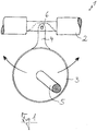
- FIG. 1 shows an inventive fishing rod 1 with a fishing rod 2 and a fishing reel 3.
- the Angel 1 is one for fly fishing.
- the fishing reel 3 further comprises a foot 4 for attachment of the fishing reel 3 to the fishing rod 2.
- the fishing reel 3 also has a handle 5 for operating the fishing reel 3.
- Both the foot 4 of the fishing reel 3 and the fishing rod 2 each have a recess for common reception of a releasable attachment means (here a fixing pin 6) for fixing the fishing reel 3 to the fishing rod 2.
- a fixing pin 6 which is for example a spring pin or push pin
- the fishing reel 3 After loosening or removing the fixing pin 6, the fishing reel 3 can be pivoted forward toward the tip of the fishing rod or rearward towards the end of the fishing rod and fixed in this position (see here in particular FIGS. 2a and 2b ).
- the fixing pin could also be a screw.
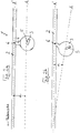
- FIGS. 2a and 2b The angel 1, the angular position ⁇ of the longitudinal axis A of the fishing reel and its winding reel to the longitudinal axis A 'of the fishing rod 2 can be changed, these two longitudinal axes A, A' in the same plane run.
- the fixing pin 6 serves to fix the desired angular position.
- FIG. 2a shows a position of the fishing reel 3, in which the longitudinal axis A of the fishing reel 3 runs parallel to the longitudinal axis A 'of the fishing rod.
- FIG. 2b shows the Angel 1 after the fishing reel 3 has been pivoted forward in the direction of the fishing tip and fixed in this position.
- FIG. 3 shows a further development of an inventive fishing rod 10 with a fishing rod 12 and a fishing reel 13, wherein the fishing reel 13 is shown in a disassembled position of the fishing rod for clarity.
- the fishing reel 13 has a foot 14 which serves to attach the fishing reel 13 to the fishing rod 12.
- the foot 14 is formed as a flat plate and has a hook-shaped element 15 at one end.
- the hook-shaped element 15 has on its underside a semicircular area 16.
- the hook-shaped element 15 protrudes from the main portion of the foot 14, namely the attachment area 17.
- In the attachment area 17 four superimposed recesses 18 are arranged, which are not completely separated from each other, but are introduced into each other in the mounting area 17.
- the fishing rod 2 is thickened.
- this thickened trained area 19 of the fishing rod 2 is in the fishing rod a arranged in the longitudinal direction of the fishing rod 2 rectangular recess 20 is introduced.
- the recess 20 serves to receive the foot 4.
- a 90 ° offset to the recess 20 arranged also rectangular recess 21 is introduced.
- This recess 21 protrudes on both sides beyond the recess 20 (ie, exactly speaking, two opposite recesses).
- a cylindrical pin 22 which is fixed in the recess 21.
- a further recess 23 in the thickened portion 19 of the fishing rod 2 is introduced.
- the recess 23 extends from an edge 24 of the thickened portion 19 initially to the recess 20 of the thickened portion 19.
- the recess 23 thus forms a continuous channel from the surface of the thickened portion 19 of the fishing rod 2 to the recess 20 in the interior of the thickened region 19.
- the recess 23 is continued on the opposite side of the recess 20, wherein the recess 23 is formed narrower at this point 23b and also does not lead to the surface of the thickened portion 19 (blind bore).
- Said narrower portion 23 b of the recess 23 is arranged in alignment with the wider portion 23 a of the recess 23.
- the longitudinal axes of the portions 23a and 23b of the recess 23 coincide.
- a spring pin 25 with a wider head portion 26 and a narrower neck portion 27.
- the wider portion 26 of the spring pin 25 is adapted to the dimension and contour of the wider portion 23 a of the recess 23.
- the narrower portion 27 of the spring pin 25 is adapted to the narrower portion 23 b of the recess 23.
- the spring pin 25 has an actuating ring 28, with which the spring pin 25 can be pulled so far out of the recess 23 that the narrower portion 27 of the spring pin 25, the recess 20 completely exposes.
- the spring pin 25 is first pulled so far out of the recess 20 that the foot can be guided with its fastening region 17 through the recess 20.
- the hook-shaped element 15 of the foot 14 is positioned such that the semi-circular portion 16 engages around the pin 22.
- the spring pin 25 must be pulled out of the recess 20.
- the pin 22 then serves as a pivot axis for the foot 4.
- the fishing reel 3 can then be pivoted to the desired position. Once this position is reached, the spring pin is released and snaps into one of the desired recesses 18 in the foot 14 a.
- the fishing rod 12 is partially surrounded by a cork jacket 29 for better gripping.
Landscapes
- Life Sciences & Earth Sciences (AREA)
- Environmental Sciences (AREA)
- Animal Husbandry (AREA)
- Biodiversity & Conservation Biology (AREA)
- Marine Sciences & Fisheries (AREA)
- Fishing Rods (AREA)
Claims (5)
- Canne à pêche comprenant une gaule (2, 12) et un moulinet de pêche (3, 13) ayant un pied (4, 14) qui sert à attacher le moulinet de pêche à la gaule, le pied (4, 14) du moulinet de pêche (3, 13) ainsi que la gaule (2, 12) ayant chacun au moins un évidement (18, 23) pour la réception jointe d'au moins un moyen d'attachement (6, 25) détachable destiné à fixer le moulinet de pêche à la gaule, caractérisée en ce que l'au moins un moyen d'attachement est une goupille à ressort et dans lequel une plaque d'attachement (17) du pied disposée dans la direction longitudinale de la gaule comprend plusieurs évidements et/ou perçages dentés et/ou perçages d'arbre disposés de manière superposée.
- Canne à pêche selon la revendication 1, caractérisée en ce que la position angulaire (a) de l'axe longitudinal (A) du moulinet de pêche (3, 13) et de la bobine d'enroulement de celui-ci est variable par rapport à la direction longitudinale (axe longitudinal A') de la gaule (2, 12), les deux axes longitudinaux (A, A') s'étendant dans le même plan, l'au moins un moyen d'attachement (6, 25) détachable servant à fixer la position angulaire désirée.
- Canne à pêche selon l'une quelconque des revendications précédentes, caractérisée en ce que le pied (4, 14) du moulinet de pêche (3, 13) est articulé de manière pivotable atour d'un axe (22) disposé sur la gaule (2, 12) et s'étendant perpendiculaire à la direction longitudinale du pied (ou de la gaule) et permettant au moulinet de pêche de pivoter vers la gaule et de s'en éloigner.
- Canne à pêche selon l'une quelconque des revendications précédentes, caractérisée en ce que la gaule comprend un autre évidement, préférablement un évidement continu (20), destiné à faire traverser des parties du pied (4, 14), notamment la plaque d'attachement (17) du pied, l'autre évidement étant décalé de préférence à 90° par rapport à l'évidement (23) destiné à recevoir le moyen d'attachement (6, 25) détachable.
- Canne à pêche selon l'une quelconque des revendications précédentes, caractérisée en ce que la gaule (2, 12) est renforcée, notamment plus épaisse, dans la zone (19) des évidements (20, 21, 23).
Applications Claiming Priority (3)
| Application Number | Priority Date | Filing Date | Title |
|---|---|---|---|
| DE102009037508 | 2009-08-17 | ||
| DE102010009139.1A DE102010009139B4 (de) | 2009-08-17 | 2010-02-23 | Angel |
| PCT/DE2010/000862 WO2011020452A1 (fr) | 2009-08-17 | 2010-07-23 | Canne à pêche |
Publications (2)
| Publication Number | Publication Date |
|---|---|
| EP2467014A1 EP2467014A1 (fr) | 2012-06-27 |
| EP2467014B1 true EP2467014B1 (fr) | 2017-09-06 |
Family
ID=43495555
Family Applications (1)
| Application Number | Title | Priority Date | Filing Date |
|---|---|---|---|
| EP10751778.1A Not-in-force EP2467014B1 (fr) | 2009-08-17 | 2010-07-23 | Canne et moulinet de pêche |
Country Status (5)
| Country | Link |
|---|---|
| US (1) | US20120180373A1 (fr) |
| EP (1) | EP2467014B1 (fr) |
| CA (1) | CA2770229C (fr) |
| DE (1) | DE102010009139B4 (fr) |
| WO (1) | WO2011020452A1 (fr) |
Citations (1)
| Publication number | Priority date | Publication date | Assignee | Title |
|---|---|---|---|---|
| DE19701236A1 (de) * | 1997-01-16 | 1998-07-23 | Kuntze Angelgeraete Dam | Angelrolle mit einem Fuß |
Family Cites Families (5)
| Publication number | Priority date | Publication date | Assignee | Title |
|---|---|---|---|---|
| FR958287A (fr) * | 1950-03-06 | |||
| US2191004A (en) * | 1938-08-05 | 1940-02-20 | Leonard Jean Gauthier | Fishing reel |
| SE319339B (fr) * | 1967-12-22 | 1970-01-12 | Abu Ab | |
| JPS5637875U (fr) * | 1979-08-31 | 1981-04-10 | ||
| US20060101703A1 (en) * | 2004-11-18 | 2006-05-18 | Han-Chi Lu | Reel seat for a fishing rod |
-
2010
- 2010-02-23 DE DE102010009139.1A patent/DE102010009139B4/de not_active Expired - Fee Related
- 2010-07-23 US US13/390,616 patent/US20120180373A1/en not_active Abandoned
- 2010-07-23 EP EP10751778.1A patent/EP2467014B1/fr not_active Not-in-force
- 2010-07-23 WO PCT/DE2010/000862 patent/WO2011020452A1/fr not_active Ceased
- 2010-07-23 CA CA2770229A patent/CA2770229C/fr active Active
Patent Citations (1)
| Publication number | Priority date | Publication date | Assignee | Title |
|---|---|---|---|---|
| DE19701236A1 (de) * | 1997-01-16 | 1998-07-23 | Kuntze Angelgeraete Dam | Angelrolle mit einem Fuß |
Also Published As
| Publication number | Publication date |
|---|---|
| CA2770229A1 (fr) | 2011-02-24 |
| DE102010009139A1 (de) | 2011-02-24 |
| CA2770229C (fr) | 2014-04-22 |
| WO2011020452A1 (fr) | 2011-02-24 |
| EP2467014A1 (fr) | 2012-06-27 |
| US20120180373A1 (en) | 2012-07-19 |
| DE102010009139B4 (de) | 2015-12-31 |
Similar Documents
| Publication | Publication Date | Title |
|---|---|---|
| EP0575929B1 (fr) | Bouton d'une ou à une manivelle pour moulinet de pêche | |
| DE3604700C2 (fr) | ||
| EP0455251B1 (fr) | Attelage de remorque démontable | |
| EP0101040B1 (fr) | Fixation d'un pied de mât pour planche à voile | |
| EP2467014B1 (fr) | Canne et moulinet de pêche | |
| DE69800505T2 (de) | Vorrichtung zum lösbaren Halten einer Angelleine | |
| DE60010901T2 (de) | Segmentierte rolle | |
| DE2923620B2 (de) | Verbindungseinrichtung zwischen der Zugstange eines Ackerschleppers und dem deichseiförmigen Zugglied eines nachgeschleppten, über Zapfwelle antreibbaren Gerätes | |
| EP1939519B1 (fr) | Trépied | |
| WO1995000013A1 (fr) | Epuisette, notamment pour la peche | |
| DE60119011T2 (de) | Führung eines Steuerelements für ein Fahrrad | |
| EP3262918B1 (fr) | Releveur d'épis | |
| DE102019134832A1 (de) | Knick-Drehmomentschlüssel | |
| DE6941979U (de) | Rollenpolierwerkzeug. | |
| DE3040766A1 (de) | Skibremse | |
| DE19701236C2 (de) | Angelrolle mit einem Fuß | |
| DE10303990A1 (de) | Halmteiler | |
| DE3235138A1 (de) | Fahrradgangschaltung | |
| DE69003628T2 (de) | Zerlegbarer, aus zwei Sektionen bestehenden Ski. | |
| DE102021116680B4 (de) | Gartenschere mit kraftsparendem aufbau | |
| DE10297388T5 (de) | Handgriff mit Leistungsreguliervorrichtung | |
| EP0886467B1 (fr) | Dispositif pour declencher une butee de canne a peche | |
| EP2014547B1 (fr) | Beaupré pivotable | |
| DE60112693T2 (de) | Gelenk für eine Kugel-Rampen-Betätigungseinrichtung | |
| EP3440921B1 (fr) | Unité d'entraînement pour un convoyeur rotatif, doigt d'entraînement et convoyeur rotatif |
Legal Events
| Date | Code | Title | Description |
|---|---|---|---|
| PUAI | Public reference made under article 153(3) epc to a published international application that has entered the european phase |
Free format text: ORIGINAL CODE: 0009012 |
|
| 17P | Request for examination filed |
Effective date: 20120206 |
|
| AK | Designated contracting states |
Kind code of ref document: A1 Designated state(s): AL AT BE BG CH CY CZ DE DK EE ES FI FR GB GR HR HU IE IS IT LI LT LU LV MC MK MT NL NO PL PT RO SE SI SK SM TR |
|
| DAX | Request for extension of the european patent (deleted) | ||
| 17Q | First examination report despatched |
Effective date: 20160812 |
|
| GRAP | Despatch of communication of intention to grant a patent |
Free format text: ORIGINAL CODE: EPIDOSNIGR1 |
|
| STAA | Information on the status of an ep patent application or granted ep patent |
Free format text: STATUS: GRANT OF PATENT IS INTENDED |
|
| INTG | Intention to grant announced |
Effective date: 20170502 |
|
| GRAS | Grant fee paid |
Free format text: ORIGINAL CODE: EPIDOSNIGR3 |
|
| GRAA | (expected) grant |
Free format text: ORIGINAL CODE: 0009210 |
|
| STAA | Information on the status of an ep patent application or granted ep patent |
Free format text: STATUS: THE PATENT HAS BEEN GRANTED |
|
| AK | Designated contracting states |
Kind code of ref document: B1 Designated state(s): AL AT BE BG CH CY CZ DE DK EE ES FI FR GB GR HR HU IE IS IT LI LT LU LV MC MK MT NL NO PL PT RO SE SI SK SM TR |
|
| REG | Reference to a national code |
Ref country code: GB Ref legal event code: FG4D Free format text: NOT ENGLISH |
|
| REG | Reference to a national code |
Ref country code: CH Ref legal event code: EP Ref country code: AT Ref legal event code: REF Ref document number: 924861 Country of ref document: AT Kind code of ref document: T Effective date: 20170915 |
|
| REG | Reference to a national code |
Ref country code: IE Ref legal event code: FG4D Free format text: LANGUAGE OF EP DOCUMENT: GERMAN |
|
| REG | Reference to a national code |
Ref country code: DE Ref legal event code: R096 Ref document number: 502010014132 Country of ref document: DE |
|
| REG | Reference to a national code |
Ref country code: NL Ref legal event code: MP Effective date: 20170906 |
|
| REG | Reference to a national code |
Ref country code: LT Ref legal event code: MG4D |
|
| PG25 | Lapsed in a contracting state [announced via postgrant information from national office to epo] |
Ref country code: NO Free format text: LAPSE BECAUSE OF FAILURE TO SUBMIT A TRANSLATION OF THE DESCRIPTION OR TO PAY THE FEE WITHIN THE PRESCRIBED TIME-LIMIT Effective date: 20171206 Ref country code: FI Free format text: LAPSE BECAUSE OF FAILURE TO SUBMIT A TRANSLATION OF THE DESCRIPTION OR TO PAY THE FEE WITHIN THE PRESCRIBED TIME-LIMIT Effective date: 20170906 Ref country code: LT Free format text: LAPSE BECAUSE OF FAILURE TO SUBMIT A TRANSLATION OF THE DESCRIPTION OR TO PAY THE FEE WITHIN THE PRESCRIBED TIME-LIMIT Effective date: 20170906 Ref country code: HR Free format text: LAPSE BECAUSE OF FAILURE TO SUBMIT A TRANSLATION OF THE DESCRIPTION OR TO PAY THE FEE WITHIN THE PRESCRIBED TIME-LIMIT Effective date: 20170906 Ref country code: SE Free format text: LAPSE BECAUSE OF FAILURE TO SUBMIT A TRANSLATION OF THE DESCRIPTION OR TO PAY THE FEE WITHIN THE PRESCRIBED TIME-LIMIT Effective date: 20170906 |
|
| PG25 | Lapsed in a contracting state [announced via postgrant information from national office to epo] |
Ref country code: GR Free format text: LAPSE BECAUSE OF FAILURE TO SUBMIT A TRANSLATION OF THE DESCRIPTION OR TO PAY THE FEE WITHIN THE PRESCRIBED TIME-LIMIT Effective date: 20171207 Ref country code: ES Free format text: LAPSE BECAUSE OF FAILURE TO SUBMIT A TRANSLATION OF THE DESCRIPTION OR TO PAY THE FEE WITHIN THE PRESCRIBED TIME-LIMIT Effective date: 20170906 Ref country code: LV Free format text: LAPSE BECAUSE OF FAILURE TO SUBMIT A TRANSLATION OF THE DESCRIPTION OR TO PAY THE FEE WITHIN THE PRESCRIBED TIME-LIMIT Effective date: 20170906 Ref country code: BG Free format text: LAPSE BECAUSE OF FAILURE TO SUBMIT A TRANSLATION OF THE DESCRIPTION OR TO PAY THE FEE WITHIN THE PRESCRIBED TIME-LIMIT Effective date: 20171206 |
|
| PG25 | Lapsed in a contracting state [announced via postgrant information from national office to epo] |
Ref country code: NL Free format text: LAPSE BECAUSE OF FAILURE TO SUBMIT A TRANSLATION OF THE DESCRIPTION OR TO PAY THE FEE WITHIN THE PRESCRIBED TIME-LIMIT Effective date: 20170906 |
|
| PG25 | Lapsed in a contracting state [announced via postgrant information from national office to epo] |
Ref country code: CZ Free format text: LAPSE BECAUSE OF FAILURE TO SUBMIT A TRANSLATION OF THE DESCRIPTION OR TO PAY THE FEE WITHIN THE PRESCRIBED TIME-LIMIT Effective date: 20170906 Ref country code: PL Free format text: LAPSE BECAUSE OF FAILURE TO SUBMIT A TRANSLATION OF THE DESCRIPTION OR TO PAY THE FEE WITHIN THE PRESCRIBED TIME-LIMIT Effective date: 20170906 Ref country code: RO Free format text: LAPSE BECAUSE OF FAILURE TO SUBMIT A TRANSLATION OF THE DESCRIPTION OR TO PAY THE FEE WITHIN THE PRESCRIBED TIME-LIMIT Effective date: 20170906 |
|
| PG25 | Lapsed in a contracting state [announced via postgrant information from national office to epo] |
Ref country code: SM Free format text: LAPSE BECAUSE OF FAILURE TO SUBMIT A TRANSLATION OF THE DESCRIPTION OR TO PAY THE FEE WITHIN THE PRESCRIBED TIME-LIMIT Effective date: 20170906 Ref country code: IT Free format text: LAPSE BECAUSE OF FAILURE TO SUBMIT A TRANSLATION OF THE DESCRIPTION OR TO PAY THE FEE WITHIN THE PRESCRIBED TIME-LIMIT Effective date: 20170906 Ref country code: SK Free format text: LAPSE BECAUSE OF FAILURE TO SUBMIT A TRANSLATION OF THE DESCRIPTION OR TO PAY THE FEE WITHIN THE PRESCRIBED TIME-LIMIT Effective date: 20170906 Ref country code: IS Free format text: LAPSE BECAUSE OF FAILURE TO SUBMIT A TRANSLATION OF THE DESCRIPTION OR TO PAY THE FEE WITHIN THE PRESCRIBED TIME-LIMIT Effective date: 20180106 Ref country code: EE Free format text: LAPSE BECAUSE OF FAILURE TO SUBMIT A TRANSLATION OF THE DESCRIPTION OR TO PAY THE FEE WITHIN THE PRESCRIBED TIME-LIMIT Effective date: 20170906 |
|
| REG | Reference to a national code |
Ref country code: DE Ref legal event code: R097 Ref document number: 502010014132 Country of ref document: DE |
|
| PLBE | No opposition filed within time limit |
Free format text: ORIGINAL CODE: 0009261 |
|
| STAA | Information on the status of an ep patent application or granted ep patent |
Free format text: STATUS: NO OPPOSITION FILED WITHIN TIME LIMIT |
|
| PG25 | Lapsed in a contracting state [announced via postgrant information from national office to epo] |
Ref country code: DK Free format text: LAPSE BECAUSE OF FAILURE TO SUBMIT A TRANSLATION OF THE DESCRIPTION OR TO PAY THE FEE WITHIN THE PRESCRIBED TIME-LIMIT Effective date: 20170906 |
|
| 26N | No opposition filed |
Effective date: 20180607 |
|
| PG25 | Lapsed in a contracting state [announced via postgrant information from national office to epo] |
Ref country code: SI Free format text: LAPSE BECAUSE OF FAILURE TO SUBMIT A TRANSLATION OF THE DESCRIPTION OR TO PAY THE FEE WITHIN THE PRESCRIBED TIME-LIMIT Effective date: 20170906 |
|
| PG25 | Lapsed in a contracting state [announced via postgrant information from national office to epo] |
Ref country code: MT Free format text: LAPSE BECAUSE OF FAILURE TO SUBMIT A TRANSLATION OF THE DESCRIPTION OR TO PAY THE FEE WITHIN THE PRESCRIBED TIME-LIMIT Effective date: 20170906 |
|
| REG | Reference to a national code |
Ref country code: CH Ref legal event code: PL |
|
| GBPC | Gb: european patent ceased through non-payment of renewal fee |
Effective date: 20180723 |
|
| PG25 | Lapsed in a contracting state [announced via postgrant information from national office to epo] |
Ref country code: MC Free format text: LAPSE BECAUSE OF FAILURE TO SUBMIT A TRANSLATION OF THE DESCRIPTION OR TO PAY THE FEE WITHIN THE PRESCRIBED TIME-LIMIT Effective date: 20170906 Ref country code: LU Free format text: LAPSE BECAUSE OF NON-PAYMENT OF DUE FEES Effective date: 20180723 |
|
| REG | Reference to a national code |
Ref country code: BE Ref legal event code: MM Effective date: 20180731 |
|
| REG | Reference to a national code |
Ref country code: IE Ref legal event code: MM4A |
|
| PG25 | Lapsed in a contracting state [announced via postgrant information from national office to epo] |
Ref country code: IE Free format text: LAPSE BECAUSE OF NON-PAYMENT OF DUE FEES Effective date: 20180723 Ref country code: GB Free format text: LAPSE BECAUSE OF NON-PAYMENT OF DUE FEES Effective date: 20180723 Ref country code: LI Free format text: LAPSE BECAUSE OF NON-PAYMENT OF DUE FEES Effective date: 20180731 Ref country code: CH Free format text: LAPSE BECAUSE OF NON-PAYMENT OF DUE FEES Effective date: 20180731 Ref country code: FR Free format text: LAPSE BECAUSE OF NON-PAYMENT OF DUE FEES Effective date: 20180731 |
|
| PG25 | Lapsed in a contracting state [announced via postgrant information from national office to epo] |
Ref country code: BE Free format text: LAPSE BECAUSE OF NON-PAYMENT OF DUE FEES Effective date: 20180731 |
|
| REG | Reference to a national code |
Ref country code: AT Ref legal event code: MM01 Ref document number: 924861 Country of ref document: AT Kind code of ref document: T Effective date: 20180723 |
|
| PG25 | Lapsed in a contracting state [announced via postgrant information from national office to epo] |
Ref country code: AT Free format text: LAPSE BECAUSE OF NON-PAYMENT OF DUE FEES Effective date: 20180723 |
|
| PG25 | Lapsed in a contracting state [announced via postgrant information from national office to epo] |
Ref country code: TR Free format text: LAPSE BECAUSE OF FAILURE TO SUBMIT A TRANSLATION OF THE DESCRIPTION OR TO PAY THE FEE WITHIN THE PRESCRIBED TIME-LIMIT Effective date: 20170906 |
|
| PG25 | Lapsed in a contracting state [announced via postgrant information from national office to epo] |
Ref country code: HU Free format text: LAPSE BECAUSE OF FAILURE TO SUBMIT A TRANSLATION OF THE DESCRIPTION OR TO PAY THE FEE WITHIN THE PRESCRIBED TIME-LIMIT; INVALID AB INITIO Effective date: 20100723 Ref country code: PT Free format text: LAPSE BECAUSE OF FAILURE TO SUBMIT A TRANSLATION OF THE DESCRIPTION OR TO PAY THE FEE WITHIN THE PRESCRIBED TIME-LIMIT Effective date: 20170906 |
|
| PG25 | Lapsed in a contracting state [announced via postgrant information from national office to epo] |
Ref country code: MK Free format text: LAPSE BECAUSE OF NON-PAYMENT OF DUE FEES Effective date: 20170906 Ref country code: CY Free format text: LAPSE BECAUSE OF FAILURE TO SUBMIT A TRANSLATION OF THE DESCRIPTION OR TO PAY THE FEE WITHIN THE PRESCRIBED TIME-LIMIT Effective date: 20170906 |
|
| PG25 | Lapsed in a contracting state [announced via postgrant information from national office to epo] |
Ref country code: AL Free format text: LAPSE BECAUSE OF FAILURE TO SUBMIT A TRANSLATION OF THE DESCRIPTION OR TO PAY THE FEE WITHIN THE PRESCRIBED TIME-LIMIT Effective date: 20170906 |
|
| PGFP | Annual fee paid to national office [announced via postgrant information from national office to epo] |
Ref country code: DE Payment date: 20230920 Year of fee payment: 14 |
|
| REG | Reference to a national code |
Ref country code: DE Ref legal event code: R119 Ref document number: 502010014132 Country of ref document: DE |
|
| PG25 | Lapsed in a contracting state [announced via postgrant information from national office to epo] |
Ref country code: DE Free format text: LAPSE BECAUSE OF NON-PAYMENT OF DUE FEES Effective date: 20250201 |